Jump to content

Dr PR

NRG Member
  • Posts

    1,471
  • Joined

  • Last visited

Everything posted by Dr PR

  1. Beautiful work! Just thinking about that rigging makes me shudder - I hate tying knots in CAD! You are a glutton for punishment. Phil
  2. Valeriy, The level of detail Vladimir has put into his 1:200 model is exceptional! I can see he is still working on a few details here and there. One thing I did notice is that all of the whip antennas on the fore tower are long. In fact only the two at the top that project in a "V" from the top platform were the NT-66047 35 foot whip antennas. I think the rest were 10 foot AT-252/SR antennas. Note: The "Antenna Group" for the 10 foot antennas was AN/SRA-17, and that is what is listed on some lists of ship's antennas. But the antenna was the AT-252/SR. It was mounted on top of a box containing an antenna tuner. Together they make up the SRA-17. Also, the actual length of the antenna and insulator base was 10.5 feet. Phil
  3. Valeriy, Tell Vladimir his work is beautiful! Of course, I am not biased ... I examine models of the Okie Boat with a very critical eye, and his details are spot on! I am glad he has painted the tops of the smoke pipes and towers black like they were on the real ship. I made them gray so the details would be visible in the CAD images, but eventually I need to make them black. Several other fellows have said they were working on a model of the ship, but these are the first photos I have seen of a model built according to my drawings. Thank you very much for posting them! I hope my 1:96 model looks as good. How long has he been working on this model? If you or he (or any one else) have questions please contact me by email through my web page https://www.okieboat.com/Contact page.html Phil
  4. Fellows, Thanks for the comments. Actually, I'm glad you didn't say I am crazy for taking on such a lengthy project! Phil
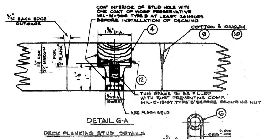
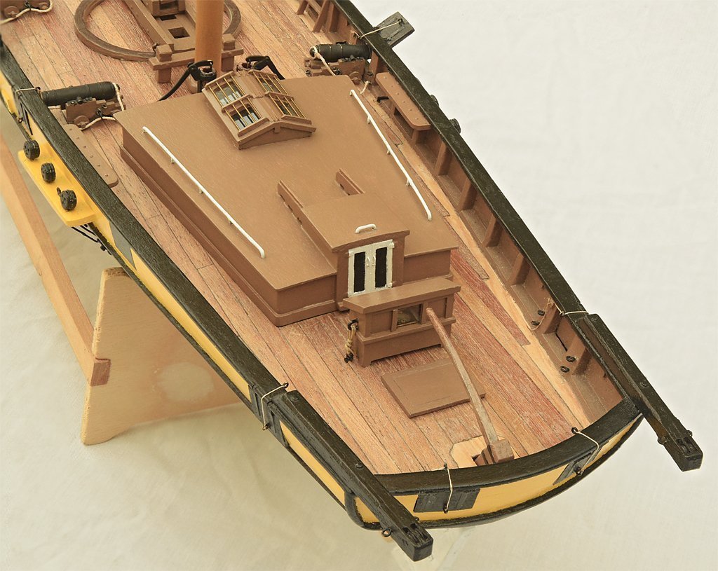
  5. THE MAIN DECK I consider the main deck to be part of the hull, but it was constructed separately in the CAD model. Most of the equipment and fittings on the fo'c'sle were original 1940s Cleveland class parts. The two 20mm gun tubs had been removed and a large discone antenna took their place. Originally the OK City had the antenna mounted on a short open lattice tower, just like the configuration of the USS Little Rock CG-4 museum ship in Buffalo. But the tower was enclosed later in a cylindrical compartment that was used to stow anchor handling gear. The sailors called this cylindrical structure the "beer can." The original 1960 CLG discone antenna was replaced a few years later with a larger version with more elements. The two "wildcats" were large sprockets that fed the anchor chain into and out of the chain pipes to the chain lockers below. These and the brake controls, plus the capstans and their controls, were original equipment. The blueprints showed all of the anchor equipment, above and below deck, in great detail, and even told how to operate it. Some ships painted the chain pipes red on the port side and green on the starboard, but they were deck gray on the Okieboat. The Captain said he didn't want his ship to look like a circus boat! The blueprints gave only a rough outline of the changes to the wooden decks for the CLG conversion. I had to depend upon a dozen or so high resolution photos to see how it was done. But the original CL blueprints told how the planks were fitted together, and the CLG photos showed that the new deck was assembled in the same way. The deck planks were 2"x4" and 18 feet long originally. Most were cut to 16 foot or shorter lengths when they were installed. Plank ends aligned with the ship's frames at 4 foot intervals. The planks were a laminate of 1" of teak on top over 1" of Douglas fir on bottom. They were bolted down to threaded studs welded to the deck plates, with the nuts fitting into recessed cavities that were filled with white lead and then sealed with a teak plug. I didn't try to model the plugs! On the original Clevelands the wood deck extended forward to just in front of the #1 turret. Perhaps this was to minimize flash burns from the firing of the 6" guns. On CLG-5 the wood deck was extended forward to just behind the wildcats and capstans. Some of the other CLGs also had some sort of wood deck extension, but not all were like the OK City's. On the CLGs the wood deck extended aft only to about midway down the side of the missile house. The Talos missile boosters produced a 60-70 foot flame that could flash up the side of the missile house if the shot was fired almost directly aft. This would have burned the wood deck. As it was we had to repaint a large portion of the metal deck after each shot. Margin boards 9" wide were fitted around the deck edges, around the superstructure, and around hatches, vents and other deck fittings. The margin boards were 2 1/2" thick along edges next to deck house and hatch sides, and were trimmed to 2" where the deck planks joined - this caused water to flow away from the house sides. If the deck planks joined the margin boards with an angle between 45 degrees and 90 degrees the planks were trimmed to fit the margin boards. But if the join angle on the plank was less than 45 degrees the deck planks were notched into the margin boards so the planks didn't have sharp pointed ends that might break off easily. The nibs were cut perpendicular to the length of the planks, and were half the plank width. The minimum width of the margin board at the notches could not be less than 6". There were lots of planks and joins. It took a month or two to create the wooden deck. I'm not sure I look forward to repeating this on the real 1:96 model! The stanchions along the edge of the main deck were articulated affairs that could be folded down to lower the life lines during underway replenishment. In practice during UNREPS the stanchions and lifelines were just removed to get them out of the way. The ship had a 15" wide waterway between the wood deck and the hull side. The stanchion base was welded to the top of the hull plating and to a 3/8" flat bar that bordered the wood deck. But the height of the hull plating above the main deck and the angle of the hull plating varied along the length of the ship. Consequently, no two stanchion bases were the same and I had to fit each one separately. At the bow and stern, where there was no wooden deck, some stanchion pipes fitted into cylindrical pipe sleeves welded to the deck. There were 20 different stanchion configurations. The stanchions were mostly the same type on opposite sides of the ship, but there were a few differences. The bitts and chocks on the CLG were mostly in the same positions as for the original CL hull, but there was one interesting difference on the Okie Boat. The bitts were standard 14" bitts that were used on cruisers. But the USS Oklahoma City CLG-5 had two 10" bitts on the fo'c'sle outboard of the capstans. The wood deck was trimmed around them. The OK City was the only Cleveland class ship, CL or CLG, that had these smaller bitts. Almost everything on the fantail was new after the CLG modification. The airplane hanger, aircraft crane and catapults were removed, as were the two aft 6"/47 turrets and 40mm gun tubs at the stern. These were replaced by the Talos missile launcher, a helo deck and several ventilators at the stern. The helo deck had fold down life nets at the deck edges - these were very tedious to model! The tall whip antennas also folded down for flight operations. They were originally on top of the large "D" shaped ventilators, but were later lowered and moved outboard. The flagstaff on the stern was one of the most difficult parts to model. It was raised in port - except when we were conducting flight operations - and folded down and clamped in a fixture on one of the chocks when we were at sea. The ship had at least four different flagstaffs! The CL and CLG blueprints showed two configurations and early CLG photos showed a third. But I could see from photos that the flagstaff of 1971 was different, but the photos were too grainy to tell just how it was constructed. One day I was looking through the cruise book and noticed a photo of a sailor standing stern lookout right beside the life ring that was attached to the electrical cabinet. The flagstaff was lowered and I could see details of the fixture on the chock and how the staff was fastened down. Then someone sent me a nice high resolution photo of a ship docked at a pier in the distance, with the stern of the OK City at the edge of the photo. There I could see the base of the flagstaff! That allowed me to finish the model of the flagstaff, and I think this configuration was still there at decommissioning in 1979. The staff itself was easy to model - the original USS Oklahoma City CG-5 flagstaff is outside the American Legion Center at Newport, Oregon, about a hour from my home. There were a number of winches and smaller fittings on the main deck but I will discuss them in a post about the ship's boats and boat handling gear. The last large feature of the main deck was the triple 6"/47 turret. The Clevelands had four of these turrets. Only the forward turret #1 remained after the CLG flagship conversions. The blueprints showed the construction of the turret gun house, barbette, and projectile and powder handling gear. But I have never found drawings of the 6" Mark 16 47 caliber guns. The early Clevelands had range finders on the #1 turret, but these were removed on later ships to reduce topside weight. The OK City never had the rangefinders on this turret. The Cleveland's #1 and #4 turrets had access doors on the rear. The superelevated turrets #2 and #3 had access doors on the bottom rear. A tripod was stowed on the turret top. It could be assembled for highline transfers on either side of the ship. We normally took on ammunition on the starboard side. The highline cable passed over the top of the tripod and fastened to the main deck on the side opposite the transfer ship. Phil
  6. THE HULL, PART 5 The hull had a lot of details. Here are a few pictures. I had blueprints for the rudder, propellers, prop shafts and struts, propeller guards and boat booms, so they were pretty easy to model. Well, the propellers tested my ability to model complex curved shapes. My goal is to use the 3D file to drive a NC milling machine to make the 1:96 scale props. There are four different propellers, two right hand rotation and two left hand. In addition, the blades of the outboard props are slightly wider than the inboard props because they were positioned higher (not as deep in the water) where water density and pressure were a bit less, so the wider blades gave them the same thrust at the same RPM as the inboard props. The blueprints revealed something you don't see in photos - the propeller shafts entered the hull in recessed shaft alleys that had "portable" (removable) covers. The propeller struts were very interesting. The struts and hubs were single cast steel pieces. The after struts were about 12 feet long and the hubs were about 7 feet long and 2 1/2 feet diameter. After the struts and hubs were attached to the hull they were machined in place to be aligned with the propeller shafts! That would have been something to see. The inner diameter was about 2 feet and was machined to accommodate six cylindrical bearings that the shaft turned in. Along the side of the hull were many split pipe drain covers, with curved steel pipe bumpers to protect them. These covered overboard discharges from showers, toilets, etc. They were absent on the original 1944 hull, and were added during the CLG conversion. They caused quite a bit of consternation because no two photos of the ship show the same configuration! There were from 14 to 24 on the starboard side, and more on the port side. Some photos clearly show weld marks on the hull where a pipe and bumpers had been. Apparently they were occasionally ripped off, perhaps by heavy seas or contact with piers. In any case, I had to make a best guess about how many were on the ship in the July 1971 period I was modelling. The ship carried two accommodation ladders, one fore (officers) and the other aft (crew). They could be installed on either side of the ship. During the ship's career the ladders were changed at least twice. The blueprints showed the original CL ladders and the CLG ladders, but photos showed the 1971 ladders to be different from both. I had to piece together what they looked like from a combination of blueprints and photos. I don't intend to show them rigged, but I had to construct them in order to get all the pieces to fit together correctly. Then I placed the disassembled parts in the stowed positions on the superstructure. The hawse pipe and doughnut-shaped bolster were a challenge. The 2D blueprints tried to show the contours of the bolster but I had to scratch my head a while to figure out the 3D shape. Fortunately I had photos to work from, but it was still a challenge. I drew this in 2007 and learned a lot about drawing free form shapes! The surface is a single grid that wraps around into the hawse pipe. The anchor was another tricky job, with lots of intersecting curves that were interesting to model. The anchor stock was drawn up into the hawse pipe when stowed. When the anchor was let go the anchor chain payed out through the hawse pipe. The ship actually had two slightly different US Navy 13,000 pound anchors. One of the original anchors was lost on the 1945 shakedown cruise and had to be replaced. The first two Cleveland class ships, USS Cleveland CL-55 and USS Columbia CL-56, had the stern lights attached to the outside of the hull plating. The white stern light and blue formation lights were used for formation steaming, and the conical light was the wake light that illuminated the ship's wake. All subsequent ships of the class carried these lights in a recess in the hull plating that provided better protection from following seas. You would think that these lights would have been positioned along the ship's center line, and it looked this way in some photos. But others seemed to show the opening off center to starboard. The hull plating blueprints showed the opening but gave no dimensions and the position was still ambiguous. But the drawing referenced the blueprint for the stern lights so I searched for it on the microfilm. No luck! That particular drawing was not in the blueprint set! Arrggh! I eventually got the idea of looking at the blueprints for the hull framing, and sure enough the recess was offset to starboard. The reason was pretty obvious when I looked at the drawings - the original ships had a large airplane crane on the centerline at the stern, and the hull frame below it was a massive "I" beam. The recess fit up against that centerline frame. The drawings also gave the dimensions. Of course, after I did all that searching someone sent me a very nice photo of the stern that clearly showed where the opening was. Phil
  7. THE HULL, PART 4 I decided to start over on the hull to build it up plate by plate like the real hull. I have the blueprints that show the general arrangement and plate thickness. My plan was to use the original smooth hull and project the plate outlines onto it. Then I created individual grids for each plate, and built up the thickness to what was shown in the drawings. This turned out to be very tricky! Cleveland class hull plating was not the simple upper strake overlapping the strake below it that you see in many ships. Nor did it have alternating strakes with every other one on top of it's neighbors. One strake did overlap the strakes above and below. Some were overlapped by higher strakes and then overlapped the strake below it. Some were overlapped above and below. A few were just butted together edge to edge. And the plates were not all rectangular - some had more than four sides! To make matters more complicated the blueprints did not give dimensions for any of the plates, and one important blueprint was missing! I was pretty frustrated and thought about giving up on the hull plating. But then I fortuitously stumbled across the mold loft offsets in the microfilm set. There I found the Tables of Sight Edges, and that was the key. These were the familiar tables with hundreds of F-I-E numbers like the Table of Offsets. But these numbers told where the edges of every plate were to be positioned on the hull. Eureka! While the ship was under construction the builders used surveying techniques to position the plates according to the elevations in the sight edges tables. I used the data to create the sight lines, as shown in the picture. Then I projected these lines onto the smooth hull. The blueprints showed where the fore-aft edges of the plates were located at specific frames. That was all I needed to know to create the template lines for the plating. Below is a drawing of the hull plating configuration. Individual strakes are in light and dark shades of the same color. The two sides were mirror images except for the garboard strake (red) outboard of the keel and half siding. The garboard strake plates were different port and starboard to prevent alignment of seams on opposite sides of the keel. There were about 480 plates in 15 strakes. Notice the bow - here the strakes were vertical up to the upper strake. I had never seen this before, but it makes sense. I guess the bow was assembled in the yards and then moved into position in the ways. At the thinnest part of the bow (at the full load water line) one of the starboard side plates was added in two pieces. This allowed a workman to reach inside and finish the internal welding. Then the additional plate was added to finish the job. OK, so I knew where the plates were located, what their shapes were, and where the internal surfaces were on the hull. To finish the plating I had to build up each one to the proper thickness. Plate thickness varied a great deal, being thickest near midships and down low where water pressure was greatest. Steel plate is measured by weight, in pounds per square foot - for example 1" thick plating weighed 40.8 pounds per square foot, and was marked 40#. At the bow the sheer strake (main deck level) was 10# (1/4 inch) and the plating for the bulbous bow was 30# (3/4 inch) just above the keel. Midships the sheer strake was 35# (7/8 inch) and at the keel it was 28# (11/16 inch). The keel midships was 68# (1 5/8 inch) and 35# (7/8 inch) at the bow. Since the internal surfaces aligned plate to plate, where the thickness varied there was a step in the hull exterior surface. The blueprints instructed that after welding was complete, where plates of different thicknesses came together below the full load water line the high edges were to be ground back at a 45 degree angle to reduce drag. This was getting complicated! To add to the fun I wanted to model all of the hull openings (seachests). The microfilm contained lists of seachests telling the frames where they were located, but not giving the elevations. But the drawings showed where the openings were on each hull plate. And finally, there were blueprints for each seachest showing the dimensions and how they were attached to the hull. There were 32 seachests in the engineering spaces and a half dozen more scattered about the hull. Six months later I had the fully plated hull, complete with external backing plates above the water line, hull openings, rudder, propellers and shafts, stern light opening, armor belts, bolsters for the anchors, the eyes, boat booms, propeller guards, split pipe drain covers, and the odd doughnut shaped bolster on the stem for the WWII era minesweep paravane cables. Each of these features was a drawing in itself, based upon blueprints and photos. Phil
  8. THE HULL, PART 3 The Cleveland class hull was far more complex than the 40 foot boat hull. It had a skeg like the smaller boat, but it also had a fairwater on the aft end of the skeg to reduce turbulence as water flowed past the skeg. It had knuckles, or sharp breaks to the smooth curves, at the third deck level just above the armor belts (they were attached to the outside of the hull plating). It also had a bulbous bow and a very complex transom that was semicircular at the main deck level and almost square below the full load water line. I used many different surface grids to cover the entire hull. Only the starboard half is shown - the port side was a mirror image of the starboard side. The hull was built up in three main groups, the upper hull, boot topping (water line), and lower hull. The upper hull is three grids light blue and green. The boot topping is three grids dark green and dark blue. The lower hull was the most complex shape and is made up of three grids, orange, yellow and red, plus several more for the keel and skeg fairwater . The yellow grid has a sharp knuckle near the top at the third deck level. The bow has some complex curvature to create the bulbous bow. The wireframe view of the grids is shown below. Notice the different grid densities (grid line spacing). For long and fairly smooth surfaces you do not need a lot of facets. But where surfaces are highly curved the grid must have many smaller facets. So why not just make all the grids with dense facets? This causes the file size to grow very large, and large files are much slower to work with. After a few more modifications and details like the propellers and shafts, the rudder and bilge keel I finished the first pass at creating the ship's hull. It was OK ... But while I was working on this I was also following some other CAD model builds on line. One model in particular, a destroyer escort by a fellow in Perm, Russia, really impressed me. He was adding small details that I had not planned to model, such as nuts and bolts, wiring and external piping. I sent him drawings of the quick acting watertight door and he returned a working CAD model! When the handle turned the dogs rotated and the door opened!! A model of a battleship included threads on the turnbuckles in the rigging. Another fellow modeled the entire internal frame and deck structure of the INS Yamato! WOW! This was setting the mark pretty high. I decided that if they could include such fine detail, so could I. That was a consequential decision! A 610 foot cruiser probably has five times as much external detailing as a 300 foot destroyer escort - I hadn't taken that into account. So my focus changed to including every visible detail on the ship's exterior, down to nuts, bolts, screws and rivets as small as 3/16 inch diameter. However, I did decide to leave out the threads on the bolts and screws - that would have made the file sizes ten times larger. After some preliminary work I decided to not model the internal frames of the ship. This called for a lot more detailed research, close scrutiny of a lot of photos, and accumulation of drawings and data sheets for small parts like antennas, binoculars, searchlights, etc. Creation of the model slowed to a snails pace. Phil
  9. THE HULL, PART 2 The steps to create a complex surface are different in each CAD program, so I will use the methods and terminology of the DesignCAD program. But the process is similar in all programs. The idea is to select a collection of curves to serve as templates for the surface to be stretched over. In this case I selected station lines and used a function to create a fishnet grid over the lines. The program interpolates the spacing between individual station lines and fills in the grid between them to make the surface. Here is an example. The template curves are shown in dark red. After they are selected and the surface generation function is executed you get the blue fishnet surface grid. It looks like a fishnet in the wireframe view shown here, but it renders as a smooth surface. Of course, it really isn't that easy! The Okie Boat's hull was very complex, so I will start with a simpler example, the hull of a 40 foot utility or personnel boat, The forward (green) station lines form a smooth hull surface top to keel from the bow back to the skeg. Here the port and starboard sides of the boat are mirror images so it is only necessary to create the surface for one side and then mirror it to make the other side. The after station lines (red) also form a smooth surface across the width of the hull. But at the skeg - the aft end of the keel - there is a sudden sharp discontinuity in the hull surface. The end surface of the skeg is flat, and the forward and aft hull surfaces do not wrap around to it. If I tried to create the entire hull from one surface it would be badly twisted and wrinkled at this discontinuity. The same is also true at the sharp knuckle between the after hull surface and the transom. The solution is to create the hull from six different grid surfaces, as shown in the image. It can be tricky to get the forward and after surfaces to align and fit together with no wrinkles or leaks, but as you can see it can be done. Patience is a virtue. Phil
  10. THE HULL, PART 1 I'll start the CAD model description with the ship's hull. I use the program DesignCAD 3D MAX, an inexpensive but very capable CAD program. I have been using it in my work and for hobbies since 1988. First I need to introduce some terminology. The Base Line is an imaginary line running the length of the hull on the center line - everything is referenced to the Base Line, especially vertical positions. The Base Line is often along the ship's keel, but sometimes with small boats it is drawn above the boat (actually, the boats are built upside down, so the base line is somewhere below the inverted boat). With the Cleveland class hull the Base Line was on top of some of the keel plating, 1 11/16 inch above the bottom of the keel. Why 1 11/16 inch? Just to make it harder to model I suppose. The perpendiculars were vertical lines drawn through the points where the normal load water line intersected the bow and stern. The bow perpendicular was called the Fore Peak (FP), and the stern perpendicular was the After Peak (AP). Ship plans often refer to the length between the perpendiculars, or length at the water surface with a normal load. With the Cleveland class hull the length between perpendiculars was 600 feet. The hull was originally drawn based upon imaginary stations along the length of the hull. They were placed 15 feet apart between the perpendiculars, so there were 40 stations. But there were also two stations "1/2" and "1/4" forward of the Fore Peak, and one "End" station after the Aft Peak. In the actual ship construction there were no features placed at the station positions. Stations were just a starting point for calculating the shape and volume of the hull. Note: In US Navy drawings the Fore Peak is station zero, and the other stations are numbered from bow to stern. Some other navies place station zero at the After Peak and number from stern to bow. Hull faired line drawings show station lines, water lines and buttock lines. Station lines are hull cross sections at each station, perpendicular to the Base Line. Water lines are where horizontal planes intersect the hull at different elevations. Think of different water depths in a dry dock when the dock is being filled. When the water level is two feet above the Base Line it would form a 2 foot water line around the hull. When you plank build (bread and butter) a hull with multiple horizontal boards stacked together, each junction between boards forms a water line. Buttock lines (butt lines) are lengthwise vertical slices through the hull at distances from the Base Line. If you plank build a hull with the boards oriented vertically, the join between boards form butt lines. In the drawing below the water lines are dark red and the butt lines are pale blue. When drawing a 3D hull the idea is to draw the station lines and then stretch a surface over them to create the hull surface. So you draw a Base Line and position the station lines along it to form the rough shape of the hull. You can also include water lines and butt lines to check the accuracy of the hull surface. Each CAD program uses different terminologies and methods to accomplish this goal. **** I obtained a drawing of the CL-55 station lines (see below). The right half is the station lines forward of midships, and the left half is the after station lines. I traced these into the CAD program and started to fill in the hull surface. But I discovered that the hull width was different amidships for the forward and aft station lines! It created a nasty ripple in the hull surface. I tried to correct this in the CAD drawing and ended up with a mess! That was a waste of time! On the blueprint for the faired hull lines was a "Table of Offsets." If you are building a 1:1 scale CAD model or large scale physical model the Table of Offsets is a far more accurate way to create the hull than working from a crude drawing of station lines. I have attached part of the table below showing "Water Line Half Breadths." These are the distances to points on the station lines outboard and vertical from the base line. Each row of numbers defines points along the associated station line. The table is a bunch of numbers of the format F-I-E, where F = foot, I = Inch, and E = eighths of an inch. So 4-10-7 is 4 feet, 10 and 7/8 inches. You will find this number at Station 2, Water Line 2'-0". The 4-10-7 number tells where one point is on the number 2 station line. Occasionally you will see a value like 5-1-6+. The "+" means more than 1/8 but less than 2/8. For CAD modeling you must use a common unit of measurement for all parts. I decided to model the ship in inches because the original blueprints were dimensioned in foot/inch/fraction units, and it would be more convenient to model small parts in inches rather than fractions of a foot. The ship was about 7320 inches (610 feet) long. I reduced each F-I-E value to a decimal inch number (4-10-7 = 58.875 inches). Where a table value ended in a "+" I added 1/16 inch (0.0625") to the number. The section line 2 water line 4'-0" entry 5-1-6+ translates to 5 feet, 1 inch and 13/16", or 61.8125 inches. After translating the entire table I created a comma separated variable text file with the XYZ values for all points on all station lines where X is the longitudinal distance along the Base Line aft of the Fore Peak, Y is the elevation above the Base Line, and Z is the transverse offset from the Base Line (hull center line). For example, the station 2, 2'-0" water line point became the XYZ values 360,24,58.875. Then I imported these values into the CAD program and it magically created the entire set of station lines shown in the Station Line picture above. **** One thing you should realize about these station lines is that they define the inner surface of the hull plating. After the initial calculations based upon station lines the engineers created a much larger Table of Offsets for the actual frames of the ship that the hull plating attached to (for the CL-55 hull there are 81 pages of mold loft offsets). Then these offsets were used in the shipyard Mold Loft to assemble the actual frames of the ship. So the generated surface is actually the outer surface of the frames. For the outer surface of the hull plating you must add the thickness of the plating - more about that later. I was almost ready to start creating the hull surfaces. But there were a few problems. The original blueprints with the Table of Offsets were drawn by someone sitting at a drafting table and copying notes made by an engineer, one number at a time. There are lots of numbers, and either the engineer or the draftsman - or both - occasionally wrote the wrong number. This produced spikes on an otherwise smooth curved station line. But the errors were always in values of feet, inches or eighths, so it was easy to correct the lines when a spike appeared. Points that were off by a foot or two were very obvious, an inch or two less so, and I had to inspect each station line carefully to spot errors of 1/8 inch. Eventually I had a corrected set of station lines to work with. Phil
  11. OK, so I had a good working set of blueprints that gave me accurate dimensions and positions for all parts of the ship, right? Wrong! The USS Oklahoma City CLG-5/CG-5 may have been the worst possible ship to try to model. It was originally a "modified" Cleveland class - the square bridge version. Unfortunately, it appears that almost all blueprints for the square bridge version have been lost, or at least those of interest to modellers. There are a lot of wiring, plumbing and ventilation diagrams, but none for the hull or superstructure. I had to figure out if there had been changes to the hull from the original USS Cleveland CL-55 that carried over to the USS Oklahoma City CL-91 and CLG-5 (almost everything from the main deck up was removed for the CLG conversion). I eventually discovered several by scrutinizing hundreds of photos. Then there were some very obvious differences between the different CLGs. Three were Terrier ships and only superficially resembled the Talos ships. The USS Galveston CLG-3 was the first Talos ship, but it didn't have the flag conversions on the forward superstructure, and even the missile house had significant differences. That left the USS Little Rock CLG-4/CG-4, the sister ship to the Okie Boat. Fortunately, the Little Rock has been preserved at the Buffalo and Erie County Naval and Military Park in Buffalo, New York. So I shuffled off to Buffalo to walk the decks of the last Cleveland class ship. It was a weird experience - deja vu all over again. The Little Rock is still almost exactly like it was built in the 1950s - just like the blueprints. But the Oklahoma City had undergone hundreds of changes during it's 19 year service. Some of these were major changes, such as the removal of the Mk 34 main battery director and it's barbette extending down to the third deck (it was the only CLG to lose the Mk 34)! The superstructure had been modified to remove parts here and add parts there, mostly in efforts to reduce topside weight. The CLGs were very top heavy and unstable, and messing around in WESTPAC typhoons in an unstable ship was asking for trouble! So the Okie Boat was extensively modified to reduce topside weight. The Little Rock wasn't, and walking around on it was a strange experience. Even little things, like the location of the phone in the missile test cells, was different. The radar towers were built differently from the OK City's! And the bridge was very different. I got some good photos of winches and dimensioned drawings of the missile launcher, but there were a lot of unanswered questions when I got back home! I began studying all the photos I had accumulated, making a list of changes that occurred and the approximate date. By this time I had all of the ship's histories from the Archives, so I knew when the ship was in the yards. I eventually compiled 24 pages of changes that I noticed and the dates of the changes. The ship was a chameleon, changing just about every time we went near a shipyard. I eventually decided to model it as it was in the summer of 1971. This was just before the FAST gear was removed, and was while I was aboard. I used the blueprints for the basic model structure, but then had to make changes that the photographs revealed. That was the starting point for building the model, but I knew I would discover more changes as I progressed. So I stopped work on the 1:96 physical model and decided to model the entire ship in 3D CAD. It is a lot easier to make changes to a CAD model than to rip out parts of a real model and start over again. I did discover a lot more changes as I worked on the 3D model. Now that it is finished I can start again on the 1:96 model, confident that I won't have to rip out and start over much of it. In following posts I will describe the steps for making the 3D CAD model. Sorry if this has been a long discussion, but I wanted to explain the steps for researching the model. Phil
  12. This all started on Christmas of 2004 when my oldest son presented me with a 8"x8"x72" present. "They got me new skis?" I wondered. No, it was a 1:96 scale Cleveland class fiberglass hull, and one deck plan drawing. I began work on it immediately and soon realized I needed more information. I had 281 high resolution photos I took while I was on board. I found a few hundred more on line, but these were all very low resolution. Over the years I have received a few hundred more high resolution pictures from people who contacted me through my web site, plus a dozen or more from Navy archives. I also studied pictures in the ship's cruise book, and eventually found good photos of almost all of the ship's exterior. I wanted to make an accurate model worthy of a place in a museum. I have seen pictures of several so called "Oklahoma City" models and they were all highly inaccurate. For an accurate model I needed dimensioned blueprints. I found these in the US National Archives, and that was an adventure all in itself! I live in Oregon, and it would be very inconvenient tripping off to College Park, Maryland, every time I needed another drawing - especially with all the TSA hassles and the expense of flying across the continent. So I relied upon email contacts with the Archives. When you email the archives you should expect a 3-6 week delay before you receive an answer - there are a lot of people contacting the archives and only a few Archivist to answer questions. These people cannot read your minds, so you have to be very specific about what you want to find. Ask about only one ship at a time, and give it's name and hull number, and describe what type of drawings you are looking for. Some Archivists really know little about ships, and can give only general answers. I lucked out on several occasions and worked with people who had good knowledge of Record Group 19 where ships' blueprints are kept. I got a lot of good information from these people. With a little patience (and about $1500) I eventually obtained 43 reels of 35mm microfilm with 7700 blueprints for the Cleveland class and another 2200 for the CLG Talos conversions. Everything I wanted to know (almost) and a lot more! Note: Back in 2004 my only choice was microfilm reels. Today you can order scanned images on DVDs. Don't even think of trying to transfer bazillions of bytes of images via the Internet. When you look for microfilm at the Archives you will find that each drawing set, such as the original USS Cleveland CL-55 drawings or the CLG Talos drawings, is listed as being on a "reel." But these "reels" are actually sets of several individual physical reels of microfilm. The Cleveland drawings are "reel" 5537, and there are 19 physical reels of 35mm microfilm. Each reel has an index of the contents of the reel. Later the Navy changed the way microfilm was archived and provided a single Index reel for each set of drawings. It is a lot cheaper to get just the Index reel (if it exists) to see if there are drawings you might want, rather than buying the entire set and then discovering it is only wiring diagrams! The next step was to compile a complete printed index for the reels of microfilm. I scanned the index reels into Photoshop at our local library, and printed them. They make a stack about 6" high, single sided print, with about 25 single line entries for individual blueprints on each page. The problem was that most of the drawings were for internal wiring, plumbing, ventilation, and many frames listed furniture, doors, keys, and even the brass plates attached over each door. Not very useful for ship modelling! But I eventually did scan about 400 blueprints into Photoshop. The detail on most of them is amazing. They used very fine grain film, and I can see the tiny pencil dots the draftsmen used to align rows of text and the centers of circles! But getting these images was a chore! The microfilm scanners at our library are fine for scanning images of pages of newsprint or typed documents. But a maximum resolution of 800 dpi was not good enough to scan a full film frame and be able to read the fine print. So I zoomed in and scanned each frame on the film with six overlapping images. For the largest drawings (36" high and 144" long) I had 36 separate images to paste together in Photoshop. Each frame on the microfilm had a bit of spherical (pincushion) distortion, and each scan from the microfilm scanner added even more distortion. I had to rotate, scale and "warp" each image to straighten things out and get them all to align. It could take an entire day to paste together one large drawing. But the resulting drawings show the tiniest details and the smallest print is very legible. Are you beginning to understand why this has taken 14 years (so far)? But a few key drawings were poorly exposed and almost illegible. Even the best scanner tricks and Photoshop magic couldn't resurrect some of them. Fortunately, some of the important drawings were repeated on two or more drawing sets on different microfilm reels, and I was able to find good drawings of most essential parts. Another problem was missing drawings. Each blueprint has a reference list naming other relevant drawings. But a few key drawings were missing from the microfilm. These might possibly be in collections of paper drawing sheets at the National Archives, but I will probably never know. There is one other thing you should know about blueprints for ships - especially from the world War II period. The Cleveland class ships were built in four different shipyards. One yard was the initial builder, and this is where the original blueprints were hand drawn - pencil on paper. Each drawing was hand copied - traced with pencil on vellum - to produce another set for each of the other yards building the ships. But each yard had its own way of doing things, so they often made new copies with changes. And while the ships were being constructed the Navy promulgated additional changes for each yard based upon past experience building and operating the ships. There were some very noticeable differences between ships of the same class built in different yards. The result is several different versions of the same blueprint produced in chronological order. You need to know which yard your ship was built in and when. I started out thinking it would be a simple job building the model after I got the blueprints. I am much wiser now! Phil
  13. I have been working on a 3D CAD model of the USS Oklahoma City CLG-5 as configured in 1971 since 2004. It is just about complete now. I will try to describe the steps I followed to make a very accurate 1:1 scale model, including the problems I encountered and the research (which took most of the time) necessary. I am a former Lieutenant in the US Naval Reserve, and I was the Nuclear/Special Weapons Officer on the Okie Boat from January 1970 through March of 1972, hence my interest in the ship. If you want to know more about the ship, it's history and a lot more, have a look at my web page at https://www.okieboat.com/index.html **** To summarize, the OK City was commissioned in 1944, the 20th of 27 Cleveland class light cruisers. It entered the war in mid 1945 and earned two battle stars, one at Okinawa and one for attacks on the Japanese homeland. After the war it was mothballed, but was chosen in the 1950s to be converted into one of the first guided missile cruisers. It was to carry the Talos surface to air missile. Talos design was changed several times between 1945 and 1955, from a range of 20 nmi, to 60 nmi, and eventually 130 nmi. Meanwhile a Talos test missile was developed into the Terrier missile, and Terrier was the first missile to enter the fleet. The changes to Talos delayed introduction to the fleet until 1958. The Oklahoma City was recommissioned as CLG-5 in 1960. It was a fleet flagship, and served as First and Seventh Fleet flagships for most of it's 19 year service. It was Flagship of the Seventh Fleet for most of the Vietnam War, where it earned 13 more battle stars, becoming the most decorated of all the Cleveland class ships. The OK City was the first ship in the US Navy to use a surface to surface missile in combat successfully, and the first to use an anti-radiation (ARM) missile against an enemy radar successfully. It was decommissioned in 1979 and expended as a target ship in 1999. It was one of the US Navy's historic ships. **** In future posts I will describe the steps I took to research the design of the ship and how I proceeded to make the CAD model. Bear with me though. I am fairly busy with other things and there is a lot to tell. Phil
  14. Dan, Excellent project! Your method of plating the hull caught my interest. I will soon be working to plate a 1:96 scale hull for a Cleveland class cruiser. I am fortunate to have the blueprints (hull plate thickness) and 81 pages of mold loft offsets that give the shell sight edges (positions of the edges of each hull plate) to work from. But I have been wondering how I would make the individual plates and all the rivets - very similar to the Leviathan's hull construction, including the backing plates with lots of rivets. I think your choice of styrene is a good one, but I may make the upper strake with 0.003" and 0.005" brass because it rises above the main deck edge about 0.050" in places and I'm afraid very thin styrene would be too fragile. Did you rely on the adhesive backing on the copper strips (backing plates) or did you use another glue? I have used the copper strips before and I am not confident that the adhesive will remain sticky years down the line. I'll be following your build. Phil
  15. Jim, Welcome from another newbie to the forum - also from Oregon (Corvallis). I have seen some beautiful models of small boats in large scale. You have the opportunity to build a lot of fine detail - like some model airplane builders put into their planes. If (when) you decide to start scratch building the original construction blueprints for US Navy small boats (and some larger auxiliaries) are available on line from the Barbour Boat Works Inc. records (#758) at the J. Y. Joyner Library at East Carolina University, Greenville, North Carolina, USA. https://digital.lib.ecu.edu/11208 I accidentally stumbled upon this source and not a lot of people know about it, so I mention it to everyone interested in small boats. Looking forward to posts of your builds. Phil
  16. I have been working on a CAD model of the USS Oklahoma City CLG-5 for 14 years now, and it is just about finished. When I have time I will start a build log on MSW (unfortunately, there is no place in the gallery for CAD models). I have been posting on The Ship Model Forum and on my web site https://www.okieboat.com/. Doing the actual work to build a 3D CAD model is faster than creating physical parts - if you are an experienced CAD driver. For one, you don't have the problem of doing the work to make a part only to learn later that it is not correct and you have to build another. It is very easy and fast to make changes to the existing model, and you don't have the expense of wasted materials (just wasted electricity). But if you factor in the learning time for the CAD program it is much longer. I have been using CAD programs since 1988 so doing the work is easy for me. It would be much more difficult for a novice. **** The best reason for making a 3D model is that you can be sure the parts fit together correctly when you get around to making a physical model. I started on a 1:96 scale real model of the ship and soon ran into a number of problems that I could not figure out from the original blueprints. In one case I finally realized that the original 2D blueprints had to be wrong! The parts of the light mast above the bridge could not fit together in three dimensions the way the designer had drawn them in 2D. The diagonal support members for the mast passed through supports for a foot rail on the mast (see attached picture) . I decided to make a 3D CAD model of the parts to see how the parts fit together and confirmed the problem. Fortunately I had many high resolution photos and I could see how the shipyard workers got around the problem. They just attached the diagonal support members at a lower position on the mast, with the foot rail supports above them. Using "photoguestimation" I calculated how far below the attachment point shown in the blueprints they had actually constructed the mast on the ship. A similar problem arose when I was trying to figure out how long the main vertical members of a radar tower were (attached picture). The blueprints show the side and front views, but because all parts joined at angles in three dimensions I would have to use three dimensional trigonometry to calculate the actual lengths of the parts from the 2D blueprints (did you ever learn 3D trig?). It was much easier, and faster, to just build the 3D model of the tower framing. And the 3D model showed not only the lengths of all the parts but the actual three axis angles that they fit together, allowing me to construct an accurate jig for putting together the pieces of the real model. I would have wasted a lot of time and materials, and experienced a lot of frustration, trying to piece all of it together one piece at a time with the real model. **** Most of the 14 years that I worked on the CAD model were spent gathering blueprints, plans, data sheets and photos. The OK City underwent many modifications during it's 19 year service as a CLG. Something was changed nearly every time we went into home port. This meant that to build an accurate model I had to pick a specific date to model, and then figure out what modifications had been made by that date to the configuration shown in the blueprints. I also had to rule out modifications shown in later photos that had not been added by the model date. I have 24 pages of notes describing changes over the years. I visited the last Cleveland class ship and CLG, the USS Little Rock CG-4 museum ship in Buffalo, New York. It was the sister ship to the Okie Boat. There I photographed and measured many of the parts of the ship, making dimensioned drawings. I also searched for data sheets and manuals for hundreds of parts on the ship. Research took far longer than the actual building of the model. But it allowed me to create a very accurate 1:1 CAD model of the ship, with details as small as 3/16 inch such as rivets, screws, bolts, nuts, etc. **** The CAD model phase is about finished. Now I can resume work on the 1:96 scale model with confidence as I create each part. And I can use the CAD model to create some parts with 3D printing - although my experience with 3D printed parts has not been encouraging. They are not an accepted material for museum quality models. But they can be used to create molds for lost wax castings. I can also create 2D plans and also drawings for photoetching. Phil
  17. Outstanding CAD work! And it certainly has been a lot of work! Many people think of these CAD models as just a different type of model. However, if done accurately they are digital archaeology. By working at 1:1 scale the CAD model can be a much more accurate rendition of the real ship than a small scale physical model. And the files can serve to further investigations into ship construction techniques and traditions. Phil
  18. Chris (and others), Thanks! I agree that the Clevelands were handsome ships - little brothers of the Baltimore class, and they are well proportioned. However, the CLGs were like the horse that was designed by a committee and came out looking like a camel. After being hacked apart and rebuilt hurriedly as early guided missile ships, with antennas hanging out everywhere, they certainly were a bit of a mess. To make matters worse, the already top heavy Cleveland hull had the massive missile house, flag superstructure and radar towers that made them even more unstable. In my opinion they may be the ugliest ships ever built! But I served on the Okie Boat for 28 months, and that is one reason I want to model it. Also, it was an historic ship, being one of the first guided missile cruisers in the US Navy, the flagship of the 7th Fleet throughout most of the Vietnam War, and the longest career and most decorated ship of all the Cleveland class. The Oklahoma City CLG/CG-5 underwent continuous modifications during the 19 years it was in service, with bits added and bits removed frequently. Some of the whip antennas were repositioned just about every time we went into Yokosuka. This made it difficult to find a specific configuration to model. Finally, after studying many hundreds of photos I chose the configuration of the summer of 1971. This was just before the FAST gear was removed, and about mid way through my time aboard. Someday I hope to create a CAD model of the 1945 configuration. That will be tricky because apparently all of the blueprints for the modified (square bridge) Clevelands have been lost - at least there is no microfilm for the superstructure, and there were major changes from the early round bridge Clevelands. To make it more difficult, no two shipyards built the Clevelands the same way. Each yard redrew the plans and added their own modifications. If you know what to look for you can often identify the yard where a ship was built by looking at the photos. When I find time I intend to start a thread describing the research I have done of the Clevelands in general, and the CLGs and Oklahoma City. Phil
  19. I have been building ship models since I was a kid (about 65 years). I started with plastic models and then began building scratch built models out of balsa. In my 20s (when I could afford it) I graduated to wooden ship model kits. I was fascinated with ships and joined the US Navy, entering Officer Candidate School in 1968. I "retired" as a Lieutenant in 1972. I served on three ships, two minesweepers (USS Cape MSI-2 and USS Ruff MSCO-54) and a cruiser (USS Oklahoma City CLG-5), all having wooden decks. I wanted to model two of these ships, but there are no kits made for them, so scratch building is the only resort. I did nothing for years until Christmas of 2004 when my oldest son presented me with a 8" x 8" x 72" present. "They are giving me new skis?" I wondered. No, it was a 6 1/2 foot long fiberglass hull for a Cleveland class cruiser. The USS Oklahoma City CLG-5 was a converted Cleveland class ship. That started a 14 year odyssey (so far) to research, design and build a 1: 96 scale model. This evolved into a CAD model to create plans for the real model and an extensive web page for the ship, with the ship's history and a history of the modeling progress (https://www.okieboat.com/). I have been posting on The Ship Modeling Forum (http://www.shipmodels.info/mws_forum/index.php) in the Virtual Shop Modeling section (http://www.shipmodels.info/mws_forum/viewtopic.php?f=27&t=70810) for years. I have just discovered this forum. I am a former NRG member, and I am considering restarting my membership now that the Ships in Scale magazine has been acquired by NRG. Phil Hays
  20. Wayne, Right now the model is in four files. I pasted renderings of the four files into one image in Photoshop. I have yet to combine all four - in fact I may not be able to in DesignCAD 3D Max. The largest file I have worked with was about 750 megabytes, but that was several versions back. I do not know if the new version can handle a gigabyte file, although it is 64 bit and should be able to handle it. I will take on that challenge this winter when I can't get out hiking. The four files add up to 1.071 gigabytes. There are a few duplicated reference parts in each file, but after they are removed the total file size will still be about a gigabyte. There are 2.86 million DesignCAD "entities" in the files, but I really don't know what that means in terms of objects drawn in the files. A single object like a cylinder may be composed of many "entities." But I do know that there are a LOT of objects in the files! There are 22 million points in the files. Hull: 220,258 KB Forward superstructure: 312,148 KB Midships superstructure: 234,964 KB Aft superstructure: 303,890 KB Initial render times for each of the four files varies from about 40 minutes to 95 minutes (all surface normals and shadows are calculated during the first rendering). After that new renderings take up to two minutes. Render times are not linear with file size, because the program has to check for shadows on each object that might be cast be all other objects. I expect the initial render time for a gigabyte file will be 4-5 hours. I'll start it before going to bed and it will be ready for subsequent renders the next morning. Note: After the initial render and when working in OpenGL display modes, rendered displays rotate quickly. However, if the file size is several hundred megabytes and all layers are enabled (everything visible), display rotations get a bit "jerky" - slow. **** My work station was built in 2013 and is five years old now. It was designed specifically for 3D CAD work: Windows 7 Professional 64 bit Intel i7-3930K 64 bit processor, 3.2 GHz, six cores, 12 processes (DesignCAD can use 11 processes, Windows typically uses 1) Intel DX79SR motherboard, 64 bit data bus Liquid cooler for the processor * Chassis has 10 fans to keep everything cool 32 Gbytes 64 bit DDR3-16 RAM - Corsair CMZ16GX3MAXx1600C ** Nvidia Quadro 2000 video card. 192 Graphic cores, 1 Gbyte DDR5 RAM. Drivers optimized for hardware support for OpenGL. *** Dual Display Port monitors, 27" and 24" Four hard drives: C 1TB, D 1 TB, E 1TB, F 3 TB. Drive D is used for the CAD model. **** I use a Kensington Expert Mouse trackball. * The Intel i5s and i7s have built in over temperature protection. This is provided by an extra CPU embedded in the chip that just monitors the hardware. If any core exceeds 65C the processor clock will be stopped until it cools below 65C, and then restarted. If this doesn't work the CPU voltage is reduced (this may cause instruction execution errors), and if that doesn't work the CPU shuts down. System performance plummets when the CPU clock is interrupted like this. If you want to run full speed under all circumstances (without processor clock interruption) you have to get rid of the heat in the processor. Air cooled heat sinks are only marginally effective. The liquid cooler has worked so far, and the machine runs without clock interruption even in the most demanding operations that run all six cores at 100% duty cycle for long periods. I can tell when the thing starts to heat up. The ten fans normally run with only a slight hum. But when I start working with large numbers of objects in DesignCAD, or rendering large files, or working with very large images in Photoshop, I notice the fans speeding up. If the room temperature is high (>85F) the fans can rev up so it sounds like the thing will lift off! Laptops do not have sufficient cooling, so i5s and i7s often operate with interrupted clocks. You may have a "3 GHz" CPU, but it may operate at a much lower effective clock speed if it is doing serious work. But at least it won't fry itself as some other processors were prone to do. The Intel motherboard came with a hardware monitor program. It allows monitoring temperatures, voltages, fan speeds, etc. My system normally runs with a CPU temperature of 32C with a room temperature around 25C (77F). I have never seen it go over about 42C. The i7 K series CPUs were designed for overclocking, and I have read of i7-3930s that are clocked at 4 GHz. I have not overclocked this CPU. It gets hot enough without overclocking! ** The fast RAM is the key. In 2013 this Corsair RAM was the only thing on the market that would actually run with a bus speed of 1.6 GHz at a bus voltage of 1.5 Volts (the i7 nominal bus voltage). Most other RAM makers claimed 1.6 GHz speed, but the RAM had to be run at greater than 1.5 Volts. Go over 1.6 volts and the CPU is fried, as has been discovered by many unfortunate people who did not do their homework. I enabled the XMP memory feature in the motherboard BIOS. This allows the CPU and RAM to work at the fastest possible speed (1.6 GHz) at 1.5 Volts. Without XMP enabled the RAM would have worked at 1.33 GHz. However, with other manufacturer's RAM and XMP enabled the memory bus voltage might be raised above 1.6 Volts and fry the CPU. You need to do your homework on this one! If in doubt, don't enable XMP! The RAM is quad interleaved on the Intel mother board to wring out the fastest performance. *** I work mostly in OpenGL in DesignCAD. The Nvidia drivers enable video card hardware execution of OpenGL operations. This is MUCH faster that total software execution of OpenGL code. Most other manufacturer's video drivers do not support hardware acceleration for OpenGL, it they support OpenGL at all. They are optimized for video games that don't use OpenGL. **** Hard drive seek operations are the slowest operations in the computer. Placing data files on a drive different from the drive where the operating system and program are located allows faster operation. Both Windows and DesignCAD use virtual memory paging to swap out code and data between RAM and the hard drives. With Windows and DesignCAD on Drive C and DesignCAD data files on Drive D, the code swapping seek operations on C can proceed while data seeks are in progress on Drive D. Phil
  21. Hi, I'm a newbie to this forum, but not to CAD or CAD ship modeling. I have been using DesignCAD 3D MAX since 1988 in my work, and also for ship modeling. The program has three significant advantages over every other CAD program (about a dozen) that I have used. First, it is cheap - about $100 US. Second, it has the best and most versatile user interface of any program I have ever seen - five ways to execute commands, including a macro language, so you can work in the way most comfortable for you. And best of all, it has free technical support and a very active user forum (http://forum.designcadcommunity.com/). I have been working on a CAD model of the USS Oklahoma City CLG-5 in the summer 1971 configuration for fourteen years. It is just about complete. Most of the 14 years was spent researching blueprints, drawings, data sheets, etc., and collecting over 1000 photos of the ship. You can see images of this model here: https://www.okieboat.com/CAD model.html The entire model was done in DesignCAD, so if you want to see the capabilities of the program for ship modeling have a look at my web site. If you are new to CAD I cannot overstate the importance of an active users forum for the program. Many very experienced users from all over the planet follow the DesignCAD forum and are happy to answer questions from new users. DC tech support also watches the forum and answers questions. As others have said, learning CAD programs can be difficult for the first time user. You not only have to learn how to get the program to do what you want to do, but you also have to learn to think in a virtual reality. Forget any limits you have learned with 2D drawing on paper - the sheet is infinite. And if you work in 3D you have to learn to think in 3D - you are creating a new virtual world. It will take some time to become comfortable with this process. It is best to model in 1:1 scale - the actual dimensions of the ship. That way you can use the dimensions on blueprints directly without calculations and possible scaling errors. Later you can scale the drawing to any smaller scale. You can create 2D drawings from the 3D model, or you can produce 3D stereolith files (3D printing), or use your model to drive CNC machines (this is tricky). But the best thing about CAD modeling is that you can (and will) make mistakes, and later go back and fix them without wasting any materials. Phil
×
×
  • Create New...