


Dr PR
-
Posts
2,466 -
Joined
-
Last visited
Content Type
Profiles
Forums
Gallery
Events
Everything posted by Dr PR
-
 I had a problem with cured epoxy getting softer when heated. I have a 6 foot long fiberglass hull with 1/2 inch thick Plexiglas frames spaced about every 6 inches. These are glued to the hull with epoxy. Between the frames are stringers at the main deck level that the deck rests on. These are also epoxied into the hull. All bonded surfaces of the Plexiglas were dimpled and these were filled with epoxy to ensure good adhesion. All of these joints were cured for several weeks and the epoxy was very hard. It was difficult to scratch and drilled/machined well. I was fairing the hull with Bondo auto body filler to correct a defect in the original fiberglass hull. After applying the Bondo I left the hull outside in the hot summer sun to speed the cure (and keep the odor out of my work space). The fiberglass had white gellcoat but the Bondo was gray and absorbed the heat (and it was also releasing heat as it cured). The whole hull heated up quite a bit. If you have worked with plastic much you will know that it has a relatively large thermal coefficient of expansion - a lot greater than fiberglass! The Plexiglas frames and stringers were machined to a tight slip fit. As they heated up they expanded faster than the hull and a lot of stress built up. The heat also softened the cured epoxy so it became soft like putty. Suddenly one end of a stringer popped out of position, relieving the stresses on the whole thing. But then when it cooled the epoxy hardened again holding the piece way out of line. I had to cut it out, clean up the mess, and put another stringer back in place. And I learned to not heat the hull too much! From this experience I guess that cured epoxy is like a type of plastic (long polymer molecules). Apparently the type I was using has a relatively low melting point.
 -
USS Constitution by mtbediz - 1:76
Dr PR replied to mtbediz's topic in - Build logs for subjects built 1751 - 1800
Very nice planking! -
Good work soldering John. That will take the strain! For cleaning up excess solder I use a soft steel wire brush on a rotary tool. This removes the excess solder fairly quickly - keep at it too long and it might remove too much and compromise the joint. It also polishes the brass nicely, removing oxides and giving it a bit of "tooth" to hold paint or blacken. I am also working on the mast rigging for my revenue cutter, but according to the books they weren't using many metal fittings in 1815. The rigging is attached to the masts with eyes in the ropes, supported by wooden cleats or reduced diameter steps in the mast circumference. So I don't get to do much brasswork.
- 282 replies
-
- 2
-

-

-
- Bluenose
- Model Shipways
- (and 1 more)
-
Cheerful build on hold....drop plank phobia
Dr PR replied to bigcreekdad's topic in Wood ship model kits
bigcreekdad, Is there any model builder who has never run into this problem? I am finishing a model I started in the 1980s and lost enthusiasm for back when. But now I am enjoying it immensely (while another partly finished model gathers dust)! If you are frustrated you should ask yourself if ship modeling is really something you want to do. If you are still enthusiastic about modelling you should work on other parts of the model while thinking of the planking problem as a challenge. Study it, and look at what others have done. One of these days you will have a "satori moment," and the solution will be obvious. -
Oh come on John, you have been doing great brass/solder work. That ring is nearly 1/8" diameter, how hard could it be to solder just a few tiny pieces together? Just kidding! I have been looking in on this build for some time, and it looks really nice. I'm not too sure about the super glue on brass parts. It works OK for gluing larger surfaces together, but it has poor sheer strength. Don't pull on those shackles too hard. **** I just looked through your entire build and I has inspired me a bit. I have been wondering what I would do after finishing my topsail schooner build (if I ever finish it) and was planning a scratch build inshore minesweeper - a really obscure vessel (a model of it would please Howard Chapelle). But I love the lines of the New England fishing schooners (Captains Courageous is a favorite movie) and Chapelle's The American Fishing Schooners has such a huge amount of details for these vessels that I have been tempted several times to build a model of one. Decades ago I inherited a Billings 1:75 Bluenose kit. The fellow had started it and another kit, but didn't finish either. Very little was done on the Bluenose, and what was done is pretty lame, so I would be starting over. But since he didn't get too far the wooden parts kit and fitting kit contents are all there. Some plastic parts (blocks, mast hoops) I would want to replace with wood, and the windlass doesn't look much like the Bluenose photos, but it should be good enough for the model. I love doing brass work and soldering, and there is a lot more on the 20th century boats than my early 1800s schooner. So maybe I will dig out that kit and start on it next - perhaps while I am researching the minesweeper. Your build and others will be a great source of information, and I will look into the Bluenose museum photos. I don't know if I will build the kit as the Bluenose, but it will be some fishing schooner (perhaps the Were Here if I can see enough details in the movie).
- 282 replies
-
- 1
-
-
- Bluenose
- Model Shipways
- (and 1 more)
-
Another interesting build Valeriy! When you "soaked" the hull with liquid epoxy, did you cover the inside and outside of the planking, or just the outside? I have used liquid epoxy "paint" on the inside of the planking. It soaks into the cracks between planks, and between the planks and bulkheads. The result is a very solid hull that will not develop cracks between the planks.
-
Roger hit on an important point. High speed is not always a good thing. High torque is - it is torque that forces the bit through the material being drilled. Most motors controlled by a simple variable duty cycle speed control loose torque as they slow down. I have an ancient (1970s) Dremel and the ancient Dremel variable duty cycle speed control, and at low speeds the drill binds and stops cutting in brass. Many motor tools run at tens of thousands of RPM. This produces heat in the motor and in the drill bit. Heat is not good for the bit, and it will burn wood. The optimum speed for drilling softer metals like brass and aluminum is much slower. Look for a drill that has high torque at lower speeds (1000-5000 RPM).
-
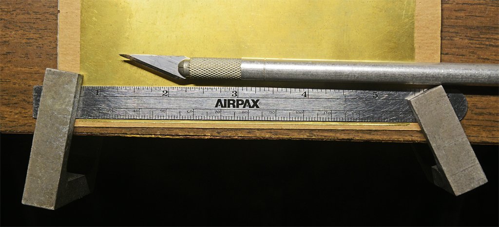
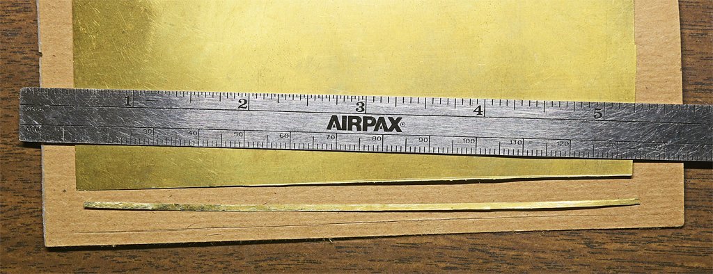
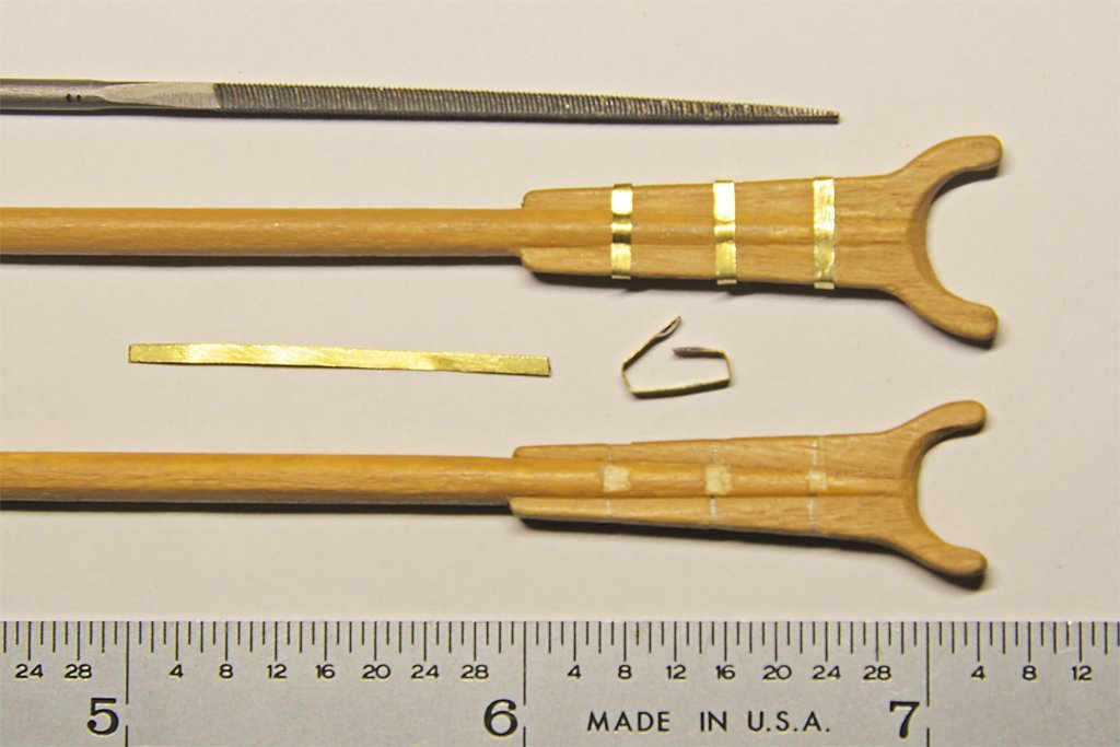
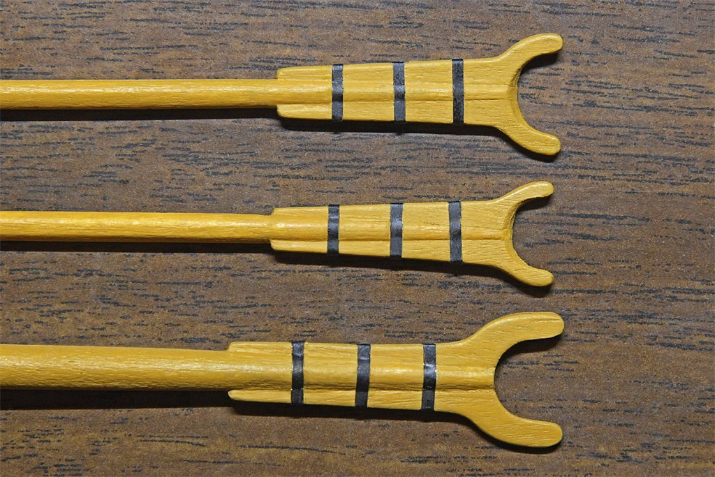
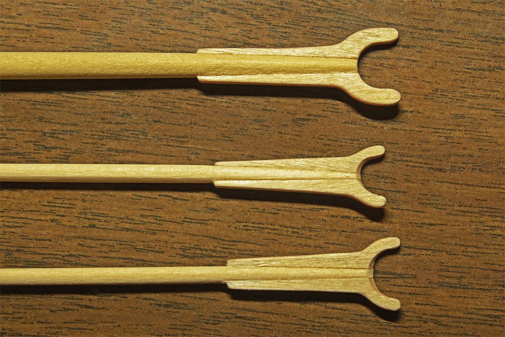
Here is a bit more work on the gaff and boom jaws. I thought I might drill through the jaws and spars edge on an insert a metal pin, but the 1/16 inch (1.6 mm) wood is pretty thin. I would have to hand drill straight with a pin vise for 1/4 inch (5 mm) or so without coming out through the upper/lower surface. The probability of doing that successfully a half dozen times or more seemed pretty low. I did add the metal bands around the jaws and spars, and that gives the assemblies enough strength. First I notched the jaw edges and spars slightly with a small square needle file to accept 0.050" (1.27 mm) wide 0.005" (0.13 mm) thick brass strips. I didn't blacken the brass first because there was a lot of bending that would just scratch it and I wanted to solder the ends of the strips to fasten them in place. The strips were formed around the jaws and removed so the ends were tinned. Then the metal pieces were slipped into place, clamped and the solder was reheated to form the bond. After this I used forceps and a tiny chisel point to crimp the strip down and around the curved spar. This produced a very tight fit around the jaws. I repainted the wooden parts with the straw color of the masts and allowed a bit of paint to flow under the brass where it would to "glue" the strips in place. Then the bands were painted with flat black enamel. The trick to working with thin brass to form it around something like this is to get very sharp bends around the corners. For this I used needle nose pliers to make the initial bends. Then I wrapped the piece around the edge of a 1/16 inch (1.6 mm) piece of metal and used a small hammer and anvil to make very sharp bends. Here is how I get the 0.050 inch (1.27 mm) brass strips (or strips of any desired width). This will work with brass sheets as thick as 0.010 inch (0.25 mm) thick. First I use calipers to scribe a light scratch the desired distance from the straight side of the brass sheet. This is then used to align a steel ruler along the scratch. The ruler is clamped into place, with the clamps also holding the brass sheet tight on top of a sacrificial cutting surface (scrap cardboard). Then an ordinary #11 hobby knife is run along the edge of the ruler, pressing down firmly, to cut into the metal (don't use a new blade). After seven or eight passes the blade will cut through 0.005 inch brass. About twice as many passes are needed for 0.010 inch brass. The knife produces a slight raised edge along the cut. You can remove this with a file or sand paper. With this trick you can have any dimension brass strips with only a stock of thin brass sheets. Of course it will work with other soft metals (aluminum, lead alloys, etc.) but I wouldn't try it with ordinary steel thicker than 0.001 - 0.002 inch (0.025 - 0.05 mm). I wouldn't try cutting stainless steel of any thickness this way. Some modelers use a paper cutter to cut thin metal, but unless you can clamp the sheet firmly to the cutting board the cutter edge will try to turn the sheet and you will get an uneven width piece with a curved edge (been there, done that).
-
Rigging the Endurance by Occre
Dr PR replied to David Enghauser's topic in Masting, rigging and sails
David, The Endurance was essentially a three masted topsail schooner. Read through this article to learn about schooner rigging. It discusses two masted schooners, but the Endurance just had a third fore-after mast similar to the main mast in these drawings. https://modelshipworld.com/topic/25679-topsail-schooner-sail-plans-and-rigging/?do=findComment&comment=750865 The rigging names will be similar for the spar and sail rigging, and the kit belaying plan should show where each line is belayed. Keep in mind that no two ships were the same, and even the same ship changed with time. So if you don't have the exact plan for the precise date you are modeling you will have to make a "best guess" for your model. -
George, Rothschild! Brother. You move in different circles from me! The black metal would be very nice for most ship modelling (and model railroading) purposes. I guess if I want the black metal foil I'll have to move up to more expensive wines. Many (30-40) years back I used the small metal tins that held tubular glass fuses. I'm not sure what alloy it was, but some type of steel. It was very thin and easy to cut and form, and it soldered OK. Now everything seems to come in plastic.
-
John, I don't know if I would call it a "fine" metal, but so far it has been in abundant supply. I guess it's greatest virtue is that it is soft and easy to work. Of course, that property rules it out for many jobs. I have noticed that the thickness varies quite a bit from winery to winery. And some companies are using plastic, so the metal seals may go the way of the wine cork.
-
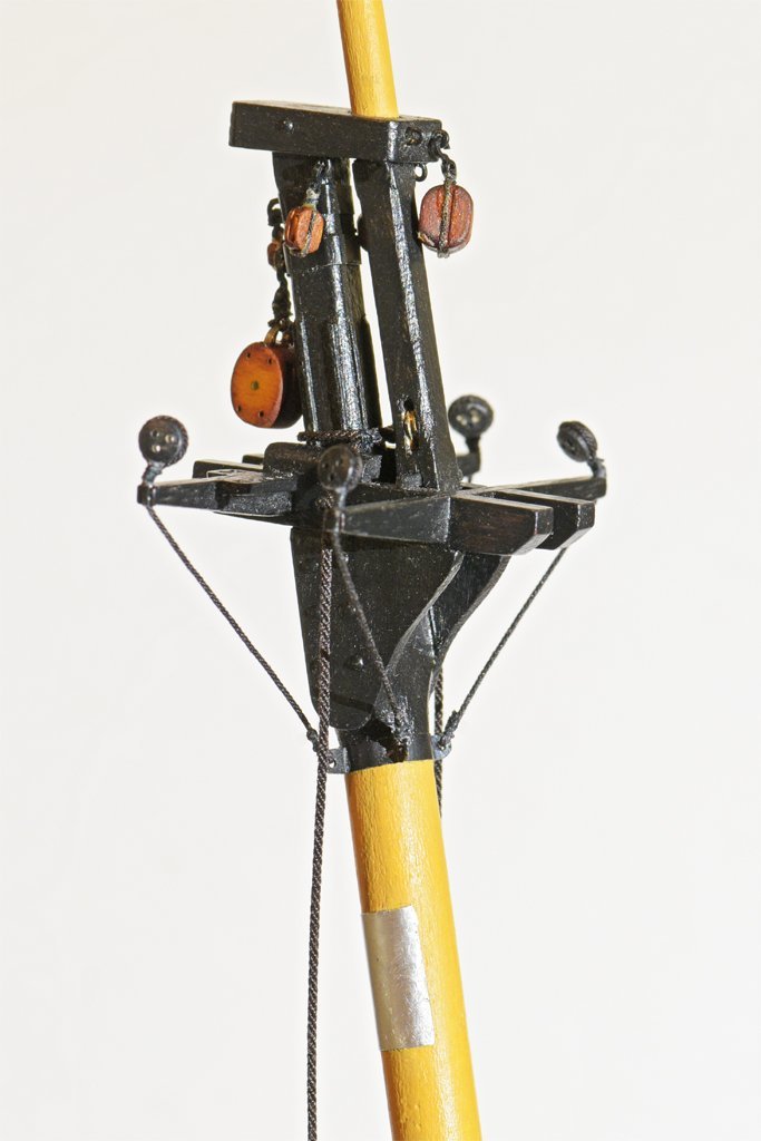
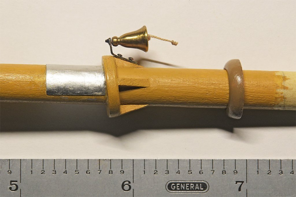
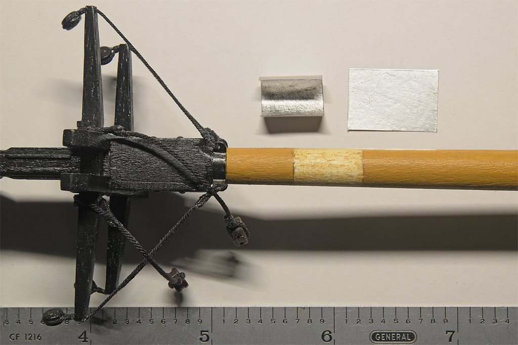
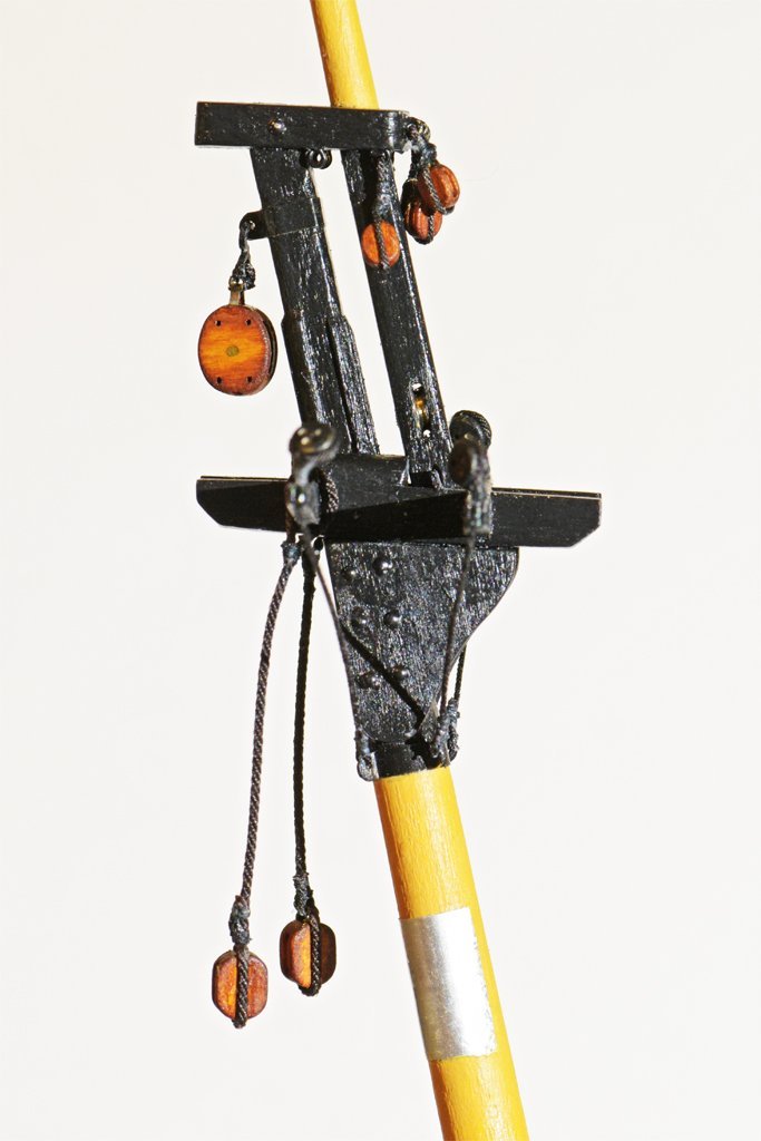
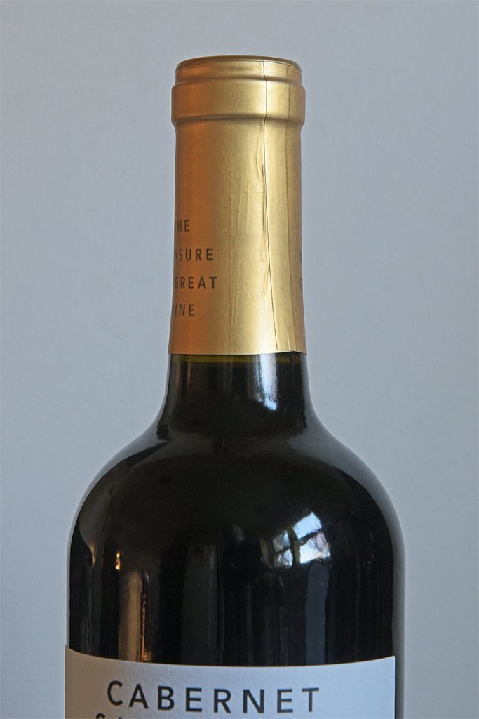
Some authors say that masts were protected from chafing by booms and gaffs with a metal plate. I decided to try this on this model. The catch was trying to determine the proper location on the masts without having the rigged gaffs in place. But after the gaffs were (mostly) finished I could measure the length of the throat halliard tackle with the gaffs in position. Then I determined the dimensions of the metal sheets. I searched through my metals stash for very thin material, and found some special metal sheets that were only 0.0035 to 0.004 inches (0.09 to 0.1 mm) thick. After the paint was scraped off the area the metal was shaped to fit around the mast and then glued (Duco cement) in place. After the glue dried and a bit of touch-up paint on the masts the gaff jaws were filed to slip over the metal plates. Here are photos of the fore mast and main mast with the metal in place. The metal plates wrap 3/4 of the circumference on the aft sides of the masts. I discovered that I made the main boom topping lift pendants too short, based upon my original drawings that showed the gaff hoisted too high on the mast. You can see on the right that the blocks hang down to about where the gaff will be. They should be somewhat lower so they don't bump on the gaff. Well, if you have done much scratch building you know that a lot of the work will have to be repeated! Could be worse!! Here is the boom rest on the main mast with the jaws of the boom in position. There is still a lot of work to do on the boom and gaffs. There are metal bands around the jaws, and I intend to drill through the jaws and mast and pin them together with wire for added strength. And there are several cleats, thumb cleats, metal bands and ring bolts still to be attached. And what was that "special metal" that I used for the chafing plates? Well, it is something I have in nearly unlimited supply and it is very easy to work with. But oddly, I do not recall ever using it before. You can see the original source here, around the top of the wine bottle. It is the metal alloy used to seal the bottle. Just cut it off and roll it out. I sanded the painted side to get better "tooth" for the glue to adhere to. Cheers!
-
Roger is right about trying to nail or screw into the edge of plywood. I think it is OK for bulkheads IF you are just going to use glue to fasten the planking. But if you will be using fasteners or treenails solid wood bulkheads will be better. I got my model aircraft plywood at the local hobby shop that had a lot of R.C modeling supplies. Unfortunately, the Internet and big box stores have starved it to death, as they have also done to our local camera shops.
-
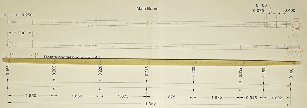
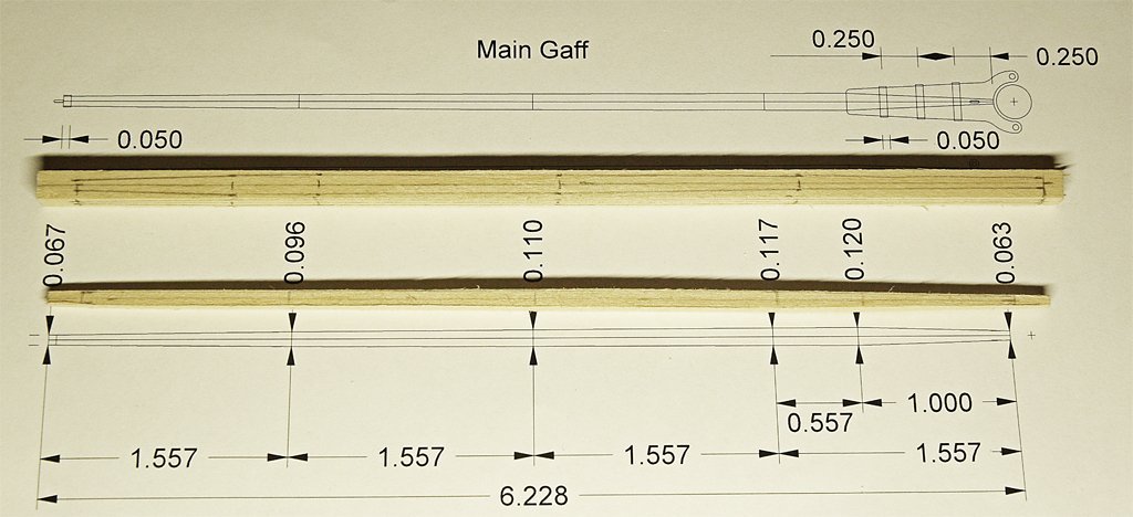
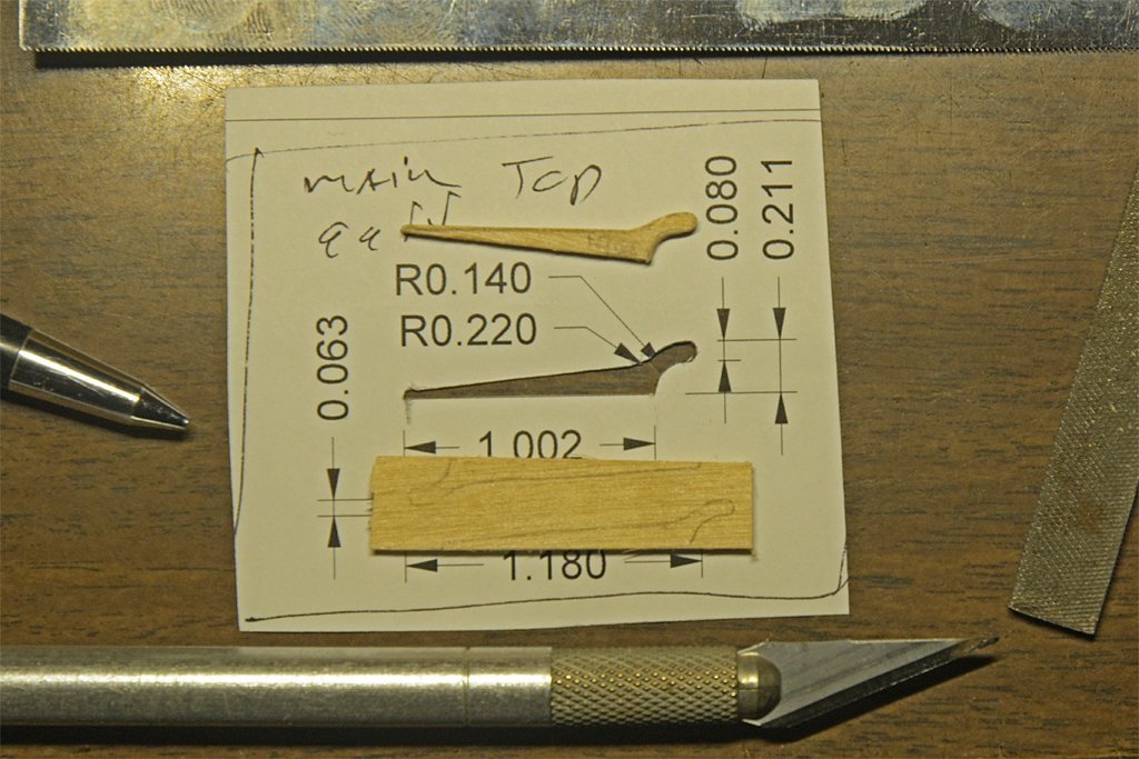
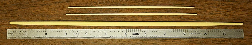
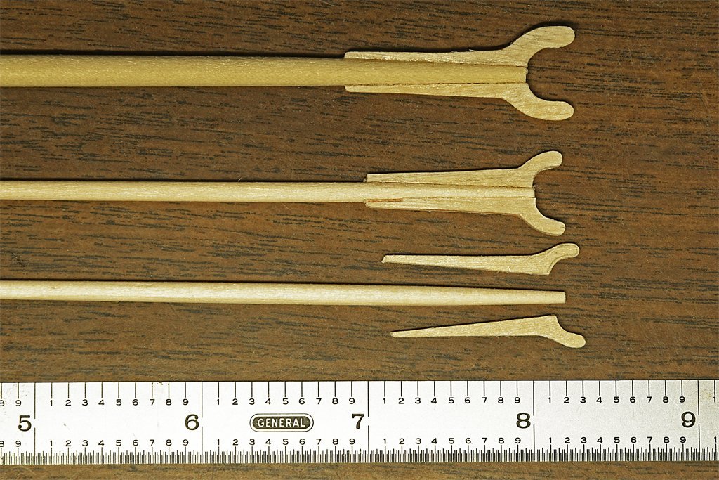
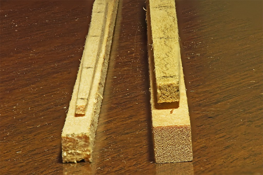
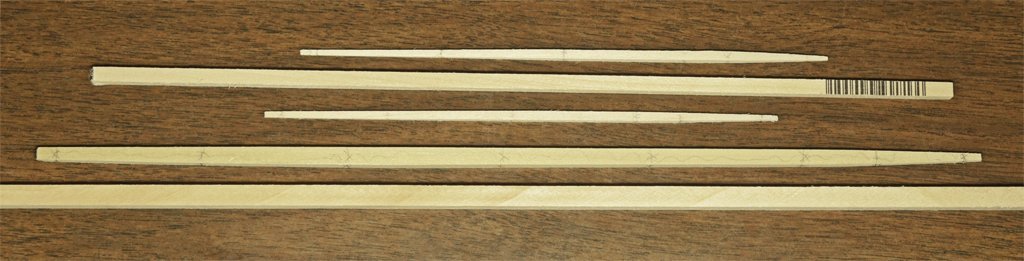
Before I can finish the rigging on the mast tops I need to check some dimensions with the gaffs and boom. So making these was the next project. I took spar lengths from the model rigging plan and created a 2D CAD drawing using the prototype spar dimensions from Marquardt's The Global Schooner. I think these dimensions are probably more accurate for schooners than the square rig spar dimensions from other books. The parts were carved out of square dowel stock. If you haven't tried making masts and spars this way it is something to consider. It is very simple and quick. First I drew the spar outlines in pencil on the faces of the square dowels. Then I used a small plane to remove most of the excess material - this produces a lot less sanding dust than trying to just sand the stock down to size. The final shaping was done by sanding on coarse sandpaper. After the square cross section spars are done the edges are shaved off with the plane to create an octagonal cross section. With small spars like these I them just finished rounding the pieces with sandpaper. The photo above shows the rough shaped spars and the stock they were carved from. Below are the rounded spars. Next were the jaws for the boom and gaffs. I printed the drawing of the spars and cut out the part with the jaws. After cutting out the jaw pattern I used it as a template to pencil in the outline of the jaws on thin pieces of plywood. Again, this was made by gluing two pieces of 1/32 inch (0.8 mm) model aircraft plywood together and allowing the glue to harden overnight. It is easier to carve small details without the wood breaking with the plywood than with just a thin piece of wood. Two of each jaw pattern were made. However, tough as the plywood is, one piece broke and I had to make another one to finish the job. The pieces were glued together with Duco cement. This is an acetone based solution of nitrocellulose. It dries quickly and sets in a few seconds. I followed the instructions and coated the mating surfaces with glue and let it dry, Then I added a new layer of glue and clamped the pieces together. It set firmly in less than a minute and made a strong bond. After curing overnight I sanded the parts and coated them with shellac to seal the wood. I will add metal bands around the jaws and spars, and some additional details later. But for now I can use the pieces to measure the length of some of the mast rigging (throat halliards in particular).
-
This is an excellent choice for a first scratch build project. The hull doesn't have complex curves and there is not an extreme amount of superstructure or rigging to deal with. The 1:35 scale allows a tremendous amount of detail, and there is a large amount of military tank and vehicle parts and figures available that might be useful. I have see a couple of beautiful 1:35 scale PT moat models. Personally, if you are building out of wood I would use 1/8 inch model aircraft plywood for the frames and keel. This way you would need only a sheet or two of the plywood, and would be working with only one type of material. I like the good quality aircraft plywood because it doesn't split along the grain like some woods tend to do. This is especially true for small thin parts that must be hand shaped a lot. You could use the really thin (1/64") model aircraft plywood for the hull plating - it does bend pretty much like paper. But is is fragile, and it would be easy to poke holes in the thin stuff between bulkheads. I guess planking would be the way to go if you use wood. Another way to build it would be to use styrene for the hull keel, frames and surface. You can cut paper templates and use these to shape the plastic. You can heat it with a hair dryer to get it to curve in the right places (don't over do it though).
-
Best paint for wooden ship models
Dr PR replied to Hsae's topic in Painting, finishing and weathering products and techniques
Bob, I usually remove the masking tape before the paint dries to avoid lifting the dry paint. However, this is tricky, because it is a guessing game to decide when the paint is dry enough but not too dry. -
The fuzz on scale rope should also be to scale. If the fibers on 1:1 rope are 0.001 inch (0.025 mm) - 5 times the diameter of a human hair - the scale fuzz would be 0.00002 inch (0.0005 mm) at 1:48 scale. You would need a microscope to see them. From a normal viewing distance the ropes on a scale model would have no visible fuzz.
-
Best paint for wooden ship models
Dr PR replied to Hsae's topic in Painting, finishing and weathering products and techniques
One of the advantages of acrylic paints is that they dry quickly - or so we are told. I began painting (artistic) about 65 years ago with oils, and it was frustrating having to wait weeks for them to dry. I was enthusiastic about working with "fast drying" acrylics. They do dry relatively quickly (an hour or less) so you can apply a second coat. It is best to apply several thin coats rather than one thick coat. However, they do not harden until a week or two after application. Before this you can scrape them off with a finger nail! Here is a trick I learned on the forum for using tape. Paint a part of the hull (upper/lower) with the appropriate color and let it dry thoroughly. Then apply the tape over the painted part. Now paint over the edge of the tape with the same color. If anything bleeds under the tape it will be the same color as under the tape and, therefore, not a problem. This will seal the edge of the tape so nothing else can bleed under it. Then paint the other part of the hull. If you have a slight raised edge when the tape is removed carefully scrape it with the edge of a hobby knife to remove the raised edge. I suggest trying this first on something you don't care about because it requires a bit of practice to get the technique down. You can also gently sand the raised edge and then apply a clear coat over it to get a smooth finish. -
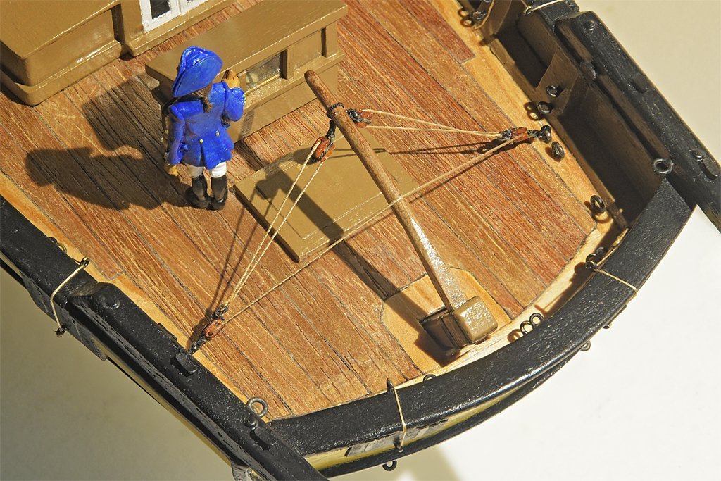
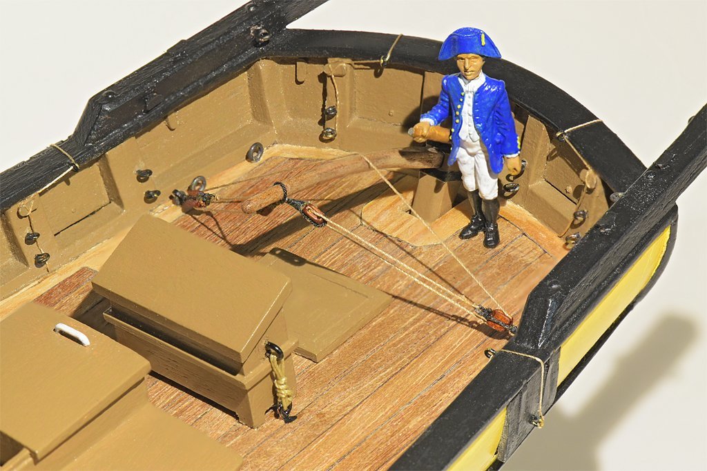
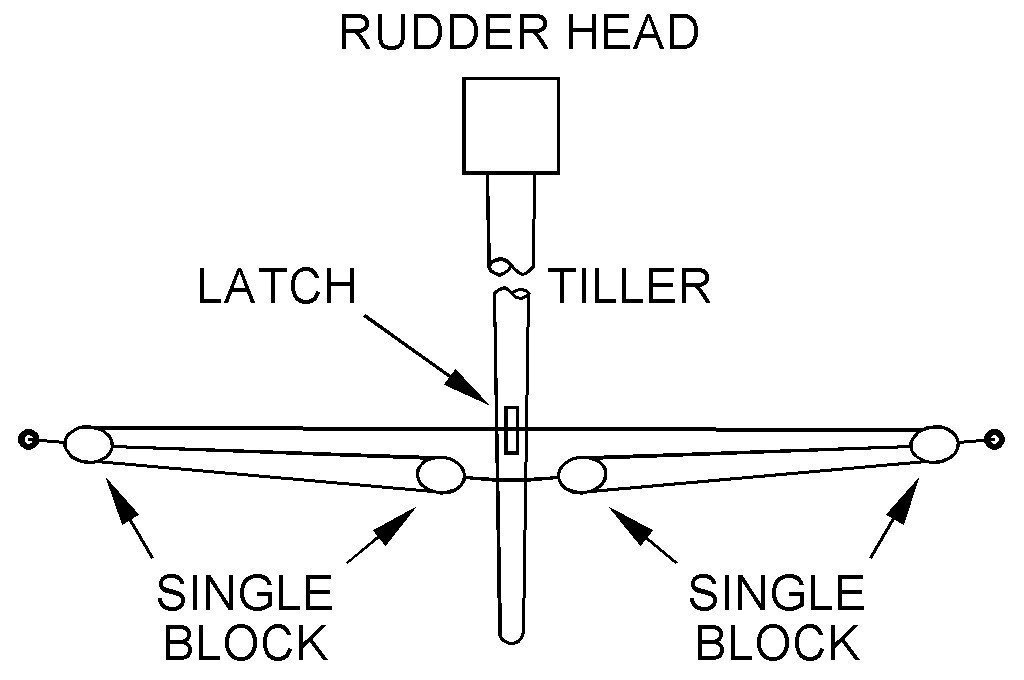
I have installed the starboard anchor. This anchor is secured to the rail with the shank painter and the stopper ropes. These lines are secured to timber heads on the rails and belayed to cleats on the bulwark. When secured this way the anchor cable is detached and stowed, and the cat tackle is not attached. I haven't installed the port anchor yet - it is just sitting on deck for size reference. I am planning to have it in a position supported by the fish davit and fish tackle attached to the fore tackle. The anchor cable will be attached and the head of the anchor supported by the cat tackle attached to the ring. This would be the configuration for hoisting the anchor up to the position on the rail while weighing anchor. I have discussed this rig in this link: https://modelshipworld.com/topic/27410-small-ship-anchor-handling/?do=findComment&comment=787942 I have also been working on the tiller tackle for steering the ship. I should say that this configuration is a bit speculative for the early 1800s. It is in use today on the vessel Lady Washington, but I do not know when this exact arrangement came into use. It was common to have tackle attached to the tiller as far back as the early 1700s. Some models and drawings show two separate tackles attached to port and starboard sides, with the falls led forward and belayed. But I have seen photos of a model of a topsail schooner from the early 1800s with this rig, although I have no idea how accurate it is. The tiller tackle serves two purposes. First, it acts as a shock absorber to absorb forces generated in following seas when waves slap the rudder and swing the tiller. The friction of the ropes running through the blocks and the mechanical advantage of the tackle reduce the rate of the tiller swing, making it easier for the helmsman to control the tiller (and get out of the way as it swings). The tackle could also be used to steer the vessel by hauling on the appropriate fall and slacking the opposite. The rig shown here accomplished both tasks. When the helmsman pushes on the tiller line feeds from the tackle on one side and into the tackle on the opposite side. This reduces the rate the tiller swings, but also give mechanical advantage to the helmsman against the forces of the waves. In modern rigs a latch is attached to the top of the tiller where the line crosses. Pressure on the latch slows the rate of tiller swing, and if the latch is secured hard on the line it serves as an "iron mike" to hold the rudder at a steady angle.
-
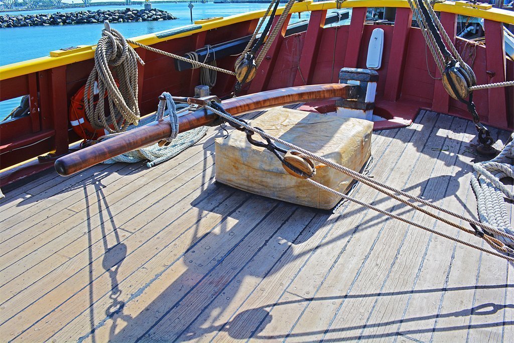
That isn't always the case. There is more discussion here: https://modelshipworld.com/topic/34708-tiller-tackle/#elControls_989249_menu The tiller tackle arrangement shown below is sometimes used. The latch allows the rudder to be secured at a desired angle - sort of an "Iron Mike" for holding course. The vessel is the Lady Washington. The tiller tackle in Steve's photo does accomplish two things. First, as the rope slides over the notch in the top of the tiller handle there is friction to slow the tiller movement. Pressing down on the rope would increase friction. There are mechanical devises available today to actually control the friction better, allowing the helmsman to move the rudder but still resist movement caused by water action. Secondly, the friction in the tackle as the ropes run through the block act as a damper to minimize sudden movement of the tiller. It acts as a shock absorber. I am still trying to figure out when this arrangement first came into use.
-
Focus Stacking
Dr PR replied to Dennis P Finegan's topic in Photographing your work. How to do this.
Very good explanation. Another issue, especially with macro lenses, is that as you change focus the area included in the photo changes size a bit. So any particular object will be different sizes relative to the overall frame size in different images. Photoshop has a "Edit/Auto-Align Layers" function that resizes each layer so objects common to all are the same size - and maybe "stretched" a bit to the same overall outline. But the result is that the outer edges of the stacked photos can be blurry. I always back off enough that the photo frame is a bit larger than optimal, and crop the edges in the final picture. Photo stacking isn't perfect, but you can get extraordinary depth of field if you use it correctly and don't mind doing a bit of post-processing touch-up. -
Focus Stacking
Dr PR replied to Dennis P Finegan's topic in Photographing your work. How to do this.
I use an older version of Photoshop (CS5) and the focus stacking works only marginally. It is especially bad where a near object, like a rope, passes in front of a more distant object. The distant object will be blurred slightly on either side of the closer object. I have to do a lot of touch up, but I get acceptable pictures. My cameras don't do focus stacking internally. That's something to look for in future purchases. -
Very nice work!
-
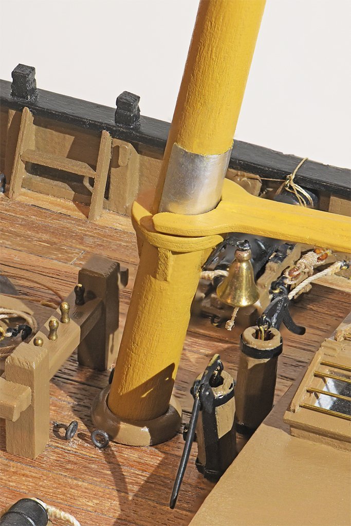
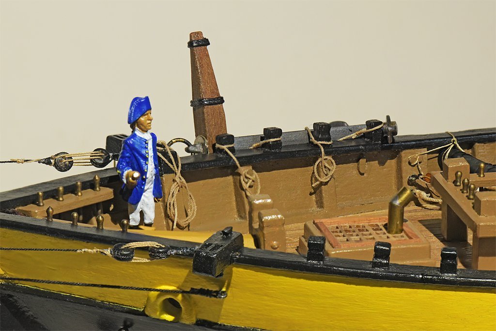
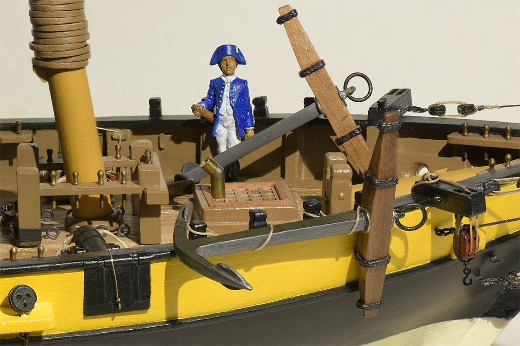
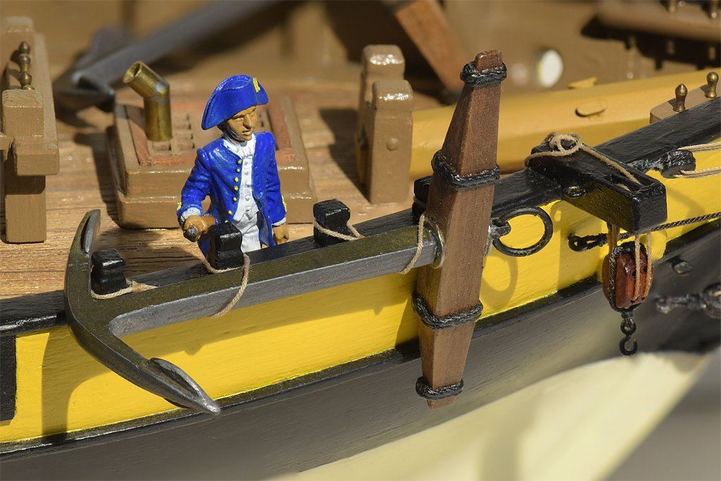
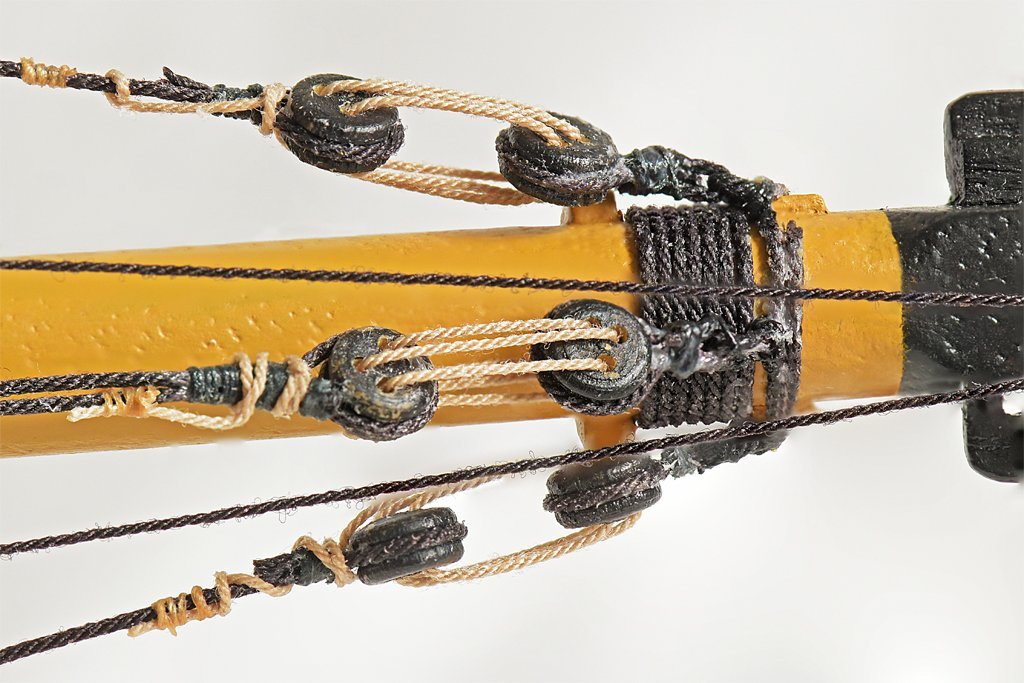
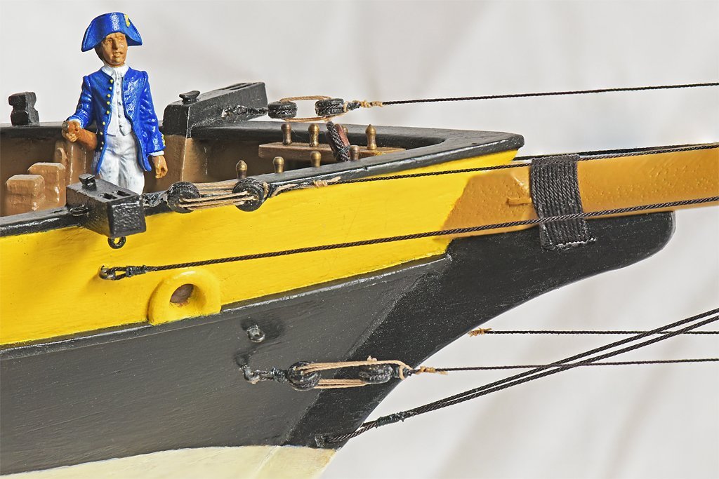
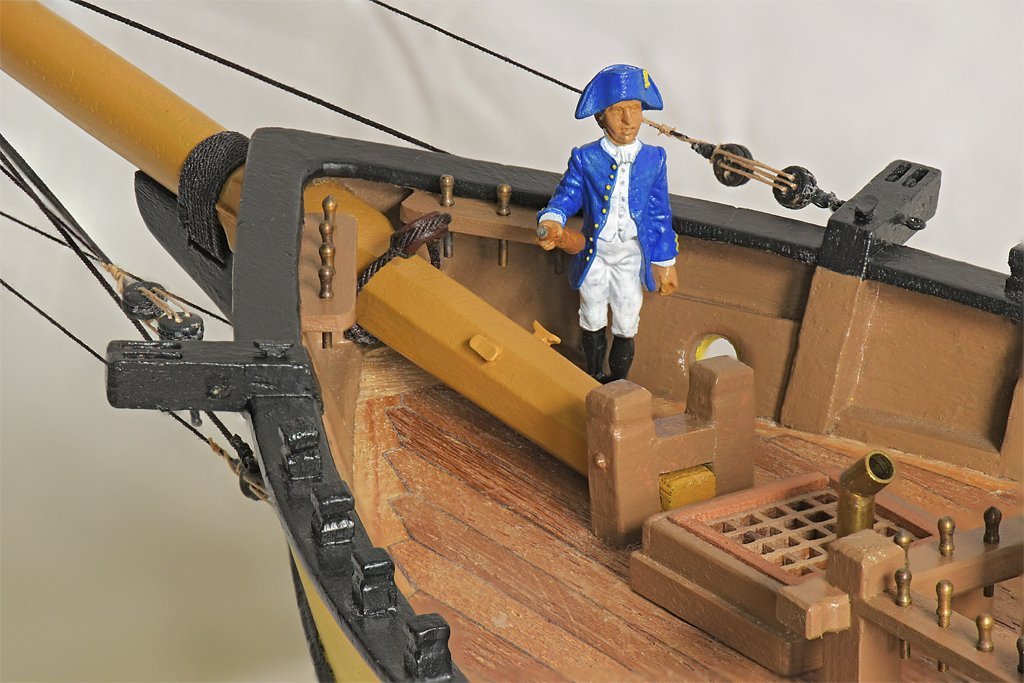
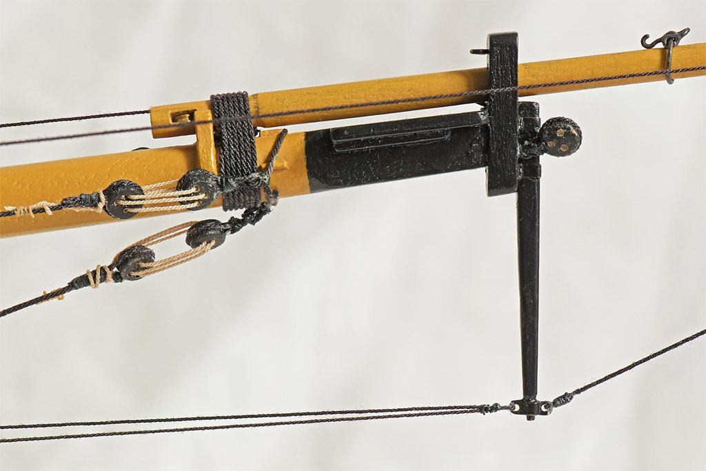
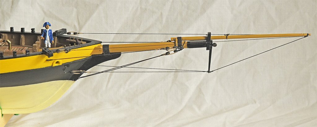
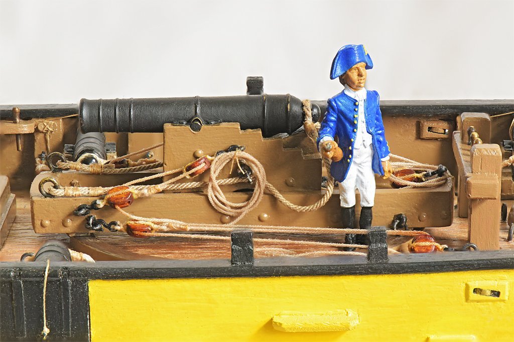
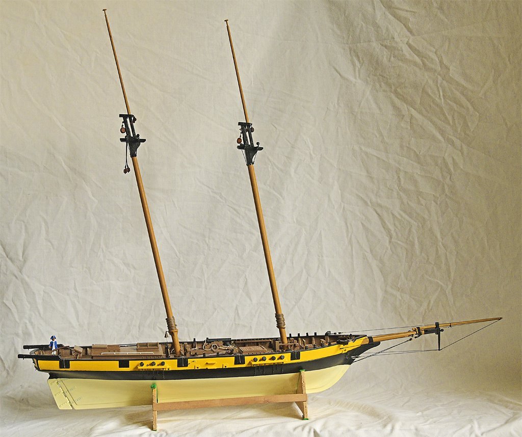
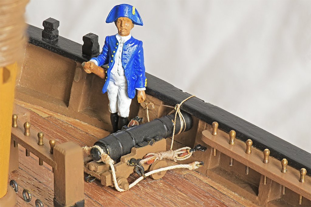
I have finished the bowsprit standing rigging. There are probably as many variations on this as there were ships, but the configuration I am using was found on some smaller vessels. You can see the octagonal bowsprit housing in this photo, with the heel stepped between the two bits. I added two cleats for belaying miscellaneous lines. I had to wait until the bowsprit was installed to add these because they wouldn't pass through the hole in the bow. The open heart for the forestay also could be installed only as the bowsprit was being put into place. I found this Amati cast metal figure on line, and use it to show the scale. However, it is a peculiar size - 35 mm high. At 1:48 this makes the fellow about 5.6 feet tall (1,7 meters) with hat, or about 5.2 feet without the hat. So it is really about a 1:55 scale figure, assuming the fellow is 5' 6" tall (1,7 meters). Why would anyone make a 1:55 scale figure?? Either people were shorter 200 years ago, or perhaps this is a midshipman! Perhaps it is Napoleon's cousin? Anyway, it does give a general idea of the size of things. I would like to find an actual 1:48 scale (O scale) figure 35-38 mm without hat or 37-40 mm with hat. The gammmoning fastens the bowsprit to the knee on the stem or head of the ship. The jib boom guys attach to the catheads with 3.5 mm deadeyes. Some vessels used hearts and others used thimbles. The lanyards are half the diameter of the guys or shrouds and are belayed by taking a few turns around the guy and securing with seizing. The bowsprit shrouds (port and starboard) are secured to eyebolts below the catheads. The eyebolts below the hawse openings will secure the jib stay (stbd) and preventer (port). Below these the martingale backstays (P & S) attach to eyebolts with deadeyes and lanyards. The bobstay is doubled, passing through a hole in the stem and secured with seizing. The bowsprit head is the belaying point for several lines. The martingale (dolphin striker) is attached to the bowsprit cap. At the bottom end is a metal fitting where the two martingale backstays are secured on the aft side (left in the photo). On the fore side the aft end of the martingale stay is belayed. The other end has an eye looped around the end of the jib boom. You can see the traveler on the jib boom and the sheave in the base of the boom for the jib boom outhaul (not rigged). The deadeye on the starboard side of the front of the bowsprit cap is for the foretop stay. The flying jib stay (traveler outhaul) tackle will attach on the port side of the bowsprit cap. The most complex part of the rigging is the bobstay collar. This has three deadeyes attached to it. The port and starboard deadeyes are for the bowsprit shrouds. The center deadeye is for the bobstay. I made the collar a bit too loose. It is supposed to fit tight in front of the three thumb cleats attached to the bowsprit, but you can see that it actually rides over the two thumb cleats on the sides of the bowsprit, and is hooked in front of the top one only. Here are a couple more pictures to show scale, with the 12 pounder pivot gun on the left and a 6 pounder carriage gun on the right. And finally, a photo of the entire ship as it stands today. The masts have not been installed permanently. I am still working on some of the rigging that will be easier to attach with the masts off the ship.
-
The books say to just lash the free end to the nearest loop of the gammoning with seizing. That is what I did on my model.
