

abelson
-
Posts
467 -
Joined
-
Last visited
Content Type
Profiles
Forums
Gallery
Events
Everything posted by abelson
-
 Thanks.
 -
Thanks.
-
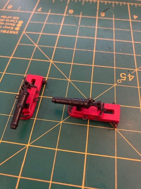
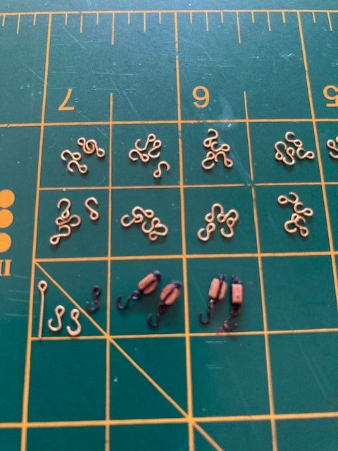
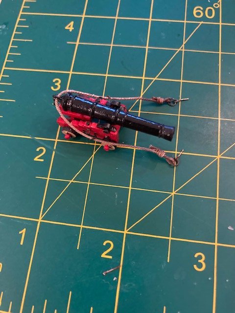
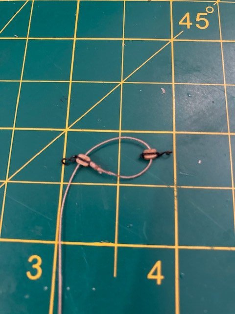
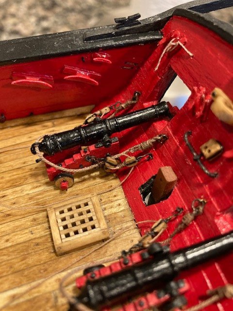
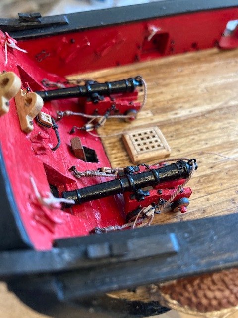
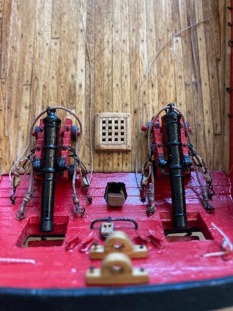
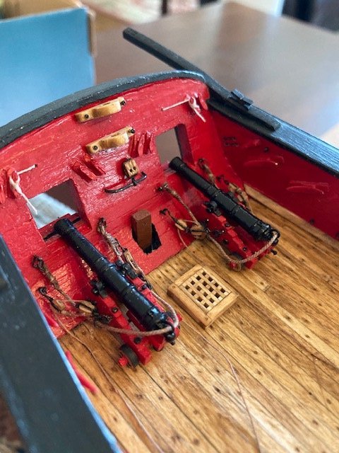
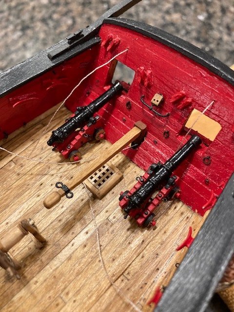
Rigging the Carronades: Note: The instructions say to use tan .028” rigging for the breech ropes – the kit doesn’t come with this size line. The closest kit supplied line is 0.021”. I ordered some .025” rigging rope from Syren. I didn’t like the quality of the cotton/poly .008” tan line, so I also ordered some .008" rigging rope from Syren. First, I cleared all the deck fittings. Then, I started making the tackle hooks from 1/32” brass eyebolts. I flattened the end of each hook using a punch and tapping it twice with a hammer against my work bench vise; then I blackened them. I decided to add the breech ring to the sides of the upper sled – I used 3/32” eyebolts (MS0427). For the tackles, I used the 3/32” (2mm) single rigging blocks furnished with the kit. I stropped the hooks to the blocks with 0.008” black line – not an easy task considering how small the blocks are. I made up enough for one-half of the carronades. I decided to rig the long guns first, starting with the breech lines. I followed Dubz build log (page 30) for making the breech line knots, although, I didn’t follow his instructions for the seizing. I kept the seizing simple by just wrapping the seizing rope around the loop 4 or 5 times. One problem I had with making the knots was the CA glue – I found that just a small drop of CA bleeds into the rope, making it stiff and discoloring it. The discoloration, however, does give the rope an aged look. I rigged the breech lines with the cannons off-ship. The breech lines aren’t perfect but I’m happy with the how they turned out. I glued the cannons on-ship and glued and inserted the breech line eye bolts with split rings into the stern. Next, I made up the tackles with .008” rigging rope. In seizing the rope to the tackle block I had the same problem with the CA glue. I’m not completely happy with the tackle lines because the blocks are too close together. This is due to the length of the hooks. This part of the build is very challenging, at times frustrating, and requires a lot of patience. Persevere. With the long gun rigging complete, it’s on to the carronades.
- 157 replies
-
- 3
-

-
- model shipways
- syren
- (and 1 more)
-
Nice work on the long cannons - they look great. I had the same problem with the laser cut pieces.
- 950 replies
-
- 1
-
-
- syren
- model shipways
- (and 1 more)
-
Thanks. Progress will be slow now that I'm onto the carronade rigging.
- 157 replies
-
- 1
-
-
- model shipways
- syren
- (and 1 more)
-
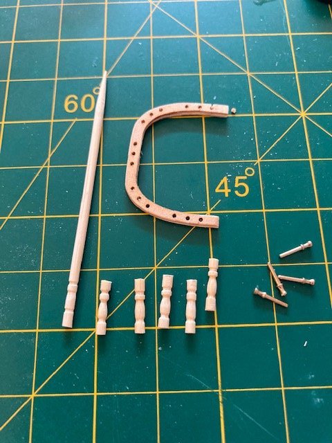
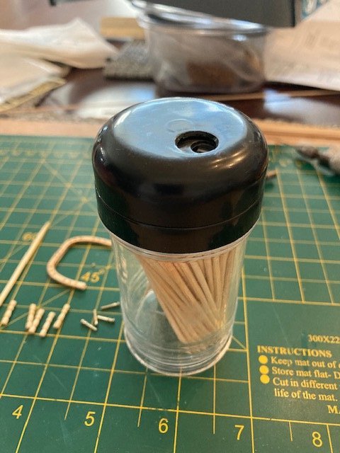
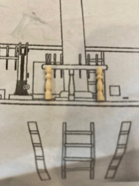
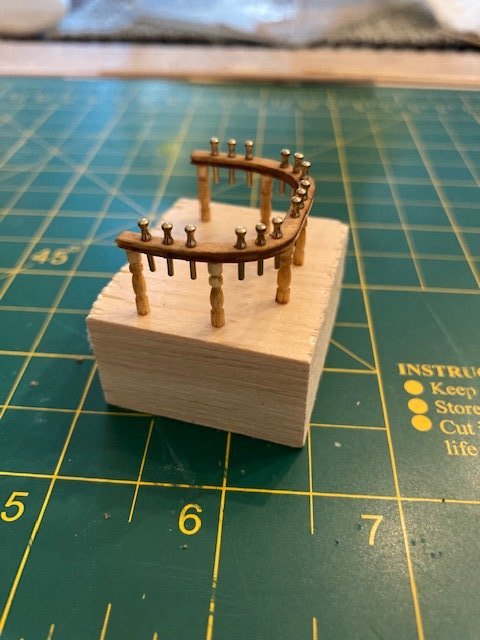
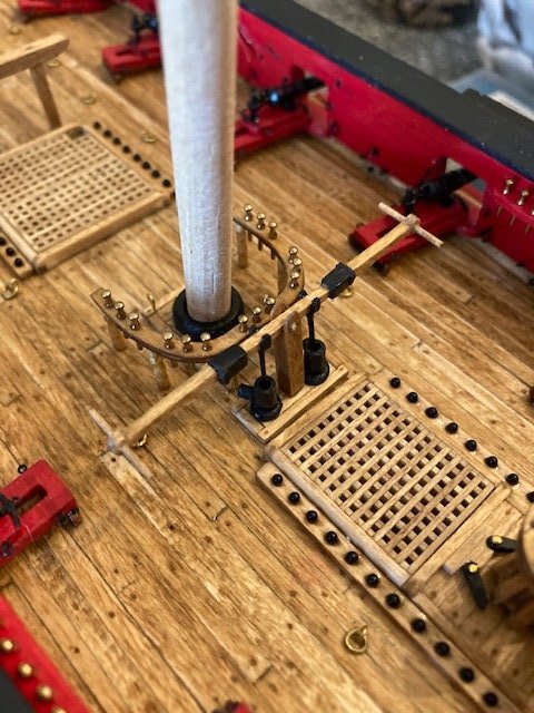
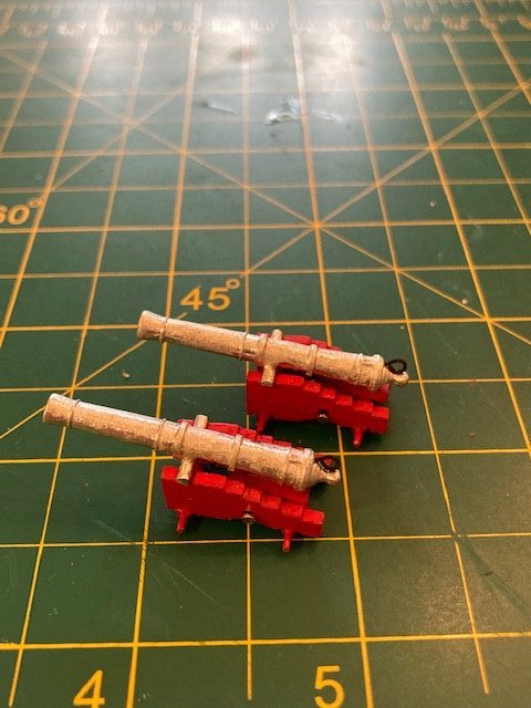
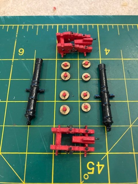
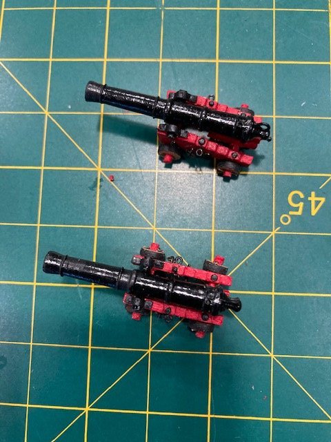
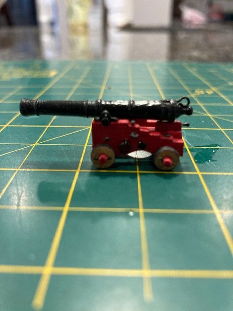
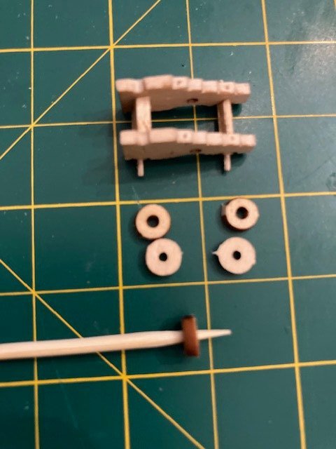
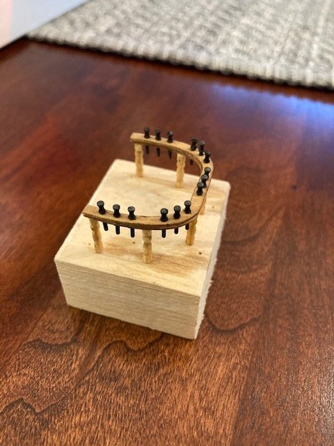
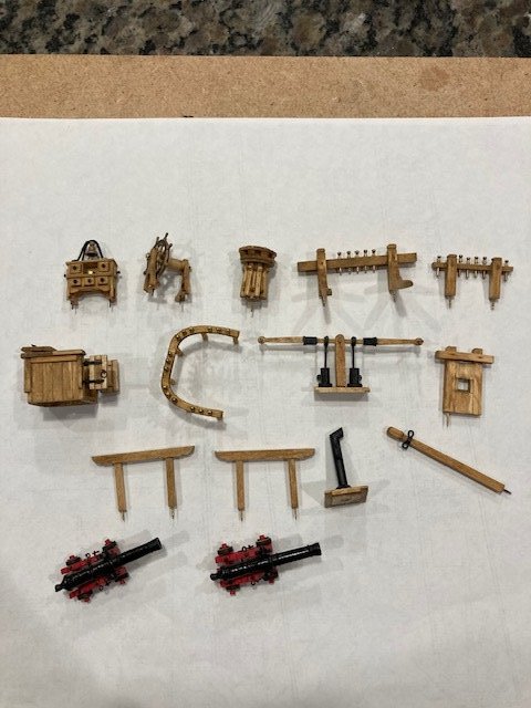
The main fife rail: The fife rail is very fragile. I had a difficult time rounding the edges of the 1/32” thick laser cut pieces. Each one broke. I was able to glue them together, however. To align them, I inserted brass pins in the belaying pin holes. I was able to create the double beaded detail with a file. This might be a better approach than trying to round the pieces before gluing them together, although, the inside bead is difficult to create. I had a bit of a snag with the fife rail. While reaming the holes for the belaying pins several pieces split and separated from the rail. I was able to glue them on. I dreaded making the fife rail legs but, alas, I found some wooden decorative toothpicks that I had laying around the house that were just the right size. I filed and sanded the decorative end of the toothpick somewhat to simulate the profile of the legs shown on the plans. I cut them and filed/sanded them to the same length. They’re brittle, so I decided not to drill holes for pins. This might be problematic when the time comes to belay rigging to the fife rail – time will tell. I couldn’t recall where I bought the toothpicks so I googled toothpick dispenser on the internet and, low-and-behold, I discovered a picture of the same dispenser. It’s called Bradshaw Good Cook Toothpick Dispenser, available at Bed, Bath & Beyond. I glued the legs to the fife rail, stained the assembled fife rail, and blackened the belaying pins. This completes Chapter 13. Jumping back to Chapter 12, I completed the 12 pounder long guns and carriages. I removed the char from the carriage brackets, axles, transom and bolster pieces and assembled them. I rounded the axle extensions. This was a mistake, as I found the pre-drilled holes in the trucks (wheels) are larger than the ends of the axles. So, I added faux axles to the wheels by inserting a wood dowel in each wheel. I drilled a hole in each dowel for a cotter pin. I used 22 gauge wire for the pins. BTY, as the instructions say, the front wheels are slightly larger than the rear wheels. The difference is not immediately obvious on the laser cut sheet, but they are marked Front and Back on the laser sheet. So, make sure to put the slightly larger wheels on the front. My laser cut pieces were cut on an angle. I had to sand them to even them out, which made them slightly smaller. Also, because of the angled cut, the holes are larger on one side than on the other (see photo). For the quoin handle, I used a brass belaying pin left over from my Rattlesnake build (47 years ago). I filed the cannons to remove some flash and drilled a hole in the end of each cannon for the 1/16” eye bolt for the breech line. To complete the cannons, I added the two eye bolts on each side of the gun carriage, one eye bolt on the rear axle, the cap squares that secure the cannons, and some rivets to the carriage for added detail. This completes the deck fittings. Except for the hatches, gratings, and shot racks, none of the deck fittings have been permanently attached. Now it’s on to rigging the carronades but, first, clear the deck.
- 157 replies
-
- 4
-
-
- model shipways
- syren
- (and 1 more)
-
Although I have yet to use it, pear wood definitely makes a difference in the crispness of the work.
-
Nice work on the planking. Particularly the stern. A big step completed. I like the stain, even if it will be covered. Seems like so a long ago that I was at that stage - time flies when your having a good time.
-
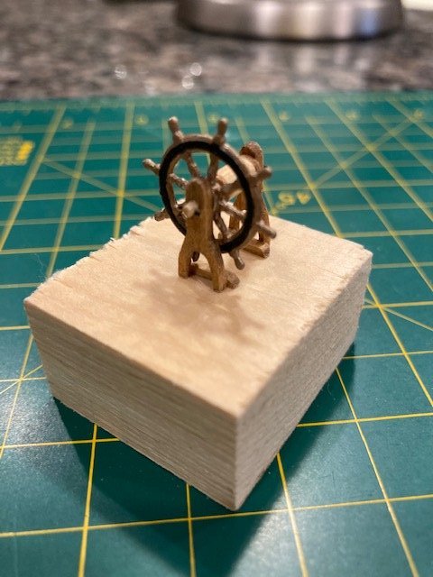
Thanks. The wheel is lead casting.
-
Nice work on the capstan. I share your anguish with the chocks. Some how we work through it and the end result is satisfying.
- 950 replies
-
- 2
-
-
- syren
- model shipways
- (and 1 more)
-
Great job rigging the carronades, it looks really professional. I'm still holding off that part of my build. I think you'll find the deck fittings more relaxing.
-
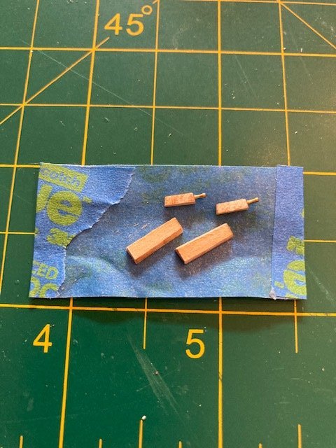
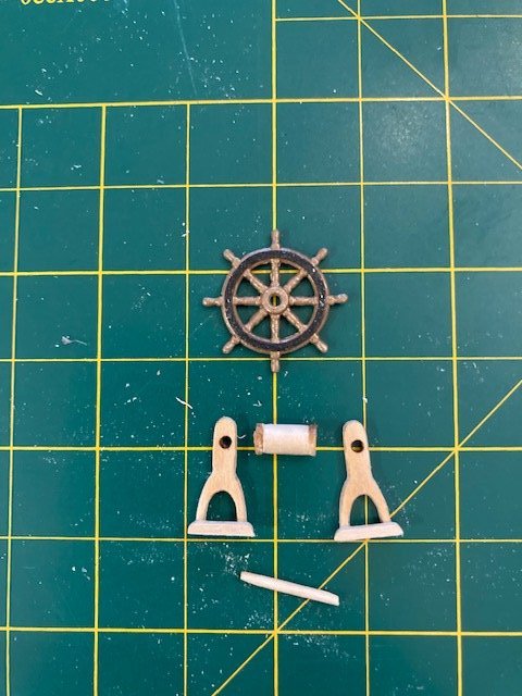
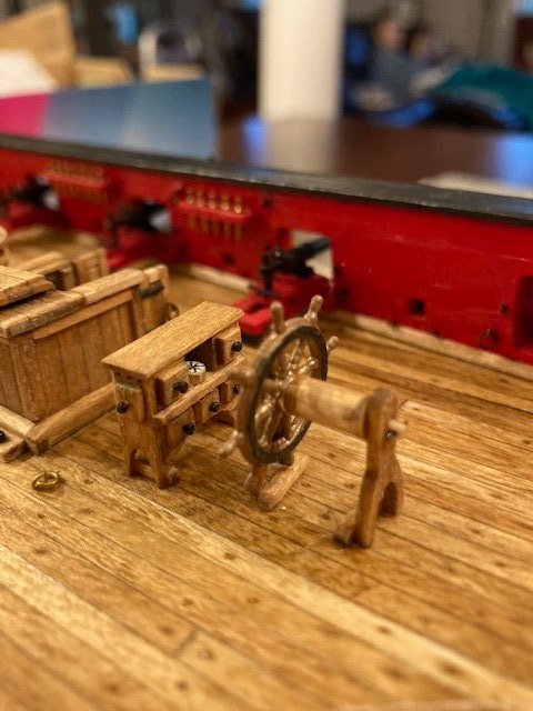
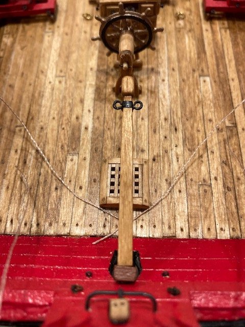
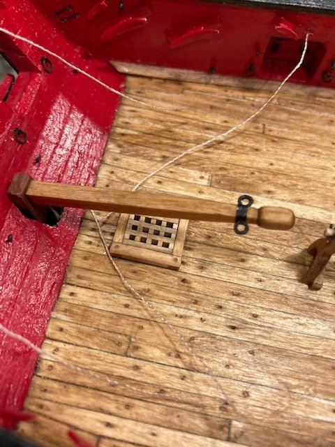
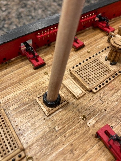
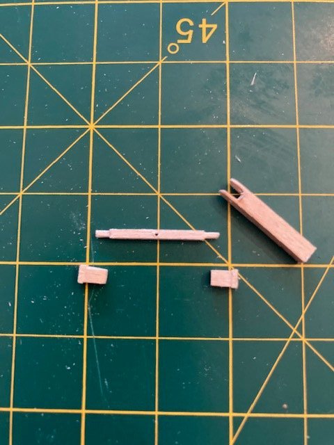
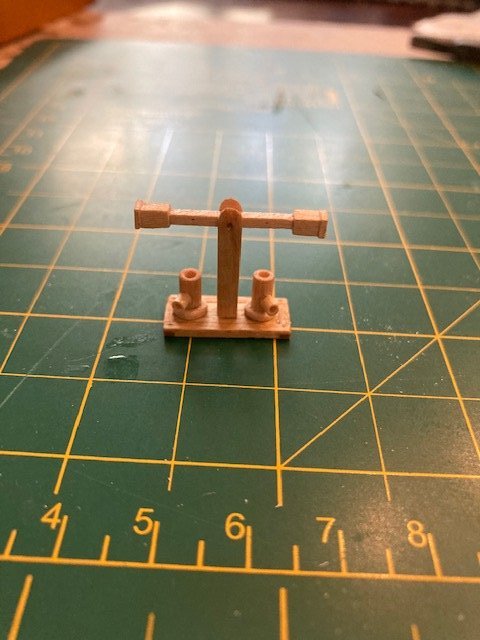
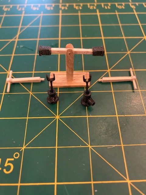
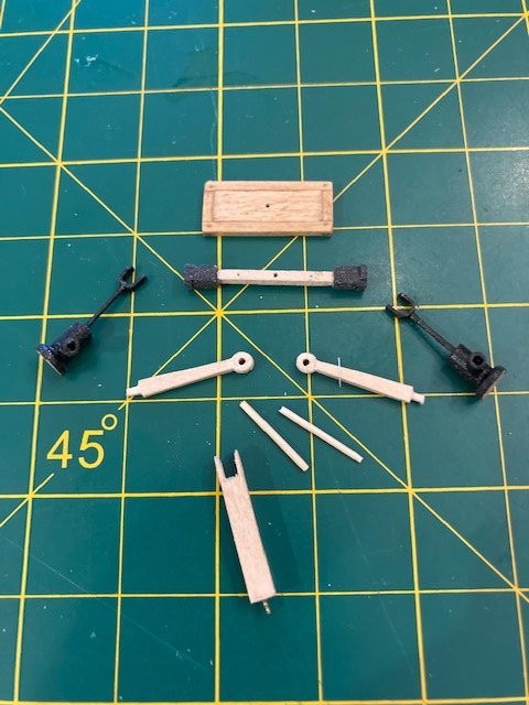
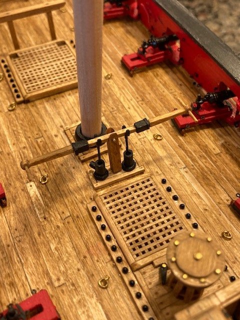
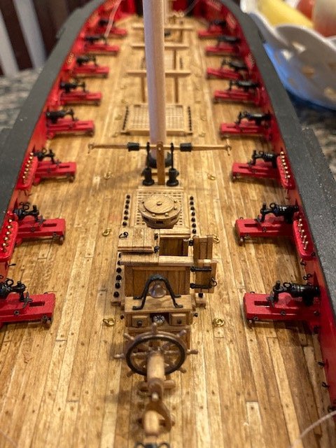
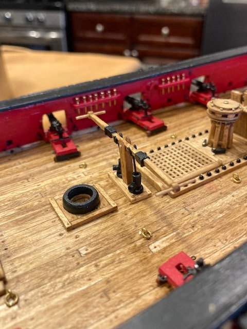
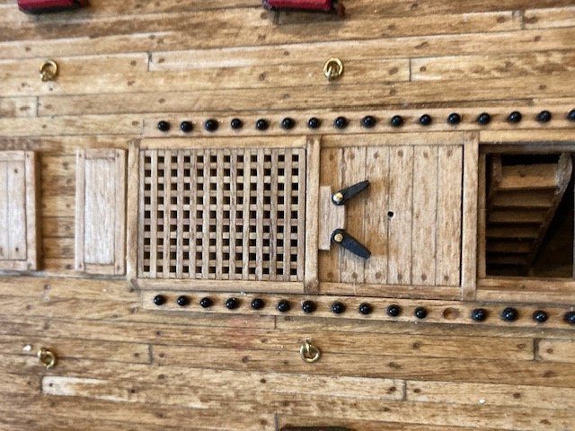
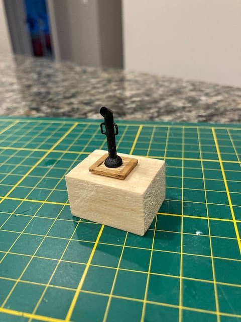
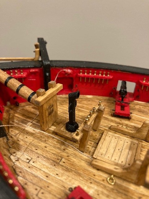
Continuing with the deck fittings, the ships wheel was built according to the instructions, except that I used wood dowels (made from a toothpick) instead of 22-guage wire to assemble the wheel. I used the kit furnished wheel – it had very little flash. The wheel was filed and all the laser cut wooden pieces were cleaned of the char and stained. I painted it with ME (MS4806) Antique Gold Trim paint and with black iron rings. The 1/32” x 1/32” battens will be pinned to the deck. Next, the tiller. The tiller was shaped from a 1/8” square basswood strip as per the instructions. For the split rings at the end of the tiller I used 1/16” eye bolts. I pre-drilled the tiller for inserting the eye bolts. I applied a piece of 1/16” black pinstripe tape around the tiller, punched a hole in it at each pre-drilled hole and then inserted the eyebolts. The tiller is pinned to the rudder. I completed the ship bell following the instructions. After a couple of failures, I was able to glue (CA) and bend the bell frame to the desired shape. I flattened the ends of the frame legs. I painted the bell Antique Gold and glued it to the frame – this was a little tricky. Lastly the bell frame was glued to the binnacle. I decided to drill the hole in the elevated square sections around each mast (the tenons). I had previously made these according to the instructions in Chapter 13. Drilling the holes turned out to be a disaster. I started with a small drill bit and gradually increased the bit size. But, on the way up, the wood planks split -UGH! I was able to salvage the coamings. I decided to re-make the tenons from 1/16” basswood board. I pre-drilled the ¼” mast hole and then cut the tenon out. I filed and sanded the tenon to fit inside the coamings. To simulate planks, I cut lines across the raised sections from port to starboard and then ran an awl across the cut line. I simulated tree nails by drilling a 55mm hole at the edge of each simulated plank and filled them with Minwax Golden Oak putty. The tenons were then stained. I did make one miscue, however. The grain on the wood of one tenon runs aft to stern instead of port to starboard. They’re not perfect and, once the mast coats are added, I don’t think it will be noticeable to the naked eye, so I won’t re-construct it. I rounded off the top edges of the 1/16” laser cut mast coats and painted them black. I temporarily inserted the masts and slid the tenons and the mast coats over the mast to test the fit. I need to add the eye bolts to the tenons. On to the Pumps: I made the pump stand from a 1/8” x 1/8” basswood strip as per the instructions and stained Golden Oak. The difficult part was filing down the center to form the slot for the pump crossbar. I pinned the pump stand to the pump platform. For the pump crossbar, I made the two bands/sleeves from 1/8” x 1/8” basswood. I drilled a hole through the end of each band/sleeve and then shaped them to simulate the profile on the plan. I filed each end of the 1/16” x 1/16” crossbar strip to create a rounded dowel to be inserted in the end of each band/sleeve. I marked the locations of the iron brackets on the crossbar with an awl - I had intended to pin the iron brackets to the crossbar but decided against it. The bands/sleeves were painted black and the crossbar was stained Golden Oak. The pump drums are made by cutting a 1/8” diameter dowel cut to the plan length and drilled out. To simulate the tapered wider base of the drums, I cut a square piece from a 1/16” x 3/16” basswood strip, trimmed off the corners, and glued to the bottom of the drum. When dry, I placed the dowel in my hand drill chuck and sanded the strip piece round to the approximate diameter of the pump base as shown on the plan. I chamfered the top edge to make it appear tampered. For the pump spouts I used 5/64” dowel cut to the plan. I filed one end to fit the contour of the drum and drilled the other end to simulate the spout opening. The completed spout was glue to the drum. The drums were then given two coats of black paint. I made the pump brackets by bending and cutting 3/16” wide brass strips. The pump rods were made from 22 gauge wire, cut to the appropriate length. I didn’t have the means for drilling a small hole in the underside of the brackets, so I simply glued the 22 gauge wire to the bracket with CA. I decided to make pump handles. I had seen these on other builds, most notably Dubz and Gahm, and kudos to JesseeLee. I hand shaped and filed the arms from 1/16” x 5/16” basswood strips. The handles were made from toothpicks. I’m satisfied with how they turned out. Aside from the long guns, this completes Chapter 12. Since I'm enjoying the deck fittings, I think I’ll jump ahead again to Chapter 13 and make the main fife rail. Stay tuned.
.jpg.01d39bfdf75232ab38b6c845472d0cc8.jpg)
- 157 replies
-
- 6
-
-
- model shipways
- syren
- (and 1 more)
-
Nice work on hatches, gratings, and shot racks. Looking good. I find the work of Chapter 12 to be a leisurely.
- 950 replies
-
- 1
-
-
- syren
- model shipways
- (and 1 more)
-
Fantastic job on the tree nails. You're a real and patient craftsman. Your build is very clean and crisp.
-
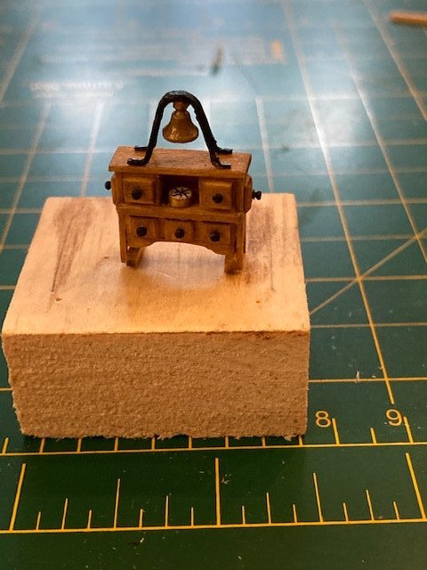
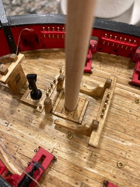
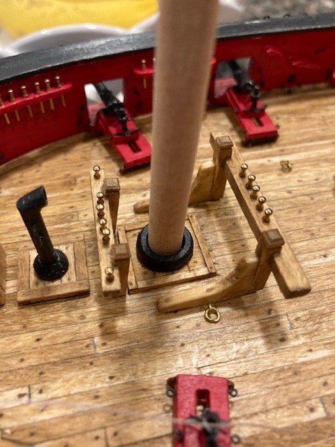
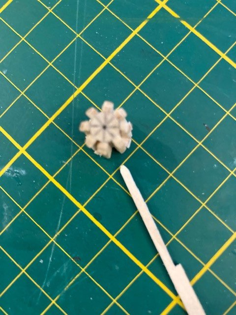
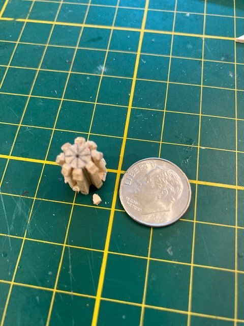
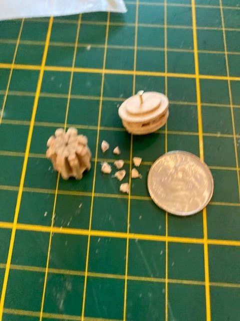
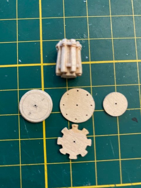
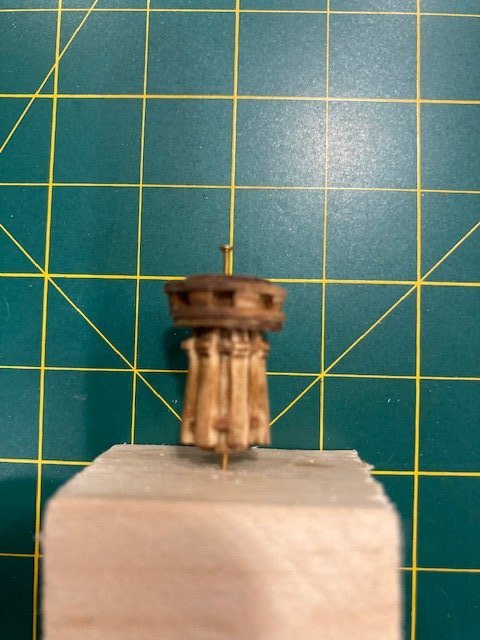
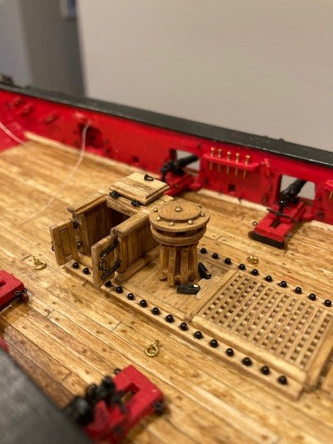
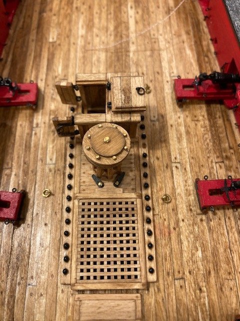
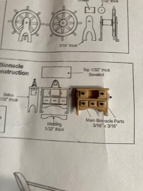
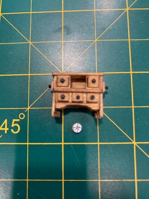
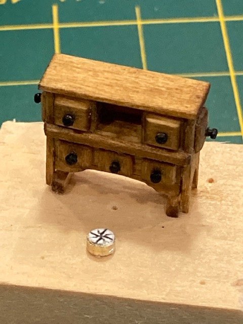
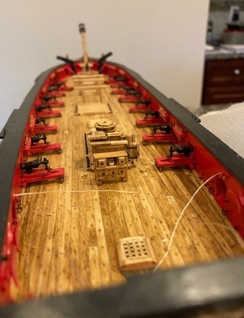
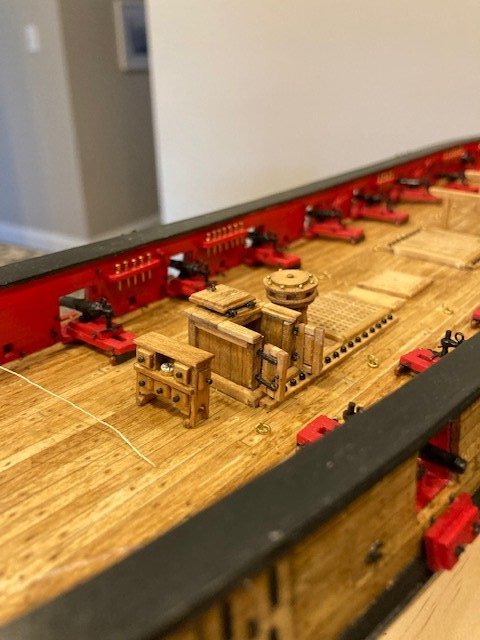
The capstan is complete. I followed the instructions except I used ¼” dowel instead of a 5/32” for the capstan drum. First, I removed the char from the laser cut pieces. The laser cut pieces were cut on a slight angle, so I had to file the edges to even them out. To establish the alignment and spacing of the whelps, I marked out radial lines on the bottom of dowel. Then, I laid the dowel flat and drew horizontal lines along the dowel with a pencil. I ran the pencil across the top of straight edge. The most difficult part was making and gluing the tiny chocks. I bit of a challenge - with challenges come experience, though. The chocks were made from a strip of 1/32” x 1/8” strip that I cut approximately in half lengthwise. I filed the end of the strip to the general shape of the space between the whelps. I inserted the strip into the space between the whelps and marked a line where it will be cut off. I then cut the strip and repeated the process for rest of the chocks. I glued the chocks in-place. After allowing them to dry sufficiently, I filed each one down. I added some rivets to the top of the drum, made from brass pins. I added the pawls – these are not discussed in the instructions. For the pawls, I mimicked Dubz build. The binnacle: Made basically according to the instructions. The back board was probably not that wide back in the 1800’s, so I simulated some board joints by scribing lines across the board with an awl. The kit doesn’t include the door on each side of the binnacle. I made these doors from a 1/32” x 1/8” strip. I used brass nails for the door and drawer knobs. The nail heads were trimmed down using a Dremel and a file. Rather than stain each piece, I stained the complete binnacle. The compass was built out of a piece of 1/8” diameter brass tube and a 1/8” dowel filed down to fit inside the brass tube. I made a copy of a compass image from the internet, scaled it down to slightly smaller than 1/8” diameter, printed it on white paper, carefully cut it out, and glued it on top of the compass. I finished it off with a piece of clear adhesive paper to simulate glass. I need to add the ship bell to the binnacle. Stay tuned.
- 157 replies
-
- 4
-
-
- model shipways
- syren
- (and 1 more)
-
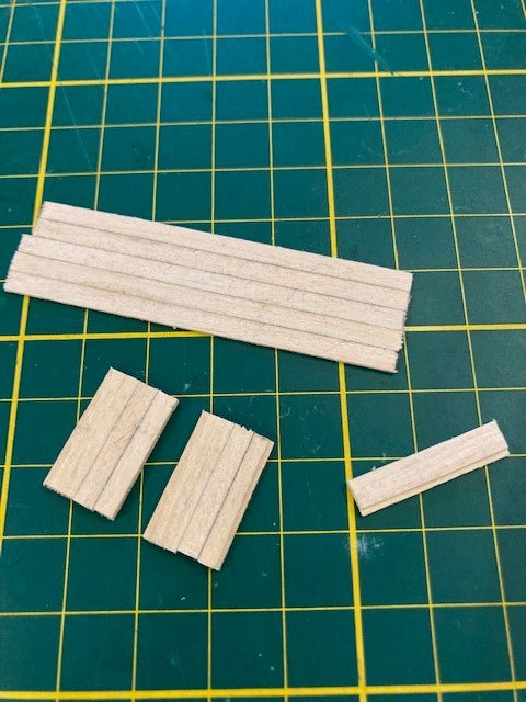
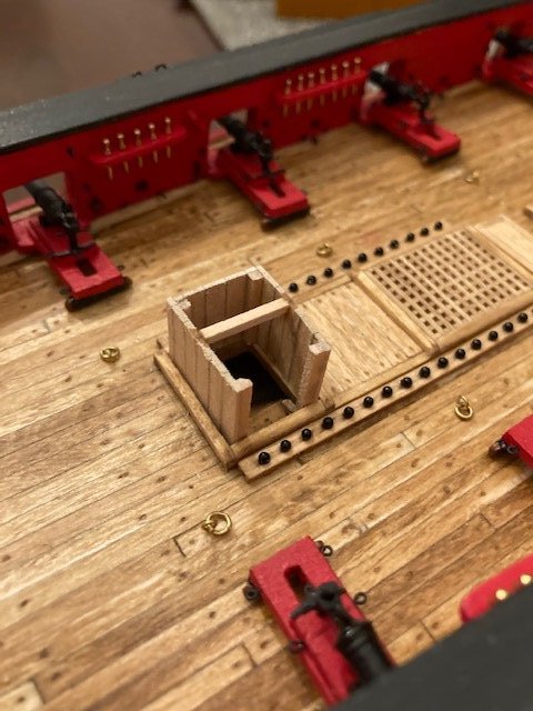
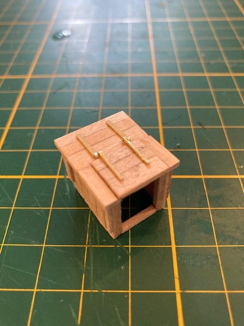
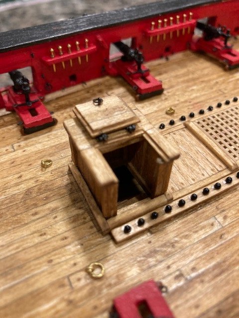
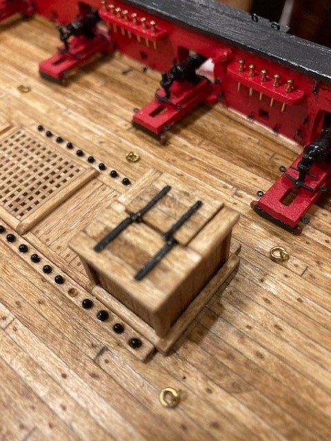
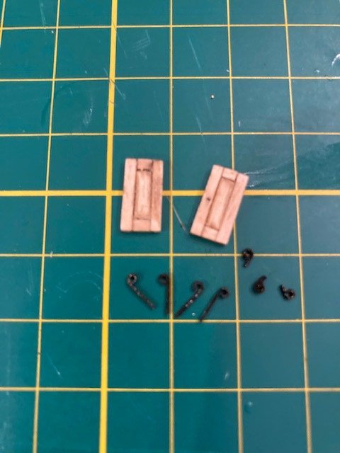
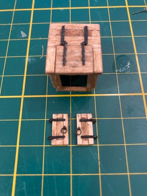
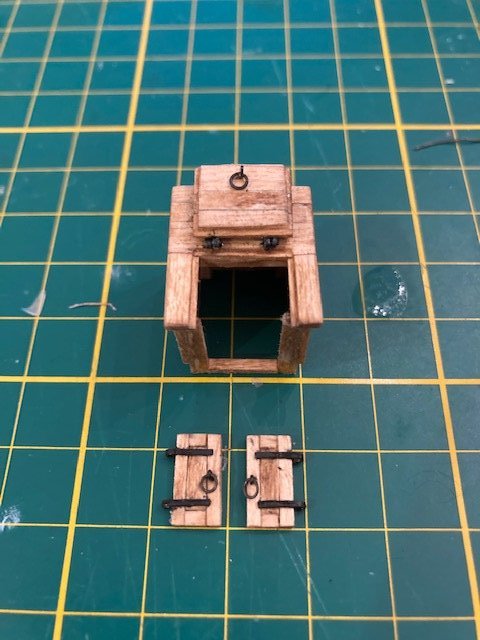
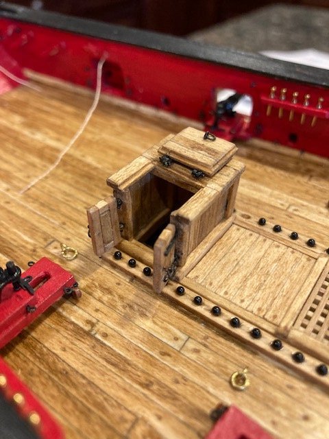
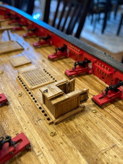
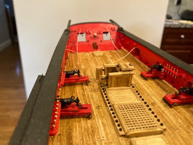
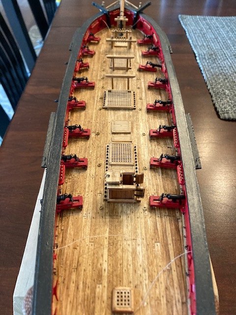
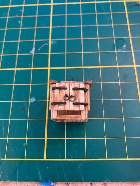
Completed the galley stack. It’s made from the kit supplied 1/8” brass tube cut (with a miter saw) at an angle as per the plan. The two handles were made of 28 gauge black anodized wire. The cut tube pieces were glued together with CA. I marked the location of the handles on the tube based on the plan. The handles were attached to the stack with CA. The process of making the galley stack was surprisingly easy – the most difficult part were the handles. I drilled a hole in the raised platform for the stack to sit and added a chimney foot. I spray painted the stack black. Jumping back to Chapter 12, I worked on the companionway. I looked at several build logs for ideas on constructing the companionway, so the details of the companionway are not totally my creation. For the most part, I followed the instructions but deviated based on what I had seen on the other builds. To begin, I cut five (5), 2 ½” long pieces from one 1/32” x 1/8” strip and glued them edge-to-edge. I ran a pencil along the edge of each strip to emphasize the joints before gluing them. I let the glue dry overnight before cutting the panels. The port side panel had to be trimmed slightly on each side to fit the companion way opening. I added a 1/16” wide strip to the fore and aft panels as per the instructions. I glued a 1/16” square strip at each inside corner. For the top, because I plan to notch the top a la Gahm’s build for the hatch, I used 1/16” x 1/8” strips. I test fit the pieces and, satisfied with the fit, I glued the three panels together. I added 1/16” square strip flush with the top of the fore and aft panels where top panel is hinged as well as a vertical strip at the end of the fore and aft panels where the companionway doors will be attached, and a strip across the bottom of the panels at the doorway. I added some trim boards to the sides. For the top panels, to account for trim boards and the top overhang, I used a 1/16” x 3/16” strip in combination with 1/16” x1/8” strip. I made up two individual panels consisting of two 1/16” x 1/8” strips and one 1/16” x 3/16” strip. The 1/16” x 3/16” strip will be cut down to suit the fit. The top strips run perpendicular to the side panels. I cut the strips a little too short for my liking – would like to have had a little more overhang. So, the moral of story is, if you are going to add trim boards, make the top panels after the trim boards are glued on. Next, I added the wood strips on the top of the companionway on each side of the opening. These were trimmed down from a 1/16” x 3/16” strip and notched for the lid. The lid was filed to fit the opening and notched on three sides. The lid and the companionway were stained Golden Oak. I made a slight miscue – I didn’t allow for the 1/32” x 1/16” planks on each side of the door opening. But I’m not going to deconstruct the companionway to correct this. Once the doors are attached, this won’t be noticeable. I filed the edges of the top panel to even out the overhang and glued the blackened photo etched hinges to the top. I added hinges to the lid as well. I inserted a tiny length of 28 gauge wire through a loop made in each hinge. The lid is functional. I added a lid handle a la the gun port lids. For the doors, I mimicked Gahm’s build. The doors were made from a 1/16” x 1/16” strip with a panel in between made from a 1/16” x 1/8” strip. Attaching the doors was a real challenge. I wasn’t able to find any detailed descriptions and photos from other build logs on how to make the door hinges, so I thought I would provide some detail here. My goal was to make working hinges. It started out well. I the door hinge straps were cut from photo etched scrap. The straps were bent to form a loop. The companion hinge strap that is attached to the companionway is a shorter version of the door hinge strap and is also looped. The straps were blackened. Note: In the photo there's only three short hinges because I lost one - UGH! I glued the door straps onto the door with white glue. Once the glue had dried sufficiently, I placed the doors side by side on a piece of tape and then positioned them on the companionway. Trying to glue the shorter straps to the companionway and to get them to align with the door straps was an exercise in futility. The shorter straps are so small that they are easily lost if dropped or fly off the end of the tweezers. I had to remake several of them. The shorter straps wouldn’t adhere to the stain. After several failed attempts, my frustration got the best of me and I abandoned the working hinge approach. I decided to simply glue the door straps to the companionway as per the instructions. I inserted a brass pin head into the strap loop to simulate the hinge pin. I filed the head of the pins down using a file and my Dremel. While I'm disappointed that the doors don't have working hinges, I'm satisfied with how the entire companionway came out. Now, its on to the capstan. Here are some photos of the completed companionway.
.jpg.e214c7b794c07a9124e7352f73d7ec15.jpg)
- 157 replies
-
- 6
-
-
- model shipways
- syren
- (and 1 more)
-
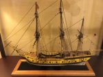
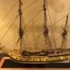
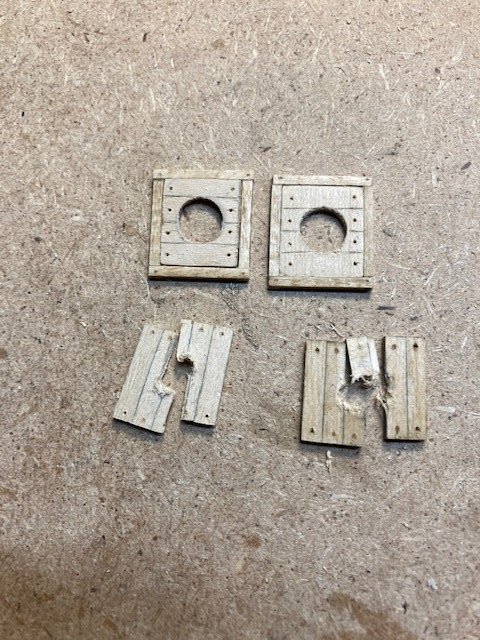
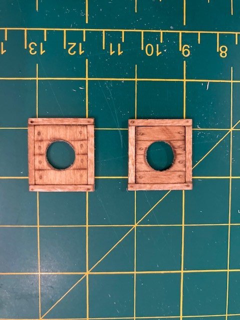
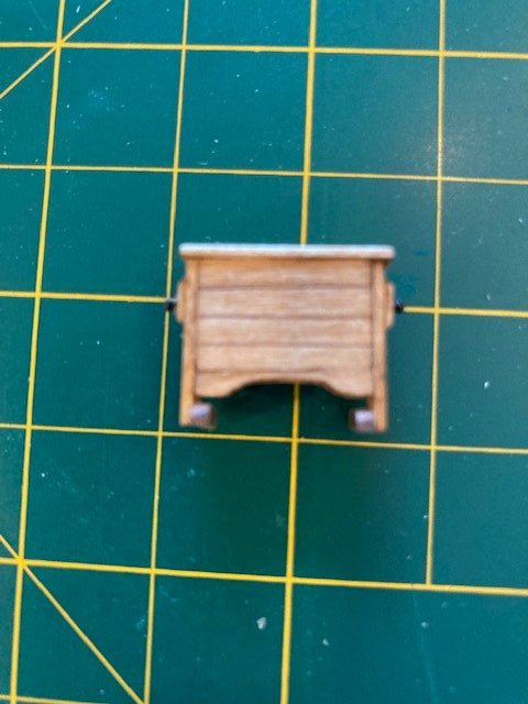
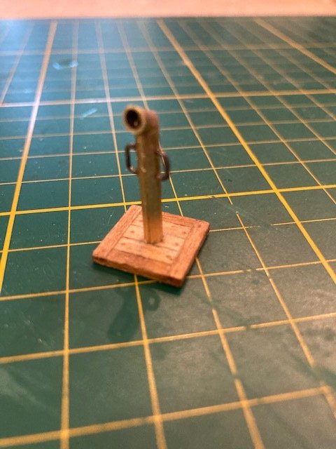
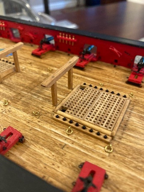
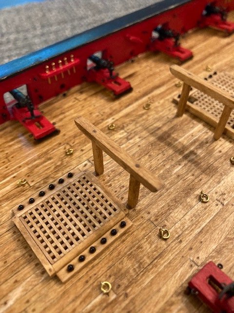
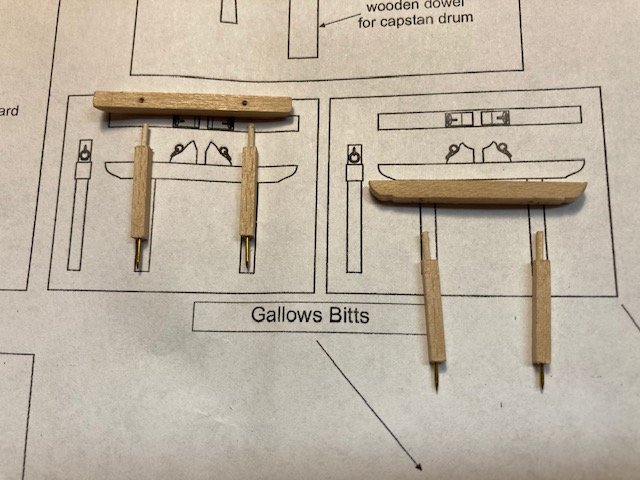
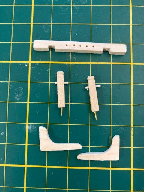
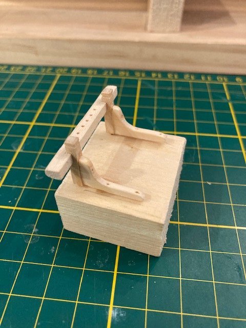
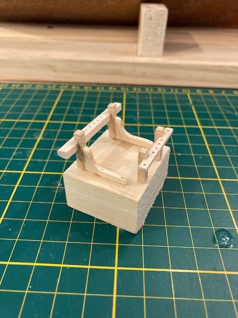
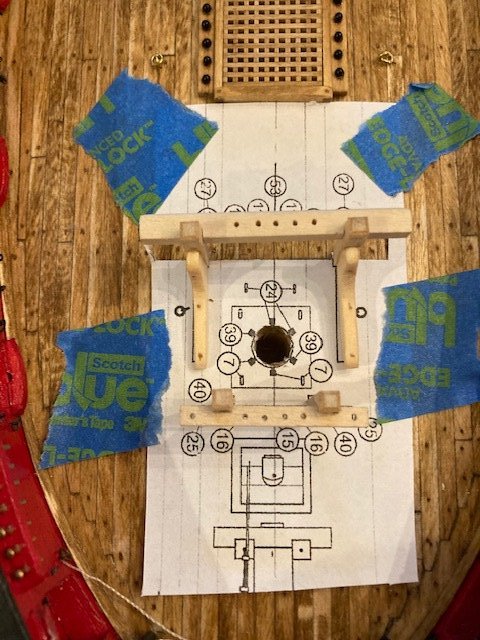
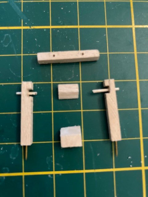
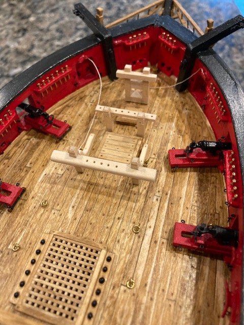
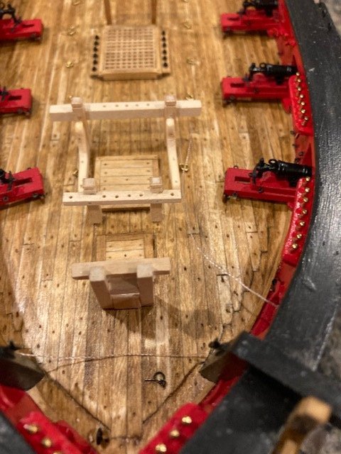
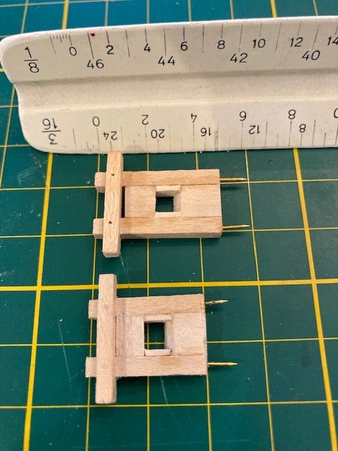
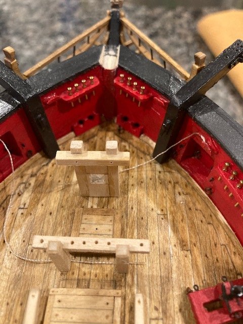
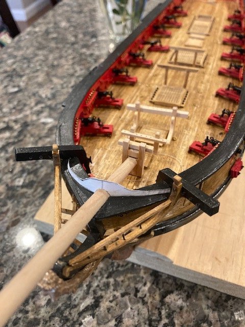
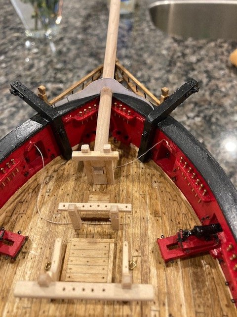
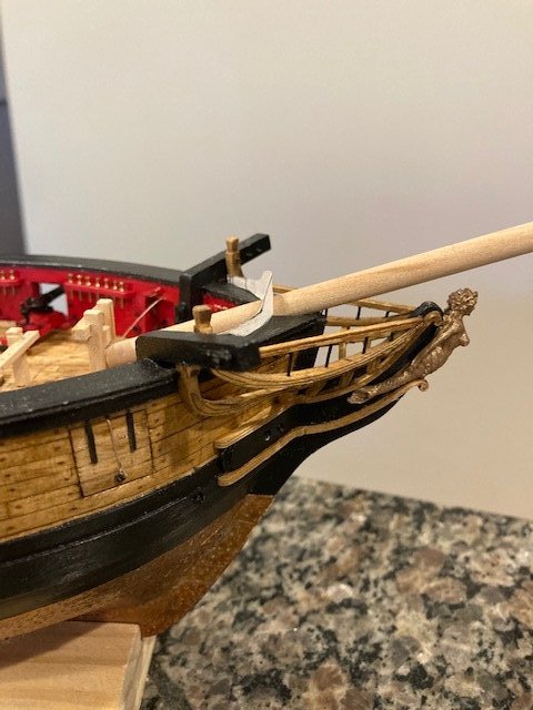
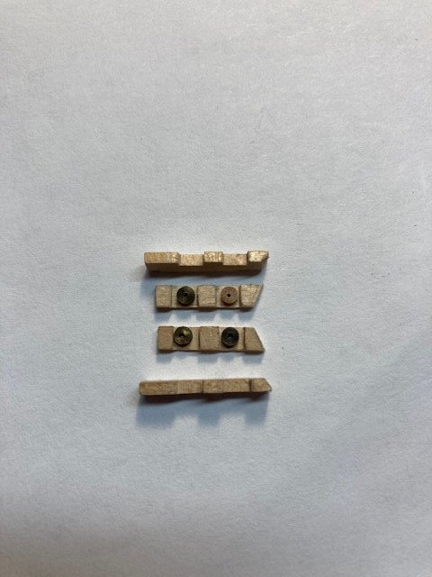
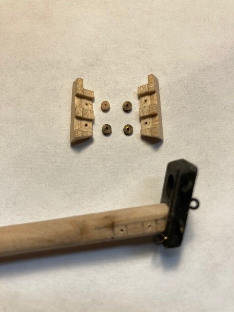
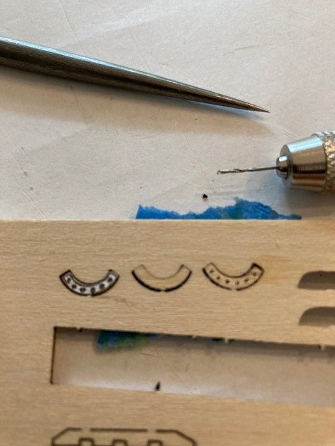
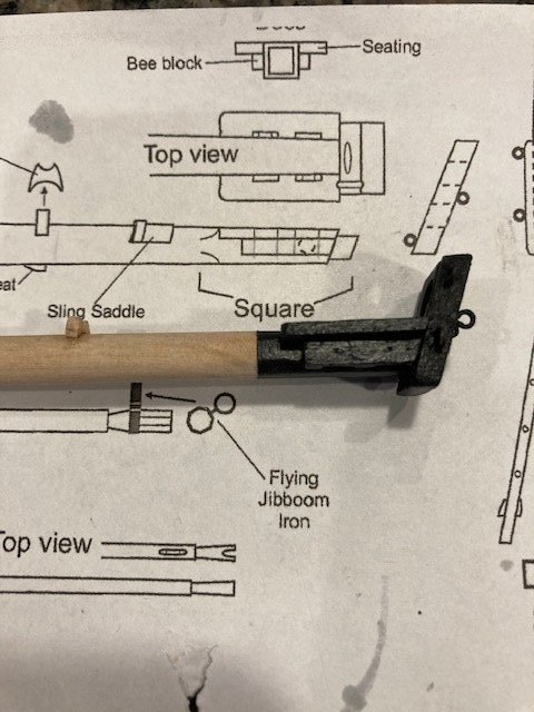
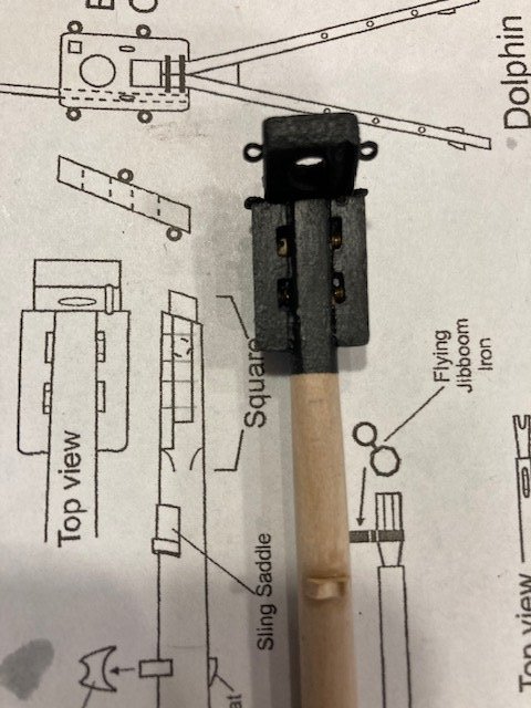
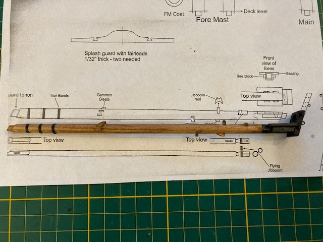
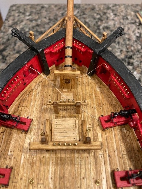
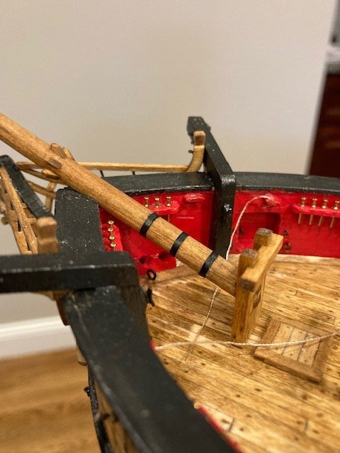
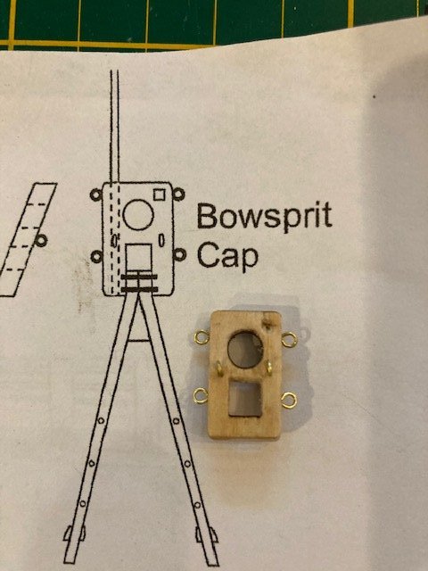
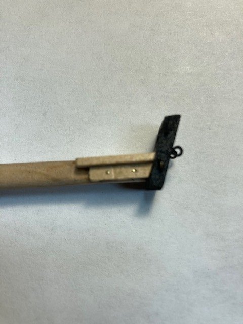
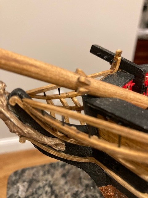
I've made quite a bit of progress in the last two weeks. I made the gallows bitts using 3/32” square strips for the posts and 1/8” square strips for the tops as per the instructions, except that I dowelled the tops to the posts using a toothpick sanded down to about 5 mm. A brass nail was inserted in the bottom of each post to pin the bitts to the deck and provide stability. I find brass nails to be resourceful because once the location of the fitting is determined, you press lightly on it and the pin marks the point where you will drill the hole for the pin. The chocks for the ship’s boat will be made later. The bitts were stained Minwax Golden Oak and temporarily pinned to the deck. The Riding bitts: The heavy beam was made from a 3/16”x 1/8” wood strip. The aft side was rounded off. Instead of notching the posts, I notched the beam -OOPS! (Structurally, the beam was probably stronger with the posts notched out.) To secure the posts to the beam, I inserted a dowel a la the gallows bitts. I cut out the plan view of the beam and used it as a template to mark the location of the notch for each post and the five holes for the belying pins. The notches were made by making a vertical saw cut at each notch line and then making a horizontal knife cut between the saw cuts. The notch was easily removed and squared up with a file. Five holes were drilled along the top of the beam for the belaying pins using a 5 mm bit. The two posts are made from 1/8” x 1/8” stock. To make the decorative post top, I filed a groove around the top of each post with a needle file and then chamfered the edges above the groove with a flat file. The two knees that support the riding bits were a bit of a challenge. IMO, these should have been laser cut. And, there is no 1/16” thick stock provided with the kit to make them. I tried, unsuccessfully, cutting them out 1/16” boxwood. Note: The knees scale more like 3/32” on the plan. I ended up making them from pine. I traced the outline of the knee on 3/8” piece of pine and cut it out with the coping saw. Using a miter saw, I cut two 3/32” strips from the cut block. The shape of the individual knees was then refined by filing and sanding. I pinned the knees to the post to provide some stability when gluing the knees to the posts. Brass pins were added to the bottom of the posts to secure them to the deck. The fore bitts: The posts were made from 1/8” x 1/8” stock instead of 3/32” x 3/32” stock because, not reading ahead in the instructions, I made them at the same time I made the riding bitts posts – its’s not noticeable to the naked eye. The cross beam was made from a 1/16” x 1/8” strip per the instructions. I notched out the cross beam instead of the posts. I cut out the plan view of the cross beam and used it to mark the location of the notch for each post and the six holes for the belying pins. I pinned the posts to the beam with a wood dowel. The posts will be pinned to the deck. To establish the location of the gallows, riding and fore bitts, I cut out the plan and used it as a template. I drilled a hole in the deck at the location of each bitts post and then test fit the bitts. The bitts were stained and temporarily placed on the deck. The bow sprit bitts were made per the manual except for the cross piece. As noted in Sald’s build log, there is a discrepancy in the size of the top. The instructions indicate the cross piece to be 1/16” x 1/16” but detail on Sheet 4 the drawing it scales off as 3/32” x 1/8”. I followed the drawing dimensions and made the bow sprit from some wood stock. I notched the 1/8” square posts and made wood dowels to pin the cross piece to the post. I made the upper and lower packing pieces between the posts from stock material. The packing pieces were made from a 1/32’ x 1/8” wood strip. I decided to start making the bowsprit (Chapter 16). In the meantime, I pinned the bow sprit bitts temporarily to the deck Bowsprit: I made the square for the bees, sanded the ¼” dowel to the approximate dimensions shown on the plan, and made the square tenon. I test fit the bow sprit with the bow sprit bitts. The angle was too step. I notched out some of the material at the bow and filed it with circular file - the bow sprit was still too high. Not wanting to remove too much material, I decided to redo the bow sprit bitts a la Dubz build, making it about 3/16” taller. This lowered the bow sprit angle, but it still looks a little high relative to the top of the figure head. I don’t think the angle being a little off will have any ramifications. However, I was concerned about the fit of the splash guard. To check the fit, I made a template of the splash guard. It looks like the angle of the bow sprit will not interfere with the fit of the splash guard – so I’m satisfied with the angle of the bow sprit. Continuing with the bowsprit, the laser cut bowsprit cap was filed to the angles shown in the instructions and the plans. I drilled holes for the seven eye bolts. Note: I think the 1/32” eye bolts furnished with the kit look too small, so I used 1/16” eye bolts instead. The grove for the jack staff was filed on the starboard side of the cap as per the instructions. The instructions say the jack staff is made from 1/16” dowel - not furnished with the kit. The parts list says to use 5/32” dowels as 1/16”. I’ll deal with this later. Make sure to partially drill a hole on the port side fore of the cap for the flying jib boom tenon. The cap was painted black. I made the seat for the bees from 1/16” x 5/32” boxwood strip. The 1/8” x 1/32” strip indicated in the instructions isn’t wide enough to make the angled cut shown on the plan. The bee blocks were made from 1/8” x 1/16” wood strip, notched to match the seats. I happen to find some 3/16” brass sheaves left over from my Rattlesnake build 47 years ago – these are a perfect fit. Unfortunately, there are only three of them. I made the fourth sheave from 5/32” dowel. I glued the bees seat and block together, squared the notches up with a file, painted them black, and glued them on the bowsprit. The sheaves are pinned to the bowsprit. Back to the Bowsprit: I attached the laser cut jib boom rest - the hardest part was getting the char off. The “very fragile” laser cut fairlead was a challenge. One side of the laser cut is wider than the other. I cut out the fairlead from the plan and glued it onto the wider side of the laser cut piece. I stuck a piece of masking tape on the back side of the laser board to keep the piece in-place. I made a tick mark with my fine point awl at each of the six hole locations. Then, with a 5mm bit, I very slowly drilled each hole completely through the fairlead. A piece broke off at the end hole- the weakest part. I tried another, same result. The third attempt failed too. I ended up successfully making one from a 1/16” x 3/16” strip. I drilled the holes first, rough cut the piece with a knife and saw, filed it to shape, and glued it to the bowsprit. I did some more filing/sanding after the glue dried. The holes don’t quite line up, but this won’t be noticeable once the martingale stays are rigged. I’m satisfied with it. Next, I made the chock cleats from a 1/32” x 1/32” strip. I saw cut the angle. I made two cleats from one saw cut. The cleats are pinned to the bowsprit. Finishing the bowsprit: I made the sprit sail yard sling per the instructions except that I used a laser cut fairlead piece for the sling saddle. I stained the bow sprit Golden Oak. For the iron bands, I used 1/16” wide pinstripe tape that I had left over from my Fair American build – my kit did not come with pinstripe tape. Enjoying the build while delaying the mundane task of rigging the cannons, I think I’ll jump back to Chapter 13 and make the galley stack.
.jpg.07a0f8ce0407b532b5a2c15e8c865324.jpg)
.jpg.77db6dfb3bfbd7e4621b0c902ceae4b8.jpg)
.jpg.67fd40847dfbc5fe0138c562ea564ad0.jpg)
- 157 replies
-
- 3
-
-
- model shipways
- syren
- (and 1 more)