

abelson
-
Posts
424 -
Joined
-
Last visited
Content Type
Profiles
Forums
Gallery
Events
Posts posted by abelson
-
-
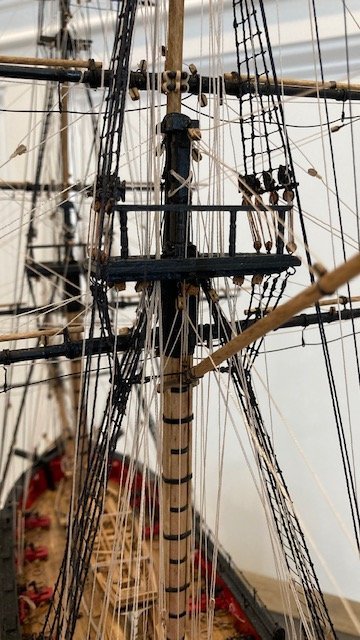
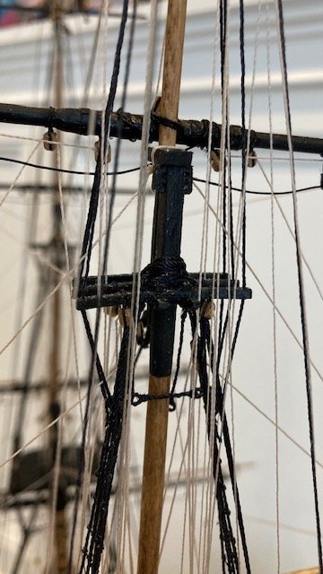
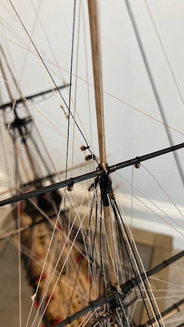
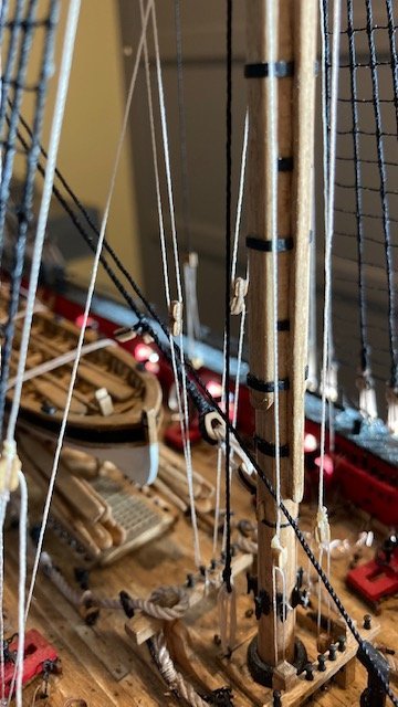
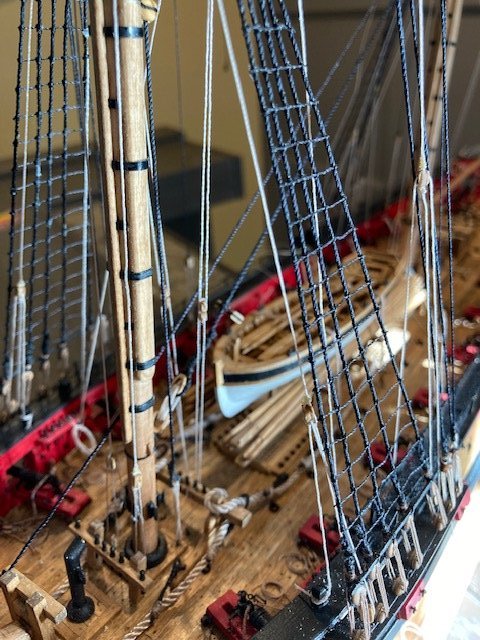
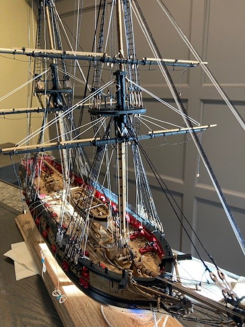
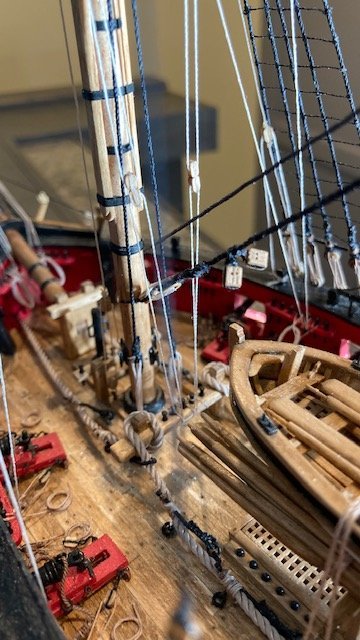
Progress report: With the exception of the main braces, main sheets, main tack, fore sheets, fore tack, and clew lines, I have completed the running rigging. Note: There are a number of 3/32” blocks that have to be added as part of the running rigging as follows: two 3/32” single blocks on the main royal stay for the royal braces, and two pairs of 3/32” single blocks that on the main topgallant stay: one pair for the topgallant braces and one pair for the royal braces. This are shown on Sheet 7 (see photos). I was not aware of these until I read the instructions in Chapter 20. In hindsight, it would have been easier to add these blocks before adding any of the running rigging - a word to the wise.
.jpg.8c427bafdcdb4b0ea33a7757dafdbac2.jpg)
I ran out of .008 tan line and had to order more from Model Shipways. While waiting for the order to arrive, I made the sprit sail yard per the instructions. I used 28 gauge wire for the foot ropes and stirrups. I made the eye bolts from 22 gauge wire.
.jpg.790eea17c20a4a555dce479d3f359ed7.jpg)
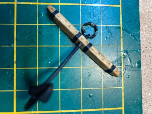
Jumping ahead to Chapter 21, I decided to make the anchor stocks. Rather than make them in two halves, I used a single piece of 1/8” x 3/32” wood strip and tapered it. I drilled a hole at the midpoint of the stock and squared it up with a file. To simulate treenails, I drilled holes in an alternating pattern and filled them with Golden Oak putty. To simulate stock halves, I scribed a line down the center of the stock with a knife. To finish up the stocks, I applied Golden Oak stain. The look of the wood stocks is a huge improvement over the cast metal stocks. I cleaned up the anchor castings and finished them with black acrylic paint. The iron rings were made by wrapping 22 gauge wire around a 1/4” diameter dowel and snipping the ends off. I wrapped rings with sewing thread before attaching them to the anchor. Note: Leave a little bit of the ring ends unwrapped so it fits in the anchor hole.
.jpg.eb43848d62f050ae3d3b30721e63d721.jpg)
.jpg.1e8590a44cd587aac2f520e28d6dc479.jpg)
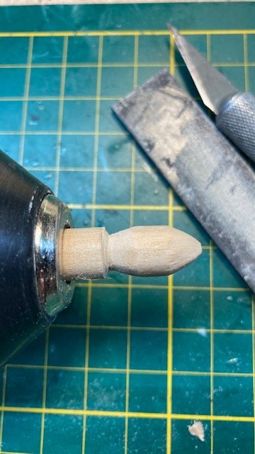
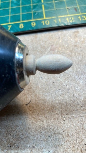
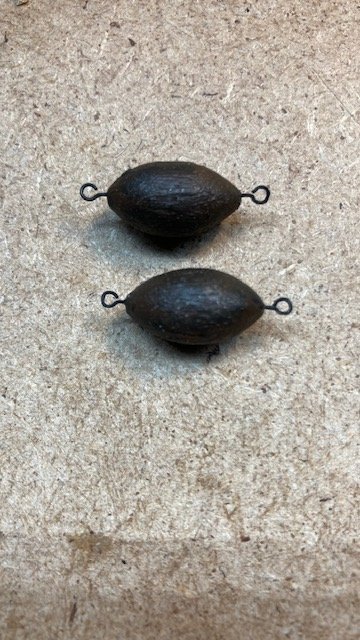
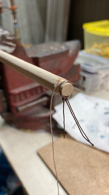
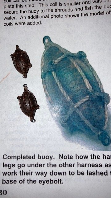
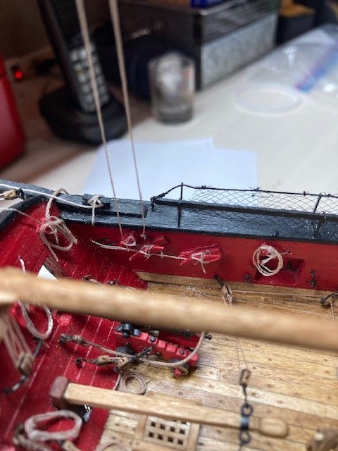
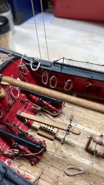
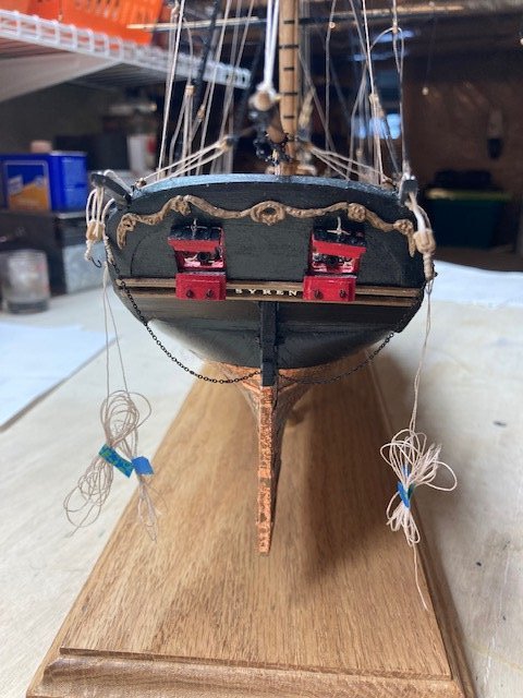
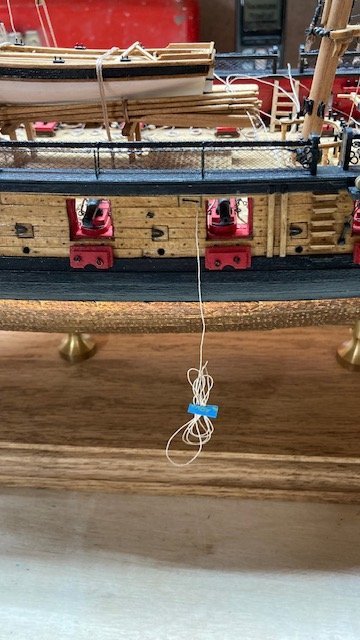
The anchor buoys were next. There are some build logs that have good illustrations and discussions on how to make these - WalrusGuy and SalD for example. I made the anchor buoys from a 3/8” diameter dowel that I had laying around. I carved the general shape first with an x-acto knife and then used my “poor man's lathe” to shape them. The only drawback to this method is that the opposite end of the buoy, i.e., the end attached to the chuck can only be shaped so far until it has to be cut from the chuck piece. It’s difficult to do the final shaping thereafter. I drilled a hole at each end of the buoy for insertion of the eyebolts. The buoys were painted with a mixture of burnt umber and black paint. I started on the anchor buoy harnesses (.018 tan) when my Model Shipways order arrived, so I but them in abeyance to finish up the rigging. With that done, I moved on to completing the buoy harnesses.
For the anchor buoy harnesses I basically followed the instructions. The process wasn’t new to me because I had made the harnesses before for my Fair American build. Nonetheless, it wasn’t easy. I “muddied up” the.018 tan line by lightly painting it with the same mixture of burnt umber and black paint that was used for the buoys. I made up 12 knotted harness lines (about 1.25” long). I knotted each line on a toothpick, applied a little CA, snipped the end of the knot off, and slid the knot from the toothpick. I strung the 3 lines on a length of .018' muddied up tan line. I found it easier to knot the harness before wrapping it around the buoy. To do this, I notched the end of a 3/8” dowel to about 5/8” diameter. I wrapped the harness around the dowel and tied it with a simple overhand knot. I lightly applied CA to the knot, removed it from the dowel, and snipped the loose ends. I draped the harness on the end of the buoy, grasped the 3 harness lines together at the opposite end of the buoy, aligned the harness lines evenly around the buoy, and applied CA to each knot. Next, I seized the three lines around the eyebolt with some tan sewing thread, applied CA, and snipped the excess line. The CA darkened the seizing, so the seizing didn't need to be muddied up.
.jpg.a68f2c839bbbb8829b245b2fdeead5be.jpg)
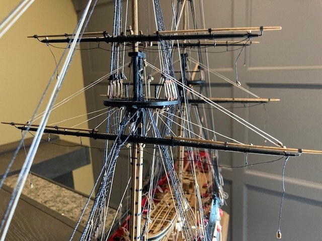
Next, I secured the spritsail yard to the bowsprit with the truss/sling and then rigged the lanyard between the eyebolt on the bottom of the bowsprit cap and the eye (I used an eyebolt here) on the center of the spritsail yard. I had to order more .012 black line to complete the jib guys. In the meantime, I rigged the spritsail lifts (20) and the spritsail braces (21) but did not belay them. They are held in tension temporarily with clips.
.jpg.5c09128d7f992d1a0666efb94ee7adfe.jpg)
.jpg.a81838764a240284a72855d965e4e7a6.jpg)
.jpg.8a6d03e811d489699a64184c81b6dc2b.jpg)
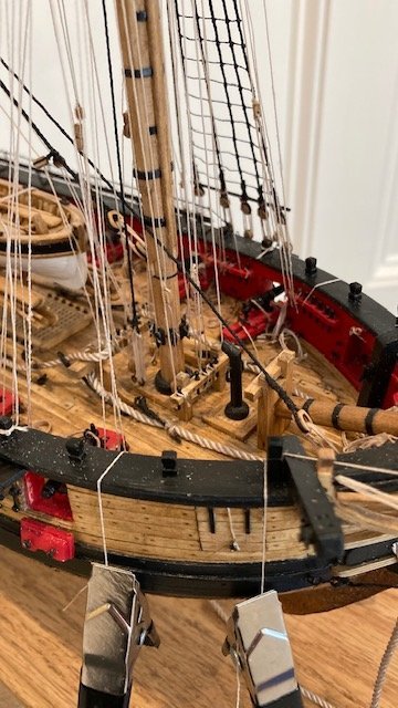
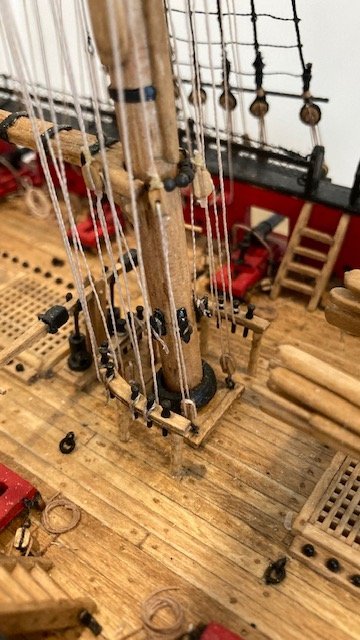
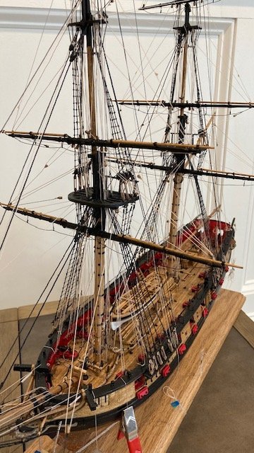
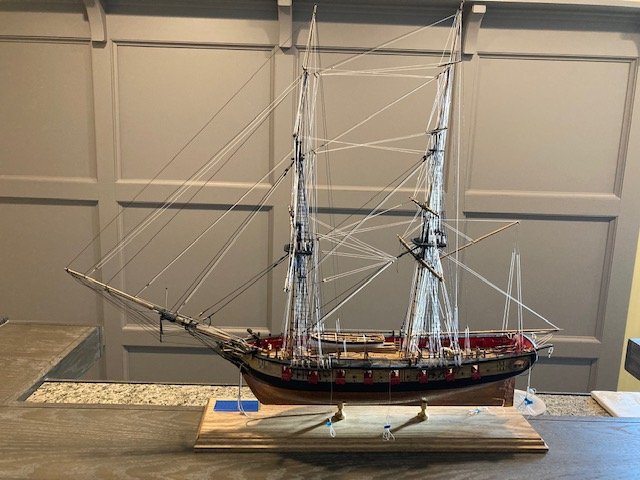
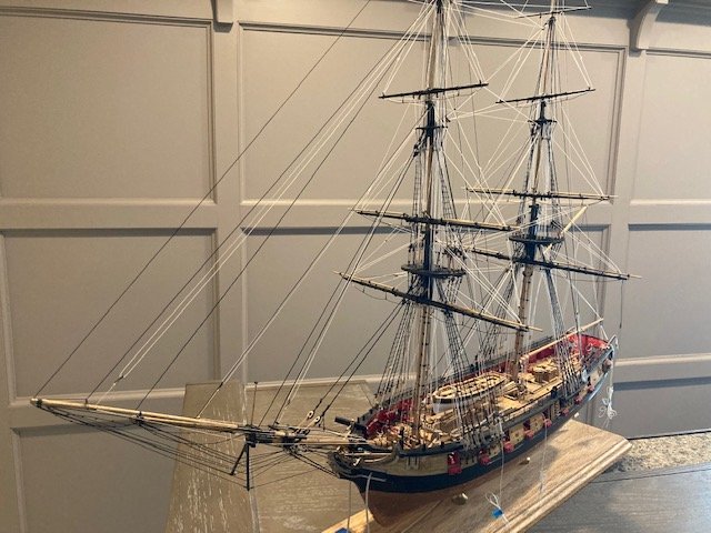
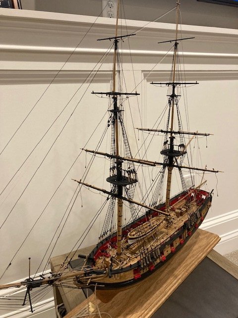
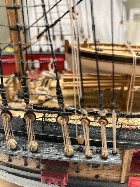
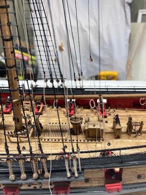
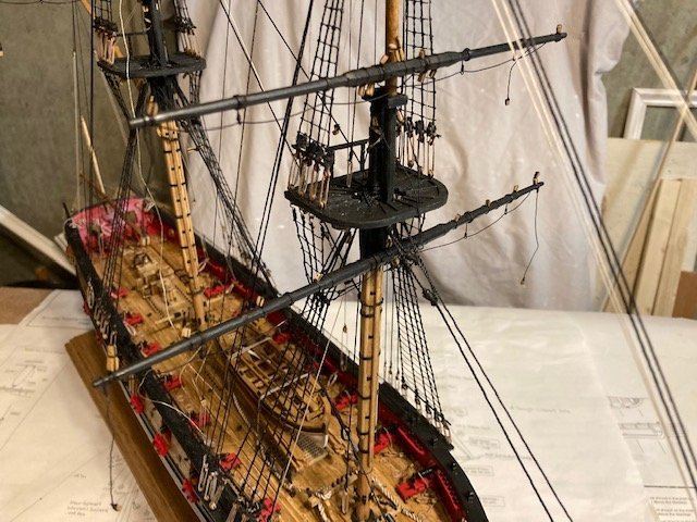
Here are some progress photos.
-
-
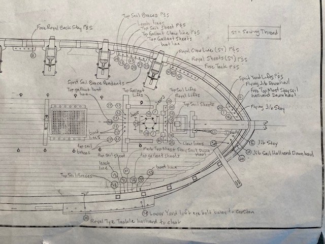
Moving on to Chapter 20, while studying the Belaying Plan, I decided to label the various running rigging lines on the plan as a quick reference for other builders - it’s kind of crudely done (see attached). While doing this, I discovered there are two belying pins on the port side aft most pin rail labelled 51. One of these should be 52. Also, while cross-referencing the plan and the instructions, I discovered on Page 125 that the royal lifts are incorrectly designated to be belayed to 42. This should be 40 (belayed to the fore bits). I think I have everything labelled except for pin number 60. I haven’t yet figured out what gets belayed to pin 60.
.jpg.5621ba68ef849861eb8629c4f970044f.jpg)
I completed the Jeer Ties (.012 tan) for the main and fore course yards. The jeer slings were previously completed (See May 30, 2021 post on Page 4). The jeer ties run in one continuous length through the 1/8” single block on top/center of the lower yard and the 1/8” single block on the end of each jeer sling. The running ends on both sides of jeer blocks are taken down to the base of the mast and set up with a running tackle. I seized a 1/8” single block to both ends of jeer tie and made the 1/8” blocks that are hooked to the eyebolts (designated as number 7 on the Belaying Plan) on the aft side of the main mast and fore mast. The hooks were made from 28 gauge wire. The hardest part (for me) was belaying the line to the mast cleats. I’ll finish them off with rope coils later.
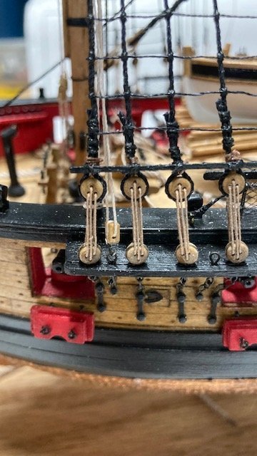
Completed the main and fore lower yard lifts. The trickiest part of the lifts was seizing the .012 tan line behind the blocks lashed to the mast cap. I simply tied a knot, secured it with a little CA, and trimmed the loose end. The tackles (.008 tan) were set up same as the running backstays. The main course lower lift tackle block is hooked to the eyebolt in the channel (designated as number 4 on the Belaying Plan) and belayed pin 4. The fore lower lifts are hooked to the eyebolt in the channel (designated as Number 14) and belayed to the capstan.
.jpg.3037e8fa9fc79a2b284b9dd9940c32ce.jpg)
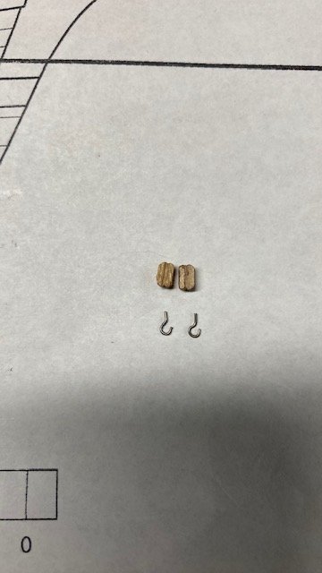
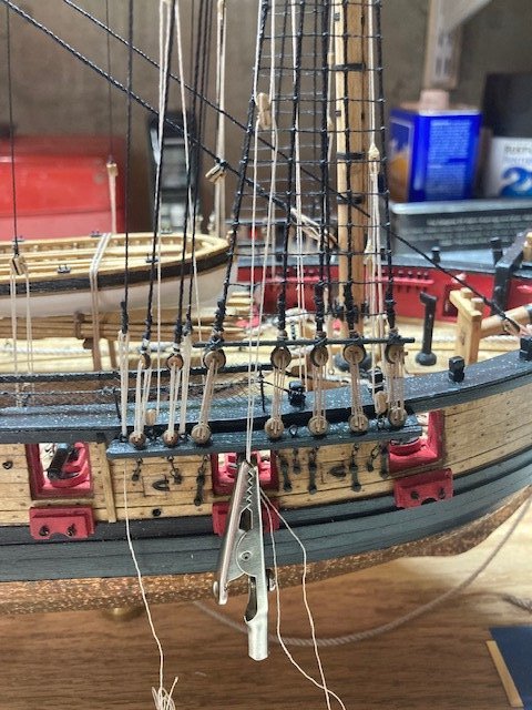
Next up were the fore course leech lines (.008 tan) and bunt lines. These were setup as per the instructions. Reeving the ends of the rigging line through the single blocks hanging under the top was tricky. The fore lower course leech lines were belayed to pin number 13 on the bulwarks rail. The fore lower course buntlines (.008 tan): I created the block assembly using two 3/32” single blocks, stropped together end-to-end. Note: As the instructions advise, make sure you position the sheave holes for the blocks on the inside of the assembly. I ran the rigging line through the various blocks as per the instructions and positioned the double block assemblies about 3” above the deck. To get the height of the double blocks above the deck, I reeved a length of .008 line through the bottom block and attached an alligator clip to the loose ends. I adjusted the line until I got the approximate height above the deck and then lock it in place by applying a little CA to the single block on the yard arm as per the instructions. The falls for the buntlines (.008 tan) were secured to the riding bits adjacent to belaying pin number 11 as per in the instructions. Then, the running end of the fall, which runs through the buntline block, was belayed to the pin number 12 on the bulwarks rail. Next up, the main course yard leech lines and bunt lines.
-
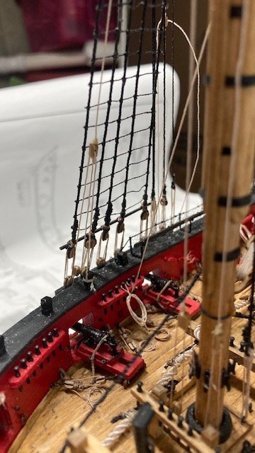
Started on the inboard rigging for the lower course sheets, tacks and braces. Decided to add them as one continuous length, making sure they are long enough to rig later. For the main sheet, I cut a 28” length of .008 line. For the main braces, I cut a 36” length of .012 line. To aid in passing the lines thru the simulated sheaves, I stiffened the end of the line with CA. No problem there. However, belying the lines to the cleats on the bulwark was troublesome and nearly disastrous. I somehow managed to snag the topgallant backstay. The eyebolt came out of the channel. I had to cut the lanyard, re-glue the eyebolt, and remake a new lanyard. Then, the vang eyebolt came out of the bulwark. I was able to simply put it back in place. Then, one the carronade tackle eyebolts came out. I was able to re-glue it. Aside from not being so clumsy, the lesson learned here is to adequately secure the eyebolts from the get-go. Wait, there’s more. I snagged the flag staff (an added feature that is not part of the build) and broke one of the brackets. I was able to repair the broken piece with some white glue followed by a little CA. All and all, disaster averted. Whew. Oh, one more thing, not sure how or when it happened but, the striker broke at one of the pre-drilled holes. Luckily, it didn’t completely break off. CA glue to rescue again. I managed to complete the port side sheets and braces and added rope coils. I'm not sure I like the rope coils. They don't seem to drape naturally, but I think they're okay for the layman's eye. Although this is my third build, I still have trouble belaying lines to cleats in the traditional manner. The problem is, working with an implement in each hand - a necessity for inboard rigging. Also, the work is in close quarters, fraught with the potential for Murphy’s Law. On the bright side, the starboard side sheets and braces were complete without incident. The loose ends of the course sheets, tacks and braces were coiled up and secured with tape.
Completed the fore sheet rigging, port and starboard – need to add rope coils later. Cut a 24” length of .008 tan line. Also, added the main tacks. Took a chance here and cut a 17” length of .008 line. I say chance, because the plan does depict the true location of the 3 block assembly where the sheets, tacks & clew lines come together. After belaying the starboard side tack line to the cleat and securing it, it appears that the main tack might be a little short. If so, I’ll revert to the instructions and simulate a continuous line. I cut the port side longer. Note: I had more success belaying the lines to the cleats. I discovered it’s easier if you do it all in one motion. The tricky part is securing it with glue while holding the line in place. This completes Chapter 19. Now the running rigging starts in earnest with the sprit sail yard to follow.
.jpg.356a3e48bd0e6977bea66eb9c2e7bba2.jpg)
-
14 hours ago, Overworked724 said:
Hey Steve. My deepest condolences on your loss. 🙏🏻 I’ll keep you and your family in our prayers.
I’ve been forced to take a break recently as well. Always looking to your build for ideas and guidance. Your work is inspiring!
👍🏽
Thank you, Patrick.
-
1 hour ago, Gahm said:
I am really sorry to hear about your wife's passing! My deepest condolences!
Thomas
Thank you, Thomas.
-
To: Justin P., Dave E., Ryland Craze and WalrusGuy
Thanks so much for the condolences and the compliments. Working on the ship does take my mind off things. There's some solace in it.
- Justin P., Dave_E, Overworked724 and 1 other
-
 4
4
-
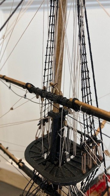
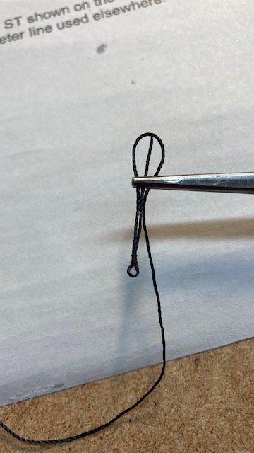
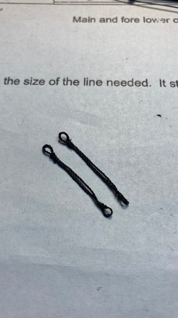
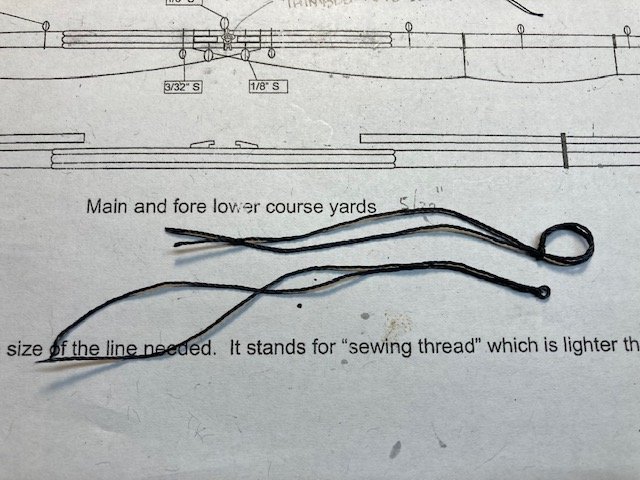
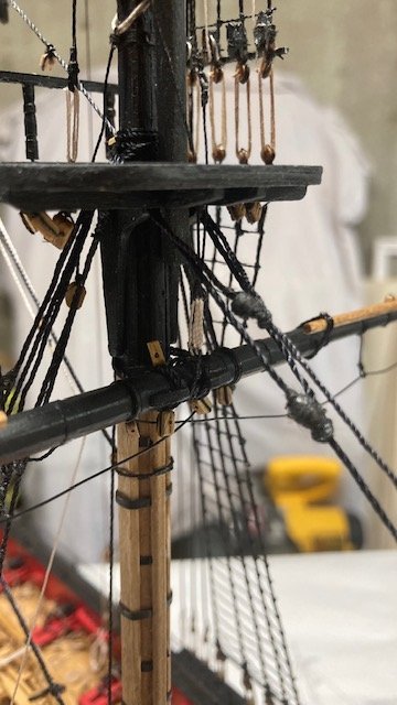
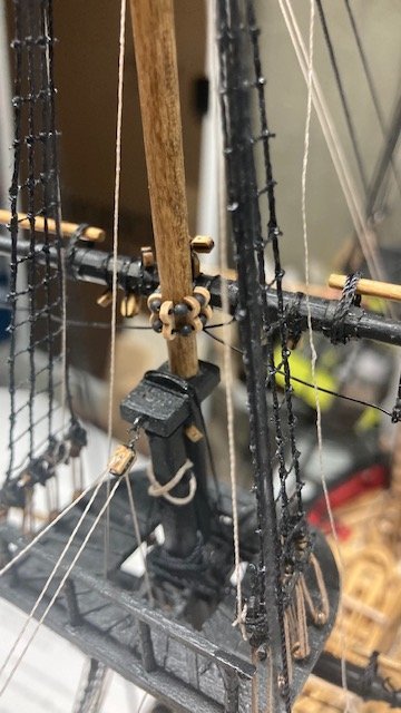
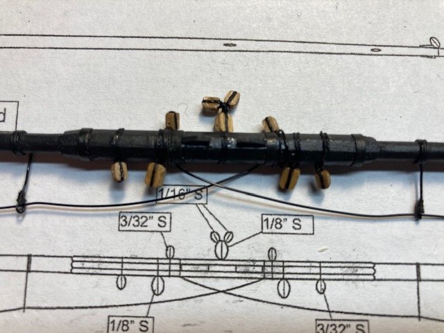
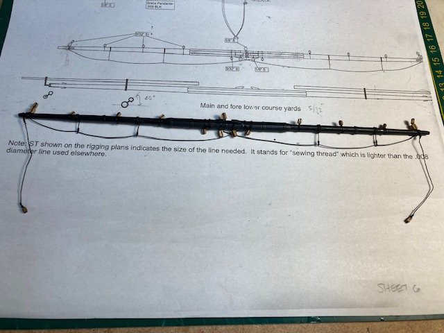
Took some unanticipated time away from ship building due to the expected/unexcepted passing of my wife of 49 years – she lost a courageous 4-year battle with small cell lung cancer. Managed to complete the main and fore lower course yards. Added the simulated sling and thimble that is lashed around the yard at its center between the sling cleats. The thimble should be positioned on the front of the yard as depicted on Sheet 6. Whence the yard is pinned to the mast, the simulated thimble will be lashed to the thimble on the end of the sling with a lanyard. The instructions are vague as to how to make the thimble so I thought I would describe how I made the sling and thimble.
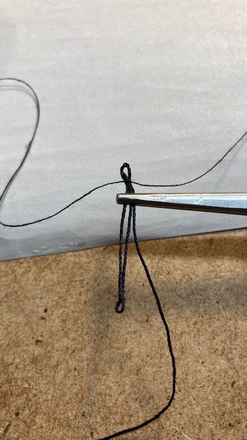
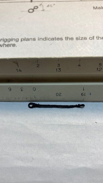
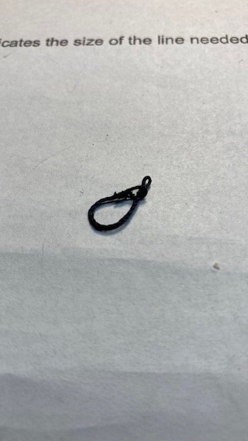
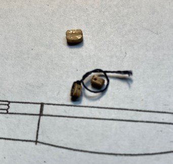
The sling was made using .021 black line. I looped one end and seized it with sewing thread. I added a little CA to stiffen it. I created a loop at the other large enough to pass the eye through. When you loop the line you’ll have 3 ends. Seize all 3 together and then snip off 2 of the ends. I always apply a little CA to the ends to be trimmed to make them easier to clip off. I didn’t stiffen the opposite end loop. The slings are about 1” long from loop to loop. The following photos may be more illustrative of the process.
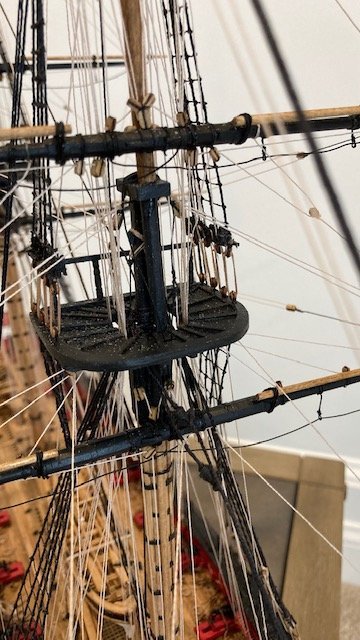
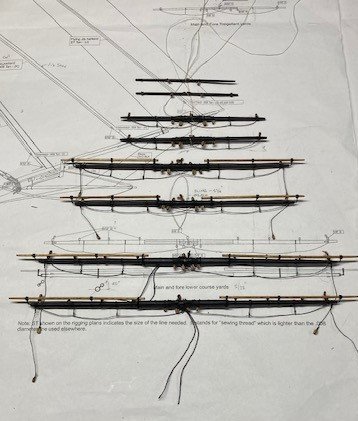
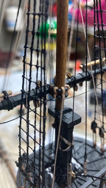
This is also a good time to add the simplified truss. Note: Chapter 19 says “use a generous length of .018 black rigging line for the truss.” Chapter 20 says the truss is .021 black line. I used .021 black line. The truss was made and attached to the lower yard as per the instructions in Chapter 20. I attached the stuns'l booms and irons. Lashed the booms to the yards using some .012 black rigging line. The lower yards were pinned to the mast. Tying the truss around the mast was difficult. Rather than seize the two loose ends after wrapping them around the yard, I simply secured them with CA and trimmed the ends.
.jpg.05c3ec35e427470a7e5349ba85dde432.jpg)
.jpg.b06c293dc244d8ba70bfee8c51e6e47d.jpg)
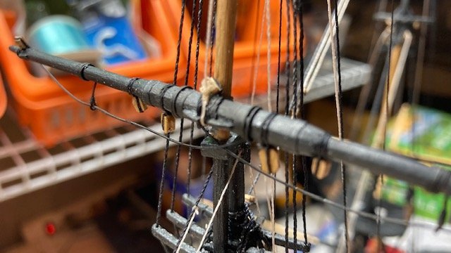
The lanyard (.008 tan) was set up between the thimble and the other simulated thimble on the end of the sling. Lesson learned: I made the sling to the configuration shown on plan sheet 6. This resulted in a lanyard that was too short for my liking, so I shortened the sling. If you want a longer lanyard, make the slings shorter than depicted on the plan.
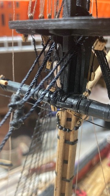
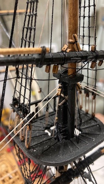
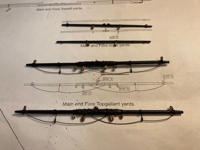
With the lower course yards secured, I moved on the top sail yards. The stuns’l booms and irons were attached to the yards a la the lower yards. The parrels for the top sail yards were made with the small wooden ribs and round trucks supplied with the kit. I sanded the char off the ribs and strung the ribs (5) and the trucks with .018 black line. The illustration is provided on the plans isn’t clear as to how to do this. I simply strung the ribs and trucks on one line and created a loop on one that went around the yard. The yards were pinned to the mast and the two loose ends of the parrel were wrapped around the yard and tied off. The line was secured with a little CA and the loose ends were trimmed.
The topgallant and royal yards were attached to the mast with a simplified trust (not pinned) same as the lower yards. The topgallant yard truss was made with .021 black line. The royal yard truss was made with .018 black line. The topgallant and royal yard tyes were passed through the simulated sheave in the mast.
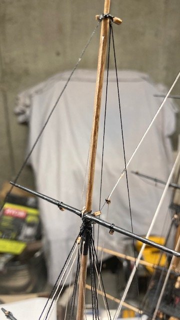
I decided to create the running tackle on the end of the tyes but to not belay the running end of the halliard yet. They were made from 3/32” single blocks and .008 tan halliard. The note on Sheet 6 says to make the space between blocks double the space of the lower lifts. The space between blocks of lower lifts scales about 9.5”. So, I made the space between tye blocks 19”. In hindsight, I should have reviewed this in greater detail before I cut the length of line for the tyes. Sorry the photos aren't clearer. Next up, the Inboard rigging for the lower course sheets, tacks and braces.
.jpg.4b9543e58086af5fed7f9b9cdac5d895.jpg)
-
-
I admire your courage in creating the letters for the ship name. You've done a good job. In looking at the latest version, my eye is drawn to the letter A. It appears to be slightly smaller. Maybe it's an optical illusion. It could just be the spacing between the letters A and C. I think the letters C and Y could be a little closer too. Just my thoughts. Keep up the good work.
- michael mott, WalrusGuy and Cathead
-
3
-
-
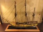
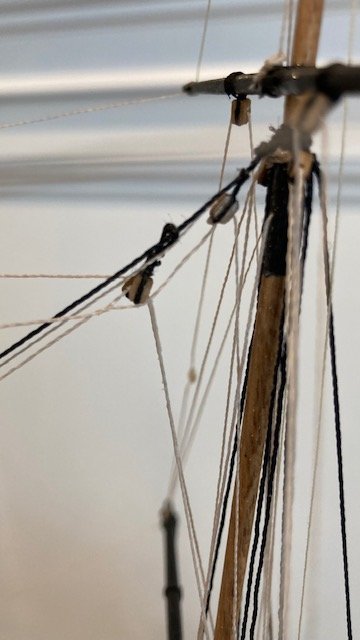
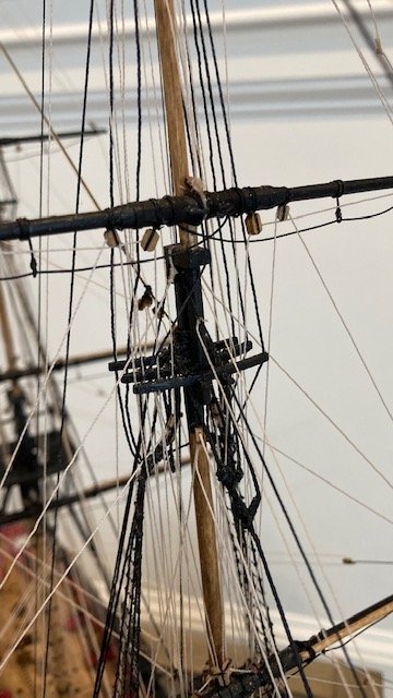
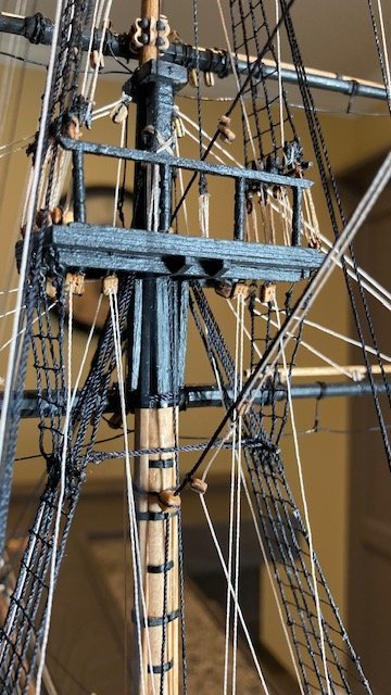
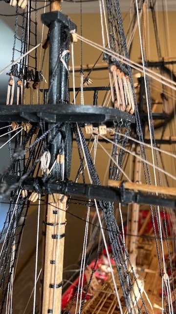
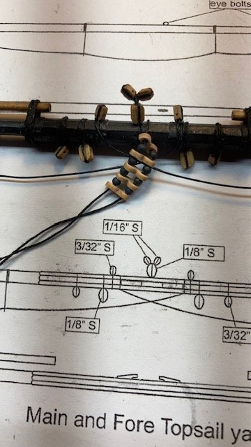
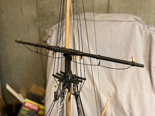
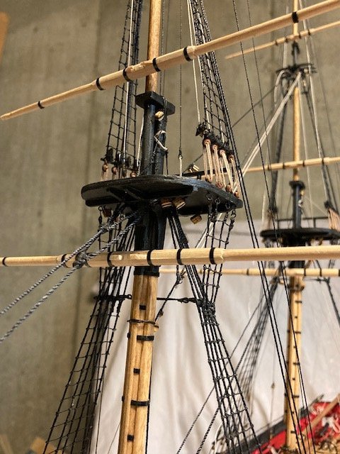
A short progress update. Finished rigging the fore and main top sail yards much the same as the topgallant yards, except for the “micky mouse ears” blocks stropped to the 1/8” single jeer block at the center/top of the yard. These are little tricky. I hadn’t found any discussion on how to rig these, so I decide to post the procedure that I used. First, the plans call for 1/16” single blocks but the instructions on Page 117 for the top sail buntlines call for 3/32” single blocks. The kit is not furnished with 1/16” single blocks, so I used 3/32” blocks. I wrapped a short length of .012 black line around the first block and tied a simple knot. I then cut off one loose end of the line, wrapped the other end around the second block and then knotted and trimmed it. Next, I cut another length of .012 black line long enough to wrap around the jeer block and the mast. I tied the line to the line between the two buntline blocks, wrapped it around the jeer block and knotted it. The completed assembly was lashed to the mast. The following photos show the sequence. The yard brace pendants were also added using .012 black line.
.jpg.5d6eb2baa5161bbc52ef67fec49e956b.jpg)
.jpg.2cf56511e4ef4af584163eca44718aee.jpg)
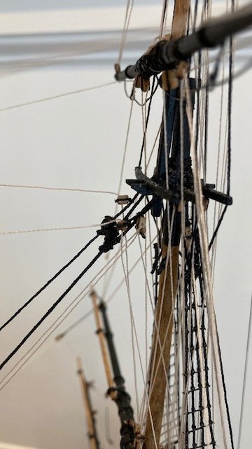
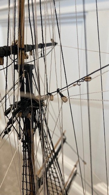
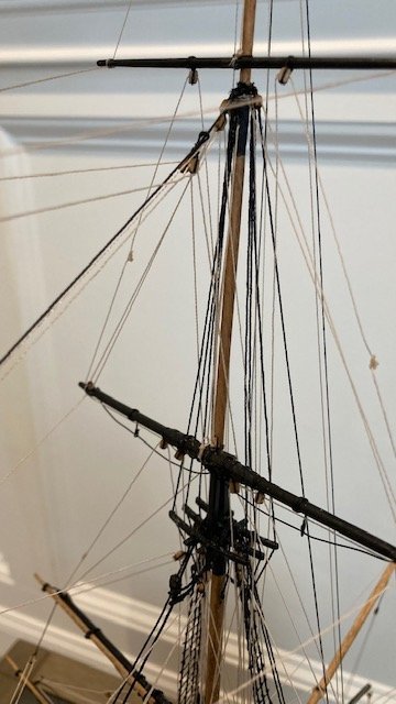
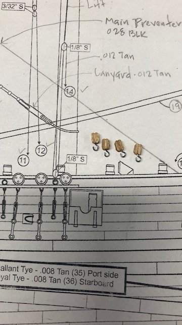
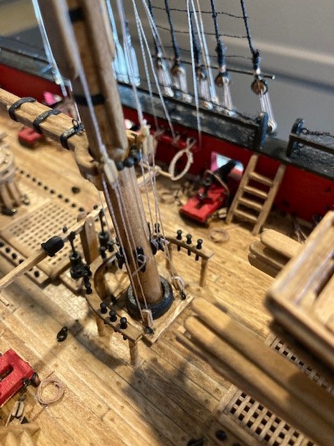
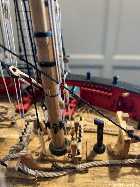
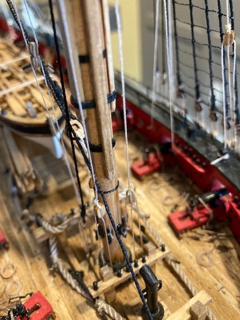
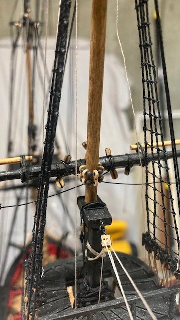
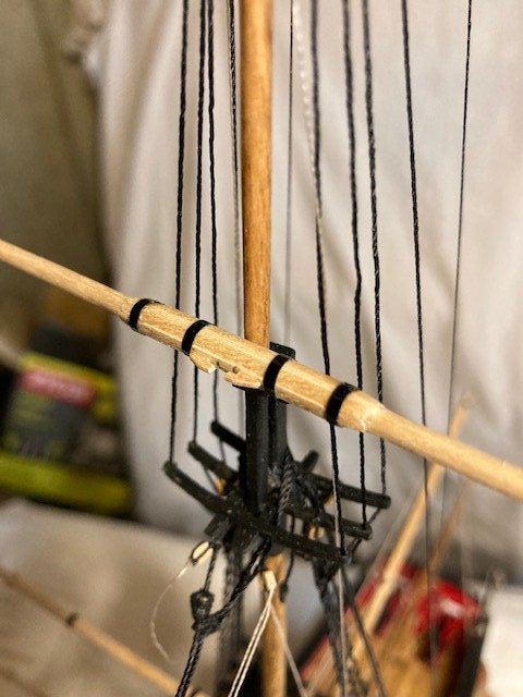
While reviewing Desalgu’s build log it reminded me to add the “tye” to the royal and topgallant yards before permanently attaching the yards to the masts. These are shown but not labeled on Sheet 6. They are shown and labeled on Sheet 7. The royal tyes are made with .008 tan line. The topgallant tyes are .012 tan. I measured the length of the tyes on Sheet 7. I cut a 25” length of .008 line for each royal tye and a 22” length of .012 line for each topgallant tye. I allowed for making the eye on the end it the tye at the mast and setting up the tackle at the opposite end. . The fore topgallant tye is set up on the port side and the main topgallant tye is set up on the starboard side. The fore royal tye is set up on the starboard side and the main royal tye is set up on the port side (see notes on Sheet 7).
.jpg.96d01cc301e132d8916838676708feff.jpg)
.jpg.bf75e7a6750928cc6a1e545abb7f47ea.jpg)
Moving on to completing the lower yards. Stay tuned for update.
-
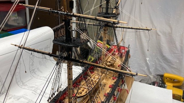
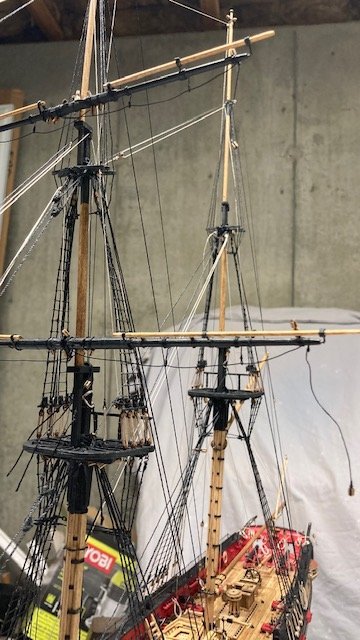
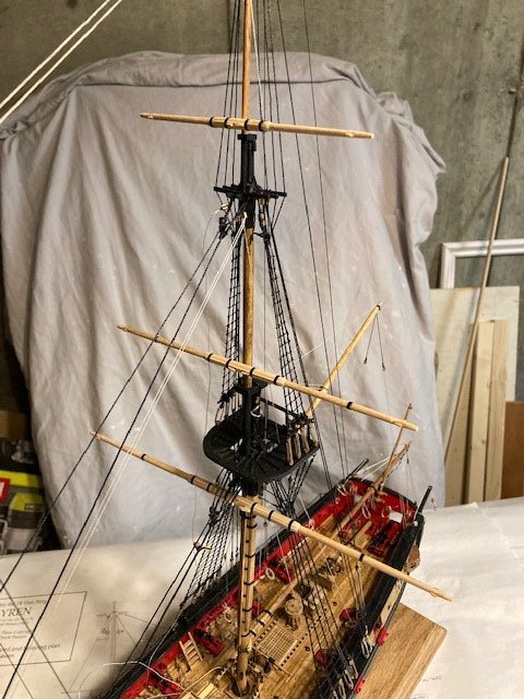
Just a short post. Finished rigging the main and fore lower yards and the topgallant and royal yards. I used 28 gauge wire for footropes. I found it easier to add the blocks before the foot ropes. Added the brace pendants too. Temporarily pinned the yards for effect. Here are some photos.
.jpg.dfcc244c0d3bfb862fdbc26f2569cbd0.jpg)
- WalrusGuy, Gahm and USNCHief013107
-
3
-
On 1/17/2022 at 10:34 AM, Overworked724 said:
Beautiful work, Abe.
Thanks.
-
-
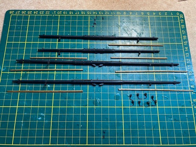
First post of the new year, and now 21 months into the build. Began constructing the lower yard arms (5/32” dowels) basically following the instructions and using the plan. To taper the dowels, I used a poor man's lathe made from two hand drills (see photo). I cut the dowels long enough to insert the ends into the drill chuck. The end the dowel that was being tapered was secured in the drill chuck. The opposite end was allowed to rotate freely in the chuck of the other drill. I used 1/16” strips to create the octagon shape. The strips were beveled. The gaps between strips (minor) were filled with wood filler and then sanded smooth. The sling cleats were made from 1/16" strips. I made a notch in the bottom of the strip and then cut two pieces to size and glued them to the yard. The yard arm cleats were made using a 1/32” strip. I applied a little CA to secure the cleats before shaping them. I copied WalrusGuy’s build log and installed simulated iron bands around the spar battens – it’s a nice supplemental detail. I also added the inner boom iron, positioned about 1/3 the distance from the end of the yard arm. I used 1/16” pinstripe tape for the bands and the inner boom iron. Applied a little CA to secure the cut ends of the tape. I drilled a hole in backside of each yard arm and pinned them, temporarily, to the masts. As much as I liked the natural look of the yards, I decided to paint them black, as most builders have done. The downside of painting them black is that the detailing is not as visible.
.jpg.35c975818c07ef230ae590fb363558b1.jpg)
.jpg.118172a9151839e61a81f46adec46107.jpg)
.jpg.ac920d45196bcc15bdd6abc9b6e4fc39.jpg)
.jpg.1a76751bd75f61b949581908c574d66e.jpg)
I continued making the yards. The topsail yards and topgallant yards were constructed using a 1/8” diameter dowels. Don’t forget the simulated sheaves. The royal yards are made using a 3/32” diameter dowel. Like the lower yard arms, the topsail, top gallant, and royal yards were painted black.
.jpg.1c1c6c98dfdf7d9b79e6f82b04c4c98d.jpg)
.jpg.98f0d15b2e47149a98fa1e49a25338a1.jpg)
.jpg.f5e0e90f4ad52cc5bca6c6673c1517a8.jpg)
.jpg.63767971c4d9745bd4cfec04642d0e25.jpg)
The stuns’l booms were next. I made them from a 5/64” diameter dowel. I didn’t have enough dowel to make all of the stuns’l booms (I was one short) so I had to order more from Model Expo - on back order. I stained the booms with Golden Oak. Note, l didn’t bother to give the inboard ends of the booms an octagonal shape.
Following Chuck’s instructions, the stuns’l boom irons were easier to make than I anticipated. To simulate the hinges on the boom irons I used 22 gauge wire as per the instructions. Rather than to cut and glue tiny lengths of wire, I laid the wire on the boom iron, as if I were going to solder it, and applied CA with a toothpick to adhere the wire to the brass iron. After letting the CA set for a short time, I snipped the wire at the edge of the iron with a nail clipper and filed the ends smooth. I painted the completed boom irons black with Model Color acrylic-colors paint purchased at Hobbie Lobby. This is big step completed. Next, I drilled holes at a 45 degree angle in the pinstripe tape used for the inner boom irons. Before drilling, I pierced the tape with a sewing needle to prevent the tape from getting torn up. I inserted the inner boom irons into the drilled holes and then painted them while on the yard arm - an easy way to paint them. I test fit the boom irons on the lower yards (see photos).
.jpg.f0fd7975139178f54d9cdaf9c12b4741.jpg)
.jpg.7b4dfd0aaf045a62e4e2dee8beefc0cf.jpg)
.jpg.89db9eb8d52b4c892fa50274a1cba4f3.jpg)
.jpg.7b25941cb3d337e6309c56de53176325.jpg)
.jpg.cf3391d6a77ad45c72877ef434536c59.jpg)
The yard arm footrope stirrups were made with 28 gauge wire, wrapped 3-times around the yard, and with the stirrup hanging from the backside of the yard. CA was applied to secure the stirrups. An eye was formed on the end of the stirrup and some sewing thread was added to simulate seizing above the eye. I completed the stirrups on the lower yards. More to follow. Stay tuned.
.jpg.1053515e1e86e939ee8f10445f584783.jpg)
- WalrusGuy, Gahm, Overworked724 and 2 others
-
5
-
Nice work on the scratch build capstan.
- Overworked724 and WalrusGuy
-
2
-
-
Excellent working rudder.
- Dave_E and Overworked724
-
2
-
-
Excellent work on the coppering. One of the better ones I've seen. I'm enjoying your progress.
-
Oh, you're too kind. I'm glad my posts are worthwhile. Yeah, the closeups do tend to show imperfections. You just need a little more sanding. FYI, I had to grind my pedestals to fit the keel.
-
-
Rudder looks great. I like the beefy look of the ladder. I made my midship boarding ladders thicker too. Used 3/32”x 1/8” basswood strip. And, yes it is difficult to get symmetry. FYI, I found that the carronade tackles interfere with the ladders or vice versa. This is not obvious from the plans. Keep up the good work.


USF Confederacy 1778 by WalrusGuy - Model Shipways - 1:64
in - Kit build logs for subjects built from 1751 - 1800
Posted
Just catching up on your build. As usual, nice crisp and clean work. Excellent job on the sides of the quarter gallery.