


iMustBeCrazy
-
Posts
958 -
Joined
-
Last visited
Content Type
Profiles
Forums
Gallery
Events
Posts posted by iMustBeCrazy
-
-
47 minutes ago, Keith S said:
However, my feeling on the subject is that a safety-valve vent or uptake is more-or-less simp,ply a flue, and would hold no pressure. Therefore the wider the better, as its only function would be to carry the moisture, noise, and heat of a safety-valve release clear of the interior spaces.
Sounds good to me, you wouldn't make a pressure pipe any longer than necessary.
-
This seems to be a good explanation of an azimuth compass and it's use: wikiwand.com/en/Azimuth_compass
- clearway and Keith Black
-
 1
1
-
 1
1
-
12 minutes ago, clearway said:
i have heard they would set the azimuth using a celestial body / geographical feature and keep her true using that bearing.
Yep, that works, or the helmsman lines up something between the third and fourth shroud etc. Me, I used a gps connected to digital maps. Too easy.
- clearway and Keith Black
-
 2
2
-
11 hours ago, Keith Black said:
So, was the compass only checked when the sails were reset to accommodate a change in wind?
Kieth, think of it this way. It was the helmsman's job to sail the course given and to notify the officer on watch if he no longer could, the officer would then call for the sails to be adjusted or for a change in course (which may require the Captains permission).
So the helmsman would use everything he could to maintain a course, the compass, the set of the sails, the wind on his ear, the feel of the wheel, the wake behind him etc.
2 hours ago, clearway said:Don't forget Keith the Azimuth compass on the post came into play when they got towards the pole and normal compasses were as much use as a chocolate fireguard!
Keith, the azimuth compass was not a magical device for use near the poles, it's primary function was for taking bearings for charting and navigation. It may have been more suitable near the poles than the compass in the binnacle but that would depend on it's design, or the binnacle compasses could have been better depending on their design.
One of the problems is that the lines of magnetic flux which are roughly parallel to the earths surface over most of the planet start dipping as you near the poles and the compass needle (or disk) tries to point down to follow them, at the poles the lines of flux are near vertical.
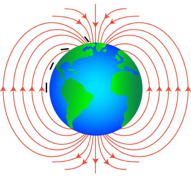
So whether a compass works near the poles in part depends on how far the needle can tilt without falling off or jamming.
2 hours ago, clearway said:Craig i think you could be on the right lines as on the Owen drawings there is no obvious sign of it sticking that far out.
I was thinking more about the safety of you fine model
") I think the plans were probably followed but I could be wrong.
I think the plans were probably followed but I could be wrong.
- Keith Black and clearway
-
1
-
1
-
2 hours ago, clearway said:
Now i have the compass post in place i thought i would try making an impression of the Azimuth steering compass (best i can do in 1/75) measures 4mm square and still need to sort a lid and a stand. Also trial fitted the bridge on the lowered supports.... to carry on my original dilemma before we sorted the compass post i still cant decide whether to go with the full width bridge off the plans or shorten it slightly
As the compass was probably only in place when in use I don't think I'd bother with a lid and I suspect it had something like a hollow box on the base that fitted over the post. Again just guesses.
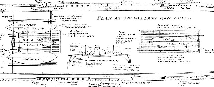
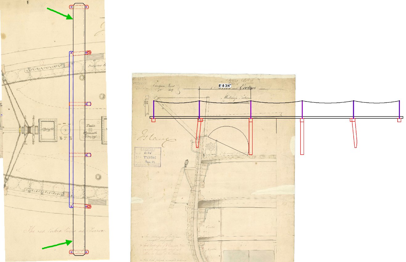
With the bridge, all the drawings show it extending about 8'8" outside the bulwarks (say 35mm) but I might reduce that to 6' (25mm) if I made this model. But I don't think I could work at this scale.
- clearway and Keith Black
-
2
-
1 hour ago, clearway said:
Back to terror and i am thinking that navigation table is too big on the model
It certainly should be narrower than the skylight.
I've re-scaled my drawing and the table is drawn as about* 4'0" x 3'8" which scales down to 0.64" x 0.58" or 16.25mm x 14.9mm with the compass post 6" x 6" ( 0.08" x 0.08" or 2mm x 2mm ).
The bridge is about* 1'11" ( 0.3" or 7.8mm )
Post height from the deck is about* 6'10" ( 4'9" above the table ) scaled 1.10" or 27.8mm
* variations in line thickness, hand made rulers, paper distortion etc.
- clearway and Keith Black
-
2
-
2 hours ago, clearway said:
Cutty Sarks compasses in the link about compasses from Keith B how her Azimuth compass was also between the skid beams.
Oops, you distracted me. I didn't really find anything:
I did find a later photo showing the deckhouse roof between the boats but by then it was fitted with a winch and a bloody great (I think iron) water tank.
- Keith Black and clearway
-
2
-
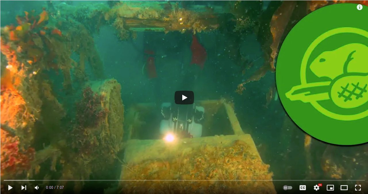
What a pity this scene doesn't appear in the Parks Canada video :(
In the Terror site sketch ( post #509 ) we see both skylights have a section of their roof missing, possibly blown out by air pressure as she sank.
- DanielD, Keith Black, clearway and 1 other
-
4
-
20 minutes ago, Keith S said:
Well, I will tell you what I was thinking of doing. Right in front of the wheel, there's the flat-topped skylight over the Captain's cabin. I was toying with the idea that a binnacle (the old-fashioned "box with a lamp in it" kind) may have been lashed to the top of it.
In the paragraph that Keith Black showed us, Dr. Betts reveals that there may have been a binnacle on either side of the helm. Also in John Ross' account of his voyage on the Alexander he writes about a binnacle on either side of the helm.
This seems like good intel, but I am wondering, what did a "binnacle" look like in 1845?
Are you trying to steal my thunder? You're not supposed to agree with me straight off the bat. I wanted arguments as to why I was wrong.
What did they look like? I'm guessing fairly simple as they were removable.
Some choices: https://www.rmg.co.uk/collections/objects/search/binnacle?images=yes&date_from=1800&date_to=1848
_Erebus_(1826)_RMG_J1409c2.png.38bc82c405b2ab6089a6cbf67ceadfe5.png)
-
36 minutes ago, Keith S said:
You've solved another one of our big mysteries!
Thanks Keith, I'm sure it's right but it's easy to be sure about your own ideas, even when they're wrong
")
On to the binnacles, this is harder as there appears to be no hard evidence. So, one question at a time.
Why wouldn't the binnacles be if front of the helmsman where they belong? Can anybody suggest a reason this is not possible? (that's one question rephrased) Answers must include a stamped self addressed envelope.
- Keith Black and clearway
-
2
-
38 minutes ago, clearway said:
This ship is going to drive Keith S and myself completely nuts
Why do you think I chose my username?
The following is not intended to be condescending in any way, it's just me trying to put into words what I see.
My logic.
First, the azimuth compass is used to take bearings of objects (hills for example), you need to get your eye right up against the sights (somebody used the right word above but I can't find it) so the compass should be at about eye level. You also need to be able to take bearings in any direction, even behind you. That rules out taking bearings from the bridge.
Now lets look at the drawings:
The height of the' table' is about two foot three inches, so to take bearings using a compass on the 'table' would mean getting down on your knees also the 'table' is below the height of the bulwarks so you couldn't see anything anyway.
The top of the post is about seven foot five inches above the deck which rules out standing on the deck and using a compass on the top of the post.
From the top of the 'table' to the top of the post is about five foot one inch which would allow you to stand on the 'table' and take bearings with a compass on the top of the post which is how I assume it was used. You could have a post either side of the 'table' and move the compass from one to the other (or have two compasses) but I can't think of a good reason for that. Also the drawing clearly depicts a square something in the middle of the 'table'.
_Erebus_(1826)_RMG_J1407post1.png.2aa6537425c8591ca72b35a6d8f5cfd1.png)
_Erebus_(1826)_RMG_J1409post2.png.2c9bccfa35545f2eb28fa5243c0aec7f.png)
And from Starling 1829:
_RMG_J0519post1.png.3129c9c3057b464a95af4b9fa99ca151.png)
_RMG_J0519post2.png.01bb9748a81bd675a9570c69087c691c.png)
- fake johnbull, Keith Black, Keith S and 1 other
-
3
-
1
-
Ok, a different version, a little closer perhaps:
- DanielD and Keith Black
-
2
-
Well, it seems I have been rather lacking, I have been limiting myself to those lovely high resolution scans from wiki commons and ignoring the low res ones at the RMG.
Specifically ZAZ5672 of which there are two versions, the first shows the bridge details in red the second in black which leads me to think it depicts section A-A (or thereabouts) below.
_RMG_J1408cc3.png.ca2a456c80ecc58d33255485a64157c4.png)
-
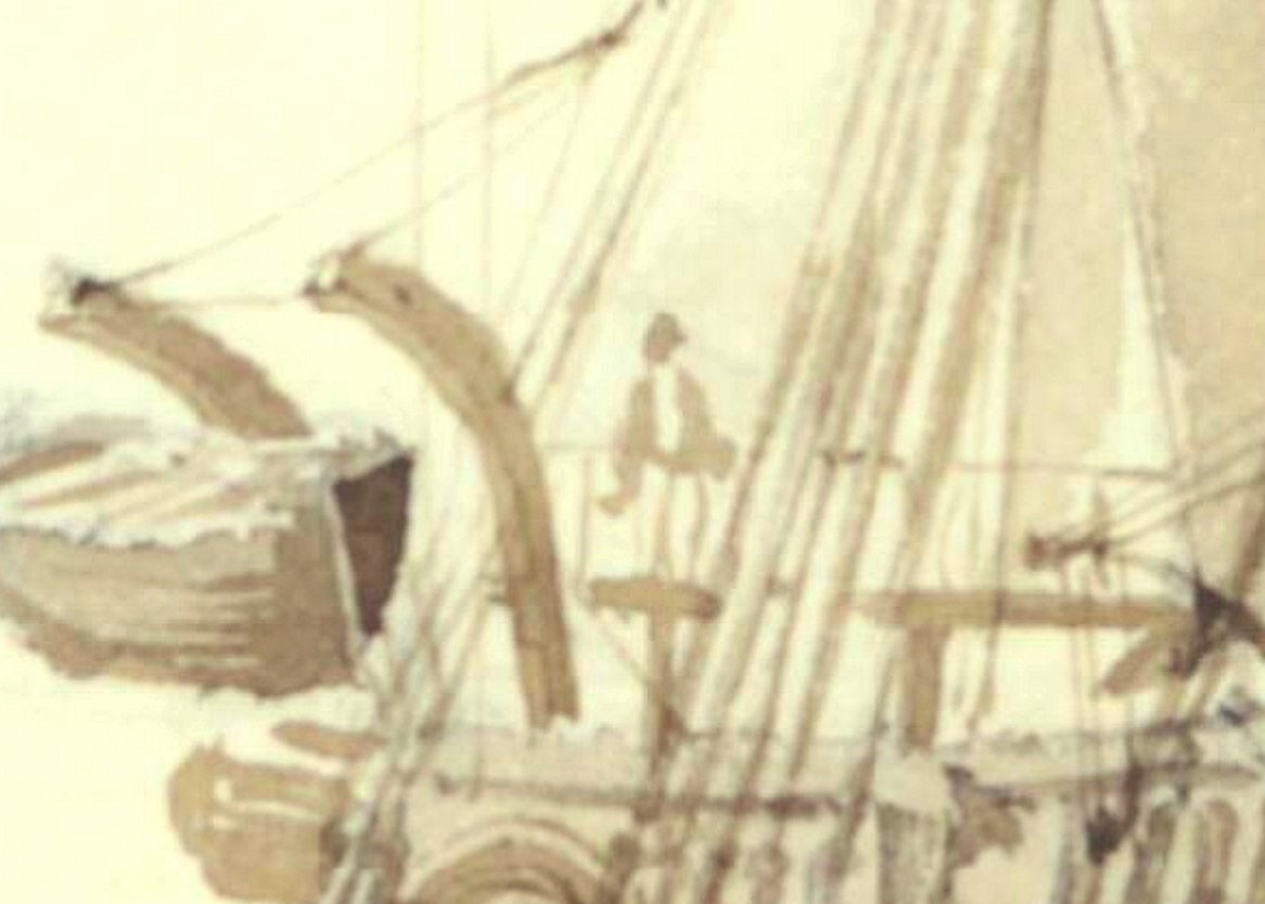
1 hour ago, clearway said:
it shows the two skid beam support posts and what looks like a diagonal rod going from the bridge end to the support post.
Kieth, first thing to remember is it's an artists impression, useful for things like curved davits, the face the bridge existed and some details like the halliards. But the davits are shown as inside the bulwarks when we're pretty sure they were outside and the davits are way out of proportion, the skid beams and post don't seem to be shown but perhaps two support posts for the bridge are? Perhaps they removed the skids and used the to operate the davits?
I agree with iron stanchions with rope handrails (that's what I tried to depict above) but how many to provide support, you could tension the rope better if you had a diagonal support at the outer posts which would need less stanchions.
Anyway, here's an enlargement of the drawing:
- clearway and Keith Black
-
2
-
I've also been playing with the bridge, it doesn't really work but I thought I'd open it up for discussion.
- clearway and Keith Black
-
2
-
1 hour ago, clearway said:
Bad part is that skid beam i put in 3 mm too far has come back to bite me
It seems to be more an issue with the kit, for it all to fit as drawn the aft side of the skid beam should almost touch the mast. I'm not sure what exactly the cause is, perhaps slightly oversize deadeyes?
I would probably shave off a few half millimeters where I could, notch the davit post so the skid beam fits flush, shave half millimeter off the skid beam, notch the skid beam another half millimeter where it meets the davit post, shave a bit more off the bridge, make the compass post a half millimeter smaller etc. The profile plan shows about a 15 inch gap between the bridge and compass post to get your head up to take a site at 1:75 call it 5mm.
2 hours ago, clearway said:Now how long to make that bridge!
Up to you but I would say the original was most likely about 42 feet.
- Keith Black and clearway
-
2
-
1 hour ago, Keith S said:
AND it makes a lot of sense.
And the more you think about it:
It answers the question as to why the bridge didn't use it as a support, it answers the question as to why a post would be put in the middle of the 'chart table', it even answers the question as to why the post was rounded.
Part of the problem we had was thinking that the table was a chart table, but would they really have taken such valuable charts on deck? Far more likely they made notes and sketches in a notebook and used those to update the charts in the cabin out of the wind and weather.
- Keith Black, clearway and Keith S
-
1
-
2
-
3 hours ago, Keith S said:
As a postscript, I have been scrutinizing the plans and I can't find any evidence that Craig is incorrect about there being a post penetrating that table for some purpose, either. (Although I admit that I originally found it preposterous that someone would punch a post through a perfectly good chart-table). I wouldn't glue the azimuth compass box down, quite yet. Maybe it is not a co-incidence that the size of the box and the diameter of that mystery post are roughly equivalent. Let's do more research on Azimuth compasses and their use, and then debate about it some more.
If that post turns out to be some kind of mounting structure for the azimuth compass, AND it turns out that the azimuth compass is for steering as well as observing, it might solve the problem of where to put the ship's compass in general!
I did a search on 19th Century Azimuth compasses yesterday and most had sights for taking bearings. The post is too tall to take bearings while standing on the deck and too low for taking bearings from the bridge so I hypothesise (one of those 'middle of the night' thoughts) that the table is actually a platform to stand on while taking bearings, giving 360° views with a higher line of sight. It also explains why the post comes through the middle of the table.
It would be impractical for it to be used by the helmsman so I think that puzzle remains.
- Keith Black and clearway
-
2
-
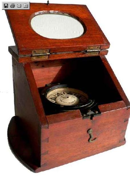
1 hour ago, Keith S said:
The azimuth compass is a bit of kit that comes in a box and looks a bit like an old-fashioned pilot's astrocompass.
Thanks for the confirmation, that's pretty much what I envisioned.
1 hour ago, Keith S said:That vertical post is likely one of a pair that sit on each side of he compass/map table
The deck plan shows a single post coming up through the middle of the table, the profile shows it squared at that point then round or fluted then squared again at the top.
1 hour ago, Keith S said:The beams and bridge being crowned on the original would make outboard AND inboard support necessary.
While the beams are crowned, the bridge is depicted somewhere about midships and the same height as it would be if supported by the outboard post so I suspect it wasn't crowned. Crowned would give it more strength at midships but I think it would be bouncer at the ends (not sure).
1 hour ago, Keith S said:The older drawings showing the skid beam are consistent with the beam being supported by brackets on the davit posts, and I would say Keith (other Keith) has got it right on his model, except the forward supports on the aft skid beam (if that makes sense) I think are outboard of the gunwale.
I agree, that's what it shows. Even though four inches thick, three or four supports feels better to me. As it stands even with supports outboard of the bulwarks you would be standing seven to eight feet from the last support. But that was probably OK in calm conditions.
1 hour ago, Keith S said:Generally, on the side-drawing you are referencing (I have a full size photocopy of the original), anything in black ink is outboard of the bulwarks, and red ink is inboard.
I tend to think of Black as viable (unless dashed) so mostly outboard but note the masts are Black, Red is nominally a midships section but does show other inboard details, Red is also used for alterations but there is usually a notation about the alteration somewhere on the plan (but it still gets confusing). They needed more ink colours.
- Keith Black and clearway
-
2
-
8 minutes ago, clearway said:
I suppose this is a case of hindsight is a wonderful thing!
Can be a wonderful thing, but all to often disappointing
If only I had bought Bitcoin when it first came out. 
- Keith Black and clearway
-
2
-
1 hour ago, clearway said:
and Craig we dont need more Keiths as we have already been confusing people
Hmmm, I'm not sure if that's a relief or not, we have three Craig's in the family (two by marriage).
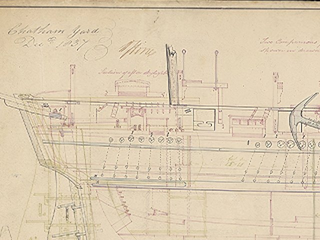
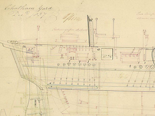
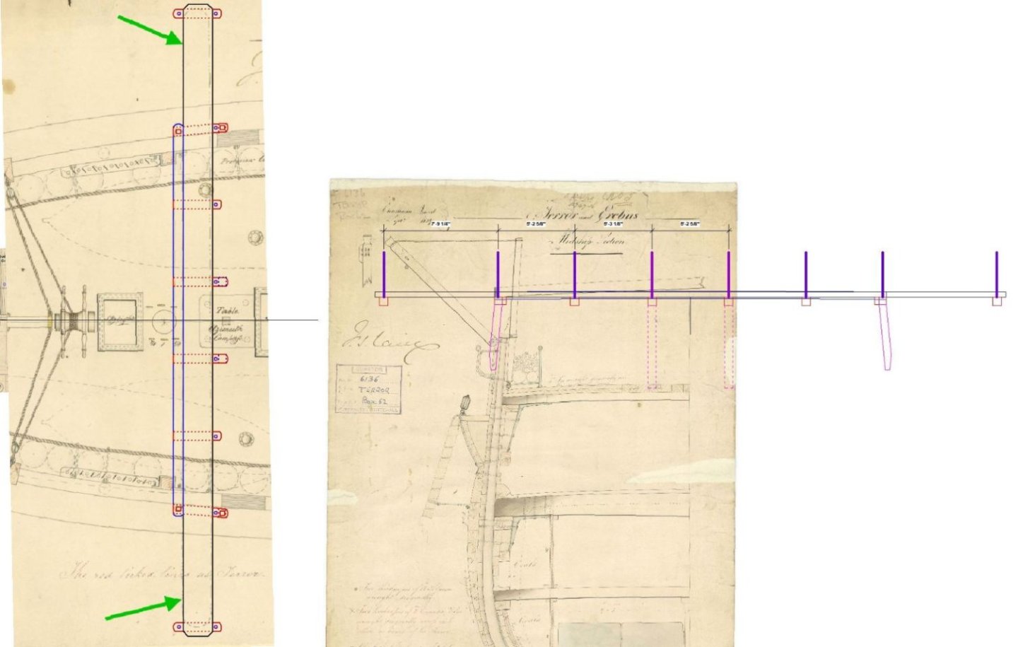
I finally looked at the earlier drawing (ZAZ5674 1837) which shows a support outboard bolted(?) under an extended skid and reaching to (my) outboard post. No other supports are shown but that doesn't mean there aren't any. Perhaps one between the skid and the 'compass post'?
This will be problematic for you as you have moved the davits forward to clear the shrouds. You could perhaps put the davit outboard of the support post ??? If you choose to put outboard supports in.
_RMG_J1408cc2.png.2625f77adf77a790df28daa62416615c.png)
-
First off, do I need to change my name to Keith?
42 minutes ago, clearway said:Another thought i had which Craig touched on is was the bridge in two halves?
Did I? Well the support piece(?) under the bridge would allow that, I guess that's what you mean. Any more than that and it would hit the compass post(?) (can't really be called a binnacle can it).
_Erebus_(1826)_RMG_J1407c2.thumb.png.2842c90d6a7e1911a1f7858ad634af12.png)
Sorry about all the question marks in both the text and the drawing but there are so many questions.
I assume the were detailed drawings of the bridge but all we have are those telling the shipyard where to put it.
Why the step in height between the skid beam and the bridge? As that section of the drawing is at midships it probably depicts the difference of the cambered skid beam and the flat bridge. A tripping hazard for sure.
We seem to have an outboard support post to support the forward side of the bridge, what supports the rear side? Is it a support post at all? Is it part of the original drawing? The top is about six feet above the deck.
I also realise I've been very lax in not complementing you on the work you have done, she looks great!!!
- Keith Black and clearway
-
2
-
4 hours ago, Keith Black said:
It's hard to go against a ship's drawing, I'm merely trying to introduce a bit of logic into the matter.
Logic is good, I certainly don't know how it actually was, I'm guessing too. Perhaps cross pieces under the bridge (there is such a piece on the drawing but it's function is unclear) with the stanchions outboard of the bridge itself, perhaps with a lookout either end access didn't have to be great just adequate.
As drawn it probably wasn't intended to have people continuously crossing while still providing better access than crossing the deck. It probably wasn't intended to be used in bad weather, who in their right mind would be sailing near to ice in bad weather, I expect the regular lookouts would be used to provide sufficient warning to steer well clear of ice in most conditions. I think the bridge was intended for use when sailing in close or very close proximity to ice when the ships ability to maneuver might be limited to feet or yards and communication to the helm needed to be quick and accurate. I think the length depicted, extending well outside the hull, probably with a rope 'rail' on three sides outside the bulwarks is probably what was intended. What was built, who knows.
Again, everything above is just guesses using the drawing as a guide. My guesses may indeed be wrong.
- Keith Black and clearway
-
2
-
8 minutes ago, clearway said:
The plan there i think shows the actual skid beam as opposed to bridge
For what it's worth, I agree.
However the devils advocate in me asks why have a shorter bridge if standing on the channel or the shrouds would provide the same view?
I think your stanchions look right.
- allanyed, Keith Black, clearway and 1 other
-
4

_Erebus_(1826)_RMG_J1407c2.png.4a645e56326d4505bea148d9248d345e.png)
HM Sloop Echo 1781 by VTHokiEE - 1:48 - Cross-Section
in - Build logs for subjects built 1751 - 1800
Posted
Sort of, it indicates that the chock has a beveled face so that when you fair the frame you you don't weaken it too much by making it too thin on that side at the chock. (Hope that makes sense).