


iMustBeCrazy
-
Posts
840 -
Joined
-
Last visited
Content Type
Profiles
Forums
Gallery
Events
Posts posted by iMustBeCrazy
-
-
To try to ease my headache I put together a list of plans relation to the Lapwing etc.
I don't think it worked.
-
Well, not an impossible fit. Agrees with some of the guesses I have made. But three different drawings have three different arrangements of the deadwood/keelson. And where did that trim on the transom come from?
- druxey, pointfiftytracer, bruce d and 1 other
-
 4
4
-
7 hours ago, bruce d said:
This is also from Dansk Archive. None of the text entries are help[ful for these drawings, no dates or further details.
Excellent! Brilliant! There's a 43 in the top left corner, probably when copies were made by or for the Danes. Was there a treaty at that time I wonder?
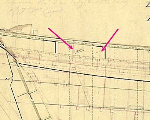
6 hours ago, Bob Portsmouth said:For the build I used 6507 as it was the clearest I could download. I didn't find any with a companionway deckhouse, just a hatchway?
On ZAZ6507 you can just make it out as indicated, it's a bit clearer on ZAZ6377 which shows both a hatch and a deckhouse.
 6 hours ago, Bob Portsmouth said:
I haven't heard previously of Bill Shoulders information?
I'm guessing he based his model on the drawings Bruce has provided.
-
-
16 minutes ago, bruce d said:
Perhaps you already have these.
Thanks Bruce, not as such. The midship section appears later than Lapwing, ZAZ6428 is dated 1817 and shows the bloody great deck beam knee I posted above. The one you've posted seems to be 1818 or later.
The deck plan/s are better quality than I have but still seem to be 1817 or later (or perhaps 'as built').
Still great to have, they will make things a little easier.
EDIT: May have been a refit as she was still in service in 1843.
-
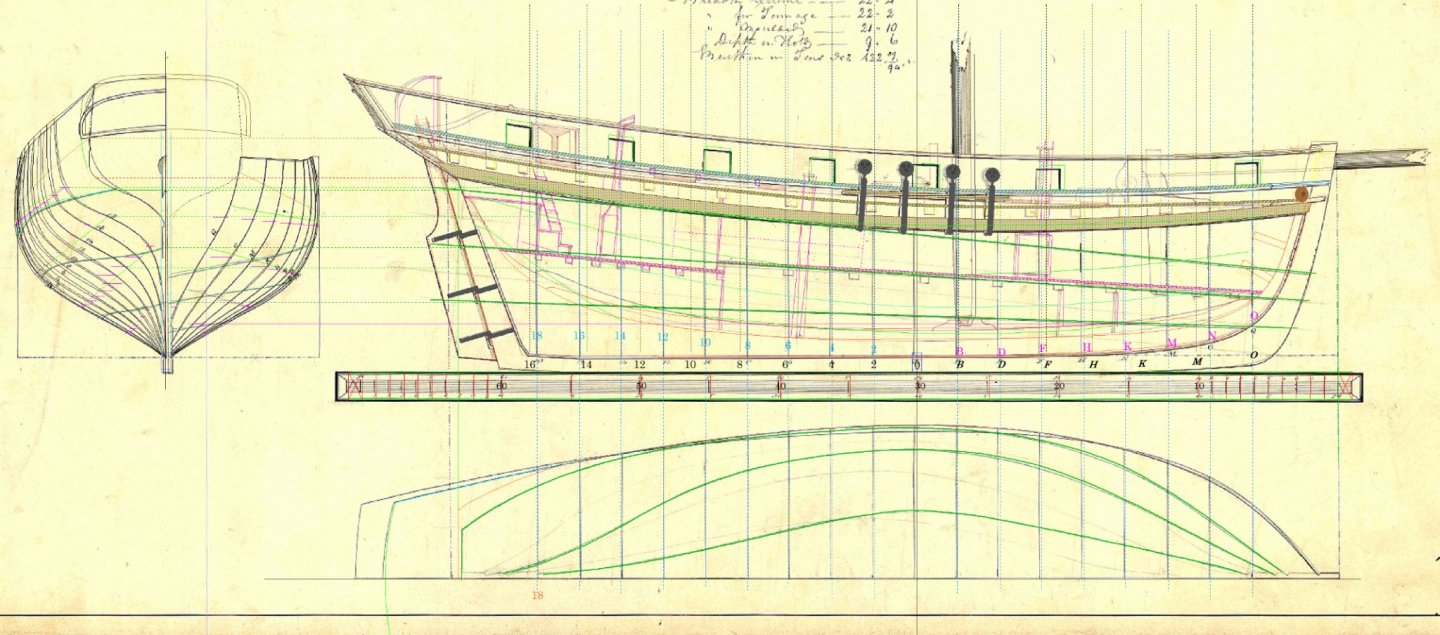
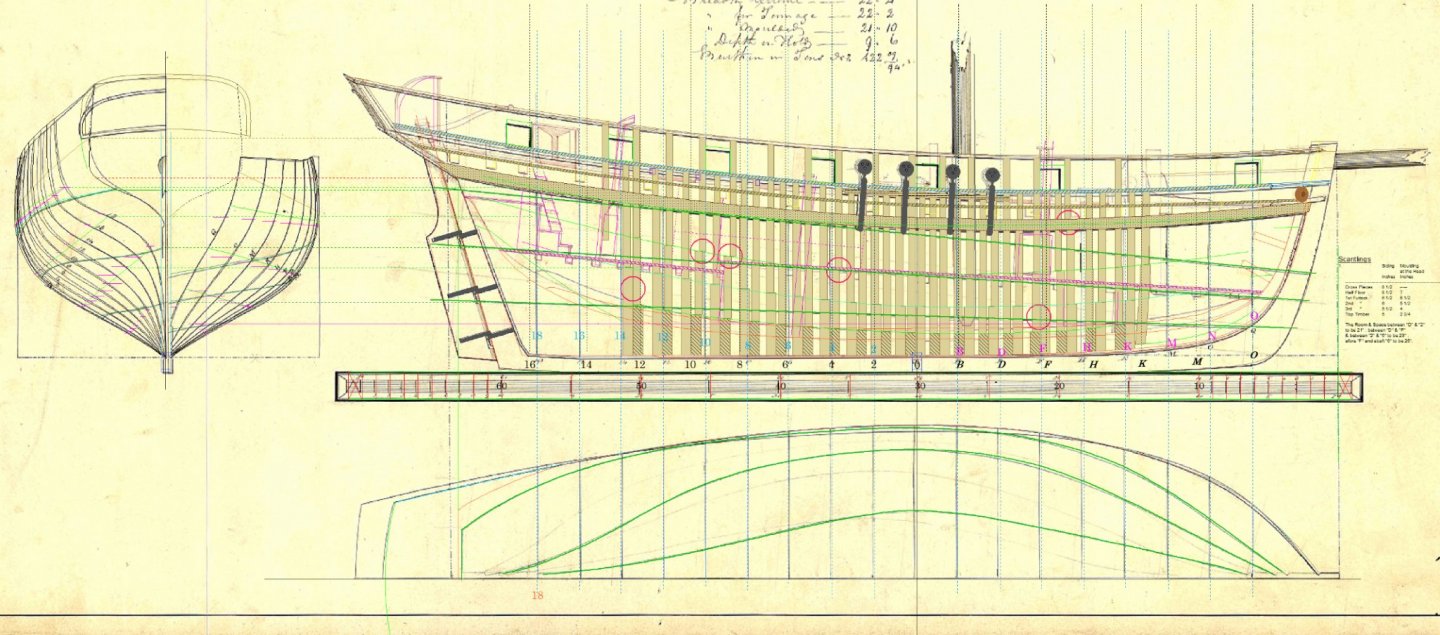
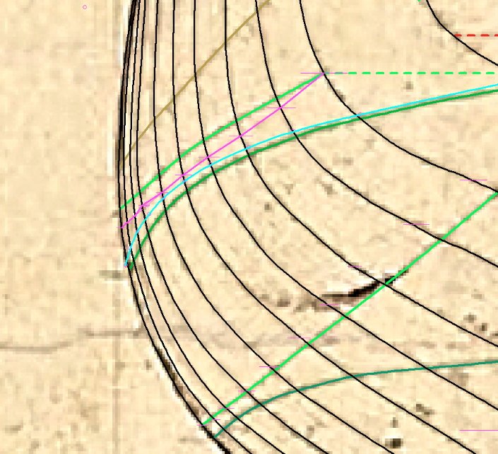
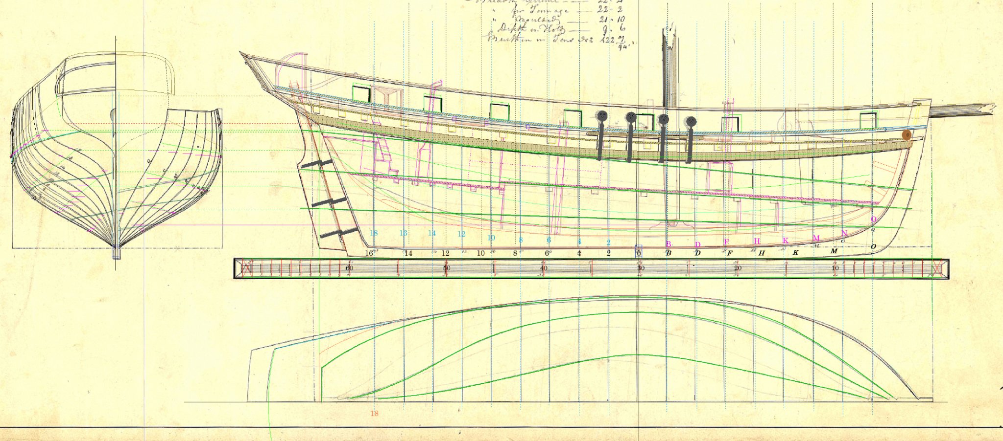
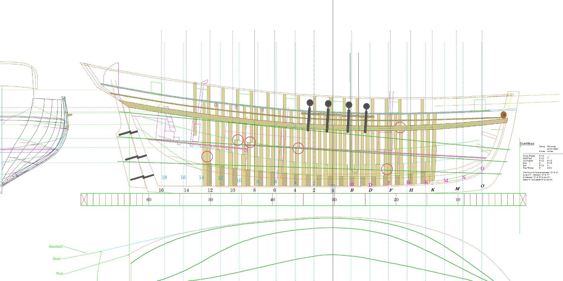
Lines from two different drawings (note the blue and black lines on the left):

Digital lofting (note, 4 is a typo for station 6 but I'll call it 4 for now): so line 4 is too far to the left, it should run through the two circles. This is indicated by the kink in the pink line. The difference is not much more than the thickness of a pencil line on the original 1/48 plans.

What I'm working from:
- mtaylor and pointfiftytracer
-
2
-
21 minutes ago, Jaager said:
but the one cross section that has any planking looks like clinker to me
Many of the photos do, must be the lighting.
21 minutes ago, Jaager said:It looks like he was planning a publication about cutters that ran aground for some reason.
The Lapwing ran aground at least twice, the outcome the last time wasn't so good. The Lapwing was on a Government mooring in Port Elliot South Australia , during a blow the harbour master had a Brig tied on astern of the Lapwing. The mooring failed and both ran aground. The Brig was saved.
22 minutes ago, Jaager said:I am guessing that schooners filled their role.
Interestingly, it seems that the Nightingale was launched as a schooner.
-
1 hour ago, Jaager said:
Bill Shoulder's plans for Speedy have it as clinker planked. Did that apply to the whole class?
What little original information I have found does not indicate that any were clinker planked.
ZAZ6429 Has some alterations noted, dated 1818, with carvel planking pencilled in suggesting that Speedy launched in 1828 was very likely carvel planked.
But that's not proof.
EDIT: Just checked his book and he says:
"She is carvel built, and carries eight 6 pounder guns. Some readers may be aware that some of these cutters were clench built, although I have no evidence to show which method was used for 'Speedy', ---------"
And as you mention class, most references give it as Nightingale class, however depending on how you classify them I suggest that the above vessels form three classes as I grouped them above:
Lapwing (First of class)
Nightingale (some alteration to frames, but I'm not sure what)
Vigilant (First of an enlarged version of the Lapwing, about 6 feet longer, allowing for an extra pair of guns)
- pointfiftytracer and mtaylor
-
2
-
Midship frame, I think it's done except for the main hatch (I haven't gotten to the decks yet).
- pointfiftytracer and mtaylor
-
2
-
Moved from another thread:
4 hours ago, Bob Portsmouth said:Hi Craig
Oh, where to start without hijacking the thread too much.
4 hours ago, Bob Portsmouth said:Diligence 1818?
I think 1823, Vigilant was the lead ship in 1821 (I think).
4 hours ago, Bob Portsmouth said:Speedy 1828
Yes, I have the plans and book but I think it's not quite right.
4 hours ago, Bob Portsmouth said:And I haven't found any above deck details for Lapwing.
Try ZAZ6430 (Lapwing see ZAZ6425-6431)
And for Diligence note the companionway 'deckhouse' on ZAZ6347.
Anyway, it's still all new to me as I only started as a family history exercise (my great great grandfather was part of the crew when Lapwing sailed to Australia in 1850).
I may build a 1/24 PoF, unrigged but showing accommodation, or I may not. Might start with some bits and pieces in MDF first. This is where I'm up to:
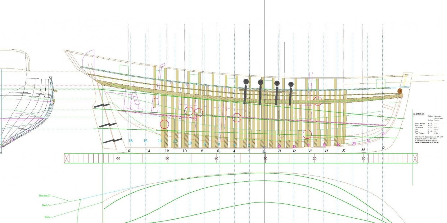
-
I am currently drawing up plans for the Lapwing which should also cover:
Lapwing 1816
Fancy 1817
Kite ca1817
Racer ca1819
Sprightly ca1819
Nightingale 1827
Speedy 1828
Snipe 1828
Vigilant 1821
Swift 1821
Basilisk 1822
Bramble 1822
-
44 minutes ago, glbarlow said:
I believe Speedy is a brig
Lots of confusion, this Speedy (1782) is a Brig on a cutter style hull, then there is Speedy (1828) which is a cutter built on the lines of the revenue cutter Lapwing (1816) which I am currently trying to produce drawings for, but it's a slow process.
-
G'Day all,
I have drawn up some scale rulers in CAD. English feet and inches in 1:16, 1:24 and 1:48. EDIT: added 1:32
When printing you may have to adjust your printers scaling until 12 feet on the 1:16 ruler is 9 inches.
After printing I cover both sides with Scotch 'Magic' tape before cutting them out.
I hope somebody finds them useful.
-
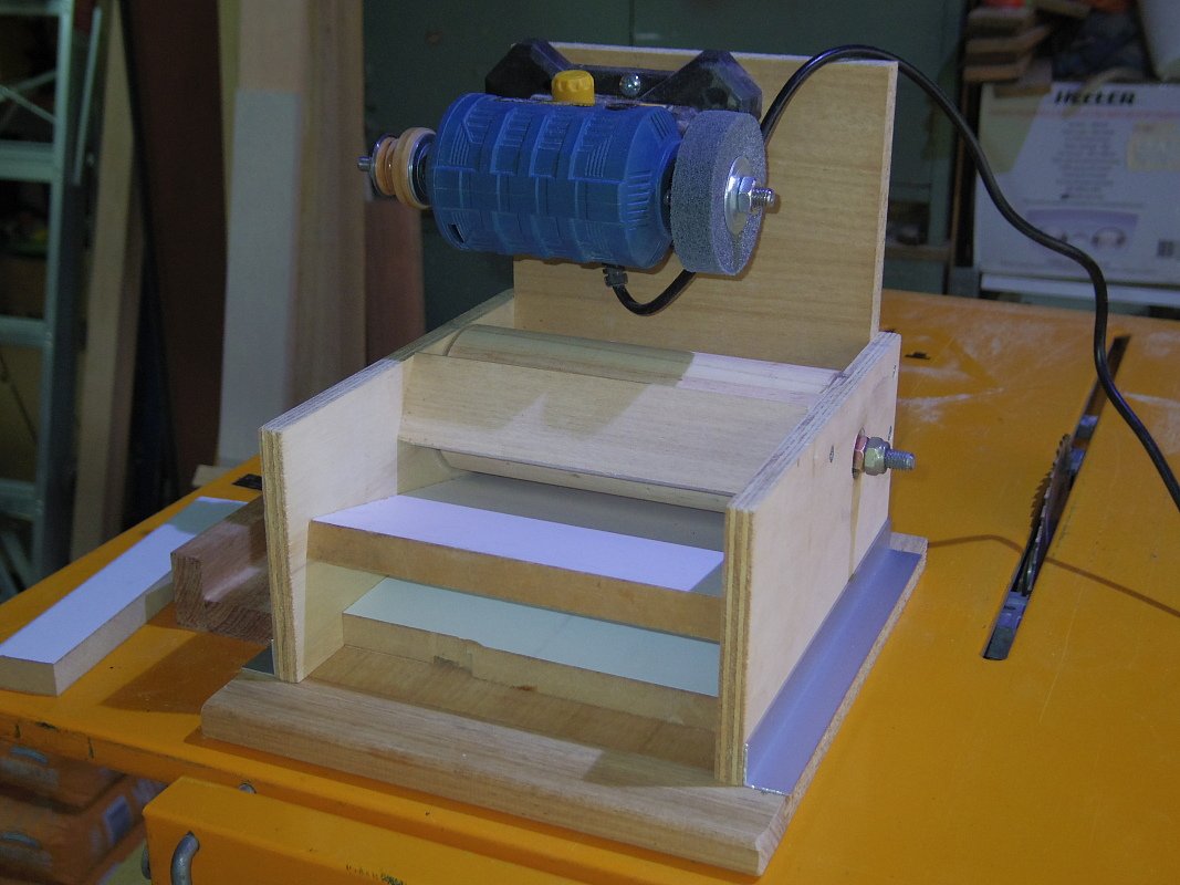
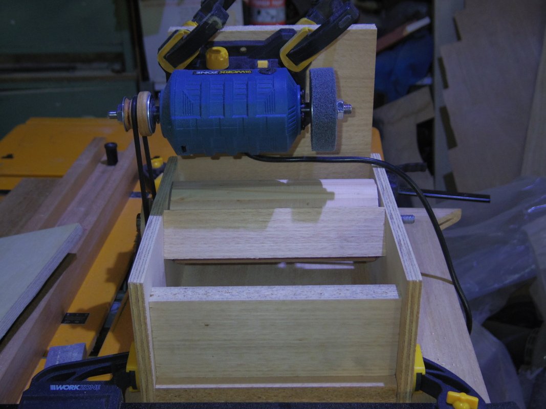
Minor update:
As is usual for this sort of project, it reaches a point where to test it you need to use it for the job you built it for and if it works you don't need it and progress stalls. So it was with this project.
However, as I can see a need in the near future I have done a little more work including safety guards and some steps towards dust extraction.
No chance of the belt hitting me in the face now.
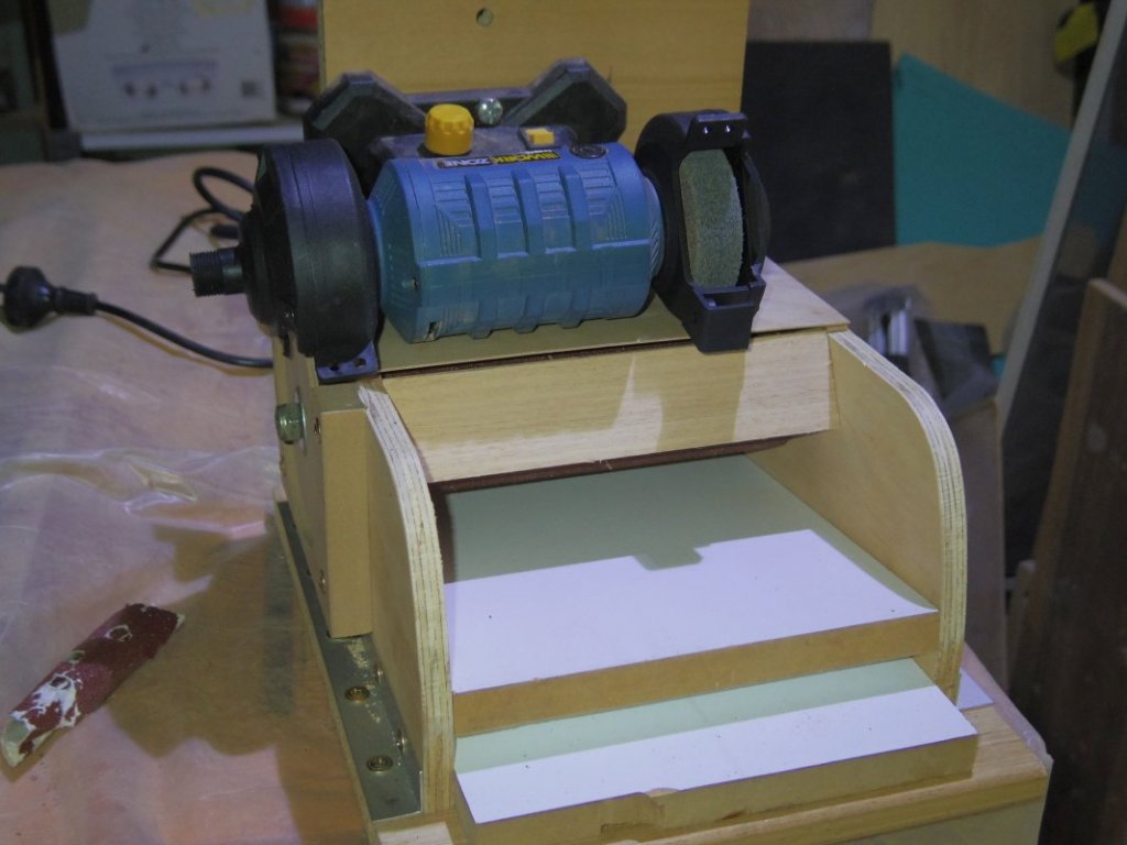
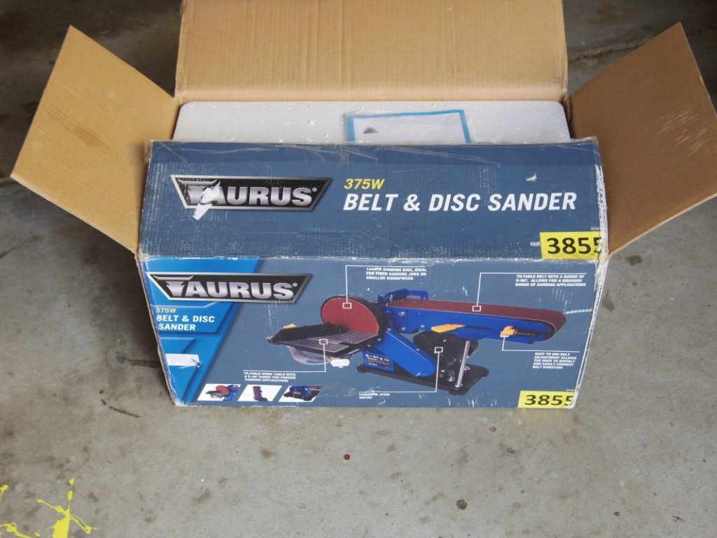
On another note, I picked up this at a market for A$20 (US$14) new in box but I'm not sure I got a bargain. It is the worst kind of Chinese product, the drill press used to drill the pulleys and sanding disk wasn't set square so they wobble, the bearings for the axle driving the belt and disk are fixed to sheet metal not the nice solid casting - if you raise the belt to vertical you tilt the disk, if you want to swap belts to a different grit you need to undo 10 screws (holding the dust cover/guard) and loosen 3 bolts. I'm sure it will be useful....... eventually.
-
24 minutes ago, pointfiftytracer said:
They are a bit clearer than what I have.
I have done or can do similar for any of the other drawings, let me know if you need something and I'll see what I can do.
-
I've played around with some of the RMG drawings, do these help?
ZAZ6345 Basilisk (1822) enlarged Lapwing j8083ab bw.tif ZAZ6345 Basilisk (1822) enlarged Lapwing j8083a.tif
-
I will certainly be following this. My interest is that an Ancestor sailed on the Lapwing on her journey to Australia and Skylark was built to the enlarged lines of the Lapwing.
Related vessels:
Lapwing (1816)
Kite
Fancy (1817)
Racer
SprightlyNightingale (1825)
Speedy (1828)
Snipe (1828)Vigilant (1821)
Swift (1821)
Basilisk (1822)
Bramble (1822)
Skylark
Diligence -
18 minutes ago, Bob Blarney said:
Btw, here's a thickness sander that I made years ago.
Nothing new under the sun is there
") 5 minutes ago, Bob Blarney said:
5 minutes ago, Bob Blarney said:This is one reason that I would make a gravity-driven sled that carries the stock through.
The only issue I can think of with a sled is that the stock tends to bow slightly as the side being sanded get hot. May not be a problem but....
-
G'day Bob,
5 hours ago, Bob Blarney said:The key points are to set the plane of the platen exactly parallel to the axis of the lathe, so as to ensure uniform thickness
I glued some sandpaper to a board and fed it through before putting sandpaper on the drum.
5 hours ago, Bob Blarney said:I think an interesting idea would be to make a 'gravity-drive' sled to carry the stock.
Interesting thought, I dismembered a laminator the other day to see if I could use the heating elements for something and I thought one of the feed rollers could be used to draw the stock out. The tilting platen makes this hard.
6 hours ago, Bob Blarney said:From the 'Days of Old'
Interesting. Physically less compact but the double taper (wedge) height adjustment would make fitting an out-take roller easier. A threaded rod parallel to the taper could be used for finer height adjustment.
- mtaylor, Canute and thibaultron
-
3
-
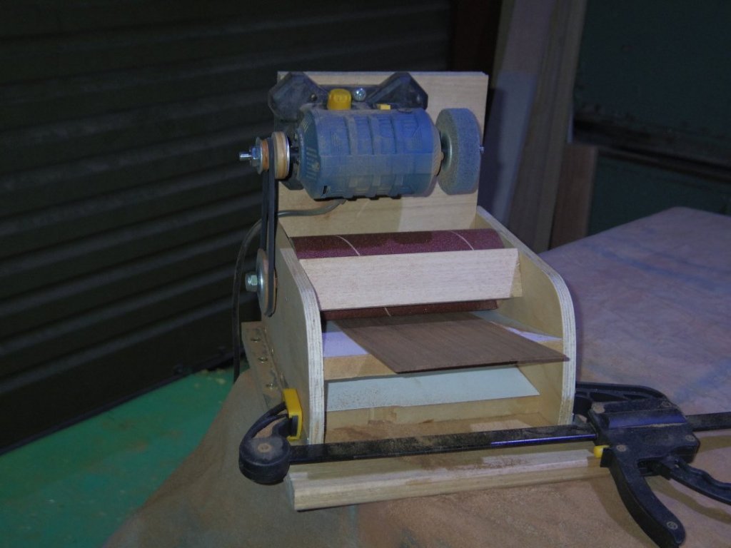
More progress,
It turns wood in to dust! But only just

It will only just take 0.25mm (0.010") of a 135mm (5.25") wide piece of cedar (western red if it matters).
I need to gear it down again, I'll try a 100mm pulley on the drum next.
Height adjustment is by pushing a wedge under the platen, this will be done with a bolt or some threaded rod when finished.
That and dust extraction will happen after I sort out the gearing.
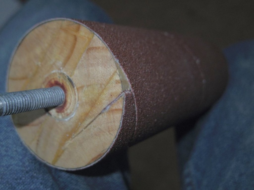
Sandpaper is attached to the drum with spray on adhesive and the ends are tucked in to slots cut with a hacksaw (see pic), seems to work.
- Jolley Roger, thibaultron, mtaylor and 3 others
-
6
-
More progress:
The drum is round, I finished up taking it out after I marked the ends and used a plane to get it closer. Still required a lot of sanding. Final sanding will be against the platen (tilt table?) to make sure it's parallel.

- Roger Pellett, bruce d, thibaultron and 1 other
-
4
-
Some progress. The drum is going to take some sanding, I have to take about 1mm of most of it.
Motor still stalls, may need a bigger pulley on the drum. One belt handles the load.

- bruce d, Jolley Roger, Cabbie and 2 others
-
5
-
G'Day Chris,
You've inspired me!
As I don't have a lathe (yet) the power plant comes first (Aldi special today):
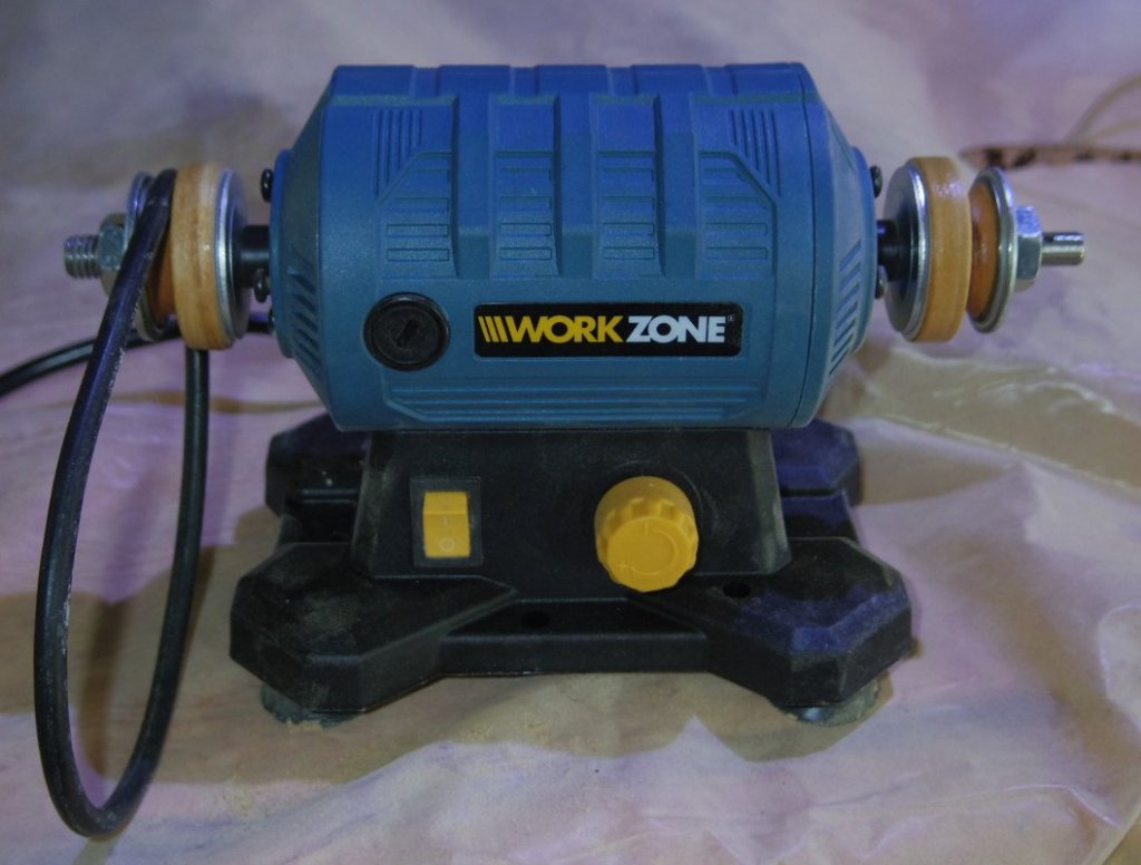
It's supposedly 150 watt but stalled when shaping the pulleys, so I will gear it to about 2:1 and see what happens. Drive belt/s will be sewing machine. One either end will give me about a 150mm sander but I'd like 200mm so maybe two belts at one end.
It will also hopefully power my yet to come DIY lathe/disk sander.
- Cabbie, bruce d and thibaultron
-
3
-


Mucking about in Fusion360
in CAD and 3D Modelling/Drafting Plans with Software
Posted
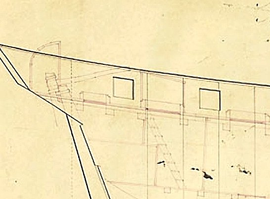
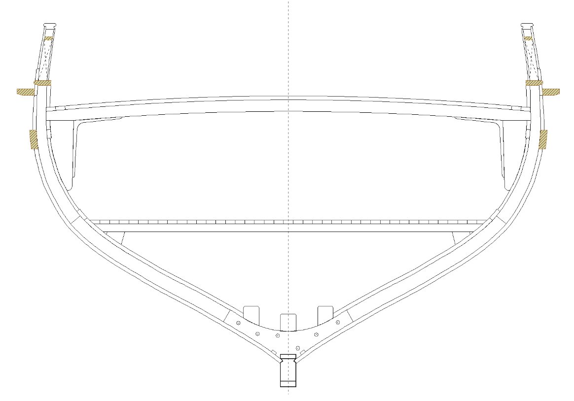
Hope you don't mind if I throw a potential spanner in the works. I'm not positive yet but it seems like the transom has those sticky out ear thingys.
I think the black lines below are the hull and the green the transom. I won't be sure until I get around to drawing the deck.