stuglo
-
Posts
707 -
Joined
-
Last visited
Content Type
Profiles
Forums
Gallery
Events
Everything posted by stuglo
-
Swan-Class Sloop by Stuglo - FINISHED - 1:48
stuglo replied to stuglo's topic in - Build logs for subjects built 1751 - 1800
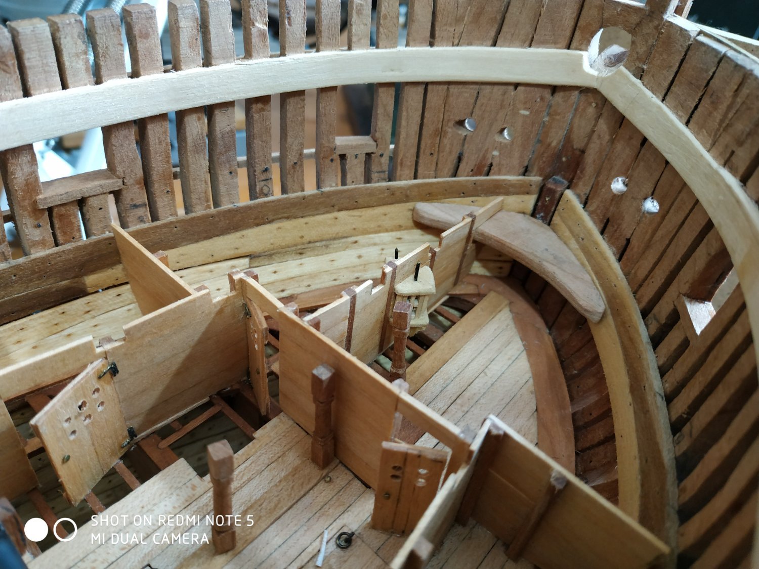
Upper Deck cont. TFFM suggests that these beams may not have been let down. Seems strange to me, but given the heights of my clamps, I don’t need to. The Carlings are generally 3.45mm wide and 2.65mm deep.( hatch covers eg are 3.84x3.18) The Ledges are (also with exceptions) 1.86mm wide and 1.6mm deep. The Hanging Knees (present on all beams) 3.45mm wide and shaped similarly to those of the lower deck- but varied according to hull shape.”Beam” arm 21.2mm.Hanging arm, 28.6mm. The Lodging Knees are 3.18mm wide, beam arm, 23.85mm and hull arm length determined by distance between adjacent beams. Aft end is notched to allow the Hanging Knee to fit against the hull. Non-glued corners are chamfered. Beam #2 Fore- there are 2 pairs of Carlings angled towards the Hull. Some trimming of the bulkheads is necessary. Between #2 Beam and #3 Beam, there are a pair of Carlings.(part of the Fore Mast Partners structure) 4.24mmX2.65mm deep, and set 12.72mm apart. These Carlings are Half Joined (recessed) under the beams #2 and#3, so that they sit with the upper surface 0.53mm below the surface of the beams. As the Beam thickness is 3.71, leaving the required 0.53mm will require mortissing of the ends of the Carlings as well. I milled off 1.71mm from the underside of the beams, and 1.47mm from the ends of the Carlings (The construction of the Fore Mast Partners are somewhat complex and only understood by reference to the 3D rendition). The various mortisses are milled before fixing: slightly narrower than necessary, so that some final alignment can be accommodated,with a chisel scalpel. I then fitted the Beam, made the lodging Knees from their pattern, with their mortises, and fitted them. Then used the general pattern for the Hanging Knees, fitted and fixed. Finally, Carlings and the various Ledges.(The outer ledges are wider than usual-I made them at 3mm.).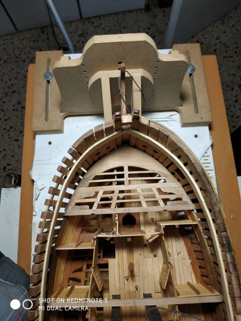
-
Swan-Class Sloop by Stuglo - FINISHED - 1:48
stuglo replied to stuglo's topic in - Build logs for subjects built 1751 - 1800
Still problems uploading , so separate post
-
Swan-Class Sloop by Stuglo - FINISHED - 1:48
stuglo replied to stuglo's topic in - Build logs for subjects built 1751 - 1800
Upper Deck Hook Similar to that fitted for the lower deck- incl. An Eking either side Thickness 4.24mm -0.53mm more than the Ekings. Therefore Let Down by the same amount as it sits on the Clamp. Both upper and lower aft edges are chamfered. Again using pattern, card shaped to size and transferred to the blank. Make Ekings similarly, remembering the blanks are 3.71mm. These are stuck to the Hook while off the model-surface being in line. Due to the RoundingUp of the beams, the upper surface of the ensemble will need some shaping and TFFM says the underside follows suit. It also suggests to allow some extra thickness of the Hook blank for this, but I (?cheated) and reduced the let down and will sand to form when the first few fore beams and structures are fitted. Went ahead and glued in place before making mortises carling and ledges, which may have been easier. Upper Deck Beams Previously made to enable placement of Posts and Bulkheads. 4.77 mm wide and 3.71 thick -Rounded Up to equivalent of 3.18mm for longest beam. ** Mark centre line on beams equidistant from hull sided and NOT centre of beam itself- simple string fore-aft.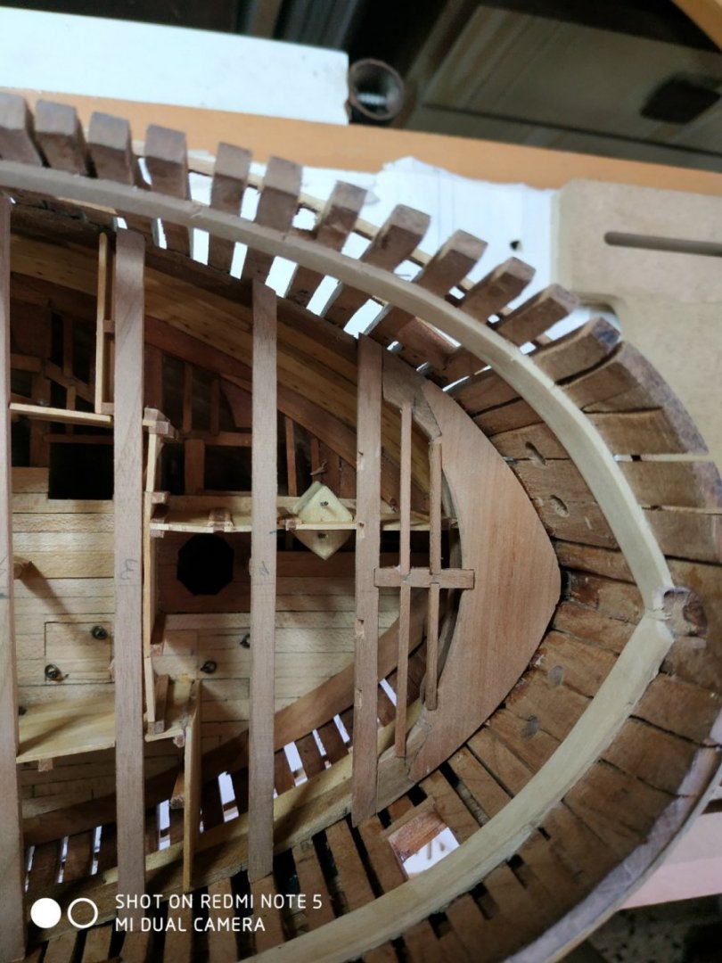
-
Swan-Class Sloop by Stuglo - FINISHED - 1:48
stuglo replied to stuglo's topic in - Build logs for subjects built 1751 - 1800
Lower Deck Breast Hook Actually, above the lower deck. Required temp. removal of foremost bulkhead. The upper surface is 16.43mm above the lower deck planks,sitting in the uppermost mortise of the Stemson, and lies horizontally. Blank of 4.24mm. Trial fitting with printed plan and card. The upper and lower aft edges are chamfered. The Bulkhead replaced, with a cut out to accommodate the Hook.thumb.jpg.357ba633dce490986cf4afb2a3fcbd57.jpg)

- 475 replies
-
- 12
-

-
Swan-Class Sloop by Stuglo - FINISHED - 1:48
stuglo replied to stuglo's topic in - Build logs for subjects built 1751 - 1800
Tried it once, made a mess, but I will try again ( It was charcoal powder used by artists. My good friend Shota, says he was successful with just a small amount of powder in the PVA glue.) -
Swan-Class Sloop by Stuglo - FINISHED - 1:48
stuglo replied to stuglo's topic in - Build logs for subjects built 1751 - 1800
.jpg.090fa49d7ae5512d776b49d7af1cbccf.jpg)
-
Swan-Class Sloop by Stuglo - FINISHED - 1:48
stuglo replied to stuglo's topic in - Build logs for subjects built 1751 - 1800
The Rudder 2 main pieces, fore and aft (blade). The joint between them (Tabling) is simplified to a male/female arrangement. There is also a narrow backing piece aft, and a Sole piece,similar to a false keel. Interestingly, TFFM points out that the lowest point of the rudder is higher than the false keel. **How many models have I strived to make it in line !! Ignorance is not always bliss!!** Using 12mm stock, with paper pattern cut-outs, make the 2 main pieces. I milled out the tabling. I left the base slightly overlong as suggested. TFFM suggests using black paper between joints, but previous experience was not so good for me- the wood sticks to the paper, which then separates-perhaps a different card-type would be better. Anyway, I opted for epoxy, which leaves a black joint line, albeit thinner. A Backing piece was similarly affixed. Cut-outs for the pintles(5) are next. Note not all are the same length. Their position should be checked to match the grooves in the sterpost, but the head of the rudder is still too big to fit through the port- a ruler and a prayer will have to suffice. Again milled,+ with a curved piece for the bottom edge. **Having looked ahead at the pintles, I realize I can’t make them as suggested, so I shortened the recess by 1.5mm-explaination next post** The narrow notches on the aft aspect were drilled and finished with a scalpel. 5 bolts into the blade from aft, between each Pintle strap, and below the lowest. A square mortise in the middle of the rudder head (fore/aft) is made at right angle to fore surface, 4.77mm tapering to 3.71mm at exit on aft surface. This I made by drilling out (press) a 3.4 hole and using a succession of square files. Now a Bearding Line- tapering somewhat downwards, is shown on the pattern. Note its changing relation to the pintle recesses. Either side is filed to a central line on the fore surface. So looking end-on, it appears as a flattened triangle. The beard line stops a few mm short of the mortise in the Head, But looking ahead this appears not to leave enough room for the Head hoops, if more than 1 is fitted below the mortise. The Rudder now needs to be tapered to match the taper of the Stern Post -7.99mm to 5.5mm at the keel. ( I bought a taper jig to use with a table saw for such needs, but can’t use it as the Rudder is too wide for the table saw to cut!! ) So milling at using a wedge at one end, sanding board and elbow grease. Trial fitting- some minor filing of rudder Port required. I haven’t decided how to fashion the Pintles yet, but in any case, will postpone fitting the Rudder to a later stage..thumb.jpg.00ac428d9f9ab4b62b8f7b9650269898.jpg)
.thumb.jpg.b7ab8809e64055ee9069eff42564cba1.jpg)
.thumb.jpg.c207235661d89c44ffac0fd17cb8633b.jpg)
.thumb.jpg.a25a43177820867c4a75325cb9cb78c5.jpg)
-
Swan-Class Sloop by Stuglo - FINISHED - 1:48
stuglo replied to stuglo's topic in - Build logs for subjects built 1751 - 1800
No - called locally "African Nut" . Finish with wipe-on poly -
Swan-Class Sloop by Stuglo - FINISHED - 1:48
stuglo replied to stuglo's topic in - Build logs for subjects built 1751 - 1800
-
Swan-Class Sloop by Stuglo - FINISHED - 1:48
stuglo replied to stuglo's topic in - Build logs for subjects built 1751 - 1800
Strakes #30-32 “Planks upon the drifts”-between sheer strake and top of side. Thickness 1.06mm Looking at the 3D rendition, NOT thicker at bow as per strakes below the Sheer strake.Also only strakes #30 and #31 forward,( there is an additional strake #32 aft) TFFM has a concise but very useful guide to painting generally, and this area in particular. Also a guide to copper plating. I dislike painting and after 3 “copper bottoms” , I can live without another. In any case, the purpose of this build is to see the wood and architecture. So, to simulate some illustration, I used a wood with a pronounced and changing grain pattern and colour - sort of impressionistic. (my wife approves) -
Swan-Class Sloop by Stuglo - FINISHED - 1:48
stuglo replied to stuglo's topic in - Build logs for subjects built 1751 - 1800
Both. Minimal alcohol as the wood flakes and clean cuts are difficult, resulting in damage to the wood I want to keep. -
Error code 200
stuglo replied to Blue Ensign's topic in Using the MSW forum - **NO MODELING CONTENT IN THIS SUB-FORUM**
Didn't work yesterday but haven't since beginning of week. Same pictures failed multiple times but others OK (direct from computer). Later, copy/paste from another site without problems -
Swan-Class Sloop by Stuglo - FINISHED - 1:48
stuglo replied to stuglo's topic in - Build logs for subjects built 1751 - 1800

-
Error code 200
stuglo replied to Blue Ensign's topic in Using the MSW forum - **NO MODELING CONTENT IN THIS SUB-FORUM**
Thanks. I thought I was just stupid until I read of others having the same problem -
Swan-Class Sloop by Stuglo - FINISHED - 1:48
stuglo replied to stuglo's topic in - Build logs for subjects built 1751 - 1800
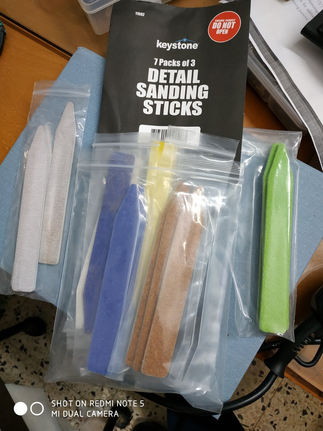
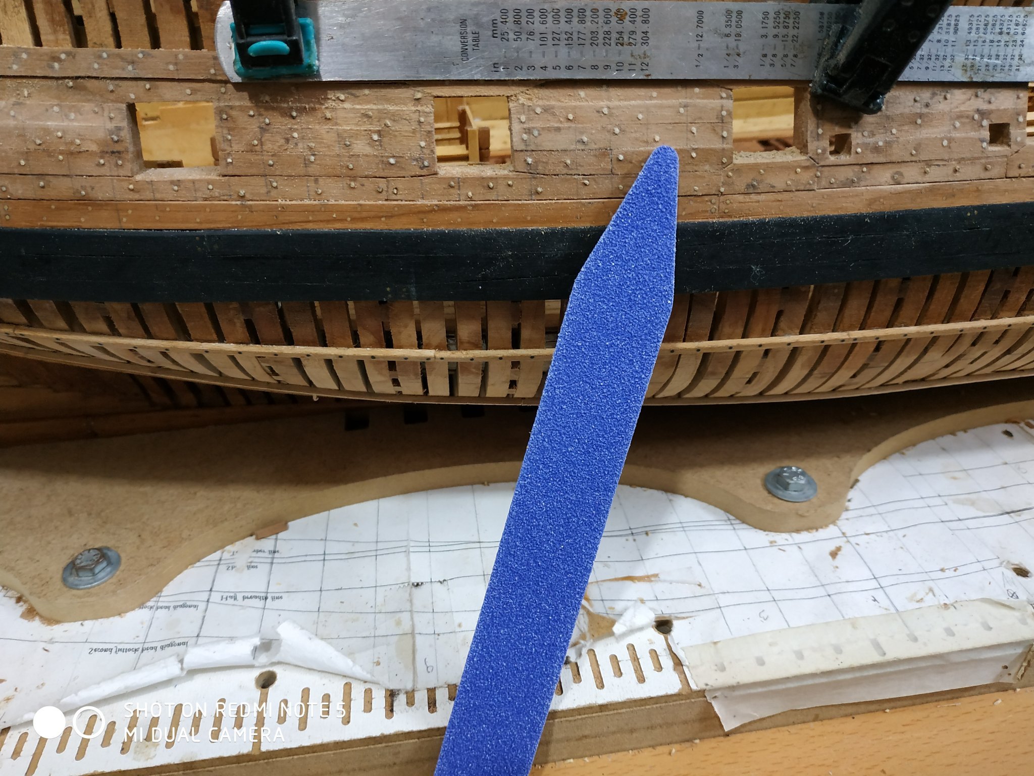
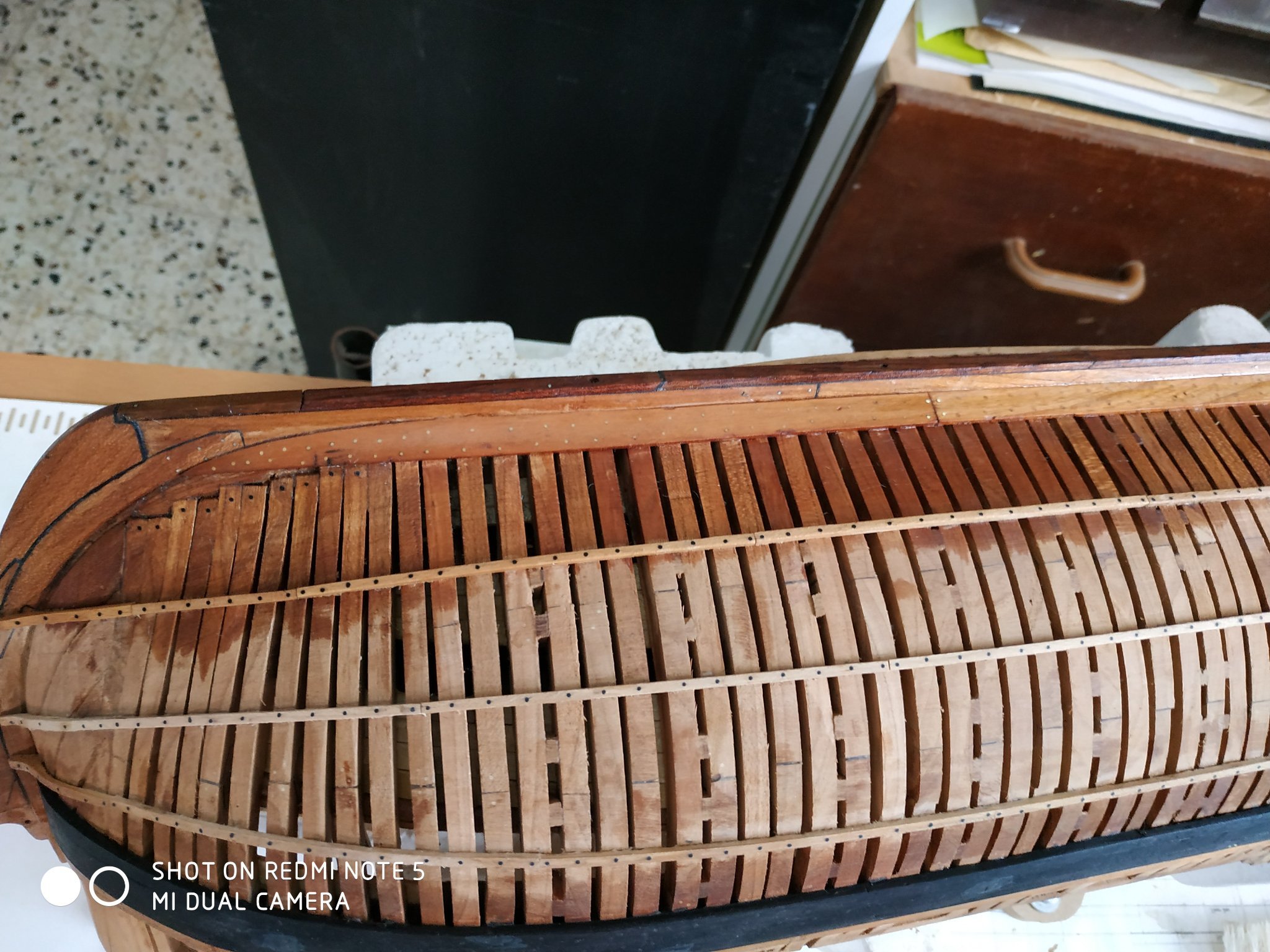
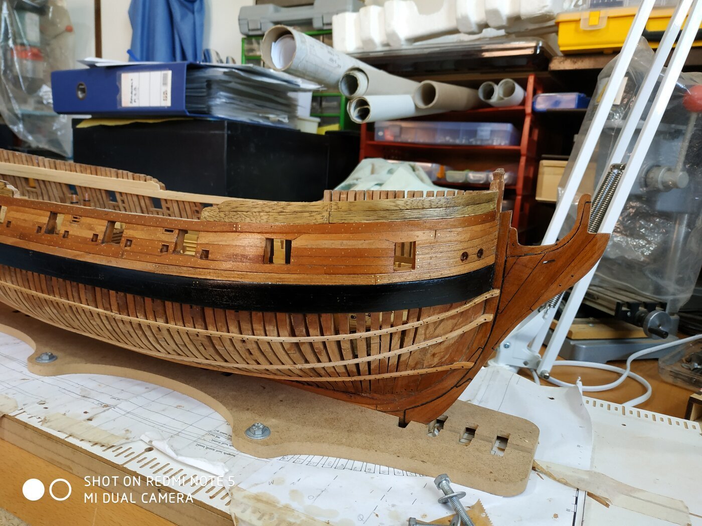
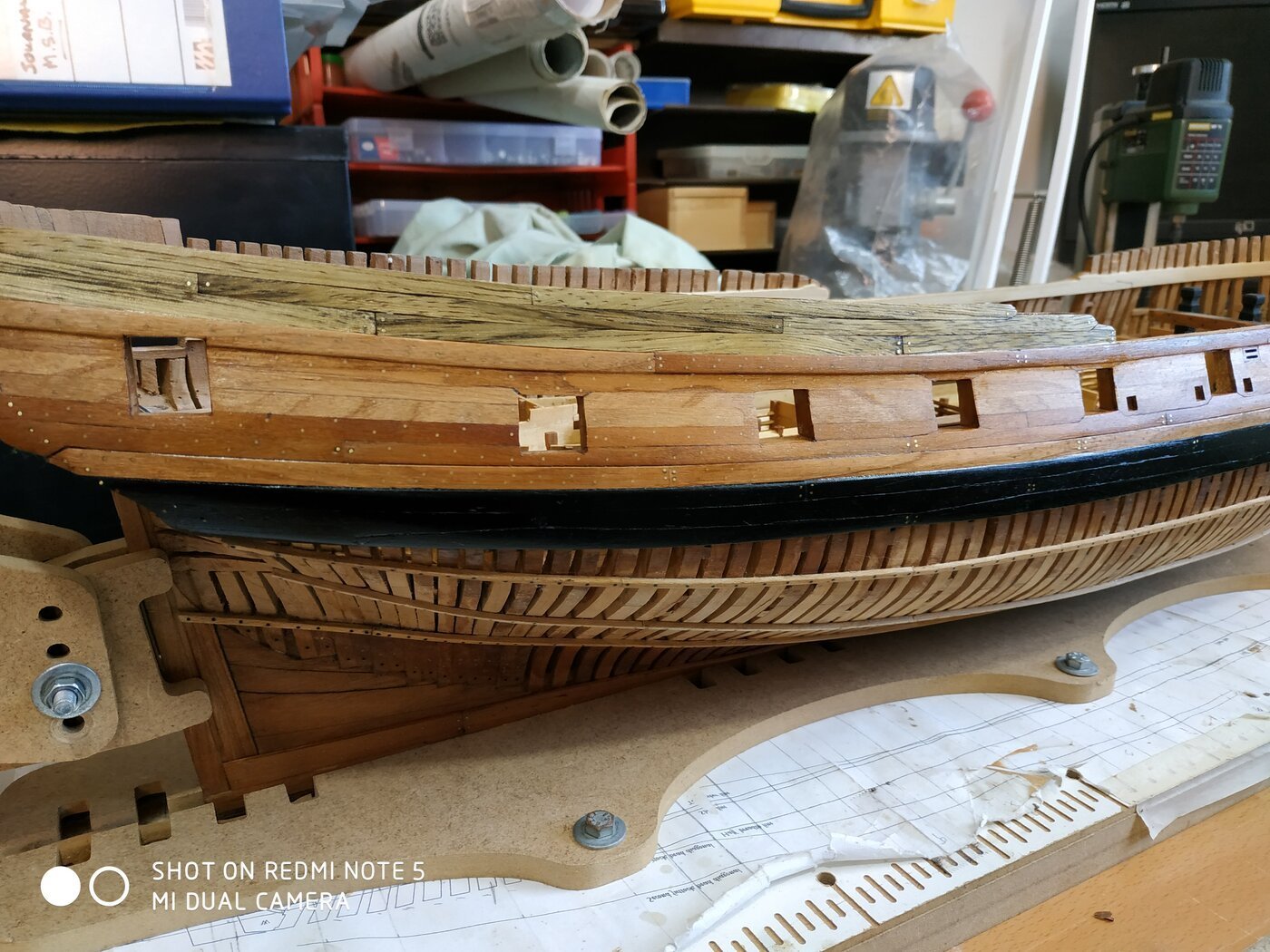
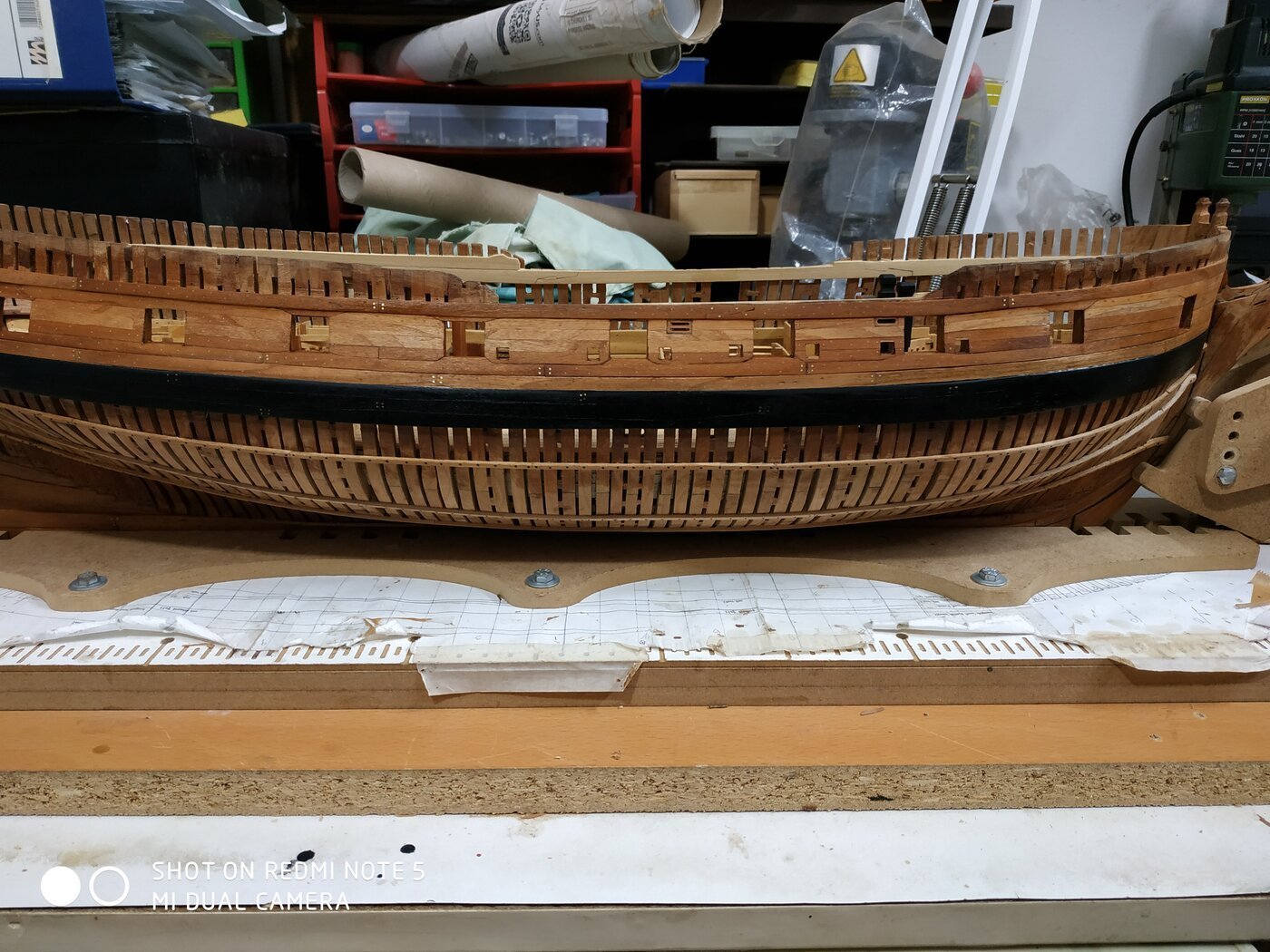
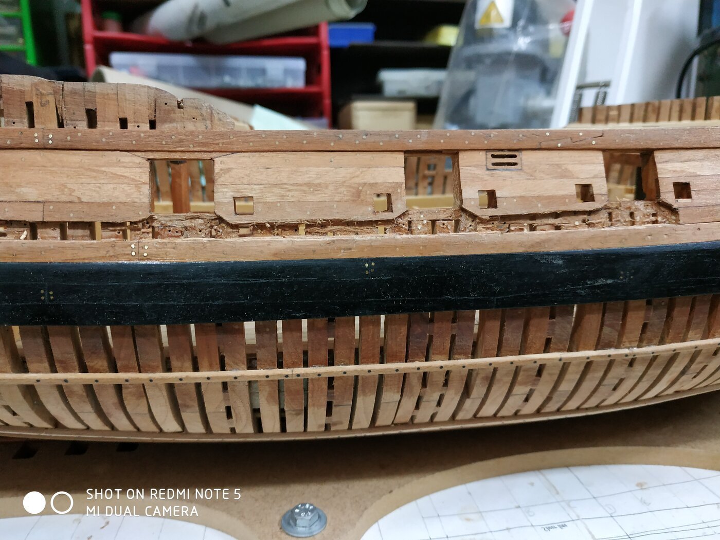
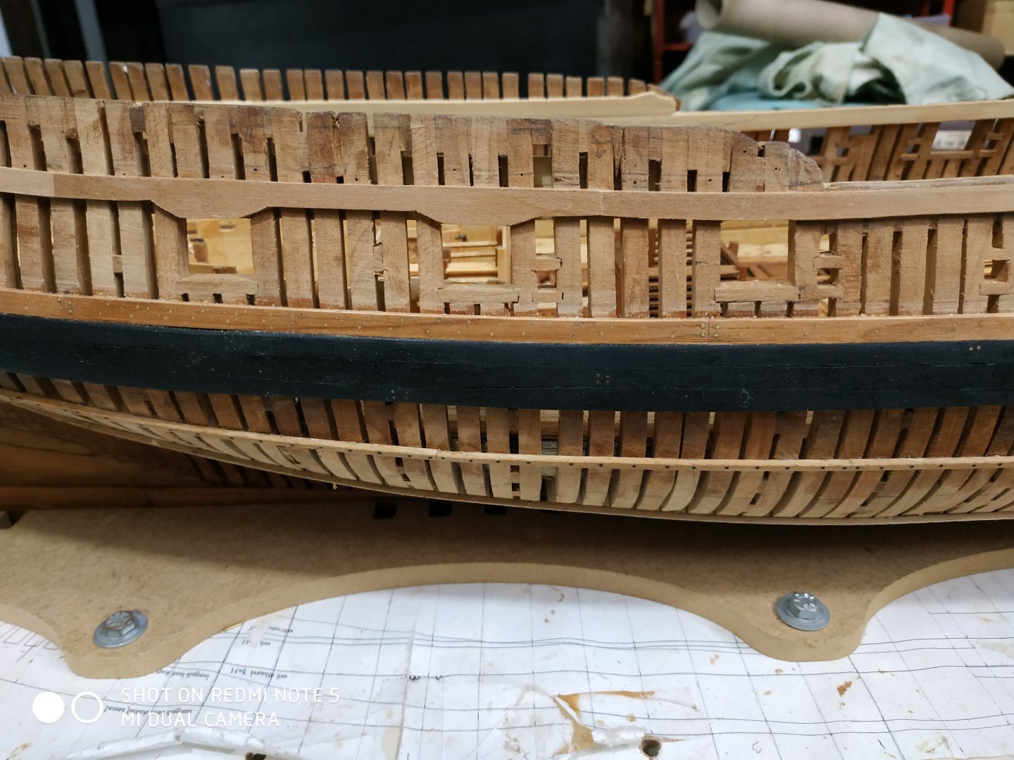
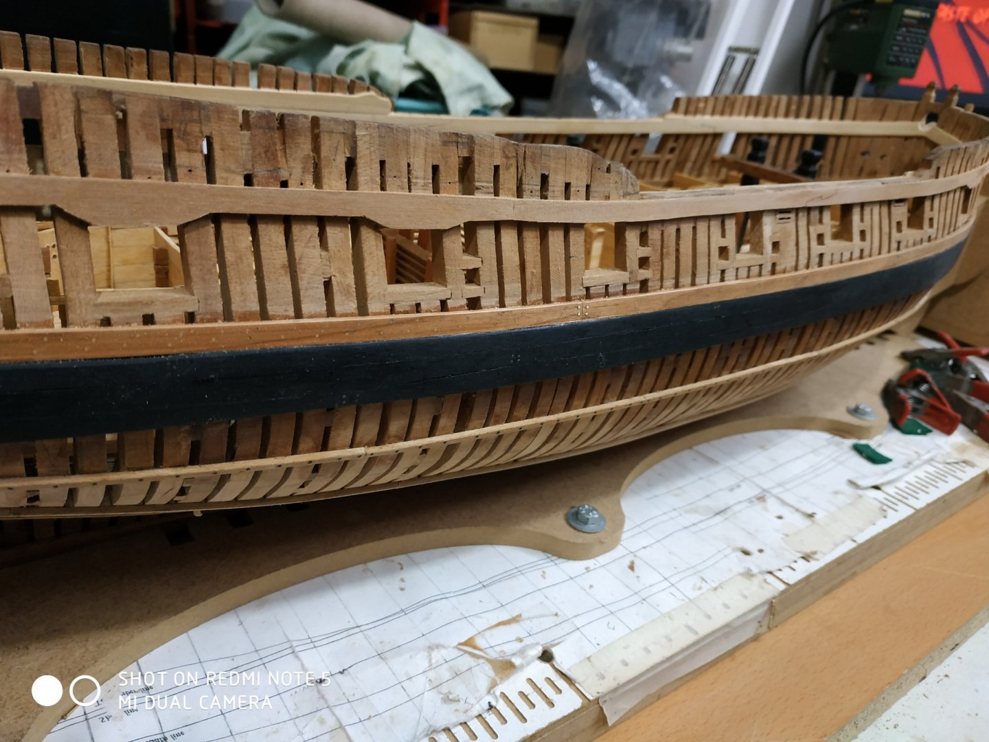
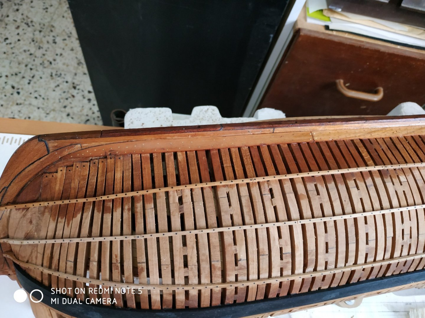
Another choice or crossroad. To fit the strakes below the Wales or not? The port side will be left “free” or open, but as displayed, will not be seen. Therefore: The Sheer Strake, #29. This is an interesting variety, as the standard width expands over those ports where the neighbouring strake would have to be narrower than 2.65mm when fitted above those ports. This is called “working down”. A sort of flap. The ports where this happen are shown(1,2,7,8), but they did not exactly match mine(1,2,6,7). (But the effect over port 1,shown on p23, is absent on p15!) The strake is 1.6 thick.and when not worked down.5.5mm wide. Positions of the butt joints are given (Kaft, Baft,6fore and 14fore) Note hook scarf joint between 2nd and 3rd part. The line runs almost parallel to Wales but not exactly. It is very important because it determines the upper line and “shape” of the ship. I took an overly wide blank strip, marked the position of ports with spare 5mm either side. The interval narrowed to required, off the model, the part glued into position. When dry, the extra width is removed until it is in line with the upper edge of the port.Then an angle appropriate to the remaining extra width, is made.(chisel). The gap between the Black strake and the Sheer strake, is filled with strakes #24-#28 (called the Stuff of the Topside) This gap is measured at various stations and divided by 5- to give an average plank width. The lowest strake is 1.9 thick and the upper is 1.06mm, and between the others are tapered- EXCEPT the bow section (foreward of the 1st port)all will be 1.6mm, matching the Black strake and Wales. The strake #25, is also worked as required by the previous rules. I failed to realize this until all finished (including treenails) , tried a repair by changing just the areas under the ports, saw it was a mess, and removed and remade the whole strake. Note that when made, the worked-down is 1.6mm thick. This has to be sanded to blend with the neighboring strakes 1.06mm. I helped the tapering by using 1.6mm stock for strakes #26 and #27. I tapered with some newly acquired sanding sticks. They work very well and are ideal in size and shape (80-400)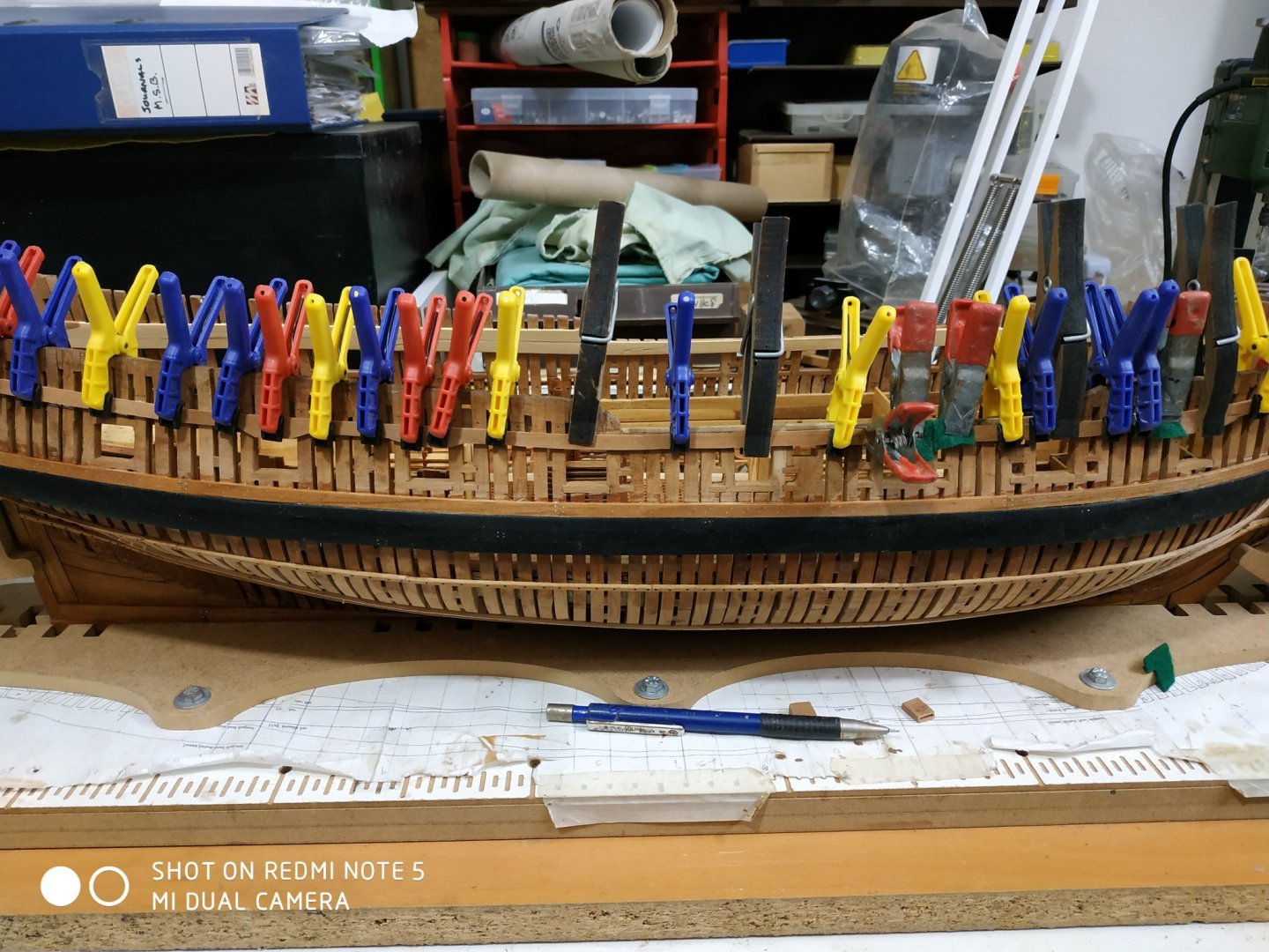


-
With the sails (or even without) this is a great model. Just have fun.
-
Bob Hunt's "Hanna Practicum" gave me the foundation and confidence to start scratch building. After 30 years of building kits, possessing and reading many books, never took me beyond this. Thanks to Bob, I am building a scratch Swan class ( also with a practicum TFFM). I never would have tried without such a positive experience. Any quibbles or critiscms pale to insignificance.
-
Swan-Class Sloop by Stuglo - FINISHED - 1:48
stuglo replied to stuglo's topic in - Build logs for subjects built 1751 - 1800
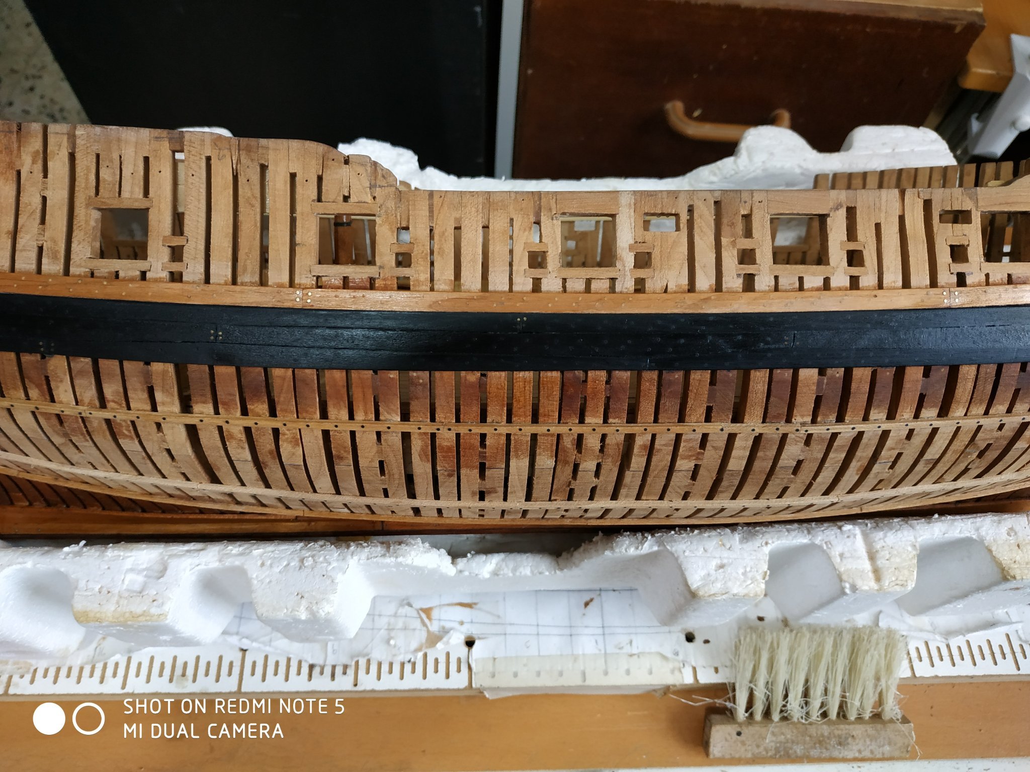
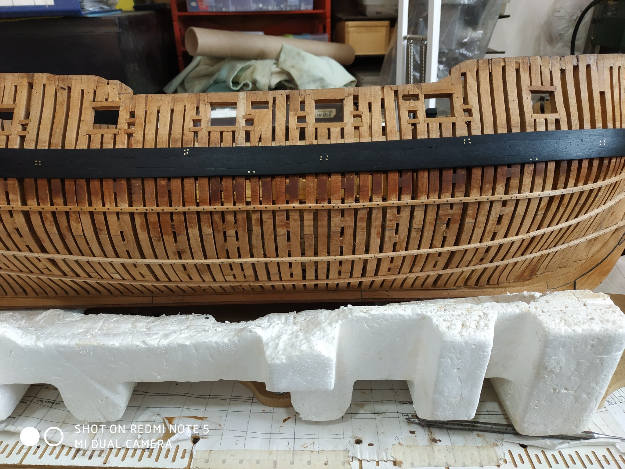
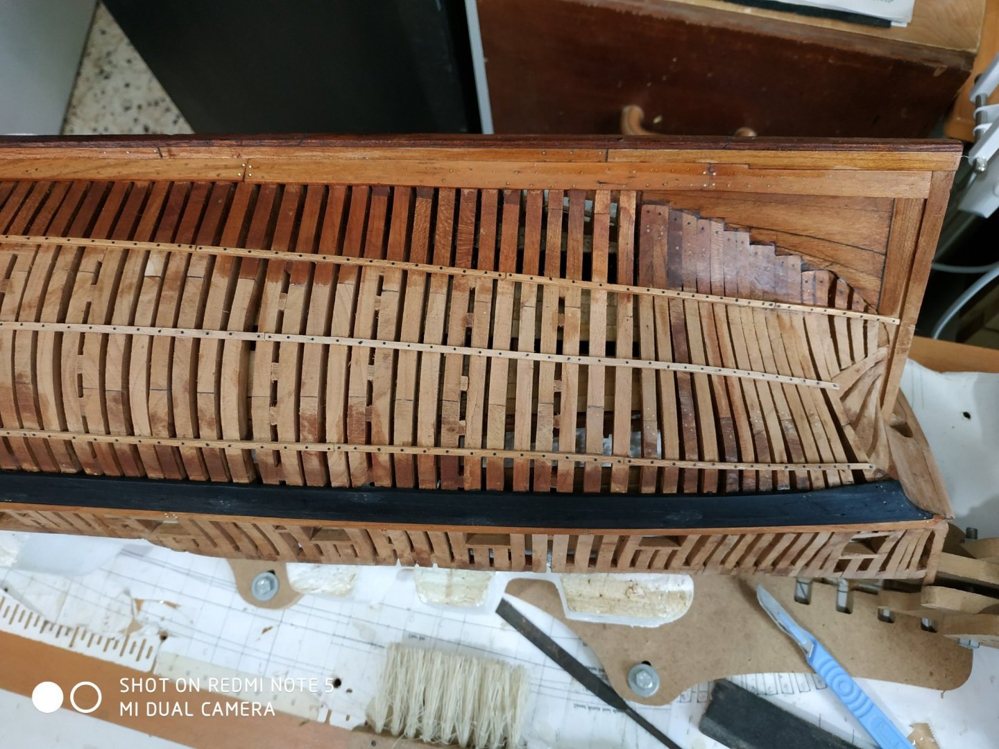
The “Black” strake, #23 The strake above the wales, is ,in fact,not black. Width 5.3x1.86mm. The butts fall on forecant 4, F aft, 14 fore. The aft ends differently- expands like a fishtail,into the neighbouring strake. Garboard Strake. I have always found this most difficult in my previous builds. TFFM gives a good explanation and particularly emphasizes the avoidance of excessive forward extension- only to forecant #3 Thickness 1.6mm with varying width. It butts on Cfore, 6fore, and below heel of cant 9. Some reworking of the rabbits required. Reviewing the 3D rendition, there is some thinning of the board as it joins the rabbits. I used wipe-on poly on these strakes to try and keep their lighter colour rather than the usual oil which allows a deepening in colour. Note I changed my mind again and dull-downed the copper nails on the Wales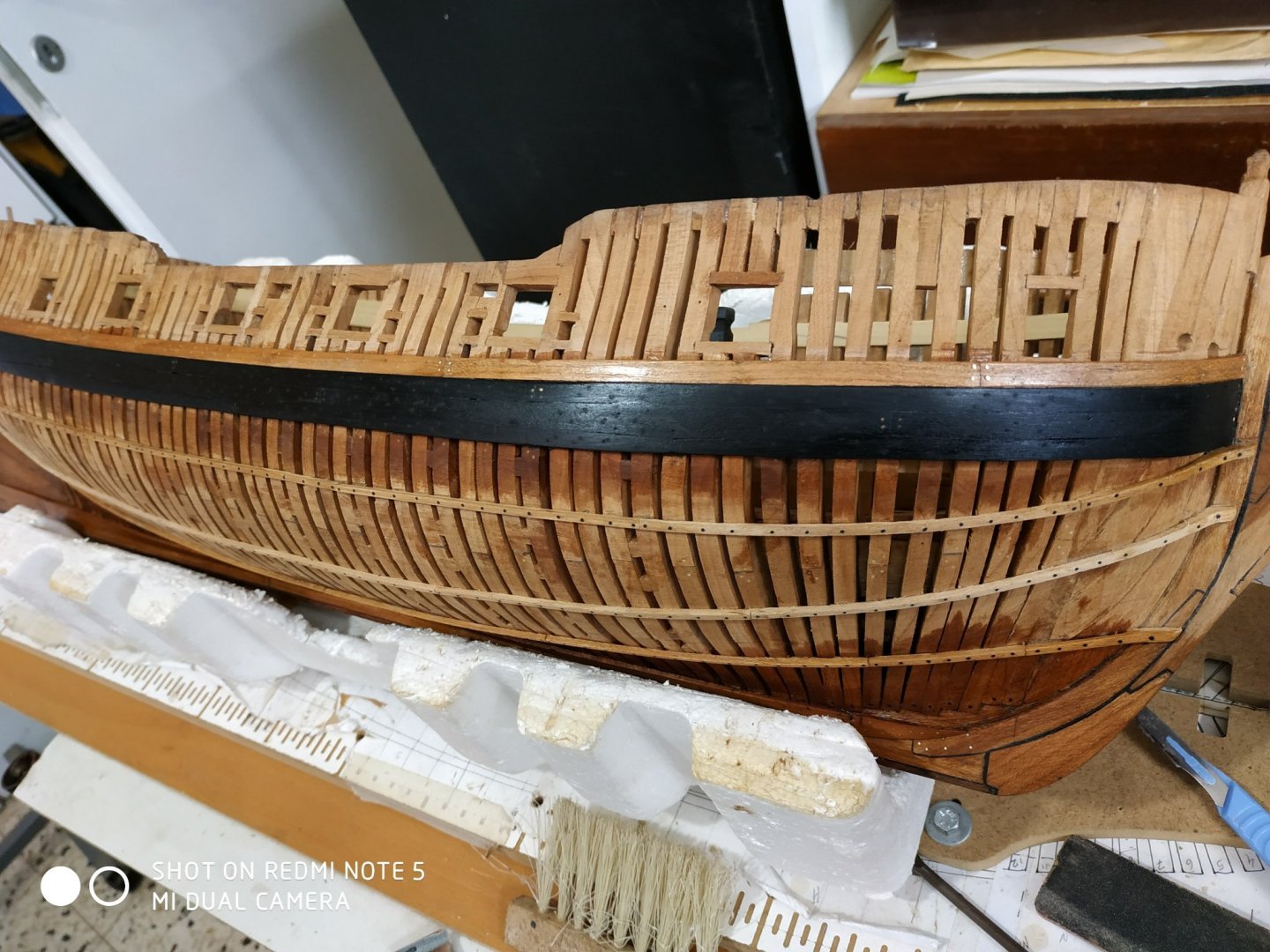

- 475 replies
-
- 10
-
-
My thanks also. Might I add that any distraction or just lowered attention (or tired "just finish this bit") is very dangerous. I nearly lost my thumb to a 10 in table saw blade last year. Stupidity is unforgiving.
-
Swan-Class Sloop by Stuglo - FINISHED - 1:48
stuglo replied to stuglo's topic in - Build logs for subjects built 1751 - 1800
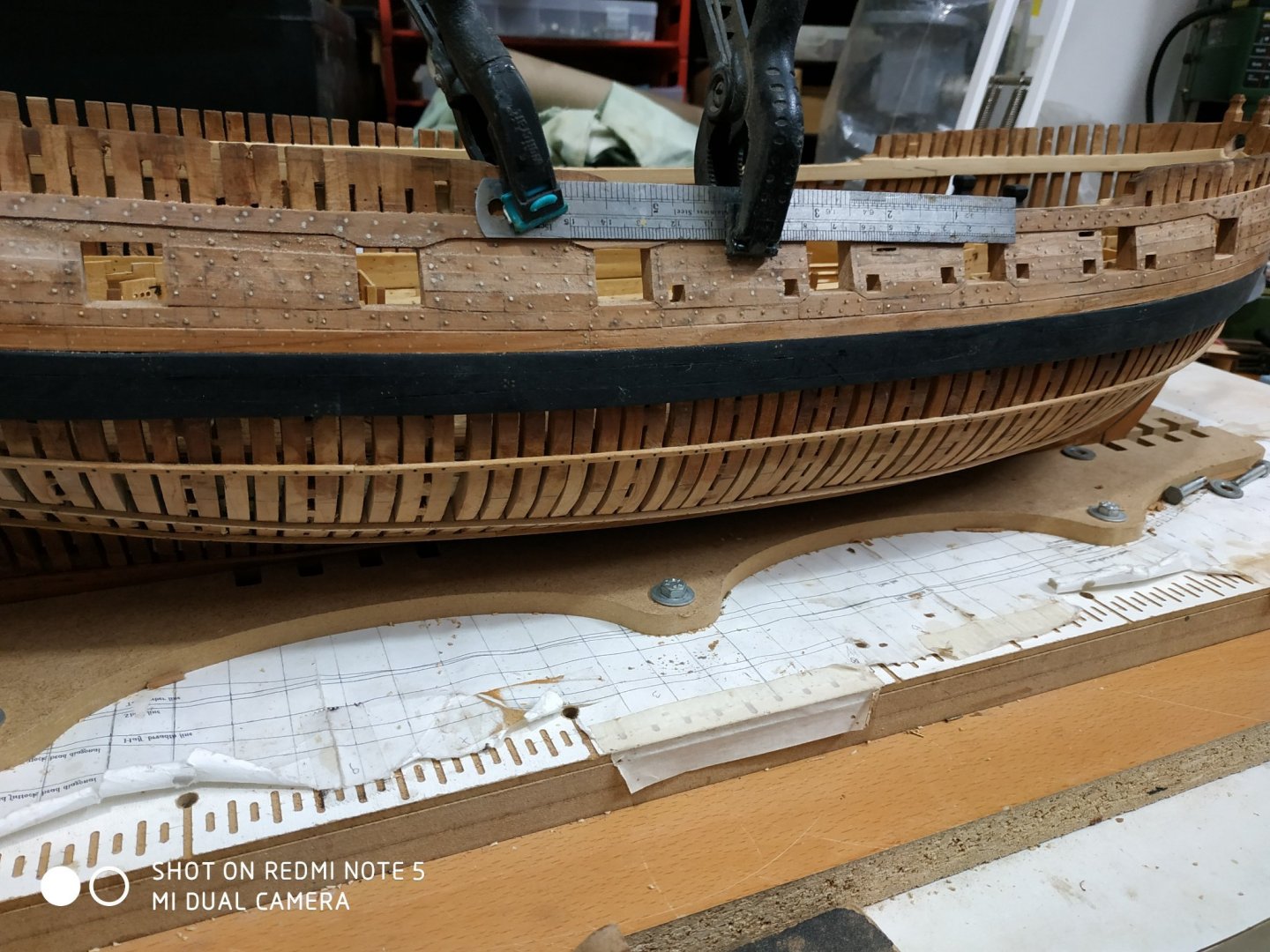
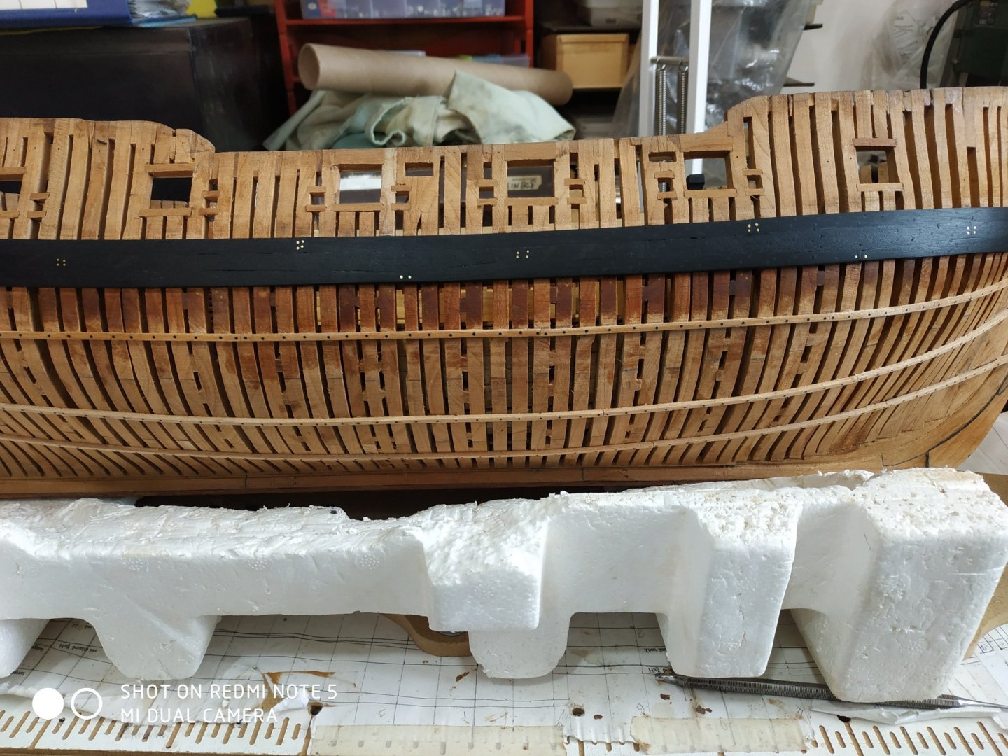
The Main Wale (cont.) The aft sections of the middle and lower strakes are particularly difficult. Acute beveling and sanding are necessary. Checking Goodwin’s book( which says that copper bolts were extensively used),I used copper nails (heads removed) at butt ends. The colour contrast looked jarring, so I “blackened” them.Then after drilling and filling with the treenails, which are barely noticeable,I prefered the shiny ends left after sanding the treenails. The upper and lower edges are slightly chamfered to meet the neighboring strakes. ** About treenails and their appearance- I think that in reality they were barely noticeable (size and colour) but some beautiful models have them very distinctive -black on pale wood and the reverse. I suppose that there is an individual element (as in painting) but if the purpose of the model is to show its features and how it is built, to what extent should it be made “arty”. I am undecided, and I would like my fellow modelers opinions.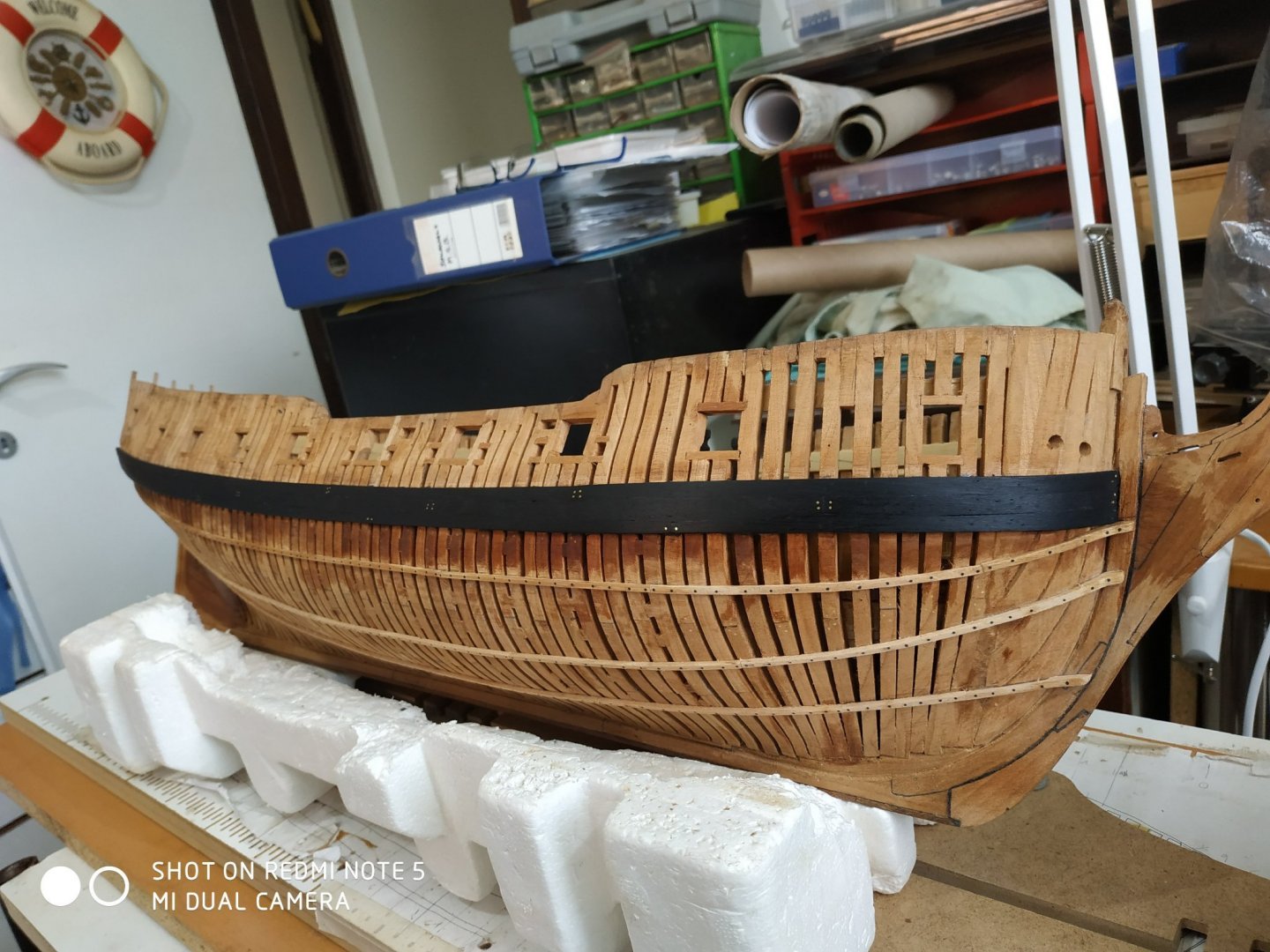
-
Swan-Class Sloop by Stuglo - FINISHED - 1:48
stuglo replied to stuglo's topic in - Build logs for subjects built 1751 - 1800
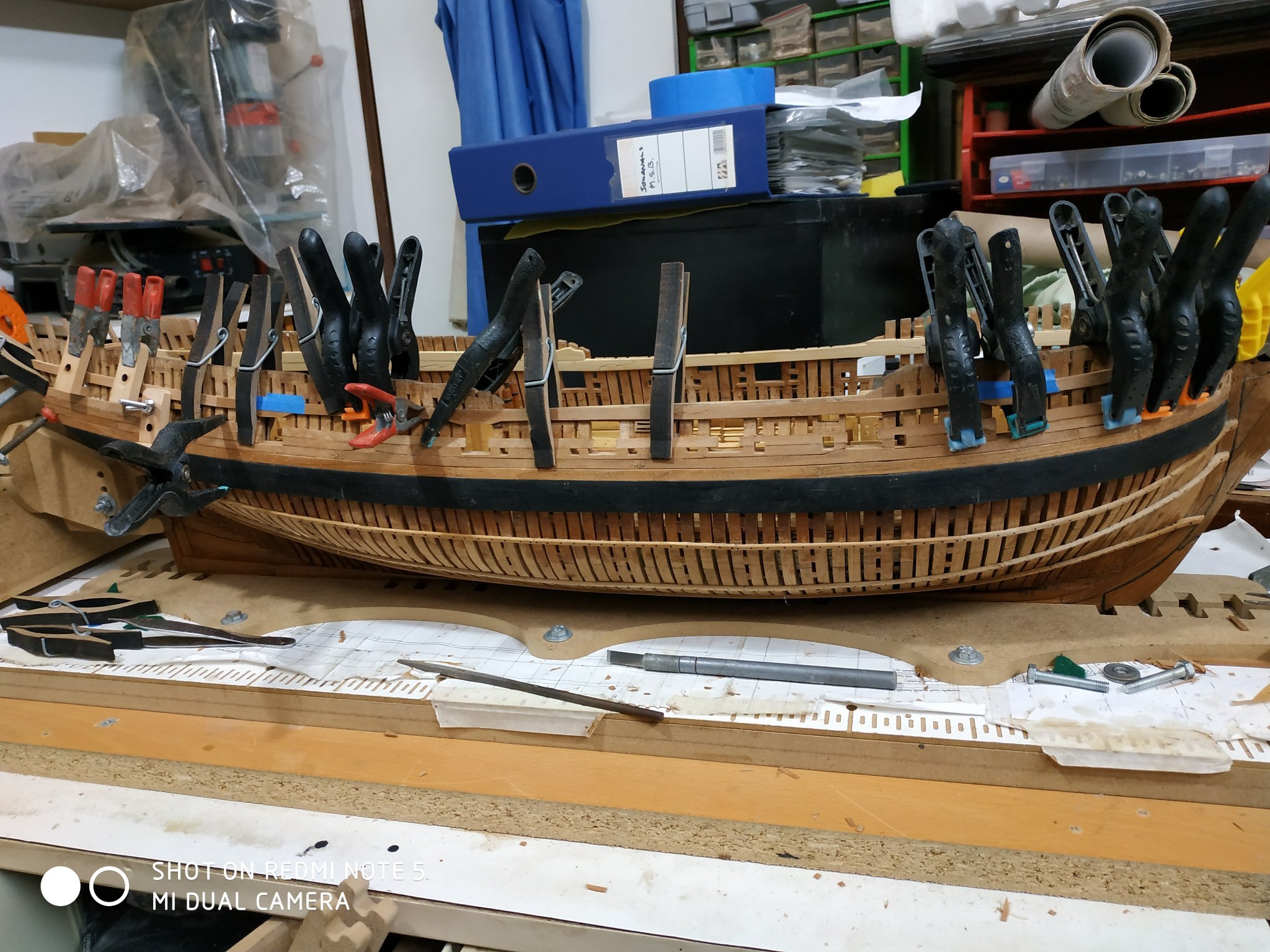
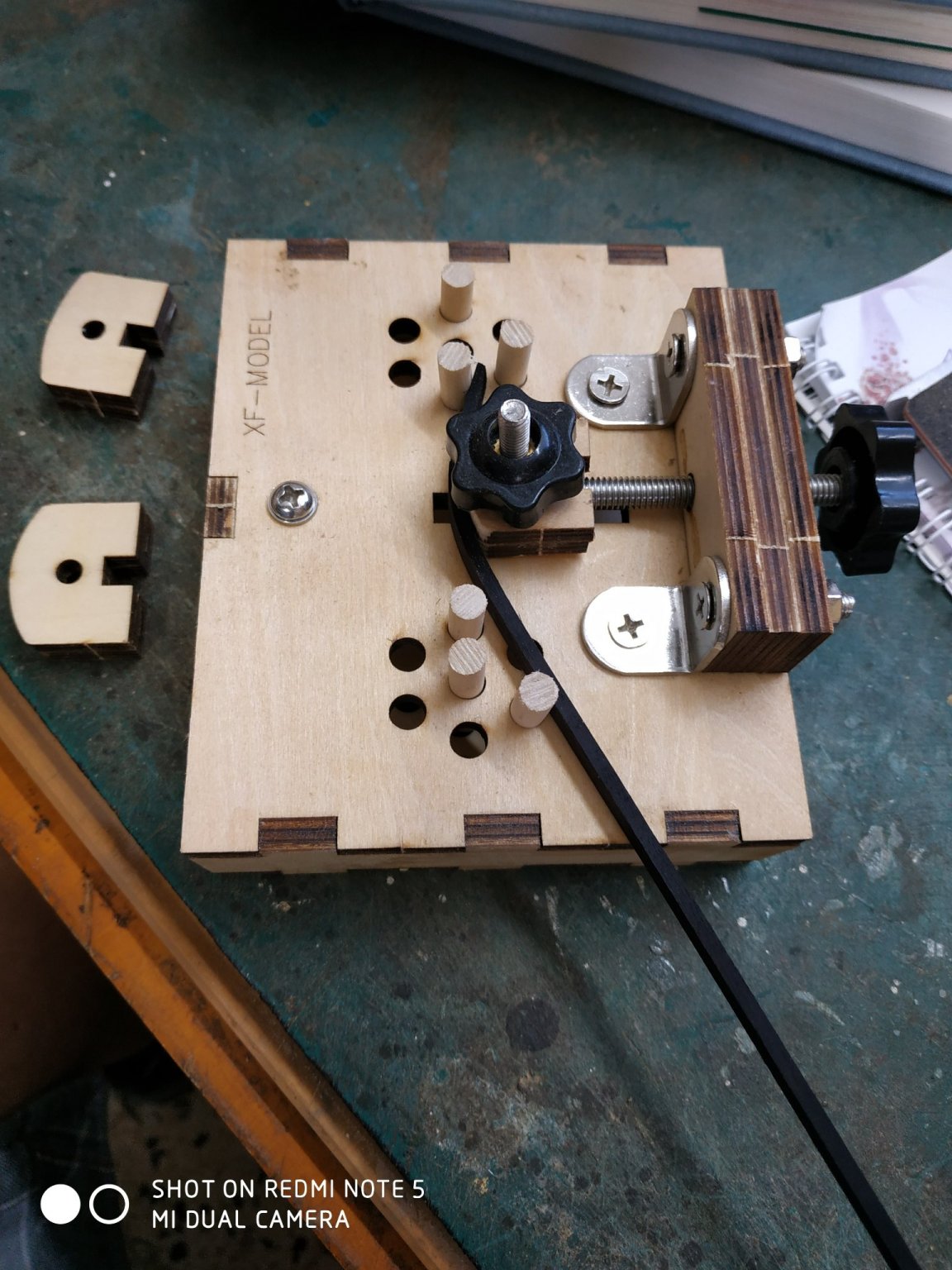
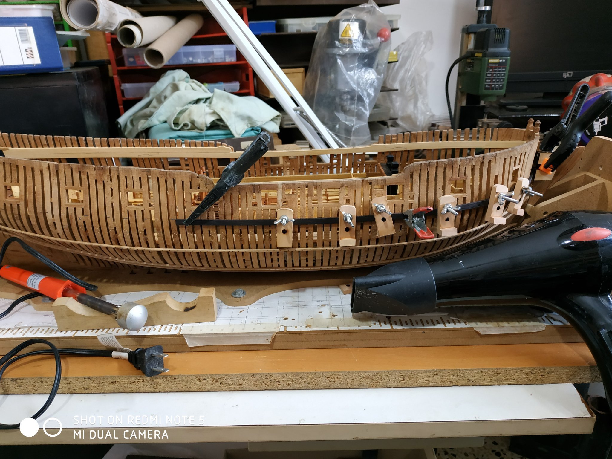
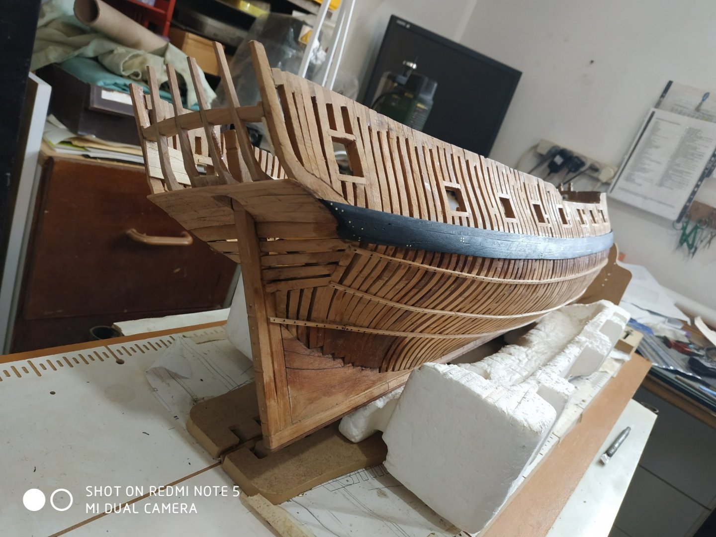
The Main Wale First mark the SHEER line, along the upper side of the ship. Shown on the plan as 2 parallel lines. The heights are marked at each station, from the rabbet of the stem to the stern counter. The 2D plan underestimates the curve and length at the fore part. TFFM gives the ext. Planking expansion, but at 1/96 scale. Copied at /48 professionally. The uppermost plank (#22) is a parallel- the butt joints are given as Hfore,1B aft and 11aft. Blanks sized at4.77x2.4mm.tapered (NOT beveled) to 1.59mm to meet the stem rabbet.. The middle and lower strakes have a Top and Butt design. The wood is blackhornbeam (ordered from Bibigon, Russia)-First time I’ve used it. Very happy but the dust is messy and sticks. I’ve used many suggestions for bending over the years:- lighted matches, hair curling tongs, microwave oven etc, besides the usual hot water (short and long soaks),adapted soldering iron, purchased jigs,clamping to approx. shapes,clamping directly while damp, hair dryer or leaving overnight etc.etc. Really, it depends on what I fancy or recently read, as much as the quality and thickness of the wood, as well as the curve demanded. Here the wood is fairly flexible, moderate thickness;the curves, concave sharpish at stem, mild along length with moderate upward curve towards the stern. Short soak in boiling water, 1st section- the jig and soldering iron The rest, clamping and hair dryer (I haven't needed one for years)

-
Agree- if it works. If not, leave margin around and by trial and error, snip off to fit. Paper is quicker and cheaper if you have a plan to work to; if not, card. ( those given with the local pizzas are perfect.)
-
NRG VIRTUAL WORKSHOP - USING THE TABLE SAW
stuglo replied to kurtvd19's topic in NAUTICAL RESEARCH GUILD - News & Information
If criteria are fulfilled, membership or one time payment, will a recording be available for download at a later date? -
Swan-Class Sloop by Stuglo - FINISHED - 1:48
stuglo replied to stuglo's topic in - Build logs for subjects built 1751 - 1800
The Lower Counter -Planking. A pattern is given for the planks- which are 1.06mm thick The lower edge is fixed to the margin of the Wing Transom. There is some beveling as per side view, but otherwise DO NOT EDGE THEM is emphasised. Also emphasised is to square off the outer ends, avoiding a curve, where it meets the outer counter. The 1st 4 are paired -either side of stem or aperture. The 5th piece stretches across -up against and extending past the knuckle. Unless your model is EXACTLY as the pattern, it won’t fit. (can;t expect to be spoon fed everything). Adapting the formed “blank” was frustrating. I therefore cut the paper pattern along the center, fit to model, sellotaped together and the sticking to a blank, the piece more simply formed. Final shaping of aperture and ends by file, trying to avoid that curve.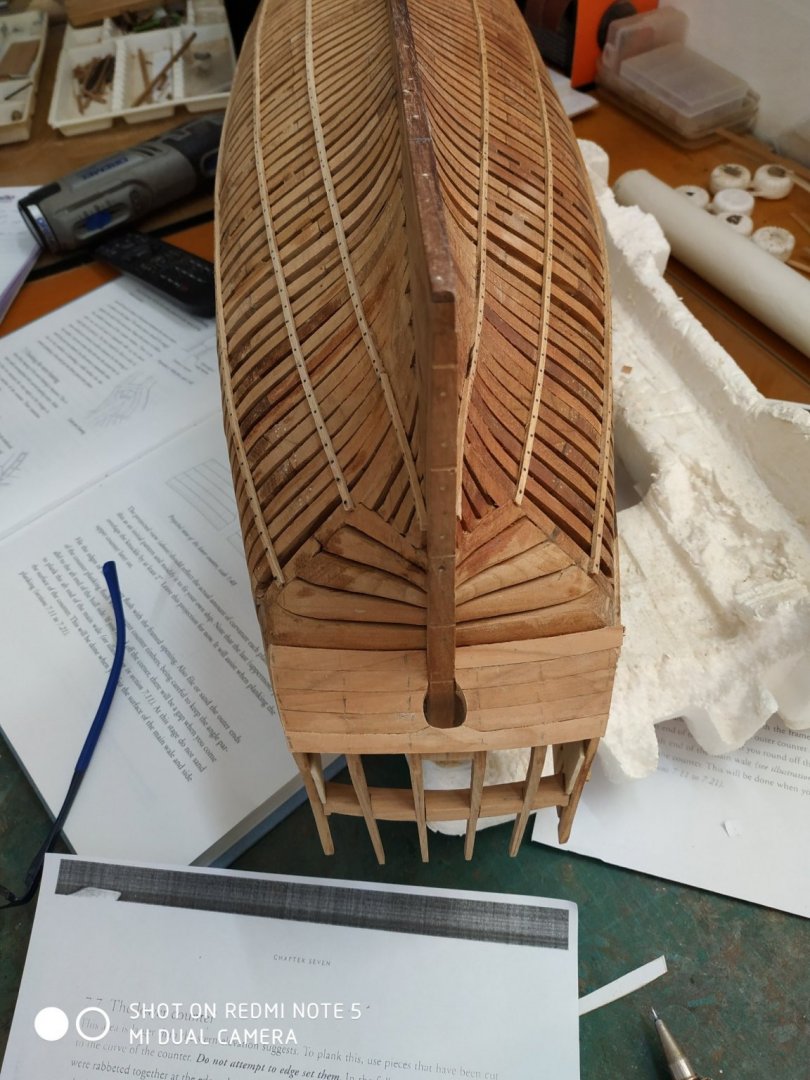


.jpg.165c5a5a7c5fce15d88511afcb262237.jpg)
.jpg.0e5074cff66936552e2381aaddde2d89.jpg)
.jpg.edd377d92db7851474c5e216a174e0ba.jpg)
.jpg.d02b8893175de0bf54d04d8b7a1f6eda.jpg)
.jpg.df167e048bf6c44e01df234c9f9eaa17.jpg)