stuglo
-
Posts
707 -
Joined
-
Last visited
Content Type
Profiles
Forums
Gallery
Events
Everything posted by stuglo
-
Swan-Class Sloop by Stuglo - FINISHED - 1:48
stuglo replied to stuglo's topic in - Build logs for subjects built 1751 - 1800
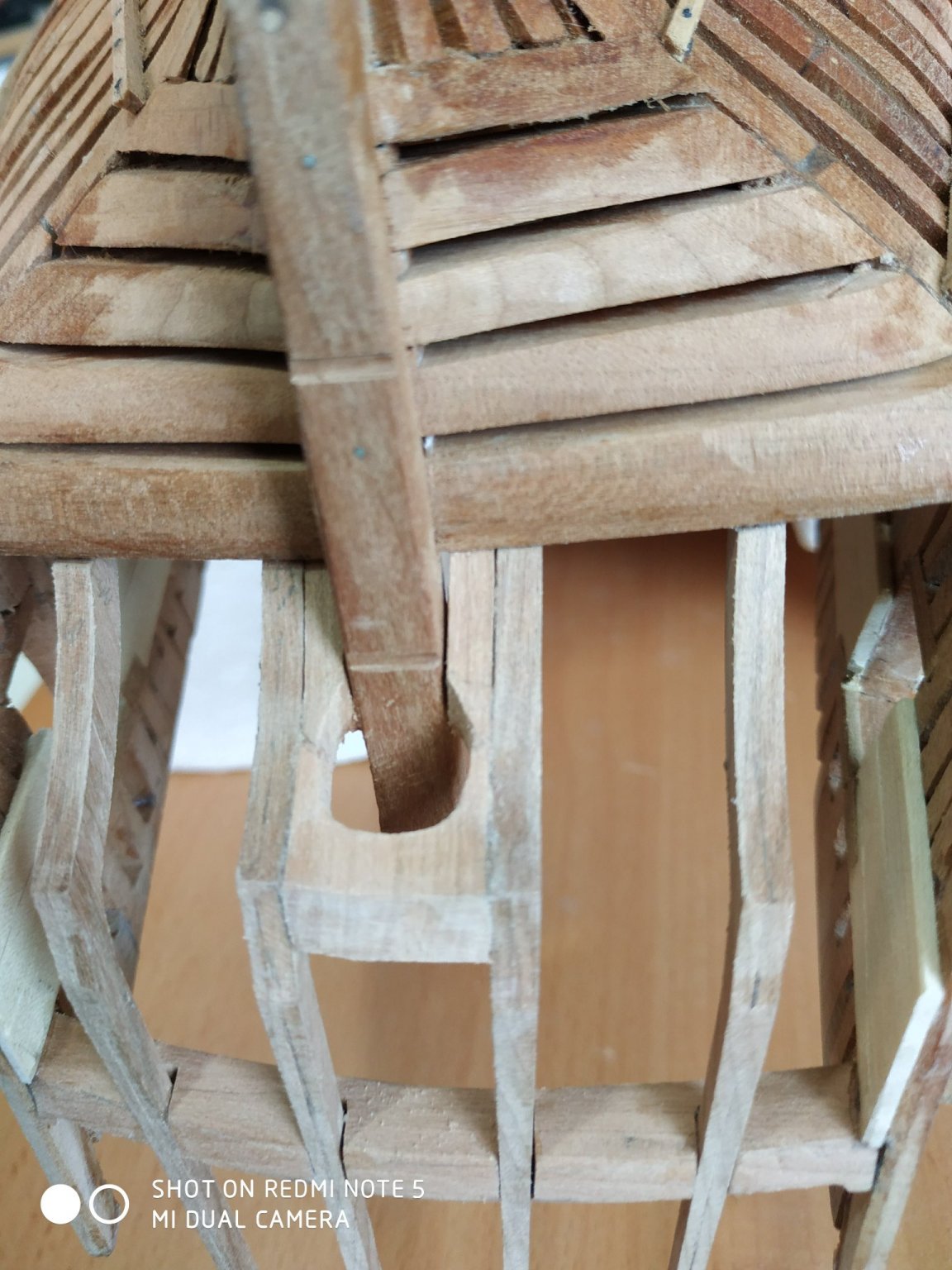
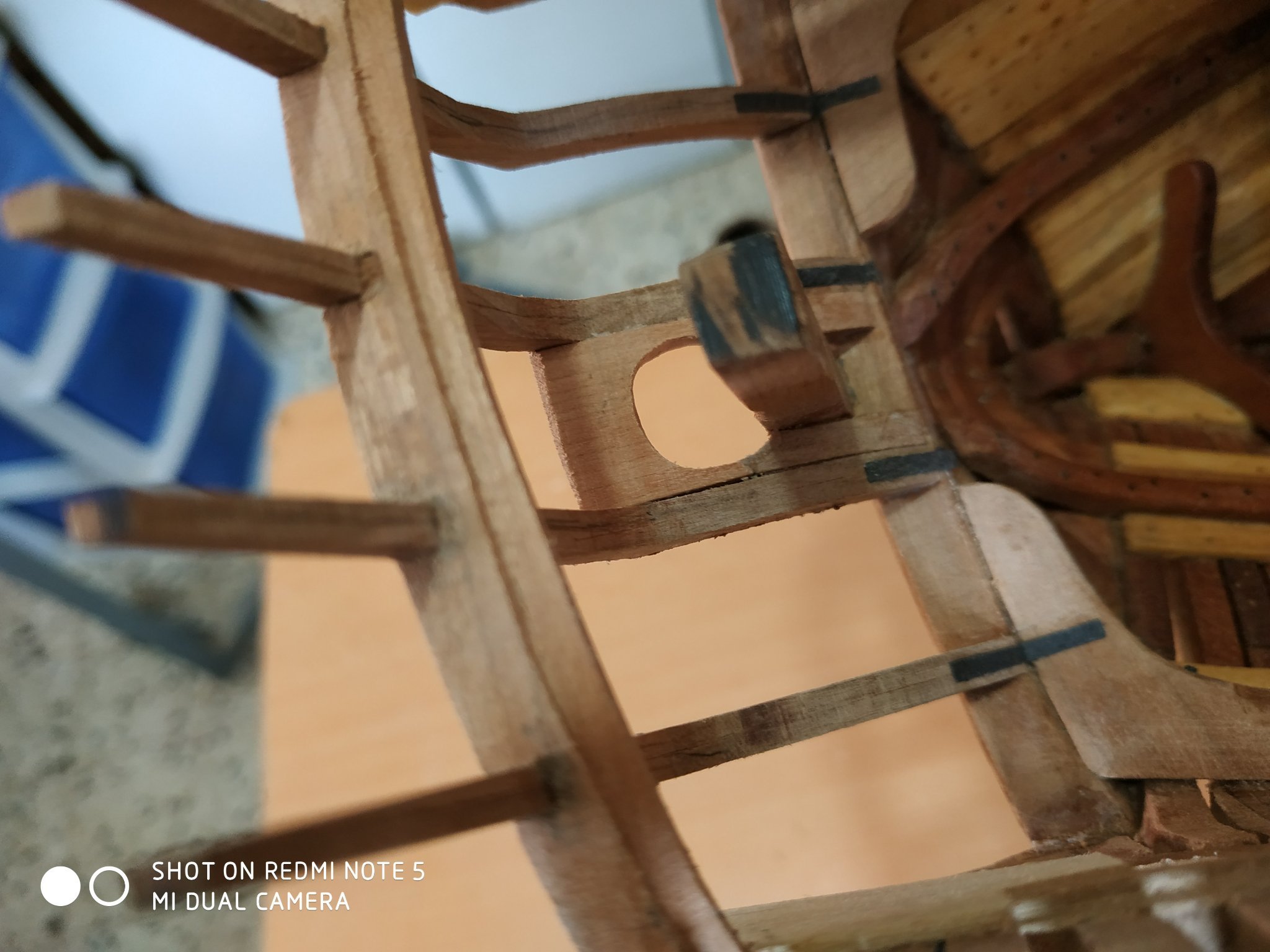
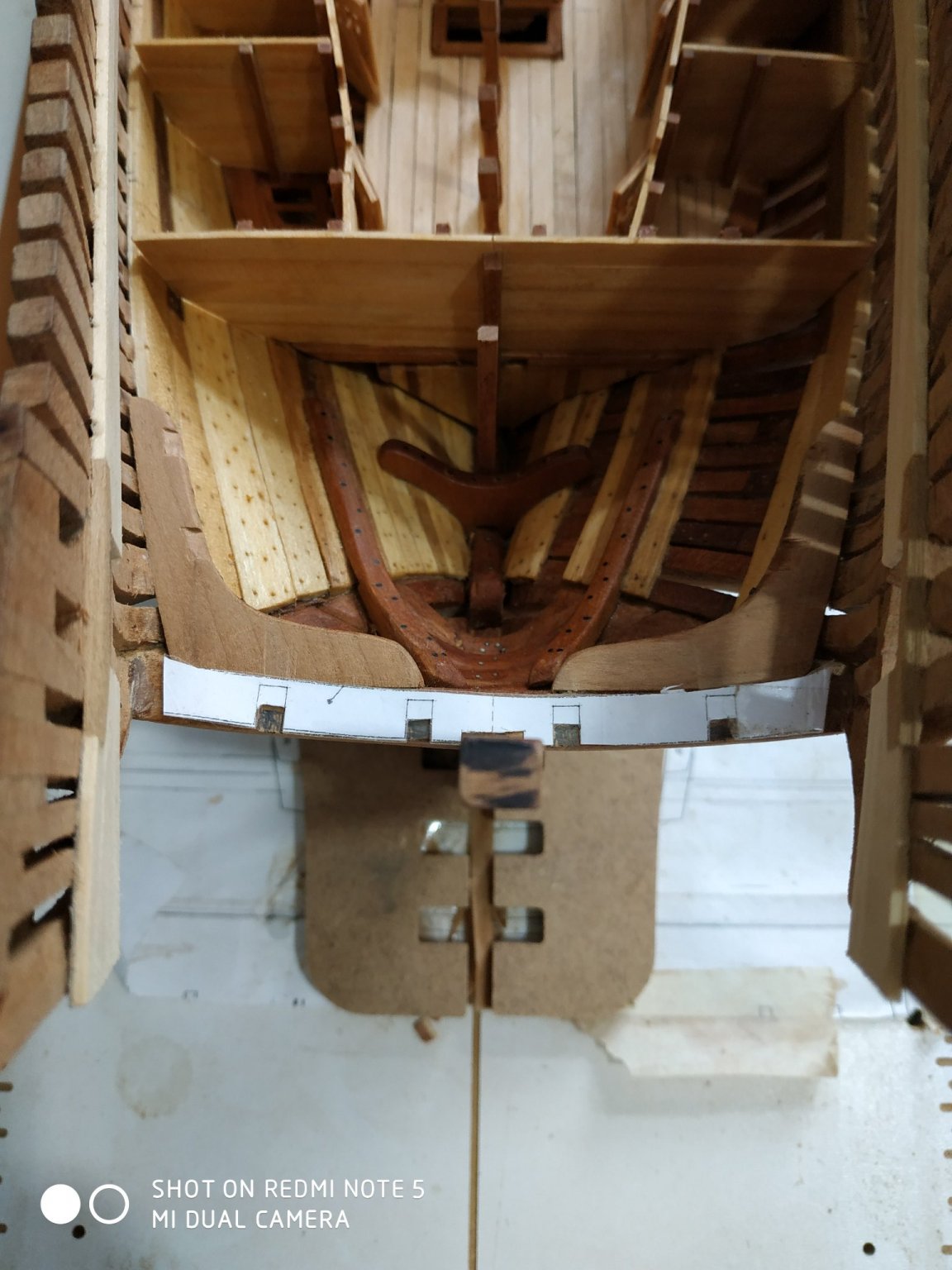
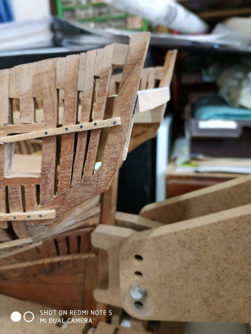
Straps to Counter Timbers. Found my Wing Transom Knees overlong to allow inner straps to be fixed to wing transom. Cur shorter and reshaped. Can't understand “reinforced with iron bolt”- must be hidden by the strap. This strap is 1.86wide and 0.33 thick. Used black paper. The middle counter straps lie on the knee, the inner pair over the fore aspect of the wing transom. The Helm Port. Fills the gap between the inner counter timbers,wrapping the stempost to the fore, and a pear-shaped opening for the fudder head,aft. I wasn’t confident with the 2D plan, so I just used the “hole” part. I made it with a “body” and 2 legs. The width was as measured between the timbers at the 1st knuckle, plu a coupe of mms- the sides are not perfectly parallel/ The hole is slanted to the piece and further allowance for the incline of the rudder. Using the patterns of the inner counters on a blank, thick enough to allow for the curve of whole 1st knuckle to about halfway to the “foot” This curve sits at 22deg to horizontal, and the rudder at about 4 deg.The piece set in the milling at 18deg and the aperture milled out using the pattern. The curves of the inner counter and knuckle sanded and the aft curve aft of knuckle, similarly formed. This is dry fitted and the “legs” shaped similarly to match the forepart of the inner counter timbers incl. The feet. These last I gave a small bevel of 2deg. The parts matched to allow the legs to extend slightly aft of the sternpost.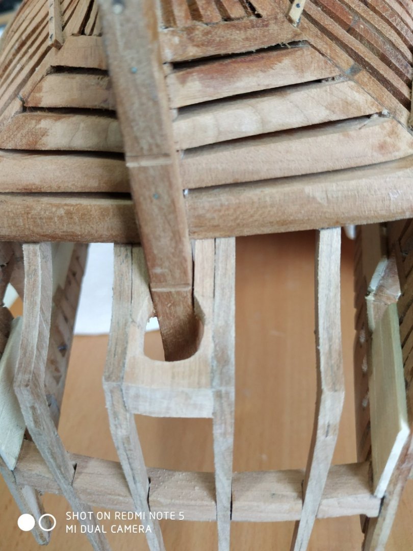

-
Swan-Class Sloop by Stuglo - FINISHED - 1:48
stuglo replied to stuglo's topic in - Build logs for subjects built 1751 - 1800
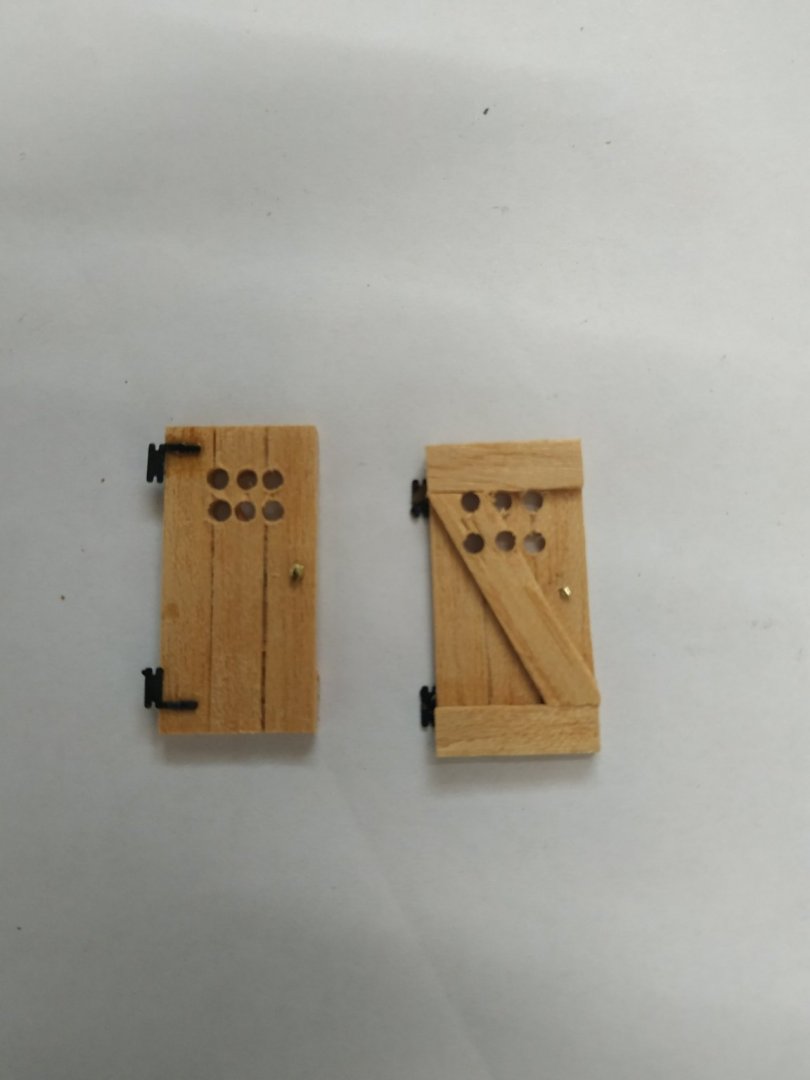
Doors Reworked-I hope for the better. Seriously, remarks, critical or other, welcomed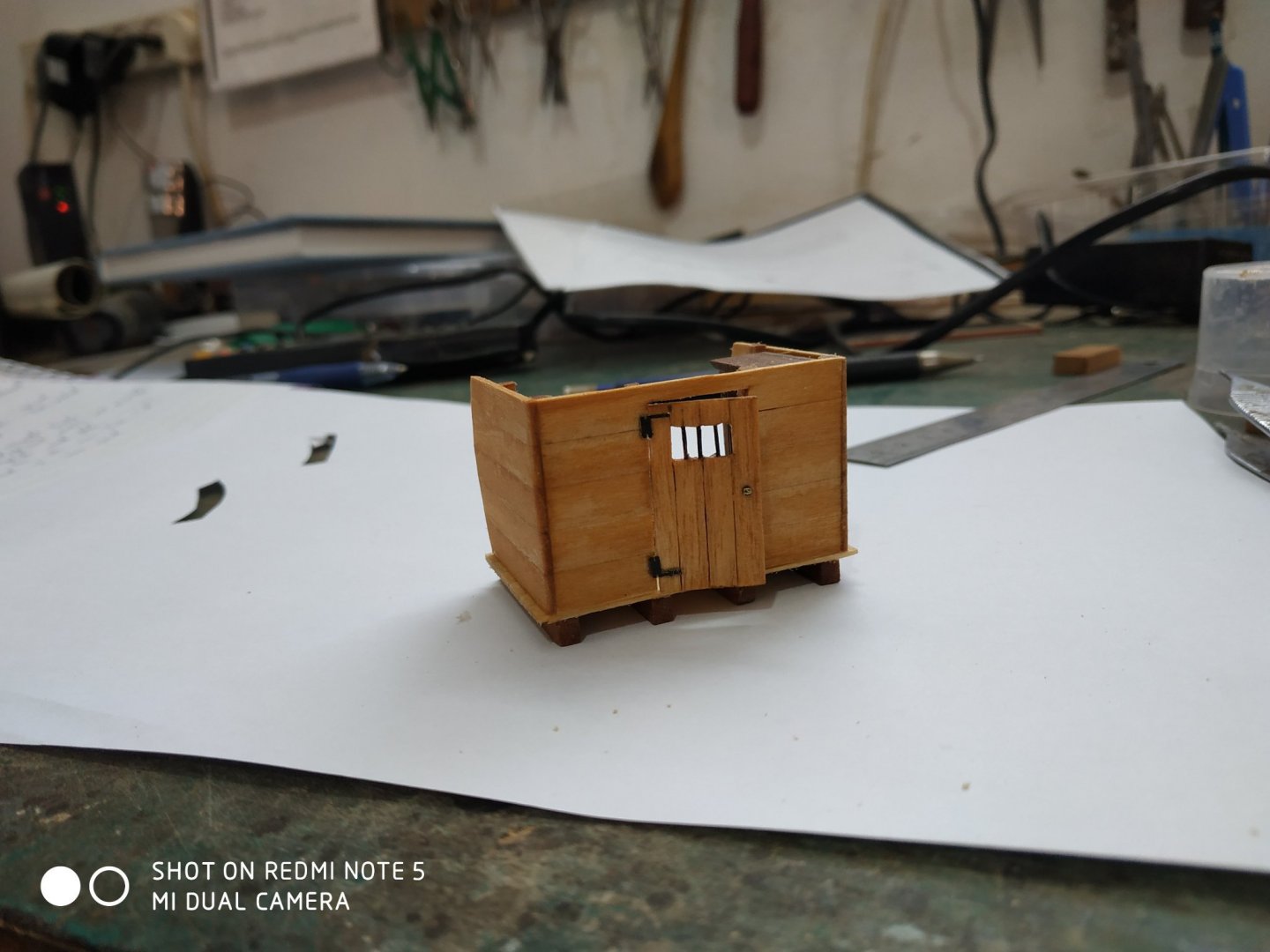

-
Swan-Class Sloop by Stuglo - FINISHED - 1:48
stuglo replied to stuglo's topic in - Build logs for subjects built 1751 - 1800
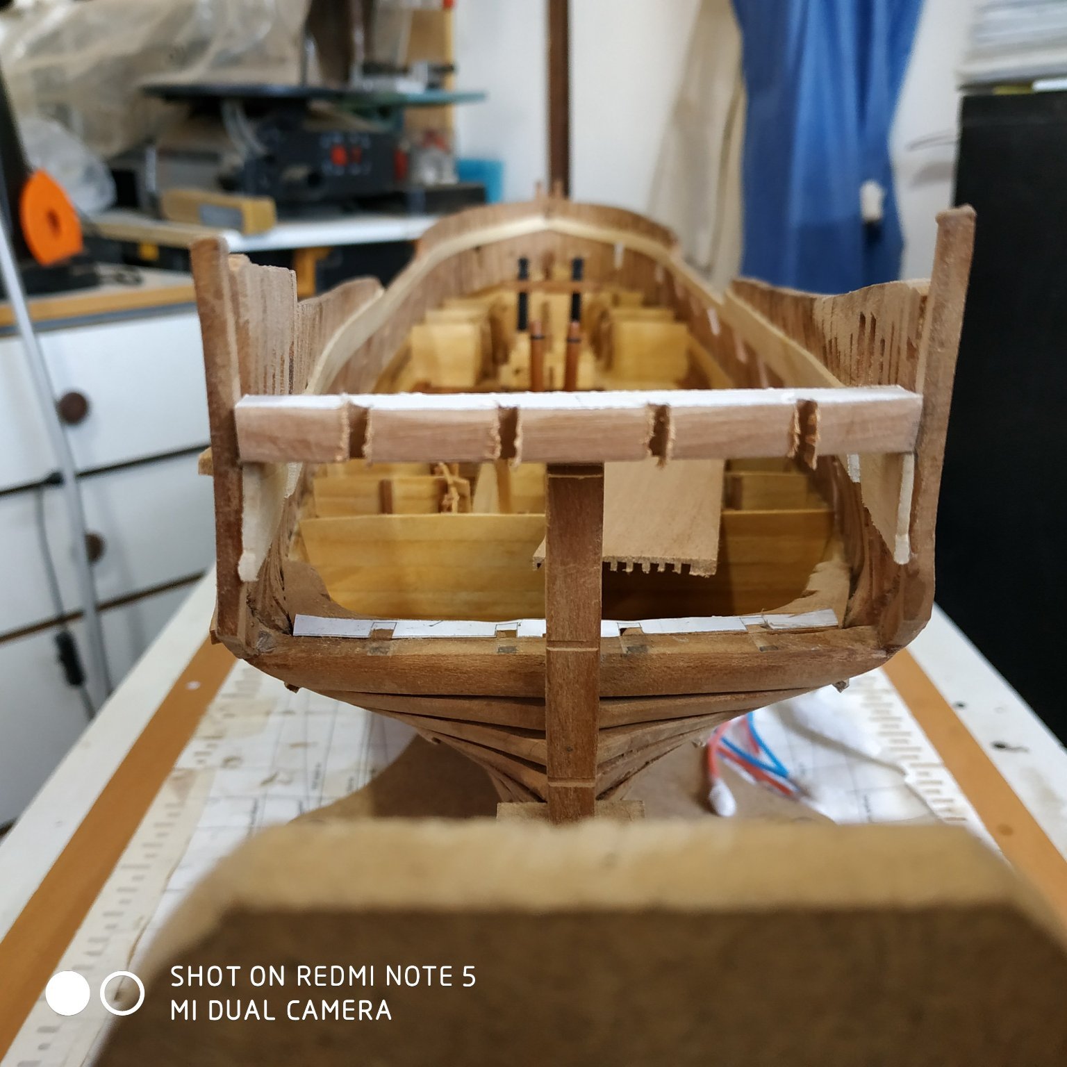
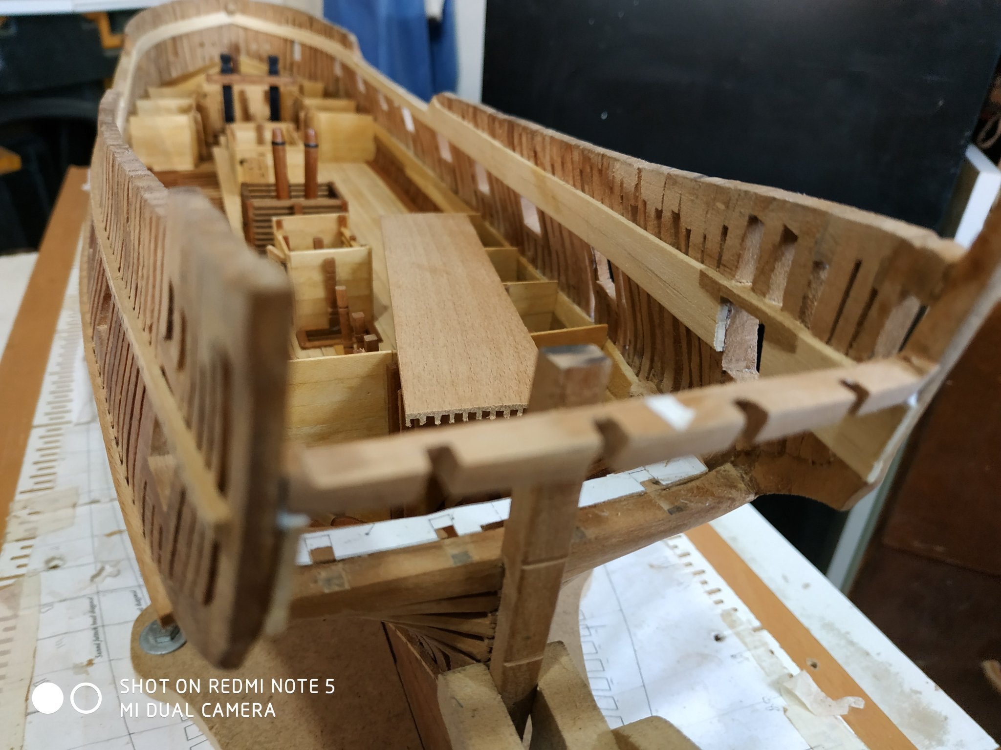
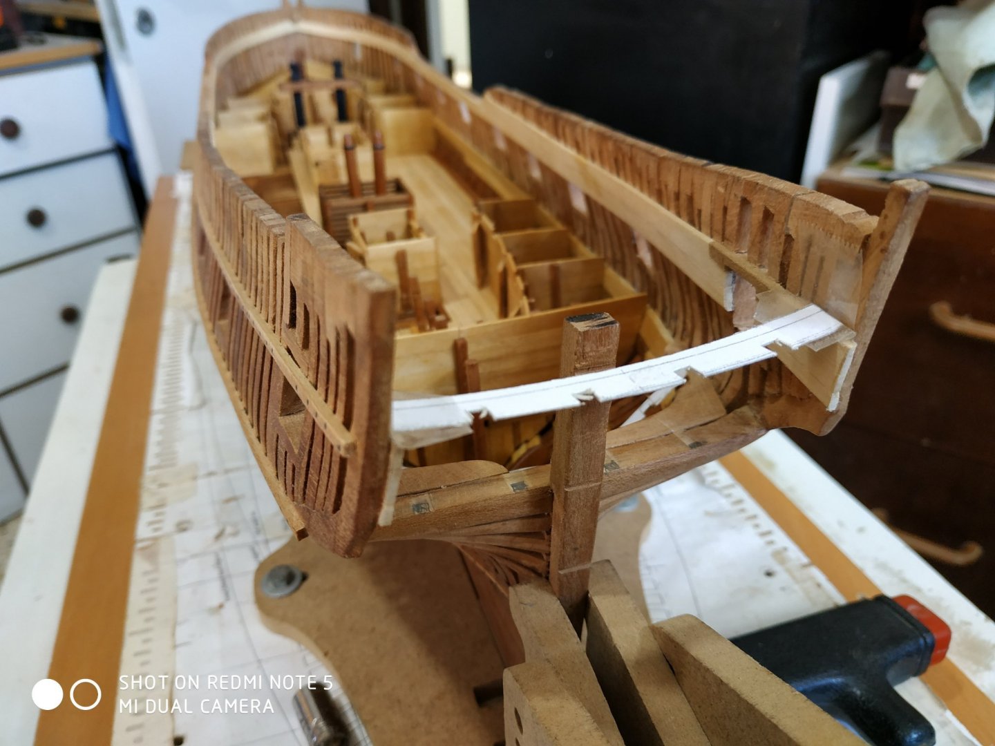
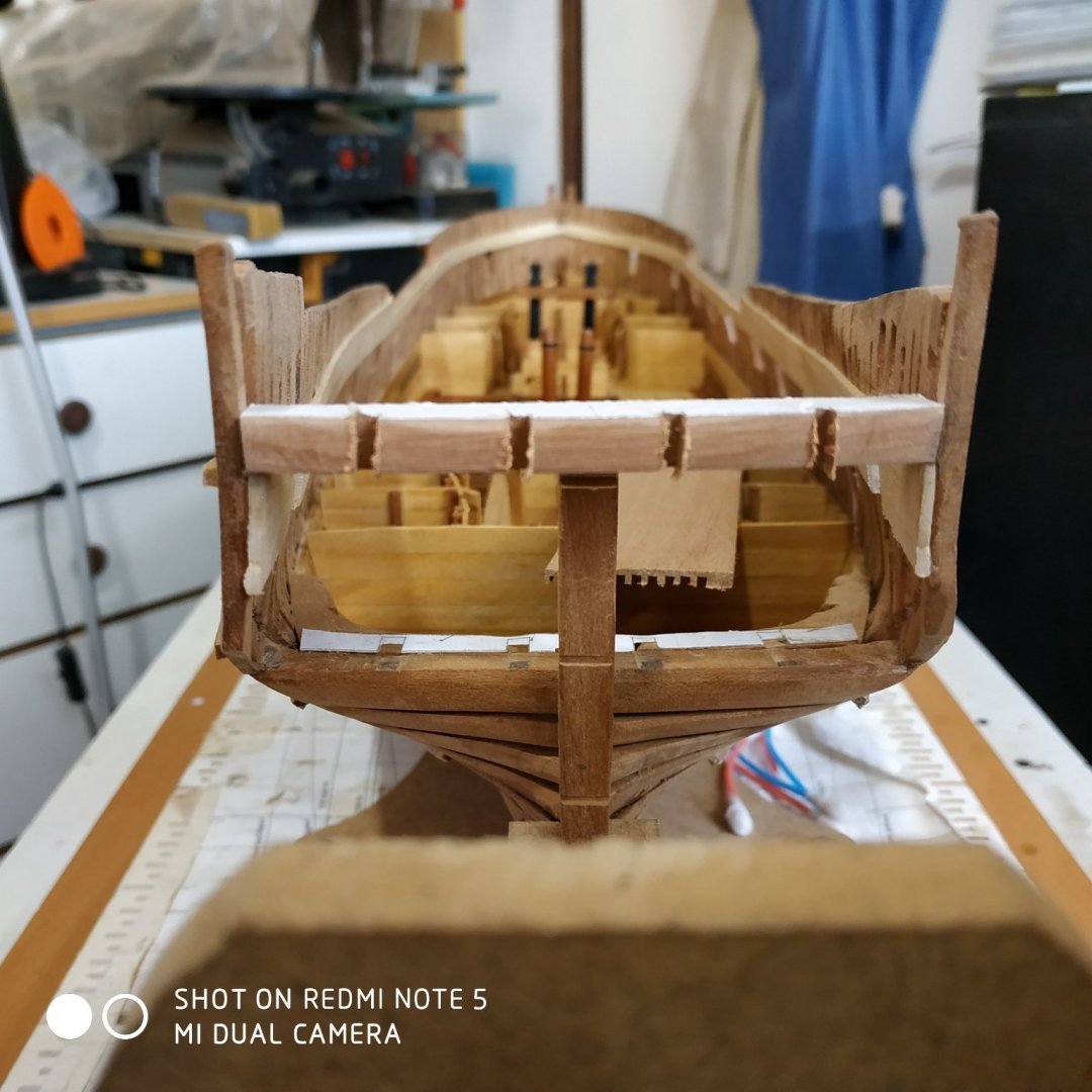
Quarter Deck Transom. This is one of the most complicated pieces so far. Basically, the part stabilizes the counter timbers and acts as the aft most quarter deck beam. It sits on an upward sloping clamp, curves in both vertical and horizontal planes, the aft curve bevelled to match the angle of the counter timbers. The notches or slots for the counter timbers, must allow for the side taper and the angle as they pass through. There is also a rabbet on the fore-upper surface, and extra thickness to be left on outer ends for later use as waterways. Think 3D and double it. With its function as a beam, it has a thickness of 2.9mm Added to this is the thickness of the planks at 1.33mm Total thickness 4.23mm. It is also rounded up (full width beam 3.25mm), so the suggested blank is 6.36mm thick. First cut width to fit and ensure symmetry-keep midline marked. Athwartship curves sanded and by placing piece in position, the aft bevel can be taken directly from the line of the outer counter timbers. 4 slots as marked milled and by trial and error, enlarged to allow the angles and tapers of the other counter timbers. Result- TOTAL BALLS UP !!. This needs thinking out properly. Early night, wake up at 2.30, clear headed and inspired. Measure angles of the timbers as they pass through the transom vertically (Z axis)6deg and 1.25deg Make a new blank overly wide. Again bevel the aft curve as before. Match this curve to the fore surface- now the piece with sit on the milling table so that when the milling bit moves horizontally, it will cut the wood at the angle matching the counter timbers Adjust the blank so the Y axis movement matches the 6deg(middle) and 1.5deg (inner) Mill bit slightly less than width of counter timbers at level of transom-similarly depth of notch. While fixed in vise, slightly enlarge slots to fit timbers. Revise fore curve to match aft (but without the bevel) Measure rounding up for this length of beam from the pattern in TFFM (I have assumed as with other beams, that this is for a full length and thus the camber is constant) With this width, round up 2.2mm Leave outer margin of 3or so mm for waterway Rabbet (for deck planking)1.9 wide and 1.33 deep I made the mistake of carving the rabbet before the correction for the round up. This was rectified with greater difficulty due to the double curve. The alternative, thinning the piece and adding an inner strip, would bring the lower aspect to be removed, too near the notches for the counters. Fix the quarter transom ensuring it is centred. Locate the feet of counter timbers on their place on the wing transom and place in respective notch and fix . (One edge will stand slightly proud because I postponed the suggested bevel when the timbers were first made). Eyeball from sides , aft and above to ensure alignments ok. Fix, cross fingers and leave the glue to do its job Phew !!! This was a build I was Quarter Deck Transom. This is one of the most complicated pieces so far. Basically, the part stabilizes the counter timbers and acts as the aft most quarter deck beam. It sits on an upward sloping clamp, curves in both vertical and horizontal planes, the aft curve bevelled to match the angle of the counter timbers. The notches or slots for the counter timbers, must allow for the side taper and the angle as they pass through. There is also a rabbet on the fore-upper surface, and extra thickness to be left on outer ends for later use as waterways. Think 3D and double it. With its function as a beam, it has a thickness of 2.9mm Added to this is the thickness of the planks at 1.33mm Total thickness 4.23mm. It is also rounded up (full width beam 3.25mm), so the suggested blank is 6.36mm thick. First cut width to fit and ensure symmetry-keep midline marked. Athwartships curves sanded and by placing piece in position, the aft bevel can be taken directly from the line of the outer counter timbers. 4 slots as marked milled and by trial and error, enlarged to allow the angles and tapers of the other counter timbers. Result- TOTAL BALLS UP !!. This needs thinking out properly. Early night, wake up at 2.30, clear headed and inspired. Measure angles of the timbers as they pass through the transom vertically (Z axis)6deg and 1.25deg Make a new blank overly wide. Again bevel the aft curve as before. Match this curve to the fore surface- now the piece with sit on the milling table so that when the milling bit moves horizontally, it will cut the wood at the angle matching the counter timbers Adjust the blank so the Y axis movement matches the 6deg(middle) and 1.5deg (inner) Mill bit slightly less than width of counter timbers at level of transom-similarly depth of notch. While fixed in vise, slightly enlarge slots to fit timbers. Revise fore curve to match aft (but without the bevel) Measure rounding up for this length of beam from the pattern in TFFM (I have assumed as with other beams, that this is for a full length and thus the camber is constant) With this width, round up 2.2mm Leave outer margin of 3or so mm for waterway Rabbet (for deck planking)1.9 wide and 1.33 deep I made the mistake of carving the rabbet before the correction for the round up.This was rectified with greater difficulty due to the double curve. The alternative, thinning the piece and adding an inner strip, would bring the lower aspect to be removed, too near the notches for the counters. Fix the quarter transom ensuring it is centred. Locate the feet of counter timbers on their place on the wing transom and place in respective notch and fix . (One edge will stand slightly proud because I postponed the suggested bevel when the timbers were first made). Eyeball from sides , aft and above to ensure alignments ok. Fix, cross fingers and leave the glue to do its job Phew !!! This was a build I was dreading. Taking it in stages and learning to adapt the blank to the limitations of my tools and ability seems to have paid off.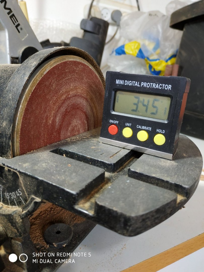


-
Swan-Class Sloop by Stuglo - FINISHED - 1:48
stuglo replied to stuglo's topic in - Build logs for subjects built 1751 - 1800
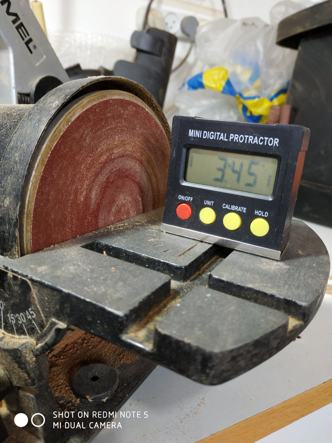
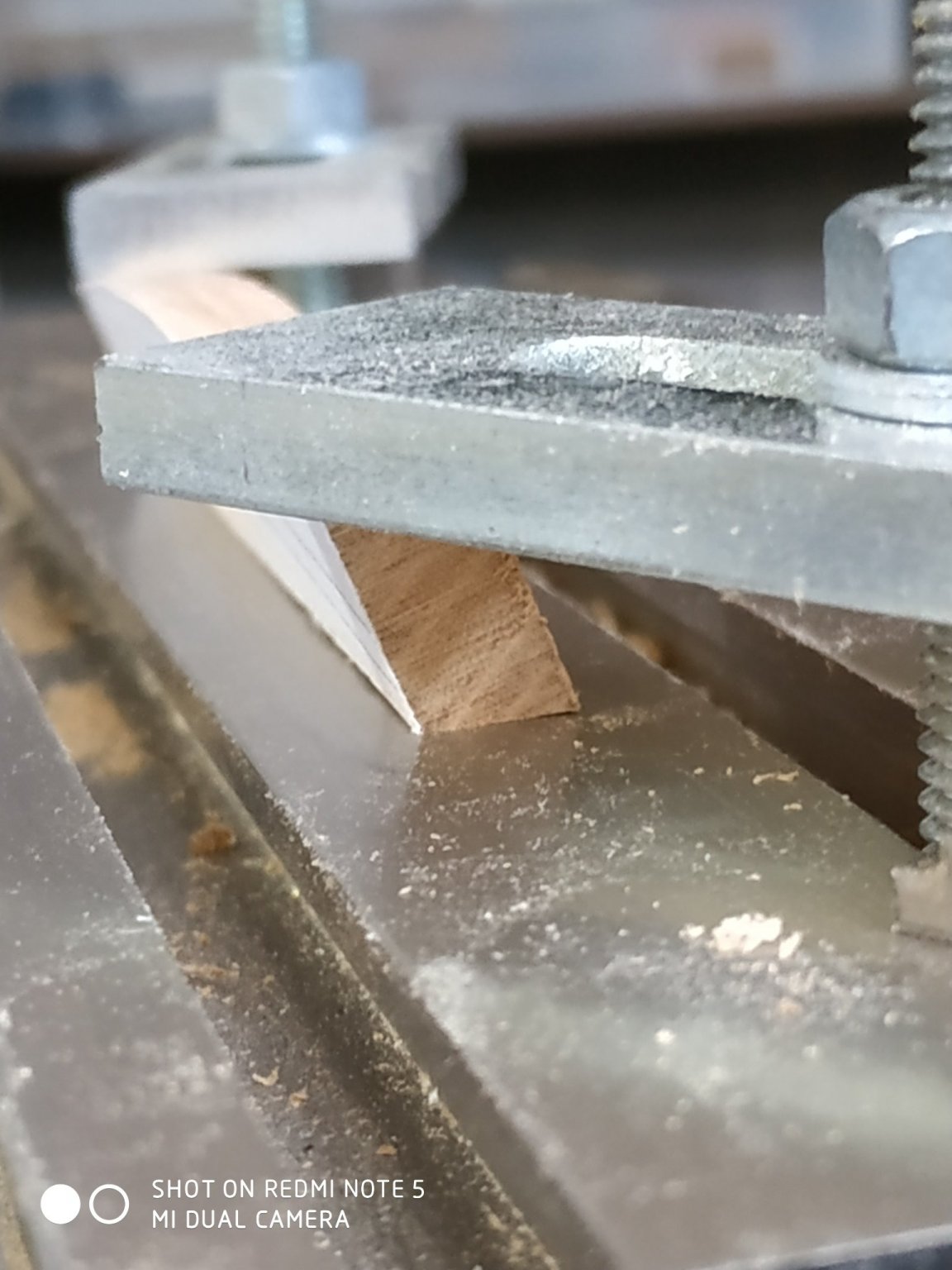
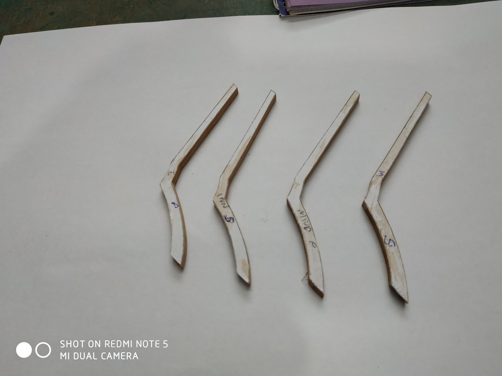
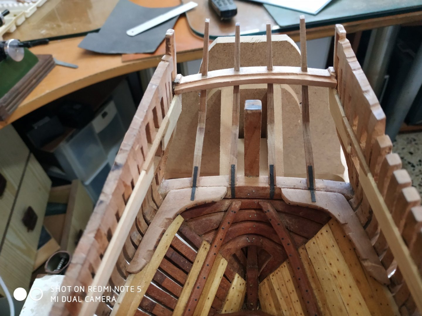
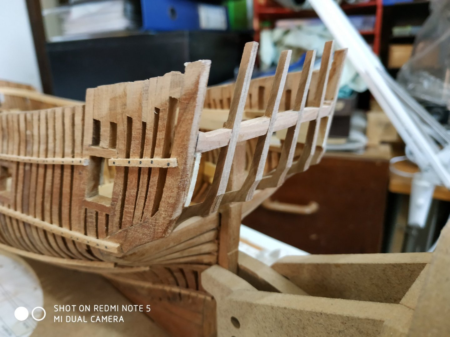
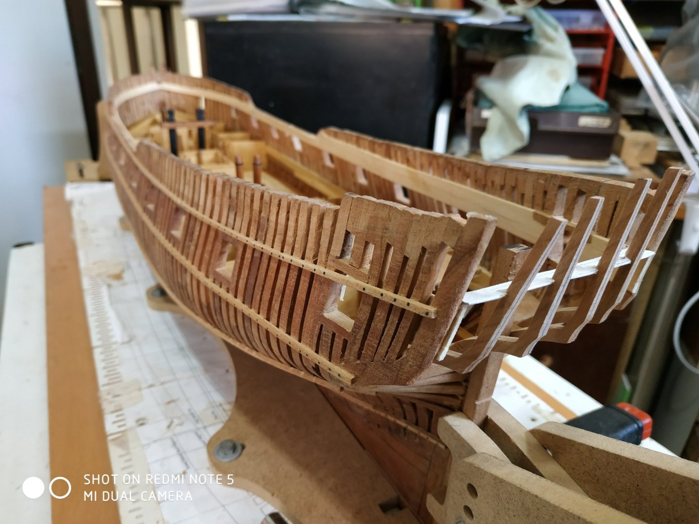
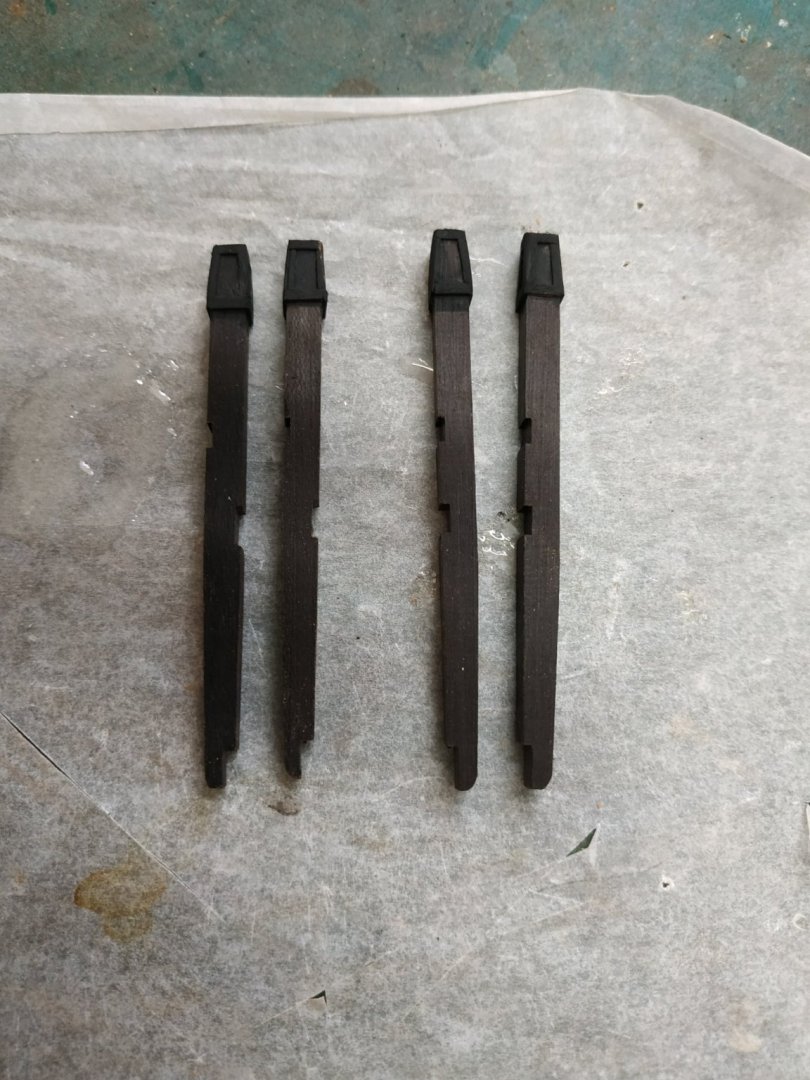
No surprise, decided to continue onto vol 2 TFFM. Semi scratch kits no substitute at present for the hardcore, mainline stuff. Inner Counter Timbers These are for equidistant timbers (suggested separation,16.43mm) between the outer counter timbers (the aftermost part of the ship) Double check angles and distancing (ref. 2.21 TFFM) because these have been knocked about and repaired twice. Using the markout pattern, mark the position of the feet on the wing transom. I left this pattern slightly forward on the transom knees, to aid later sighting. Using stock 3.71mm. I decided to forgo the pleasure of making a scarf joint and sticking the patterns given on the blanks, cut the shape. Mark each piece as there is a difference. The “soles” of the feet are bevelled- middle 10deg and inner 3.5deg- so the “legs”are “knock-kneed”. The sides are now tapered from a top of 2.12mm to near bottom using a sanding board. I checked alignment with a card cut out of the quarterdeck transom-they seem ok.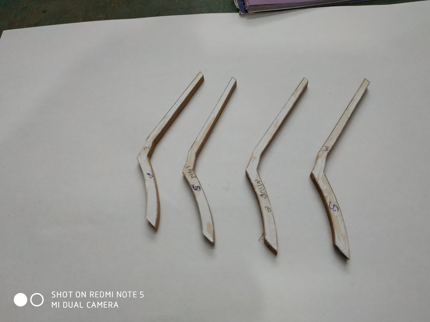
-
Swan-Class Sloop by Stuglo - FINISHED - 1:48
stuglo replied to stuglo's topic in - Build logs for subjects built 1751 - 1800
I do intend to plank one side, so will have most of difficulty.( other or second side usually easier) Anyway, looking at beginning of vol 2 (revised) and the stern structure build frightens me !! -
Swan-Class Sloop by Stuglo - FINISHED - 1:48
stuglo replied to stuglo's topic in - Build logs for subjects built 1751 - 1800
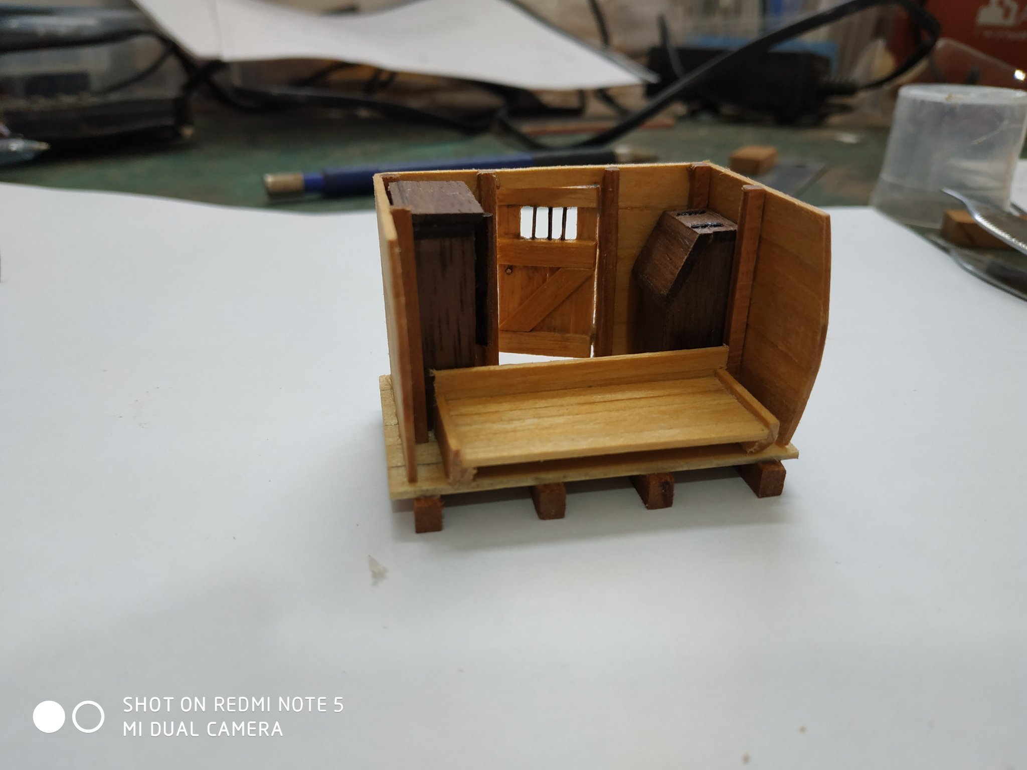
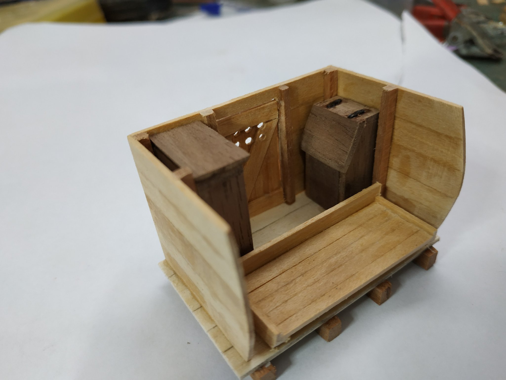
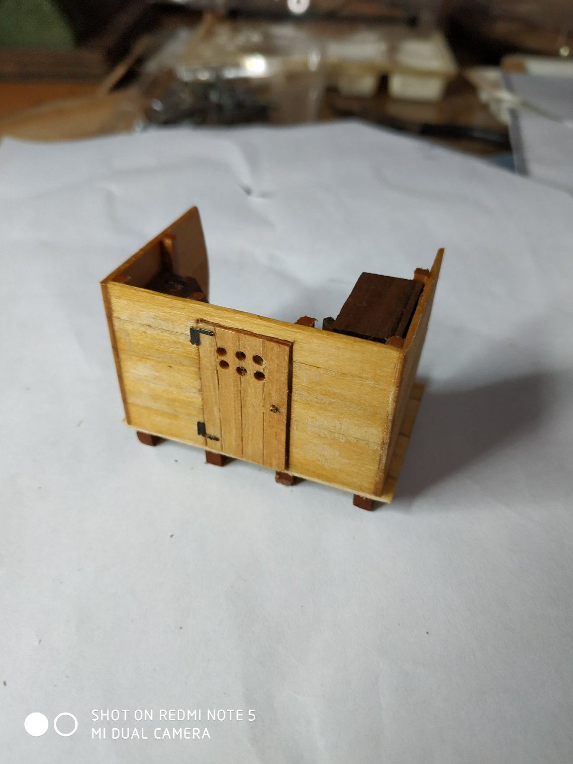
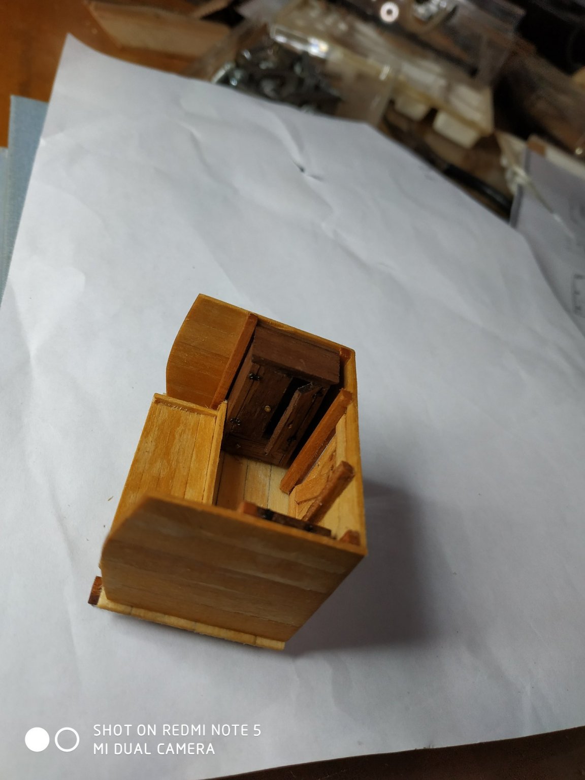
Lower Deck Structures, cont. While beams in place check alignment and centre of each Doors -simplified. Thinner vertical planks and reinforcing “Z” on the inside. Holes, not fancy louvre or bars (I remember such things as a child on outside loos) Height 28 mm but some variety in width. As almost all will be hidden despite leaving off some planks, I will not fit cabin furniture but rather made a set to display alongside the oven, outside of the ship. This finishes t5he 1st vol of TFFM, ? continue now or have a break to build something else. Watch this space !!!


-
Swan-Class Sloop by Stuglo - FINISHED - 1:48
stuglo replied to stuglo's topic in - Build logs for subjects built 1751 - 1800
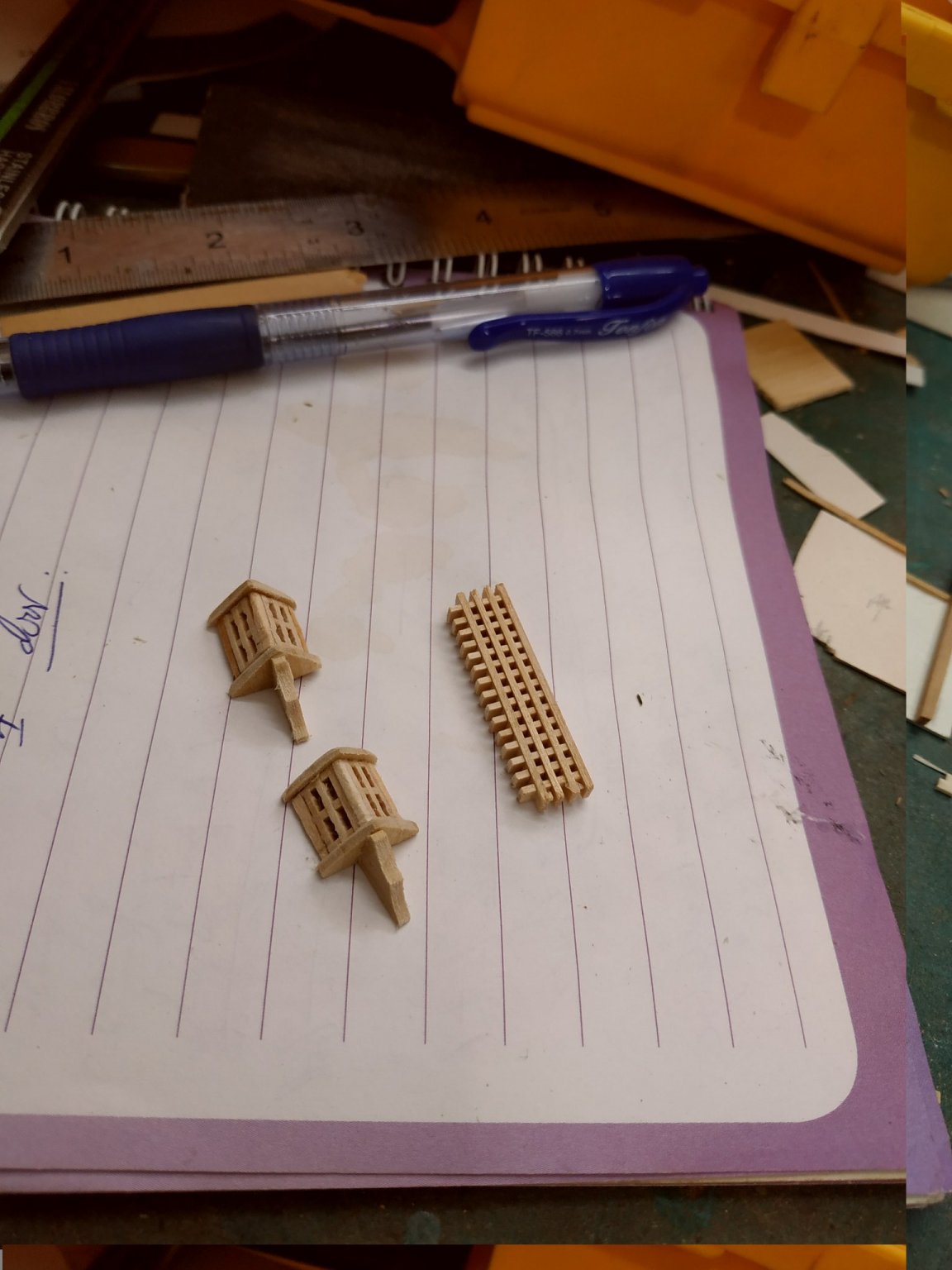
Lanterns. On either side of the 1st fore aft bulkhead. Tried a different method this time ( TFFM has a short tutorial but beyond my patience at present) Anyway, I found some leftover bits of gratings from an old kit (? scale 75) By drilling out cross pieces either side of a vertical, was left with a piece lookin like a window, and at the size required-11.5X5.8mm. Thinned them down, joined into a “V” and added floor, roof and support bracket. Better than lat effort, and will be hidden anyway.

-
Swan-Class Sloop by Stuglo - FINISHED - 1:48
stuglo replied to stuglo's topic in - Build logs for subjects built 1751 - 1800
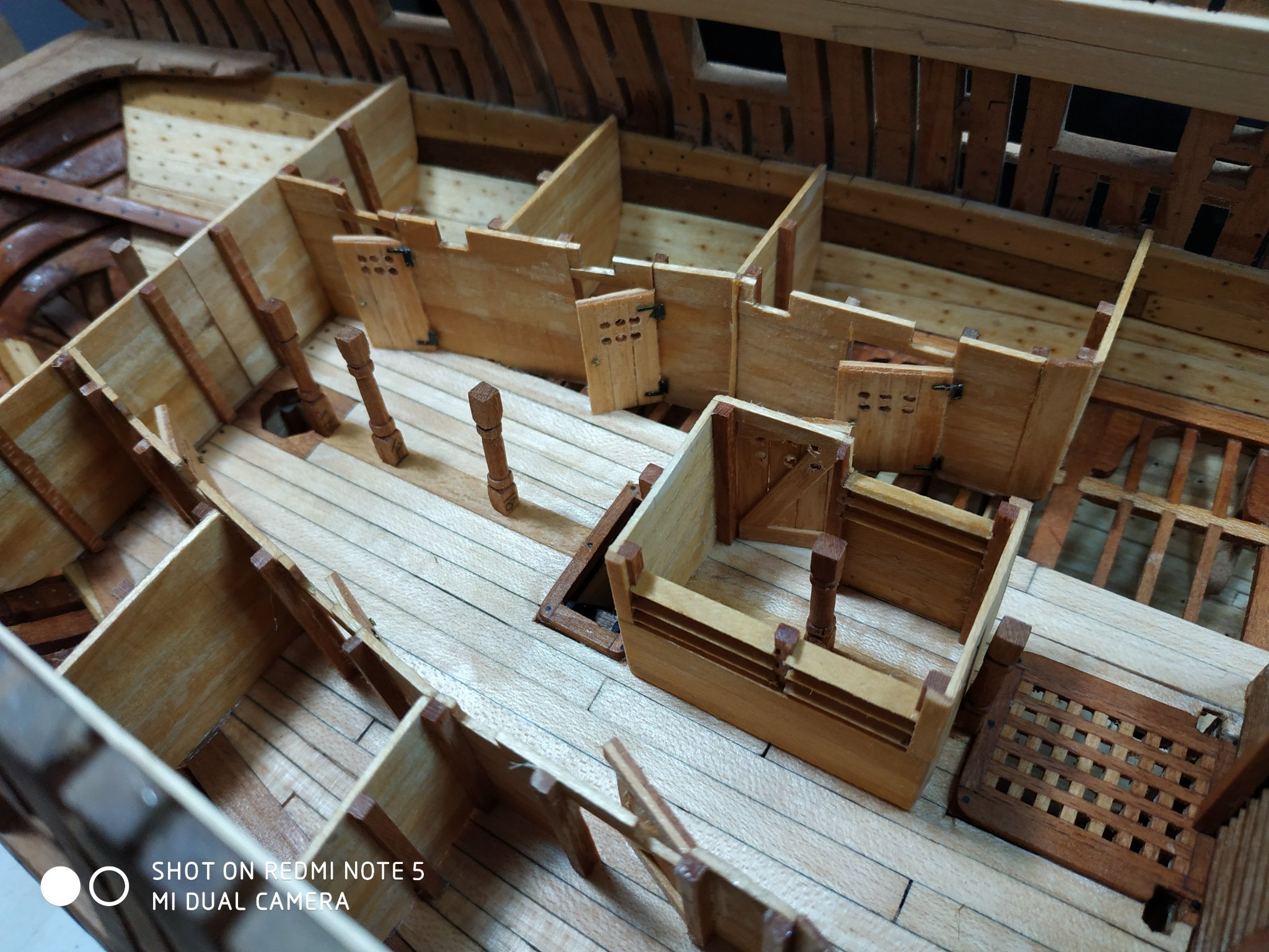
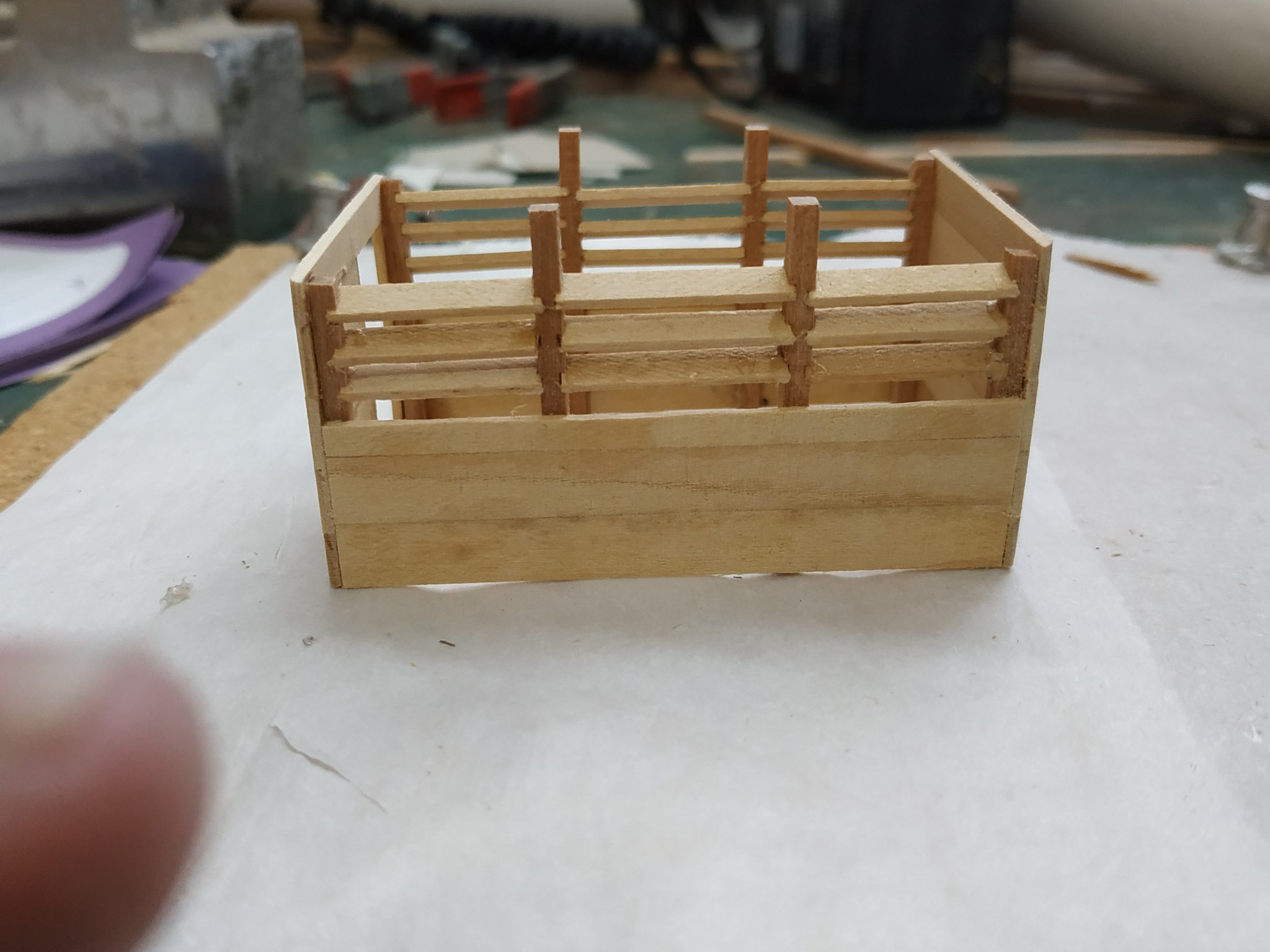
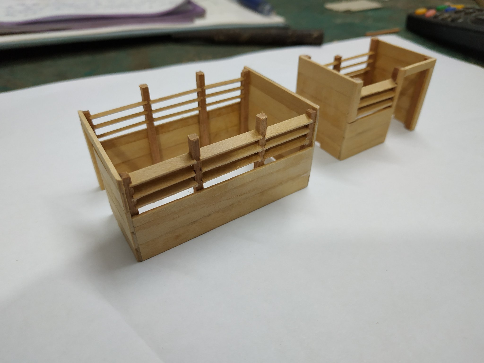
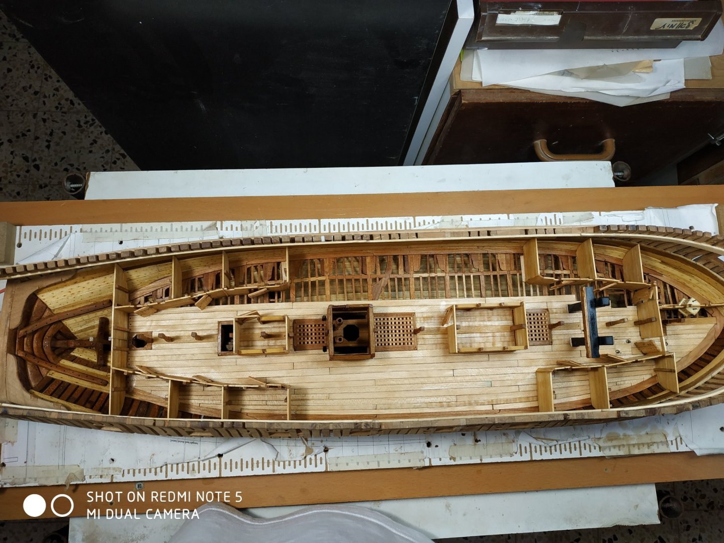
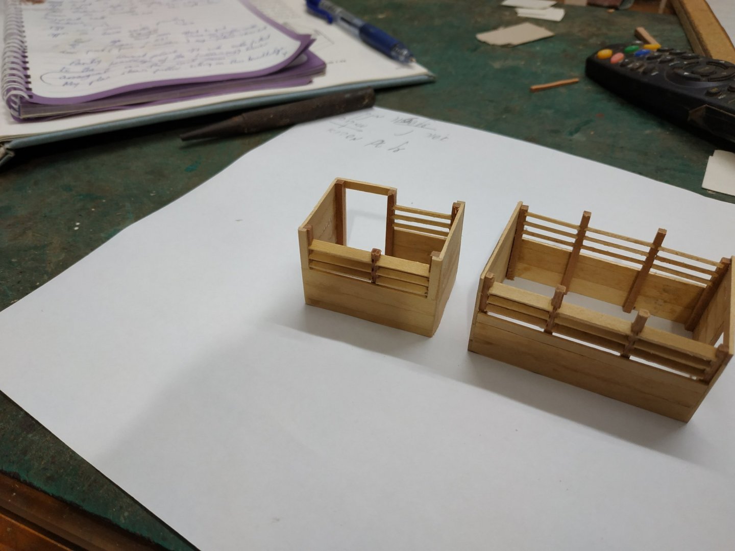
Lower Deck Structures cont. In the mid deck area, between the fore and aft deck cabins, are the Sail room and Pantry. (These are unpaired) The fore bulkhead of the sail room abuts the aft headledge of the fore hatch. The door is aft. The aft bulkhead of the Pantry, abuts the ladderway. The door is to the port side. The upper ⅓ of the sidewalls are lourved. The stanchions are grooved in the same way as the pump well (30deg. jig on sliding table).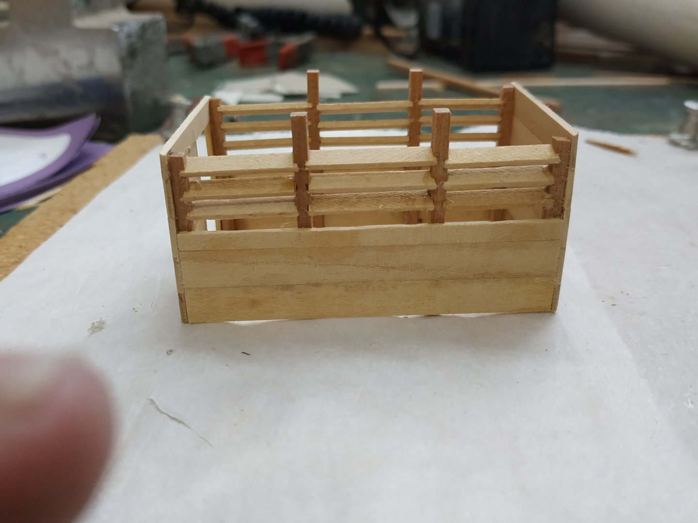

-
Swan-Class Sloop by Stuglo - FINISHED - 1:48
stuglo replied to stuglo's topic in - Build logs for subjects built 1751 - 1800
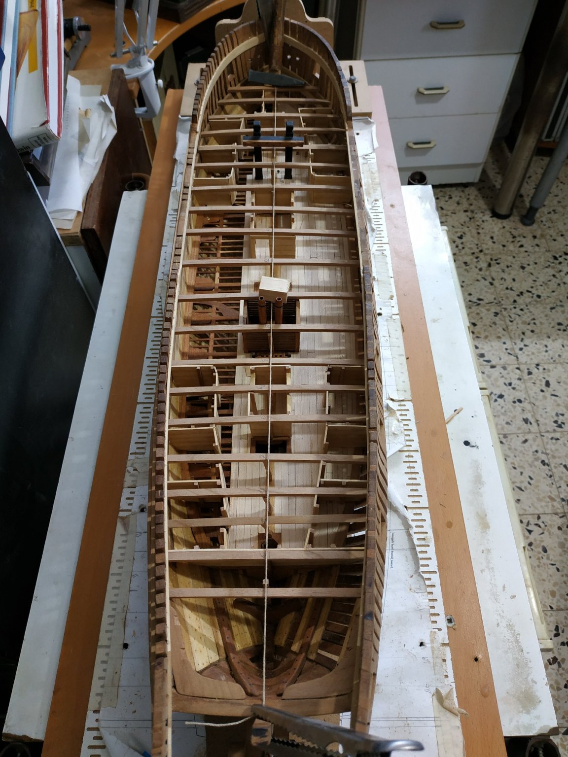
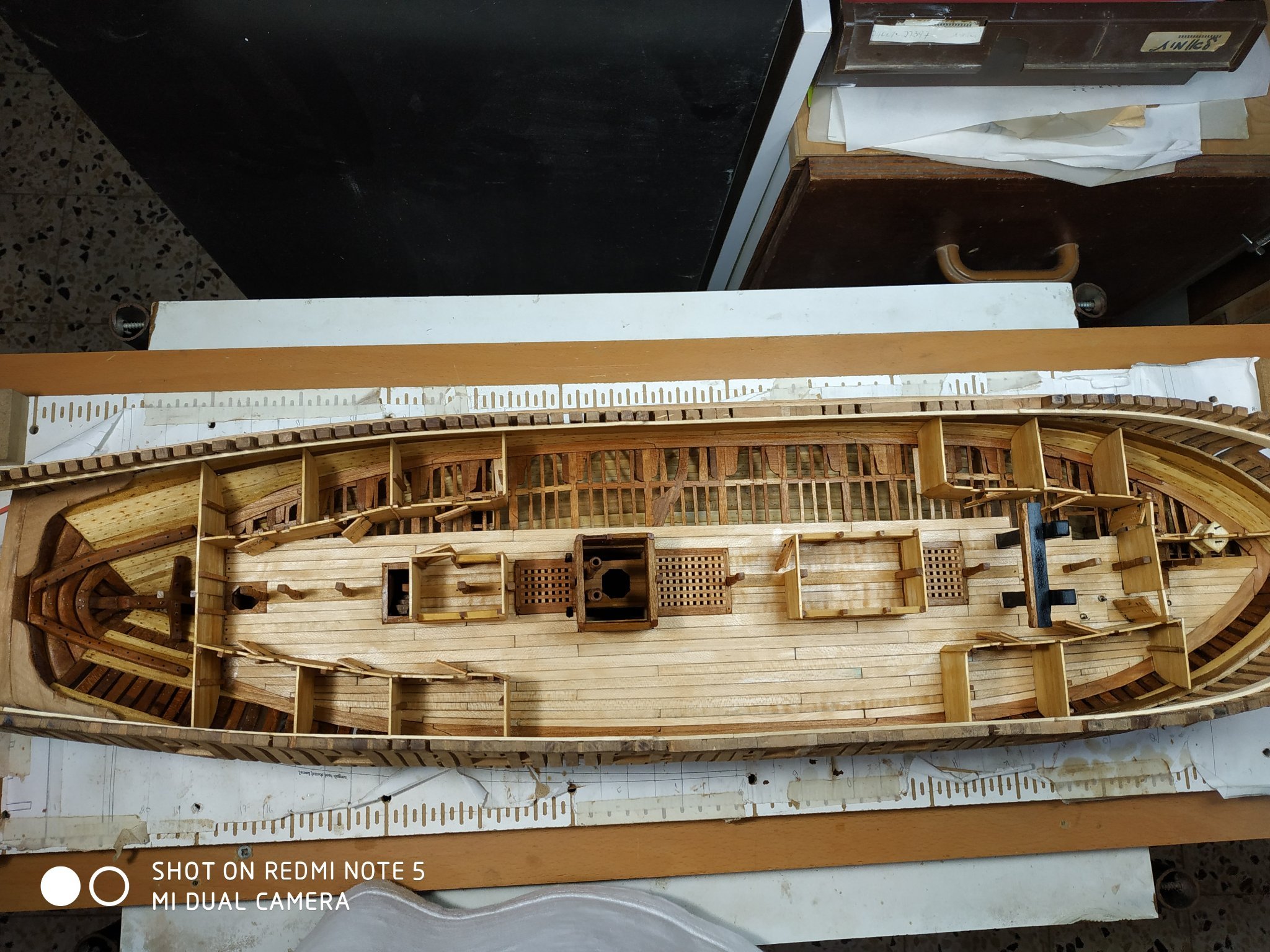
Lower Deck Cabin Bulkheads. TFFM says “ build up as you did the platform bulkheads” as if I can remember!! Even referring to relevant chapter and my notes, it feels almost like learning anew. This time however I will take better notice of height while building and not correcting afterwards. Therefore, keep beams in place and built around them. Stanchions 2.12 x 2.12mm.- The first bulkhead is forward aft running on the port side of the mast, ( to a athwartship bulkhead centred on the #3 pillar). It is made with short planks separated/supported by stanchions with rabbets. After breaking 2 thin milling bits, I used the alternative method with battens!! The cabin layouts are shown clearly in TFFM plan. Three pairs fore and aft, the first two unequal because of the offset separation bulkhead. Some have a narrow “angled” joining bulkhead which I found some difficulty in making. Several attempts still leave me dissatisfied with the result In order to maintain the horizontal and vertical angles, allowance and correction for the camber and slope are needed. Sometimes only after fixing, are errors apparent, but a sharp blade and alcohol can undo and allow for necessary corrections. Notches are made to allow beams to sit flat- other corrections for the deck architecture will be made as required. Further “simple” bulkheads (longer horizontal planks) for the aft of the deck are similarly made. The deck ends with an aft bulkhead that runs from side to side. Some more severe shaping was needed where it meets the hull, so I made it in 2 halves for ease.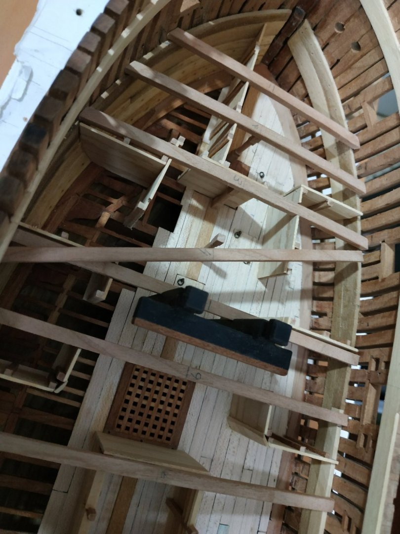

-
Swan-Class Sloop by Stuglo - FINISHED - 1:48
stuglo replied to stuglo's topic in - Build logs for subjects built 1751 - 1800
Thank you. I can't say enough how much we learn from your videos and comments. -
Great idea and I will make some. Sorry to seem stupid, but why do we need the deck planks tightly against each other. I usually leave a tiny gap to "emphasise " my non-existent caulking!!
-
Swan-Class Sloop by Stuglo - FINISHED - 1:48
stuglo replied to stuglo's topic in - Build logs for subjects built 1751 - 1800
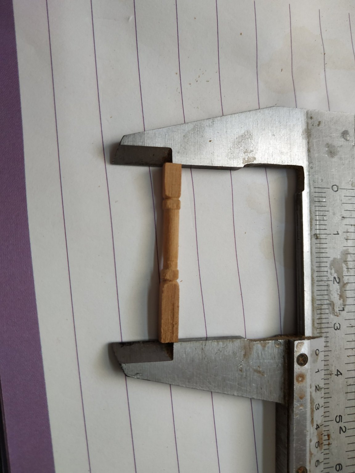
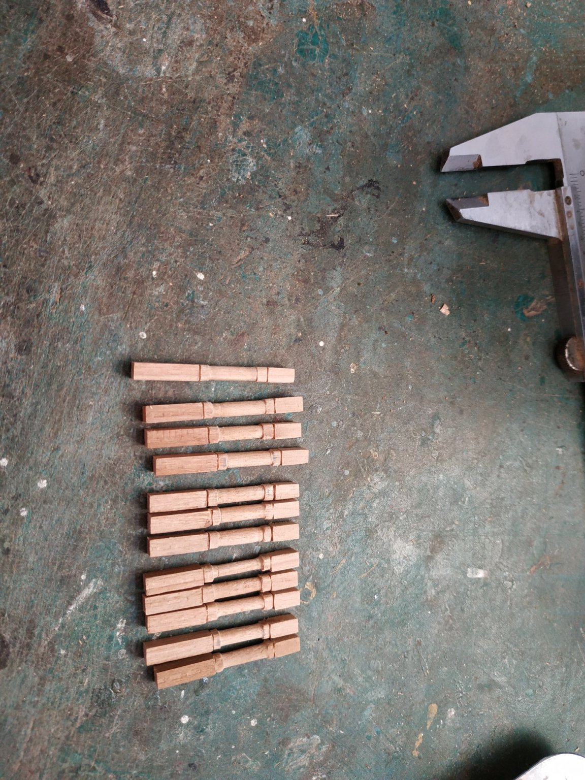
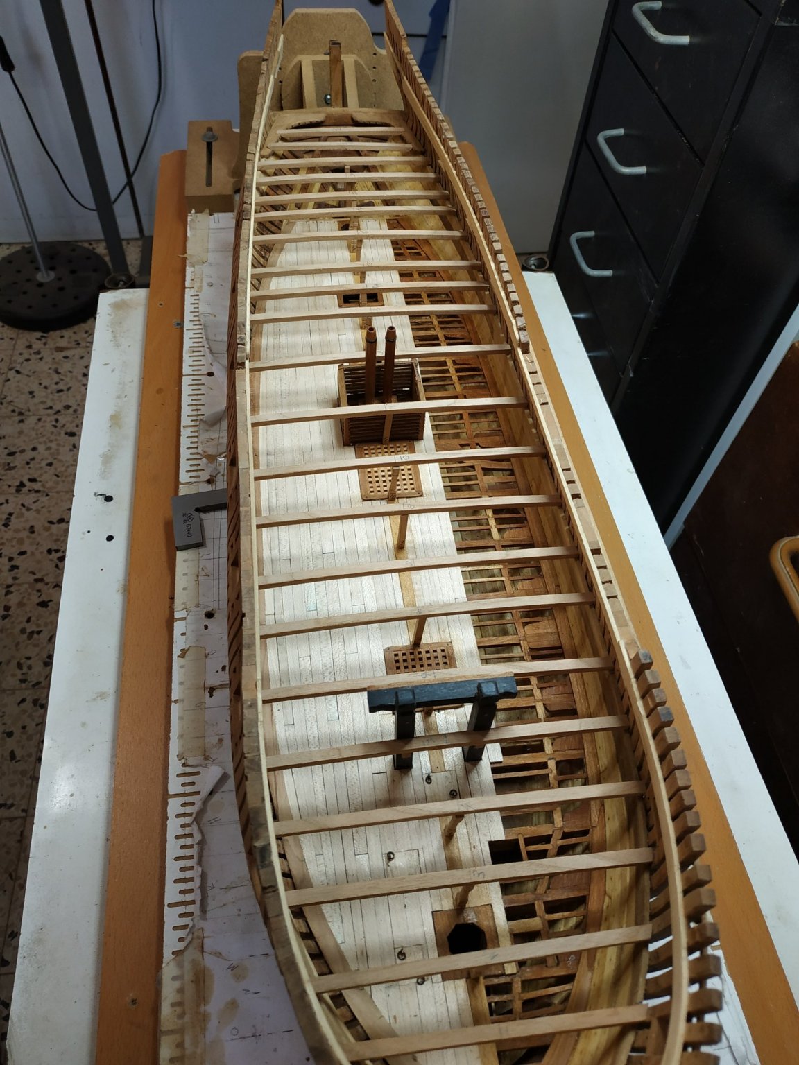
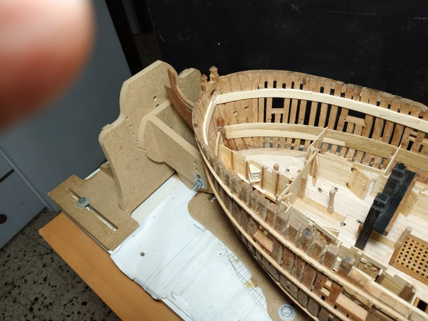
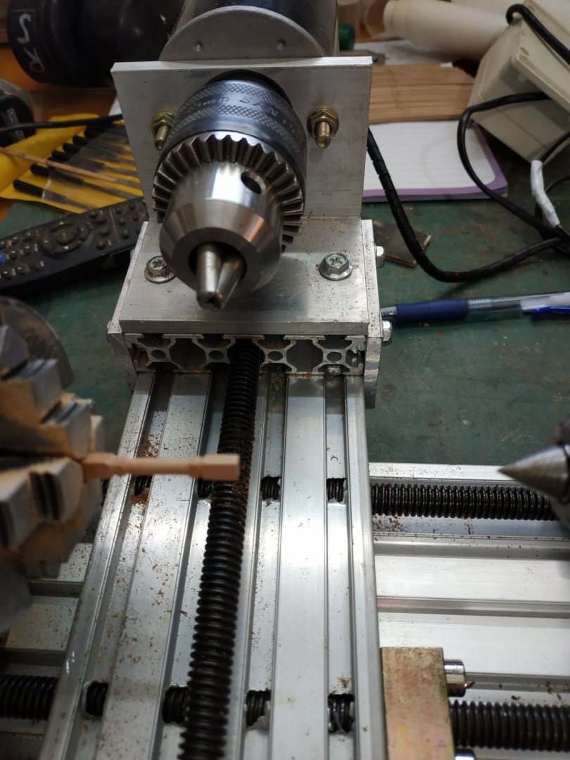
Pillars under the upper deck beams. The next step are the lower deck cabin bulkheads; but to make them more accurately and positioned correctly( without the later alterations that I was required to make for the platform structures) better reference to later structures will be used.Thus the pillars- which also require the temp. fitting of the upper deck beams.Positions located on plans. Some coincide with structures such as coamings and there seems a difference on how to treat these- notch the structure or have the pillar sit on it. Eleven are shaped- for beams #2,3,4,6,10,13,14,15,16,17,18 4 are plain-squared- #7,9,11,12 Previously made (at time of pillars beneath lower deck)- #19,20 Instead of tenons, copper pin into foot and underlying structure. Options for shape in TFFM and plans. Dimensions given-the head-2.9x2.9mm and heal 3.45x3.45mm The centre ⅔, rounded- narrowing upwards to match the thinner head. The height to be set individually beneath each beam - therefore made heal overlong for later shortening. (Little experience with turning small structures and my Unimat has a 3jaw chuck- not good for square pieces. Bought the contraption shown in the picture for such work. Overpriced, poor quality and very inaccurate- but having bought it, used it) Beams and Pillars dry-fitted.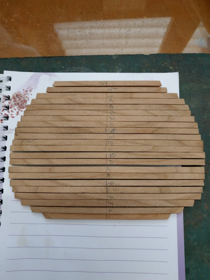


-
Swan-Class Sloop by Stuglo - FINISHED - 1:48
stuglo replied to stuglo's topic in - Build logs for subjects built 1751 - 1800
Sorry, been away and just noticed your question. I "slimmed down" the pipe and opened the hole to arrive at 9.5 inch. (lower deck level) . Not fixed yet because may need to reduce height. Hopefully, soon will see what happens with upper deck level. -
Swan-Class Sloop by Stuglo - FINISHED - 1:48
stuglo replied to stuglo's topic in - Build logs for subjects built 1751 - 1800
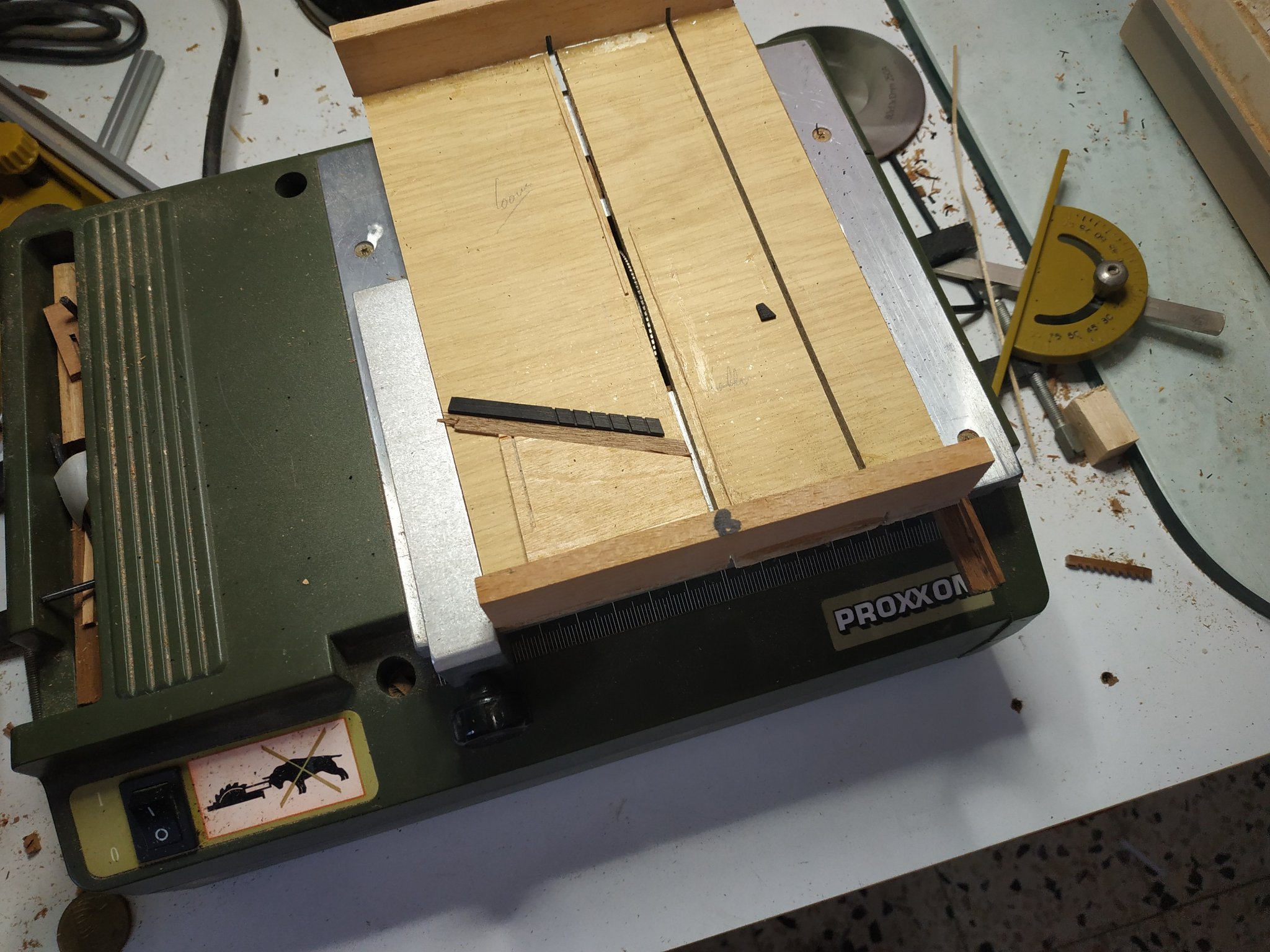
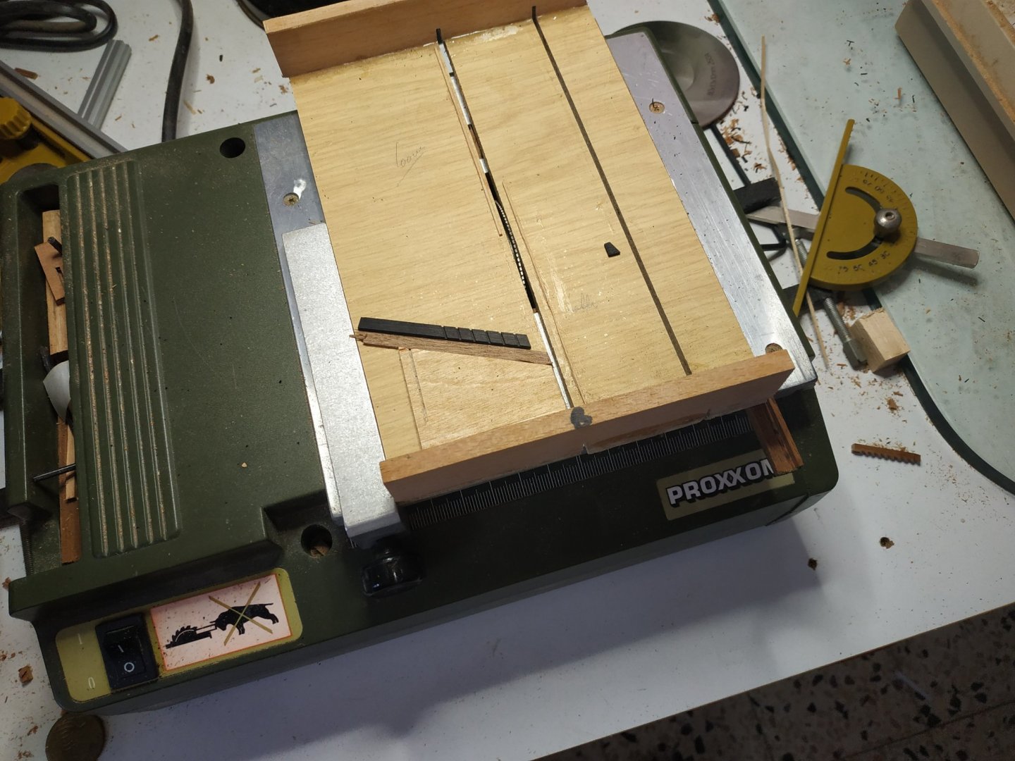
Ladder (Back to building after 10 days in and around Napoli-Fantastic place-visit if you can.) Styles (sides) 0.8-1mm (size apparently flexible)-each with opposite direction of slots. Treads (steps) 0.53 x4.24mm The ladder feet are on the port side, inclined at 65deg.-this angle sets the slots horizontal and an angled jig can be used along with the “grating” method. I have a smaller Proxxon table saw which has a 0.5 wide blade. No height adjustment so wood raised by another piece of suitable thickness. The Styles are shaped- the top notched to fit the coaming, then other corner chamfered. The middle ⅔ are narrowed by 0.75mm (supposedly to lighten) Overall length to fit .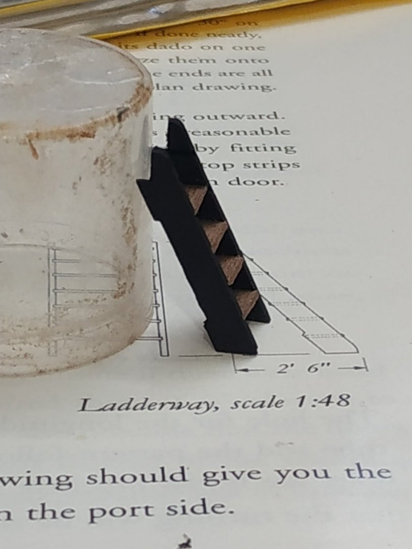
-
Swan-Class Sloop by Stuglo - FINISHED - 1:48
stuglo replied to stuglo's topic in - Build logs for subjects built 1751 - 1800
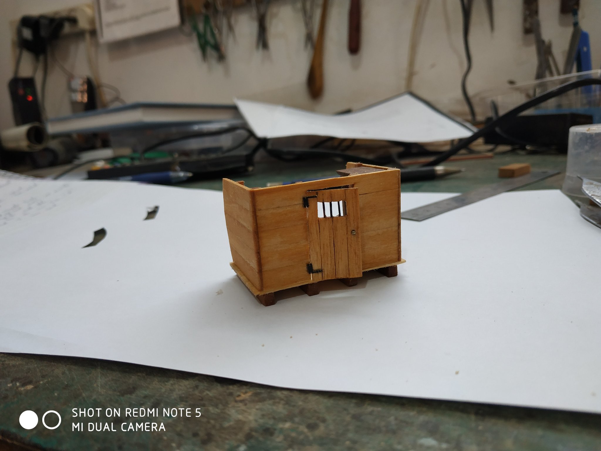
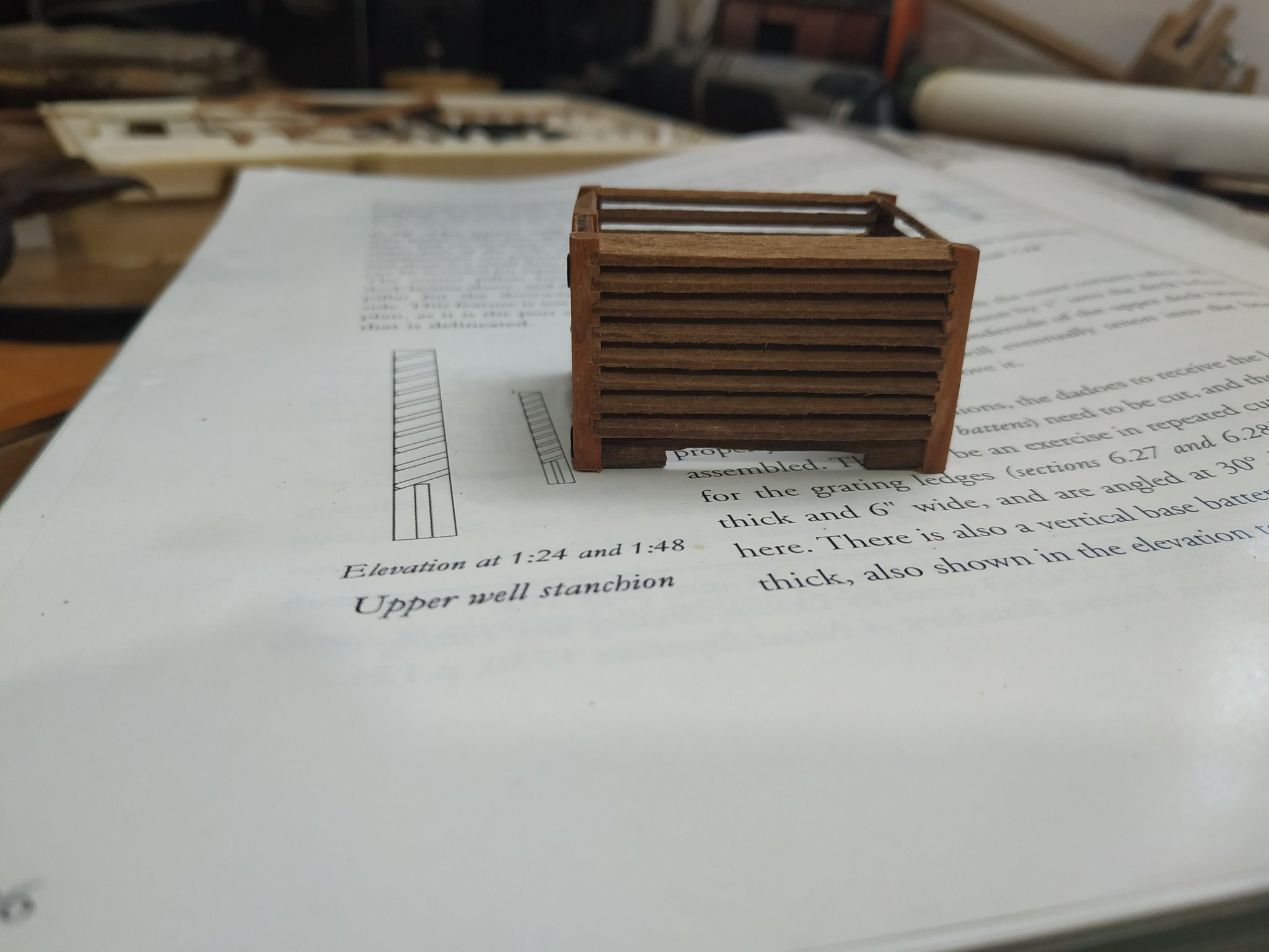
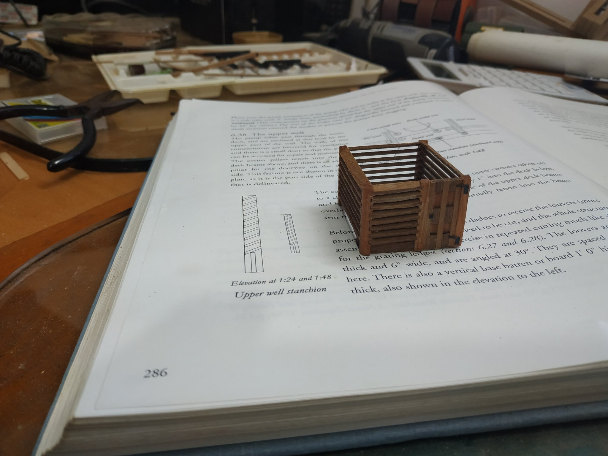
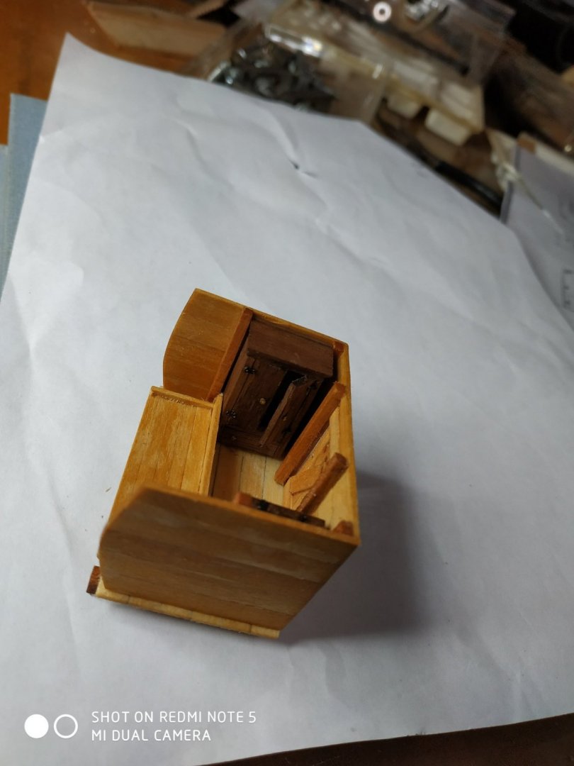
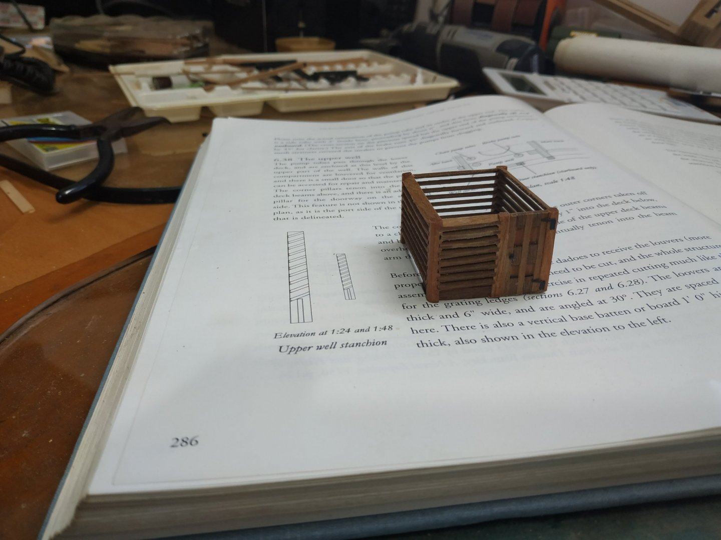
Upper Well As the pumps pass through the lower deck, they are enclosed by a Well or compartment(-as they do below the deck). It consists of louvred walls and a small door (port side). Corner pillars extend to the upper deck beam, and a pillar for the doorway-3.18 x 3.18mm. Loovers 0.8x4mm and angled at 30deg.seperated 1.5mm Vertical bottom plank 6.36x0.8mm notched athwartship to allow for mast partner. Main challenge is the slots in the posts. Following the ideas for making the gratings, by using a fine tooth Proxxon table saw blade (miraculously 0.8mm) and a 30deg jig. Remember directions of slots to allow the looves to match between posts. Also vertical slots (milled) for the vertical bottom plank. A simple door. The overall size to fit space between main and aft hatches and cover the lower well. This was a fun piece to make.
-
Received replacement parts, but I incorrectly ordered one of them and despite correcting it the following day, so efficient, I received this incorrect part. Requested this again. Not their fault really. PS the parts came properly packaged with plenty of filling.
-
Swan-Class Sloop by Stuglo - FINISHED - 1:48
stuglo replied to stuglo's topic in - Build logs for subjects built 1751 - 1800
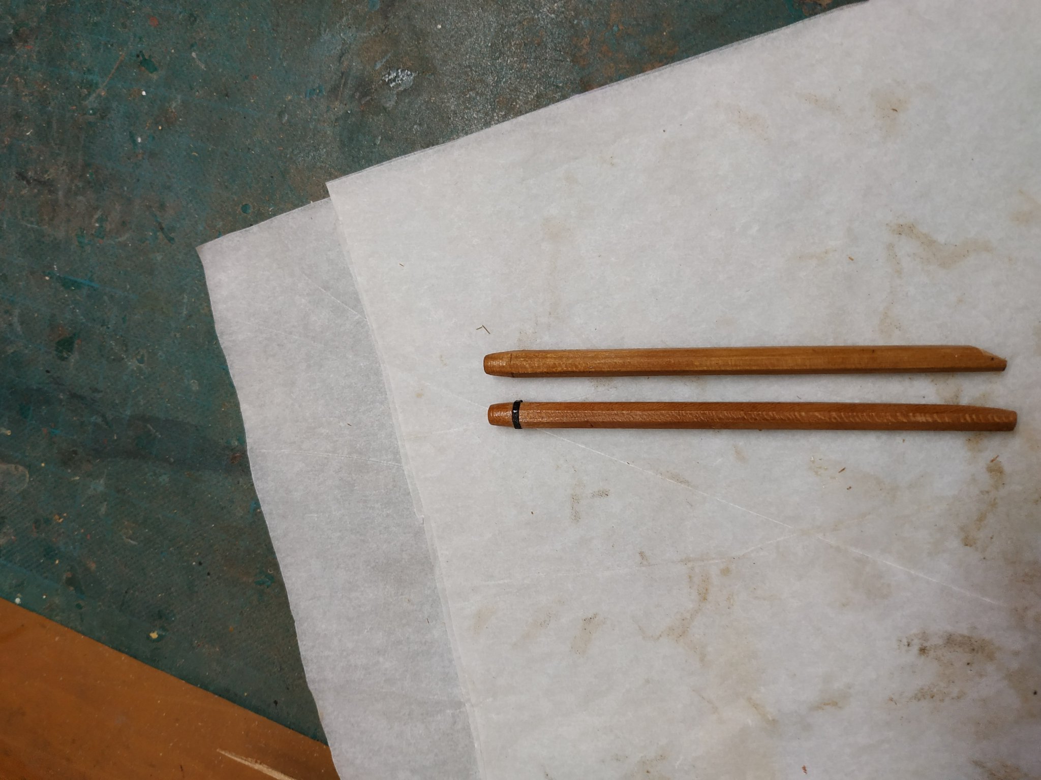
The Chain Pumps. As usual, TFFM gives a good explanation. A down (Back) tube, inboard,with intake at base. An up (Discharge) tube . These are topped with an assembly including a wheel and roller. Surrounding these is a cistern. The tubes are pencil-shaped,98mm long, 5.3mm wide at top and tapering to 4.0mm at bottom. There is a consistent bore of 2.65mm, therefore the wall thickness thins significantly. There is also a pair of Brake pumps, similar in external size but with a narrowing bore (to 2.4mm) which is essential for its mode of function. I used 5.3x5.3 blanks, 100mmlong. Holes drilling in initial few cms. With a drill press-enure bit is centralised Already had the jig as suggested, but my skill with a plane is lacking. Still able to use the “7-10-7” rule as suggested, but used a mill instead. Dusting of my Pythagorus, (? remember the song” the square of the hypotenuse….”), the depth of cut can be easily calculated.=1.1mm The corners are milled off and we have 8 sides. The tapering achieved by raising the lower end with a 0.65 slip of wood,remilling against the gradient with a slightly shallower cut. The top 6mm of all are rounded (like a pencil) to a diameter of 4mm.Where this starts,a collar of 2mm black paper to mimic an iron band. The Brake pumps have a modified band which can be fitted later. These also have a modified lower end- inboard is shaped like a fountain pen nib. Finally, a hole to allow a 1.6 bore pipe (a short discharge tube), to protrude aft/outwads at 45deg.- I set this after checking the upper deck level. ( I have purchased a set of Photo-etched details from a fellow Swan builder) I tried to build the Pump Intake Chamber-too fiddly and no patience) *****This means that the Tubes will sit lower and this should be allowed for***** (After the complexities of the Bitts, this was FUN)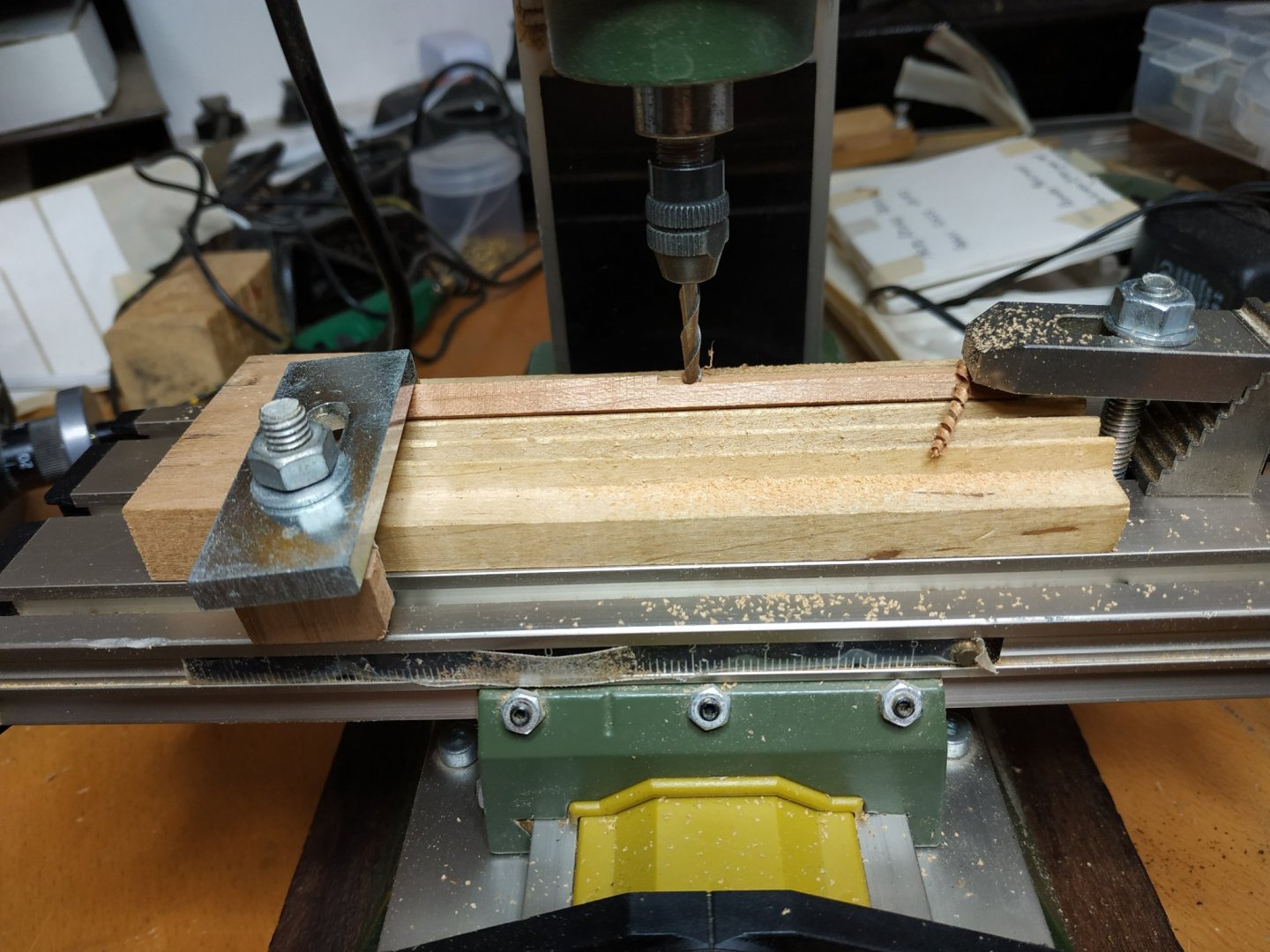

-
Swan-Class Sloop by Stuglo - FINISHED - 1:48
stuglo replied to stuglo's topic in - Build logs for subjects built 1751 - 1800
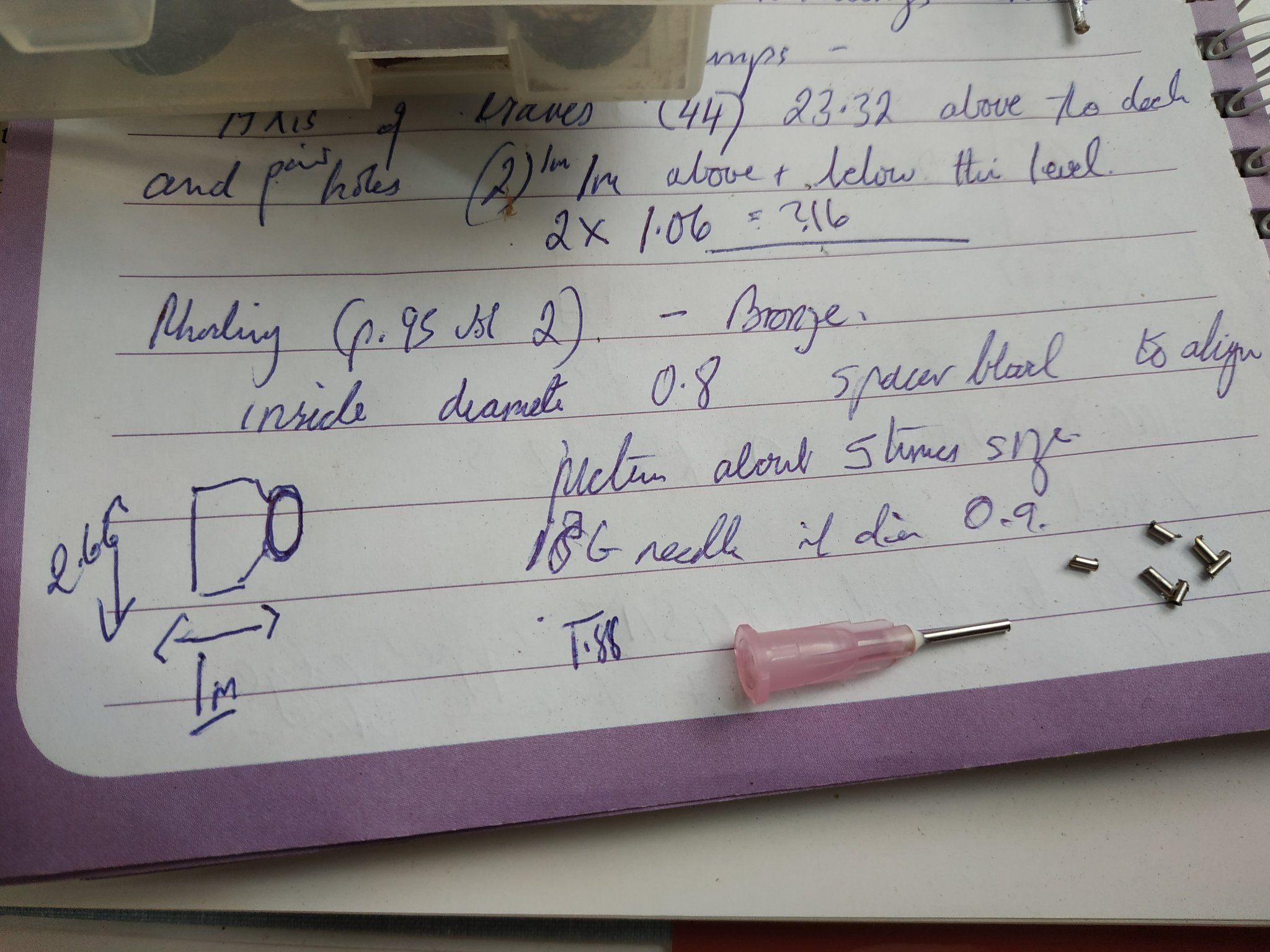
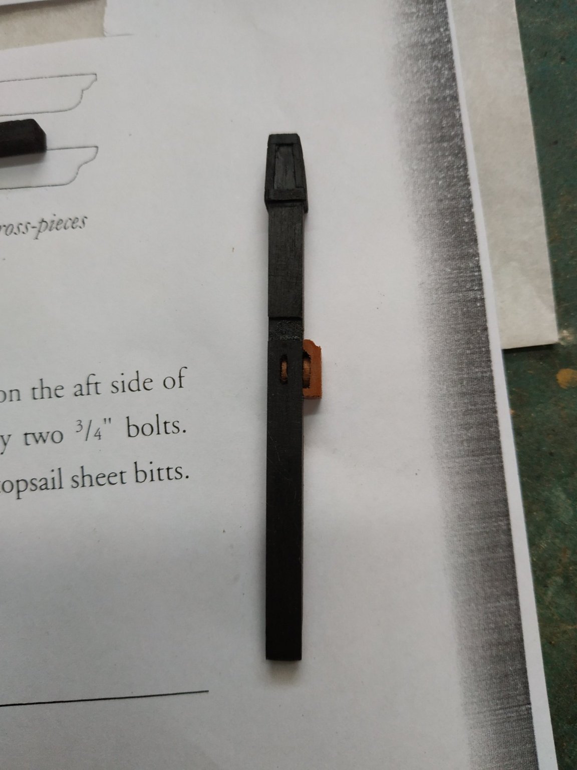
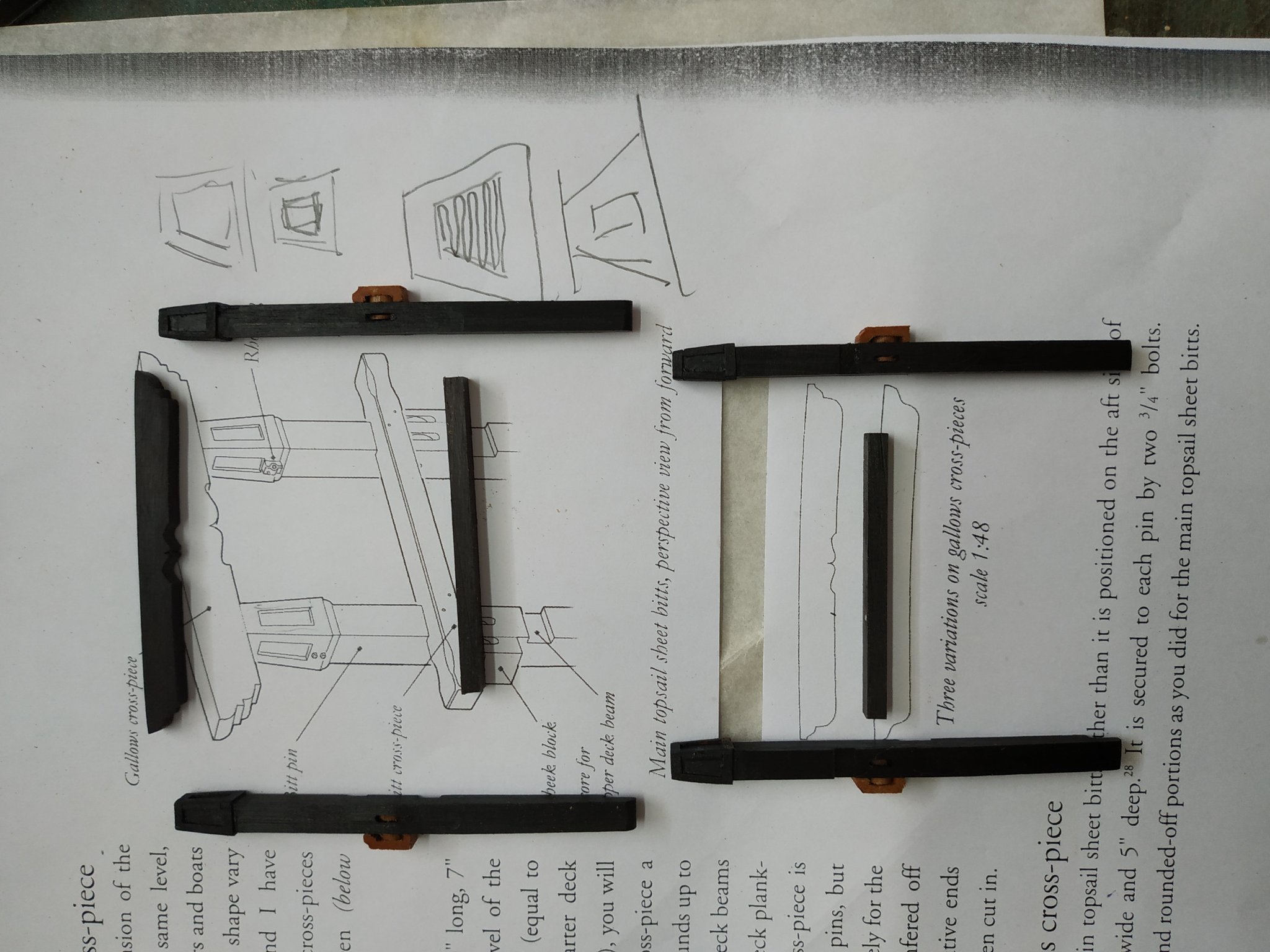
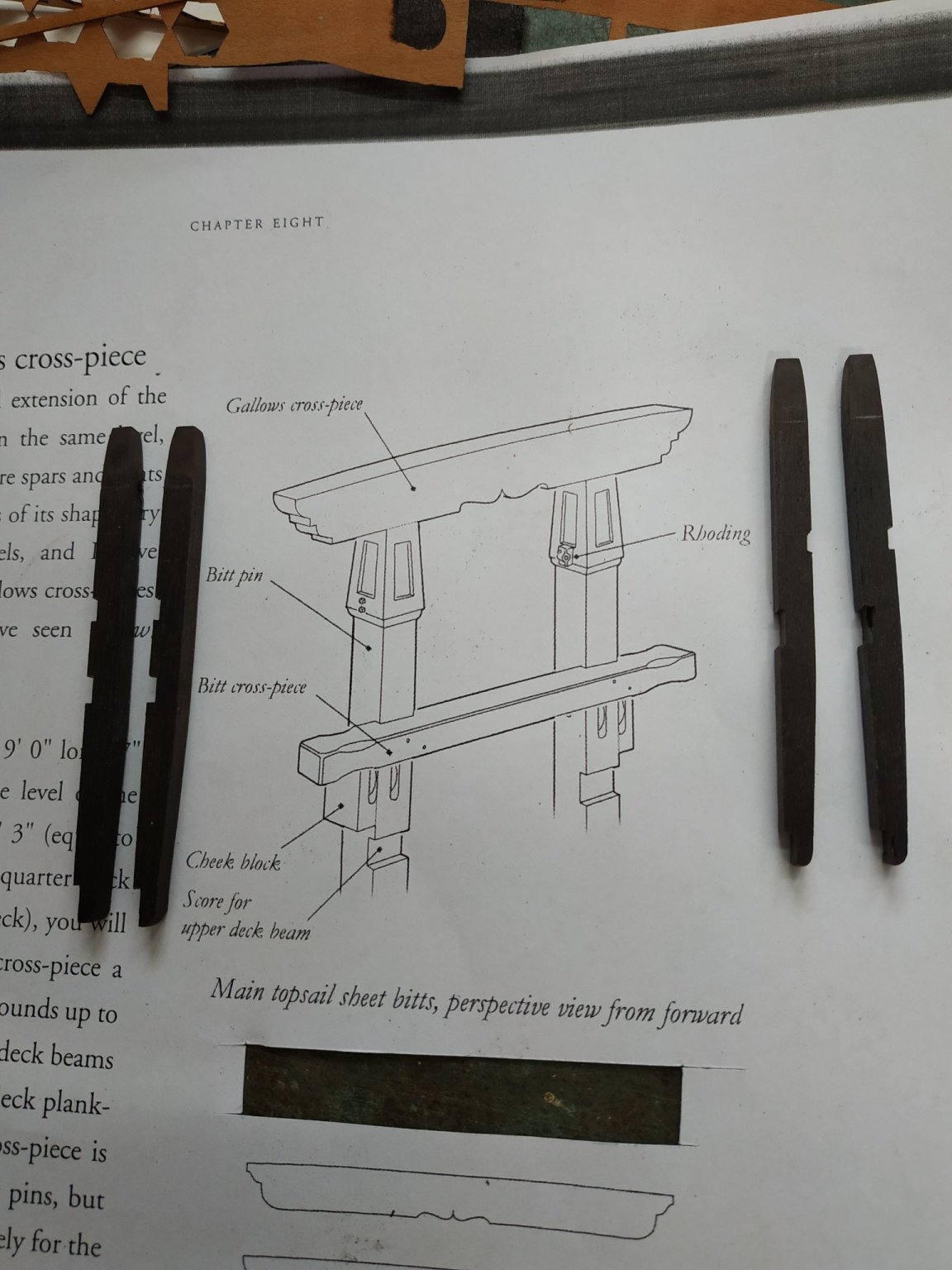
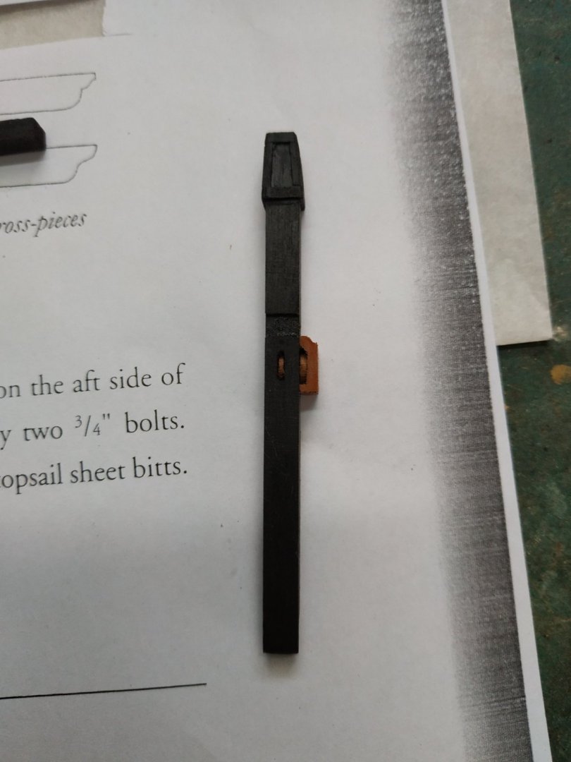
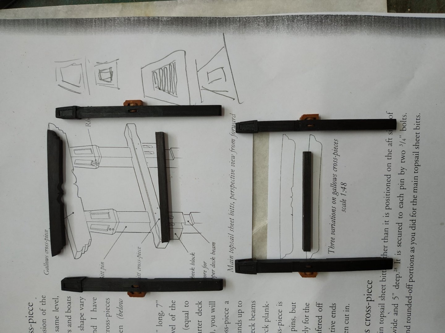
Main Topsail and Main Jeer Bitts (almost finished). Next suggested making holes for the Pump Brake Rhodings- bearings that hold the crank handles. Set at an axis of 23.32mm above the deck - one hole above and another below separated by 2.16mm. Decided to make and fit them now-see vol 2 TFFM Suggested made of bronze with an internal diameter of 0.8mm The MT Bitts have a wider separation than the MJ pair and therefore they have spacer blocks to compensate (maintain alignment). Again no suitable brass tubing, so used a 18G needle (medical) which has an int. Diameter of 0.9mm.Later added a spot of copper paint. The Spacer,a wood strip, 2.66x1.5mm, grooved to depth of 0.75mm to take a length cut off from the needle. I made it 2.5mm wide. In retrospect it is probably too wide. I epoxied similar lengths to the MJ bitts. Used copper pins,but actually forgot to square the heads for the locking nuts. Fitted the cross pieces and Gallows - just remember which “bit” goes with what and where
-
Good luck -remember the alcohol.
-
Swan-Class Sloop by Stuglo - FINISHED - 1:48
stuglo replied to stuglo's topic in - Build logs for subjects built 1751 - 1800
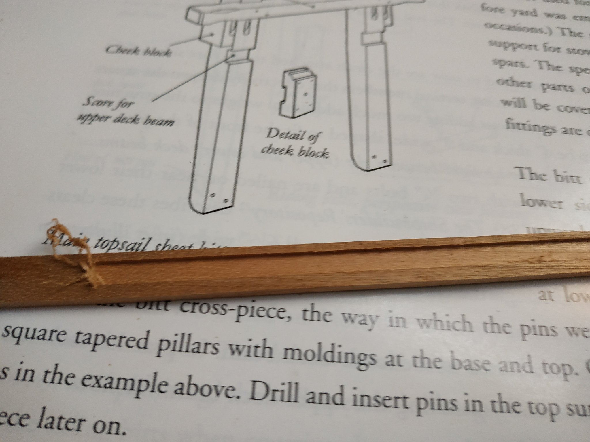
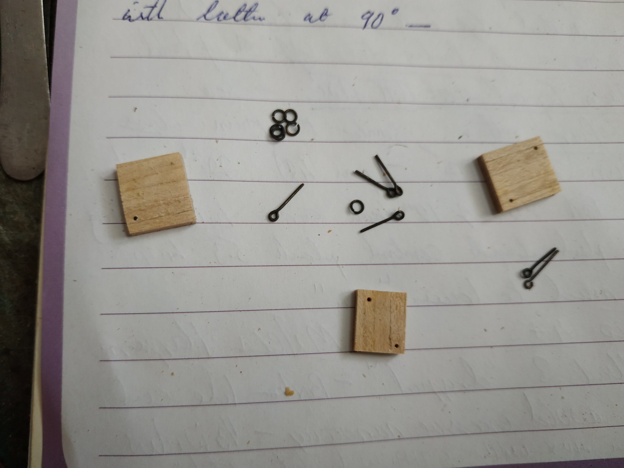
Main Topsail and Jeer Bitts (continued further again) CHAMFERING AT THE BITT to finish- moved on to the Cheek Blocks. These thin structures - like a flattened “C” cover the outer sheave (single pulley disc) This sheave is 4mmx0.6mm. I took the height as 8mm, width as 4.77 (as pins) and thickness, 2.5mm. The Cheek blocks sit on the deck, the portion above the sheave is thicker and finished as a molding. Taking a blank 8mm deep,2.5mm thick and 20mm long , I Milled a groove 0.8 deep (it turned out 1.0mm) and 4.2mm wide - leaving 1.5mm wood to base and side, and 2.3 above. The thicker top was milled with a shaped bit to produce the molding. (I tried , for the first time, the Artesenia molding tool with little result) Good result, but I stupidly put the molding facing inward- Start again! Cut slices to appropriate width-4.77mm The Pins have a matching slit, at the same level, but for a sheave slightly wider at 0.93. As I have no brass rods,(which I couldn’t cut to size anyway), no same-size metal washers, I cut them from a 4mm rod. I think they look OK.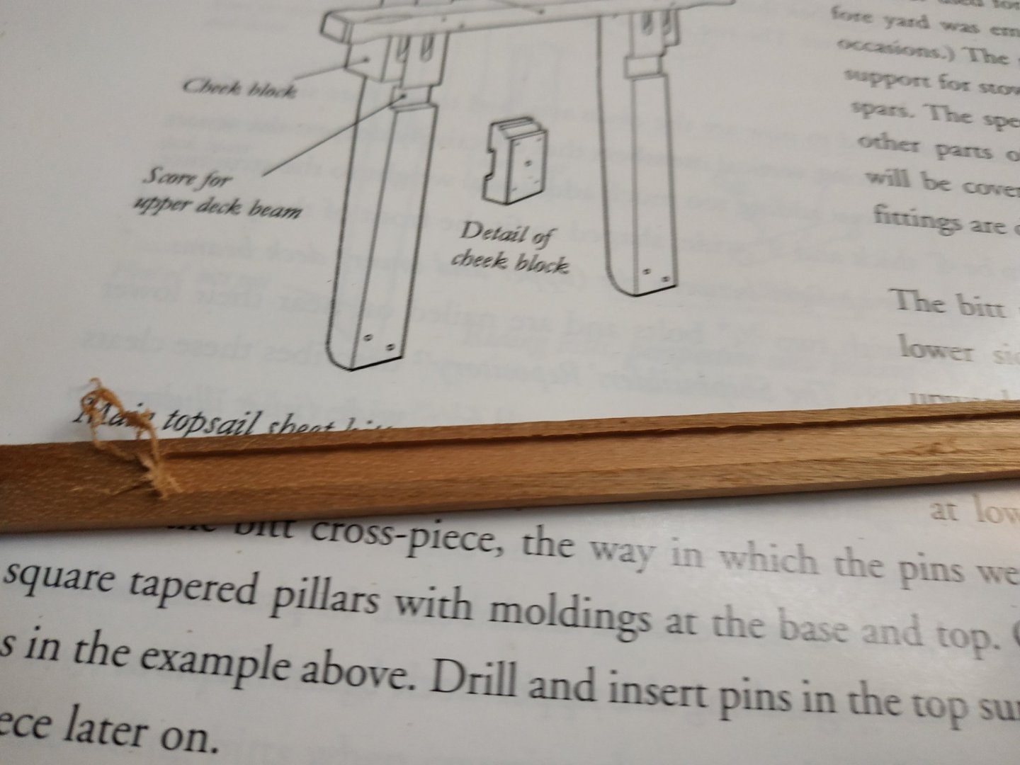
-
Swan-Class Sloop by Stuglo - FINISHED - 1:48
stuglo replied to stuglo's topic in - Build logs for subjects built 1751 - 1800
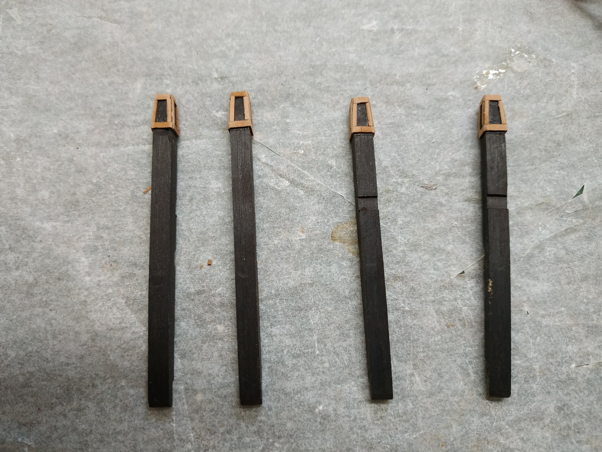
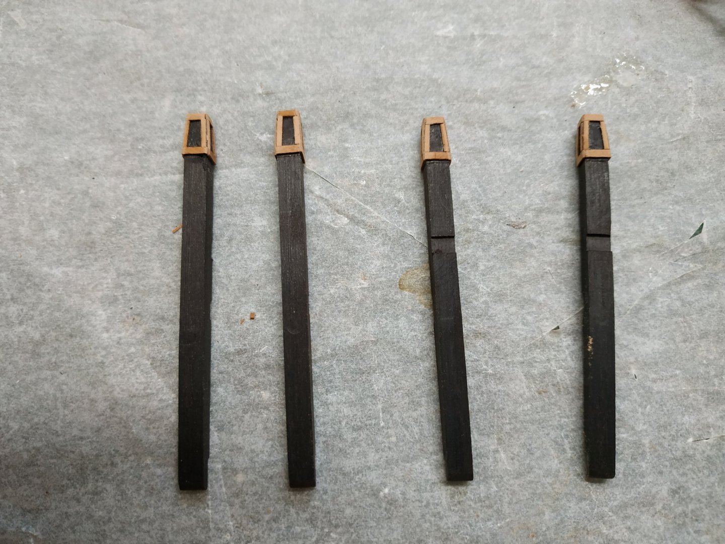
Main Topsail and Jeer Bitts (continued further) NOW we notice that the fancy top to the pins are not straight but have a sort of mushroom top (or something else which I shan’t mention)- suddenly wider then tapering. At first glance I see a number of possible solutions:- Remake the pins to widest dimension and shape back Make a separate piece to stick on to a shortened top Add a thickening blanks to shape and then carve decoration. Taper existing end and add battens to form a rhomboid shaped “window” Checked KK’s video-he went with the last option. I could have done with then tilting table he used for milling, but used a stationary sanding block to reduce the top10mm of the pins from 4.77mm to 3.77mm-result could have been better but I was impatient. I have left over from Dusek’s La Real cutout sheets some strips 0.5mm thick and varying 1.2 to 1.5mm wide that surround parts cut out by laser.(remember never to throw anything away). The wider stuff for the top and bottom, alternating thin and thicker for sides to overlap. Chamfering to round edges and blend corners. Soome black acrylic paint matches quite well. (Just to the additions.)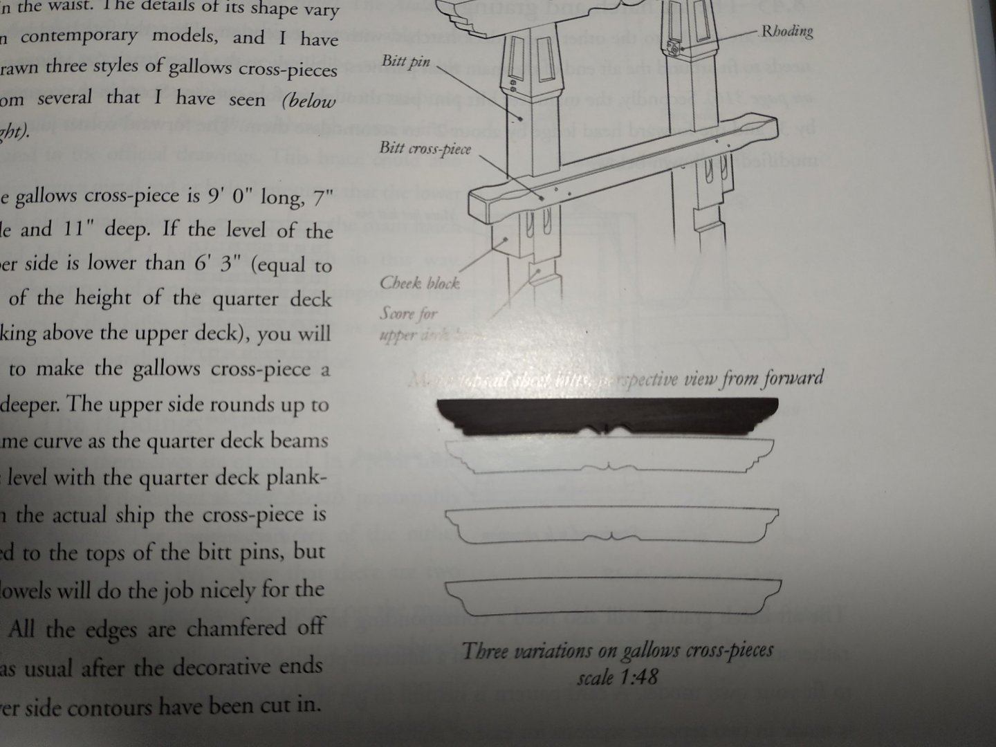

-
Swan-Class Sloop by Stuglo - FINISHED - 1:48
stuglo replied to stuglo's topic in - Build logs for subjects built 1751 - 1800
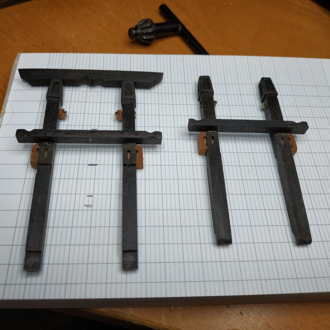
Main Topsail and Jeer Bitts (continued) I’m posting the various stages in (I hope) digestible bits (pun intended) Of course, cut the blanks slightly overlong. Place an upper deck beam in position and measure and mark the upper surface height above the lower deck, on the Bitts. The Aft surface is tapered below this line by about a ⅓-to 3.5mm A “Heel” is then formed on the fore surface- notched to depth similar to a beam’s depth and about 2.50mm thickness left. This attaches to the top and side of the lower deck beams. The Main Jeer Bitts: The hole in the corner of the after hatch should be enlarged to accommodate the Bitts, allowing for a separation of 22.26mm (Main Topsail Bitts are separated by 23.85mm but there is space for this in the pump well.) The Bitts are now scored to depth 0.75mm on fore aspect to allow them to fit the upper deck beams. The Cross Pieces -Main Topsail Bitt 3.10x4.25mm-with different lengths to choose from,I made it 51.25mm -Main Jeer 3.10x4.25x45.9mm **NOTE**that the Jeer Bitt has the cross piece AFT of the Pins. Also scored 0.75mm, the UPPER surface of the Cross Piece, is 11.13mm above the upper deck. -
Swan-Class Sloop by Stuglo - FINISHED - 1:48
stuglo replied to stuglo's topic in - Build logs for subjects built 1751 - 1800
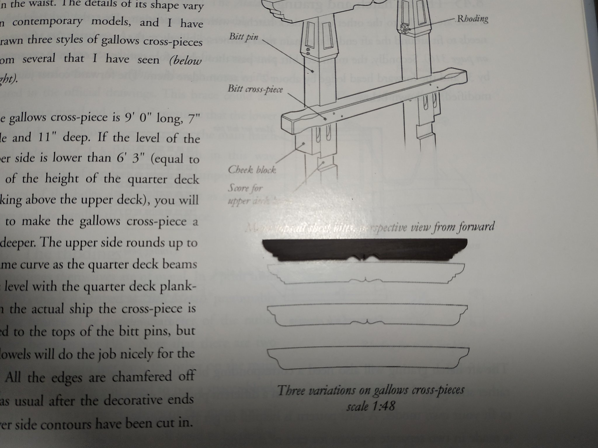
Main Topsail Sheet Bitts and Main Jeer Bitts. Having made the Riding Bitts, I thought these would be similar and relatively easy-HA! HA! HA! Initially a lack of information in TFFM, then excess after searching vol 2 .Further complications when I tried to understand using the Peter Goodwin “construction and fitting” book. Different measures are given here. Also my profile and deck plans weren’t in agreement with anything. So checked up on Kevin Kenny’s video, to find he was also troubled and remade them (in video 80). After many scribbled drawings, I decided to remember an earlier solution-take each stage as it comes. Maximum will have to restart. Firstly, size of blank- 4.77 X4.77mm . But what length? The length of the MTSB pins is such that they allow the upper surface of the Gallows Piece (a fancy cross piece sitting on the pins) to be in line with the surface of the quarter deck and to follow its curve. In order to know the height of the quarter deck, check profile plans to ensure the the strakes/clamps are in the correct height- and note beams are only 2.9mm deep, but planking is 1.33mm thick. So I start with the Gallows piece - I took a blank of 60X3.75X7mm. I stuck a copy of the 1st option of patterns given inTFFM and sanded a curve to match- so that the depth was 5.83mm. I then used a couple of interesting- looking milling bits to obtain the result required at either end and underside of this curve, so the length was 57.2mm. The length of the MTSB pins are therefore height of quarterdeck above the lower deck, minus depth of Gallows plus the “Heel” inside the pump well-which in my case is 75.75. You could read it off the plans but mine are unclear with superimposed markings) I’m going to make the Main Jeer Biitts at the same time as the dimension of the blanks and workings are similar 4.77X4.77mm Its length is such as to support the fore beam of the quarter deck - ie previously calculated height minus the thickness of beam and planking. With the “heel” this comes to 72.70mm -
Swan-Class Sloop by Stuglo - FINISHED - 1:48
stuglo replied to stuglo's topic in - Build logs for subjects built 1751 - 1800
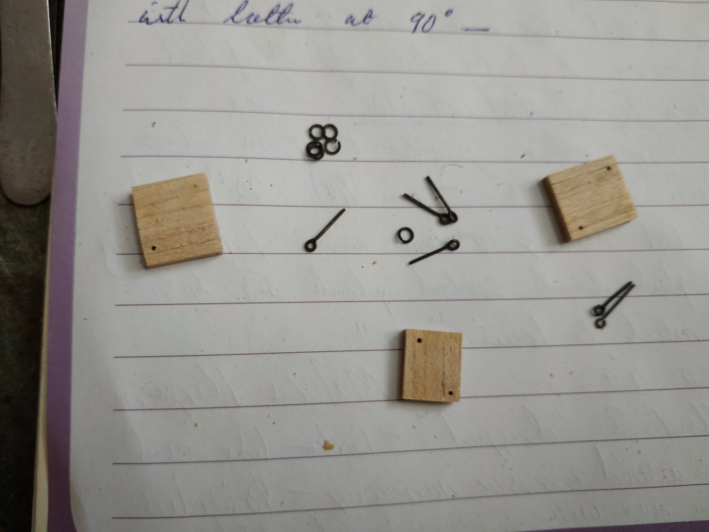
Scuttle Covers To the side and aft of the foremast. Flush to deck. TFFM says battens on the inner side of carlings, but at least one of my scuttle doesn't have these-so just “fit” them so they don't fall when glued.Also ignored hinges. The upper surface planks are narrower, they are supported by battens at 90deg. The ring and bolts from an old kit of similar scale.