HOLIDAY DONATION DRIVE - SUPPORT MSW - DO YOUR PART TO KEEP THIS GREAT FORUM GOING! (78 donations so far out of 49,000 members - C'mon guys!)
×


Tony Hunt
-
Posts
543 -
Joined
-
Last visited
Content Type
Profiles
Forums
Gallery
Events
Everything posted by Tony Hunt
-
It is indeed a wonderfully detailed image from a very useful vantage point - if only you could trust the details! In addition to the anomalies you point out, the cross-wise planking on the poop seems a bit strange too!
-
What a superb model. Thanks for sharing the build with us Valeriy, it has been a pleasure watching every step of the way.
-
Superb work Ilhan. The cabinetry is wonderfully regular and symmetrical. Just like the real thing!
-
Those jibs look very realistic indeed. Nice work!
-
Great pictures Valeriy. They really illustrate how things worked. So valuable when building a detailed model like the SS Blagoev.
-
Valeriy, those tiny hooks for the cargo handling equipment are fabulous! I really admire your propeller soldering jig too. The SS Blagoev is looking almost complete - how much more to do before it's finished?
-
Jmiba, can you suggest a good tutorial to use to get started 3D modelling ships in Blender? There are way too many on Youtube to choose from!
-
Thanks Terry, Jmiba and CCClarke for your replies. Interesting insights! I'll give it a crack and see how far I get.
-
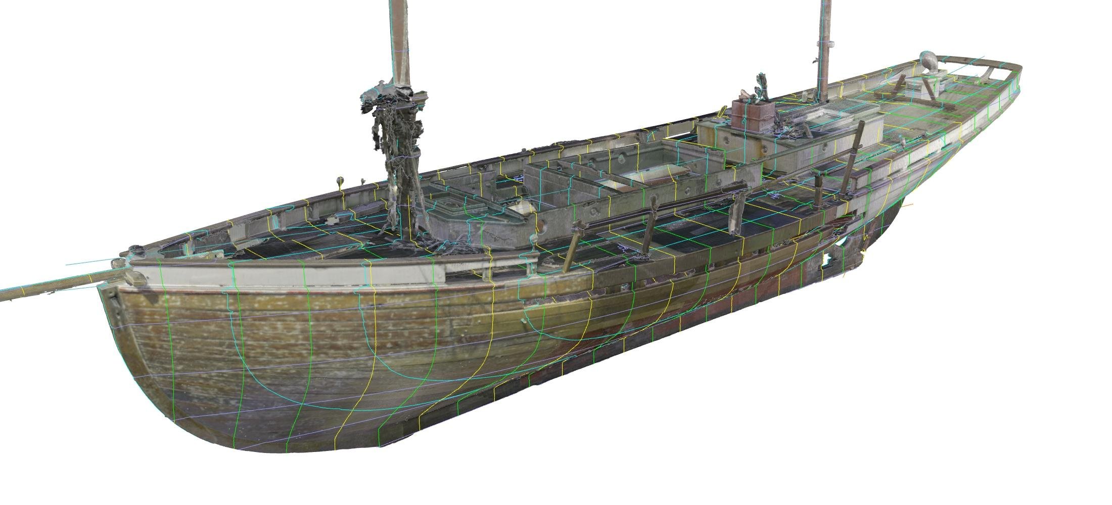
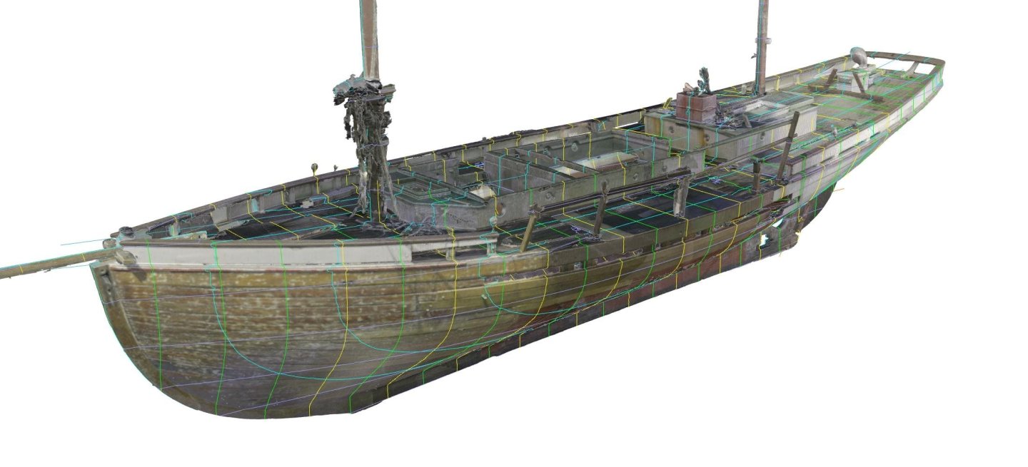
Hmmm. Methinks I haven't explained myself very clearly! I'll try again. The idea was to create a sketched 3D rendering of the hull, using the photos to get the shape approximately right, then use the clever ability of the 3D software to view the resulting 3D shape from the same viewpoint as the photographer who took the picture and overlay the rendering onto the picture. Kind of like the beautiful 3D rendering of the the pearling lugger PENGUIN (see below, done by a real Naval Architect, not me!) but much simpler. Any discrepancies between the rendering and the photo could then be noted and adjusted, until the two aligned perfectly. Yes? No? It won't work for the underwater shape, of course, but should be possible for everything above the waterline.
-
She's fairly typical for that period and that location. A lot of the early luggers were remarkably small. A surprising number were built overseas, in both Singapore and Hong Kong, and also in New Zealand. I guess Hong Kong isn't much further from Darwin than Sydney is! I think you could certainly use some of the plans already in existence as a starting point, then use the photos to refine them. There was a wider range of shapes and styles of pearling luggers than most people appreciate, and the point would be to create a series of small waterline models that illustrated that range of diversity. Yet another project for the future! 🙄
-
Welcome! There is a very active group of Donal McKay enthusiasts posting on MSW. The most recent thread is about STAGHOUND, but the masterpiece is the research they have done on GLORY OF THE SEAS. You have a lot of enjoyable reading ahead of you!
-
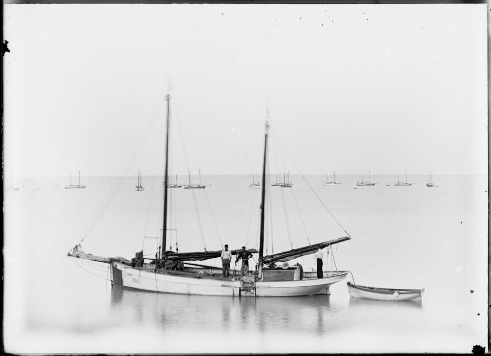
I'm wondering if it's possible to generate a 3D rendering from a good photo that would enable an accurate waterline model to be built from the resulting plans. Let me explain... 😀, using the two images below as a live example. They show two consecutive views of a small pearling lugger that operated from Darwin in the Northern Territory of Australia, named PETREL. An interesting little boat, it was built in 1898 in Hong Kong, by the Whampoa Dock Company Ltd, and was then shipped (unrigged) to Darwin as deck cargo on a steamship. PETREL was registered, so we also have two accurate dimensions to apply to the photo as scale, namely "Length from forepart of stem beneath bowsprit to aft side of head of sternpost = 39 feet"; and "Main breadth to outside of plank = 11 feet". Using these, would it be possibly to draw an approximate plan for a waterline model, then make a 3D rendering that could be overlaid onto the photo so that it is being viewed from exactly the same angle. then adjust the initial plan so that it perfectly matches the photo? This would then allow all the other visible details to be added in, at which point you would have a reasonably accurate plan for a waterline model. I've tinkered with 2D CAD (without much success!) but I'm amazed at what people can create with the 3D software now available. It seems to open up all sorts of possibilities.

-
You're not the only one loving this Steven. Your research is fascinating, as always, and the info on the early ships guns is so interesting!
-
Valeriy, perhaps this can be our next project together after I finish the pearling luggers book!
-
Stunning. Although I think it needs a bit of grease on it. 😀
-
That is a work of art Valeriy. Really extraordinary detail. Thanks for sharing it with us!
-
Lovely work on that propeller. Now all it needs is a bit of tuning to ensure there isn't too much vibration when it's turning at normal revs....
-
I second that motion!
-
Congratulations on your focus and tenacity across such a long build. The finished model looks superb. All the more impressive that it's been achieved at 1/160 scale.
-
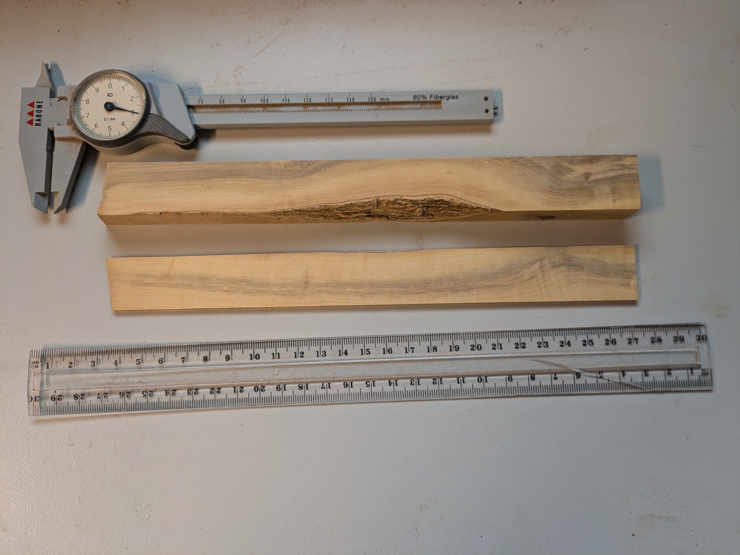
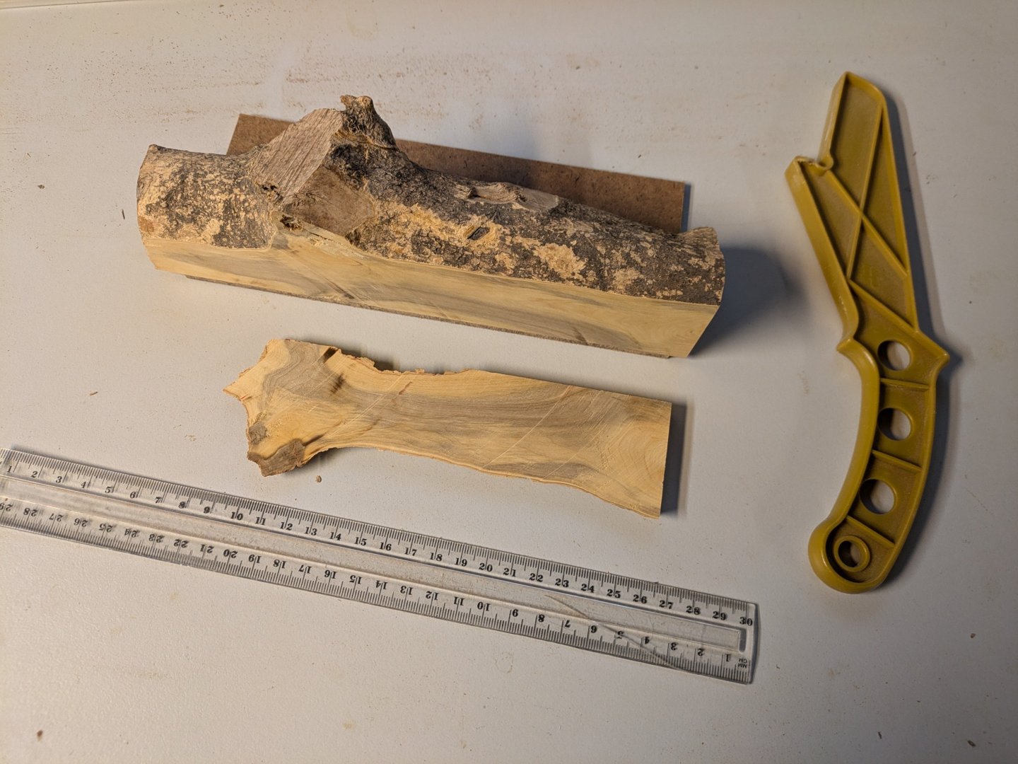
I didn't seal the ends, it was already dry when I got it and it's been kept dry ever since. If it's a fungal stain I think it will be long dead by now, it doesn't seem to have softened the wood. I'll certainly try to quarter saw as much as possible, it doesn't look like it will be a problem to do so. I ended up gluing the block to an offcut of fibreboard, using Weldbond, which is pretty strong. This made it easy to run the block through the saw. For the longer pieces, still to come, I'll use the same technique but I think I'll make a slightly heavier sled using thin ply as the base, and glue a hefty block of pine as a butt stop at the rear of the workpiece to give it more support going into the blade.
-
I agree with Wefalck, it's a superb museum that hasn't lost its way. The models on display are numerous and magnificent. An excellent place to spend a few hours. Or days.
-
Well, I took the plunge and cut a shortish piece off one end, then had a crack at milling it into model-sized lumber. It went surprisingly well, I'm happy (and relieved!) to say. The thin piece was cut to ~3mm thick on the table saw, then brought down to 2.5mm using my little thickness sander. The boxwood seems to have a nice hard, tight grain, mostly the expected yellow colour but with a grey streak through it, quite pretty! It has that unusual honey-like smell that boxwood seems to have when freshly cut. So far, so good!

- 12 replies
-
- 10
-

-
I just found this build log. It's looking great so far! I'm just down the road, in North Rocks. I like the Triumph in your avatar too - we'll have to go for a ride together sometime!