


Tony Hunt
-
Posts
544 -
Joined
-
Last visited
Content Type
Profiles
Forums
Gallery
Events
Everything posted by Tony Hunt
-
Lovely model and and a wonderful piece of research to get all the details right.
-
Welcome Igor. I'm looking forward to seeing your models.
-
An absolute masterpiece. What a pleasure to watch you do your magic, Greg!
- 200 replies
-
- 6
-

-

-
- Transport No. 103
- Hasegawa
- (and 4 more)
-
Aha, thankyou. It is planked on the mold, and then it just lifts off. Not really any tumblehome on the hull. Ingenious!
- 216 replies
-
- 3
-
-
- masterkorabel
- ships
- (and 3 more)
-
I'm fascinated by your patented plastic mold, it looks really effective. But how do you remove the framed hull from the mold so that you can plank it? Can it just be lifted off, or is there some tumblehome?
- 216 replies
-
- 3
-
-
- masterkorabel
- ships
- (and 3 more)
-
Harriet McGregor by Boccherini
Tony Hunt replied to Boccherini's topic in - Build logs for subjects built 1851 - 1900
It's really starting to look shippy, isn't it? Nice save on the mizzen top. -
It might be possible to get a more comprehensive response than that one, Steven, but I'd be surprised if it happens! Awesome work.
-
We need an update, Valeriy! 😀
-
It's a very nice model, well worth the time and effort for a good restoration. A very interesting and unusual subject, and it looks to have been well made. I agree that care is needed to avoid over-restoration. The deck is most unusual. Is it really paint? It looks like some kind of adhesive film that has a deck printed on the upper surface, that has now cracked and delaminated from the brass underdeck. I agree with Roger that it might be best to do as little as possible other than preserve what is left.
-
Apologies for the thread drift Richard! Valeriy and I have taken this off-line, so we can now return to the scheduled program - your fine model of the SS Tamahine. It's looking really impressive.
-
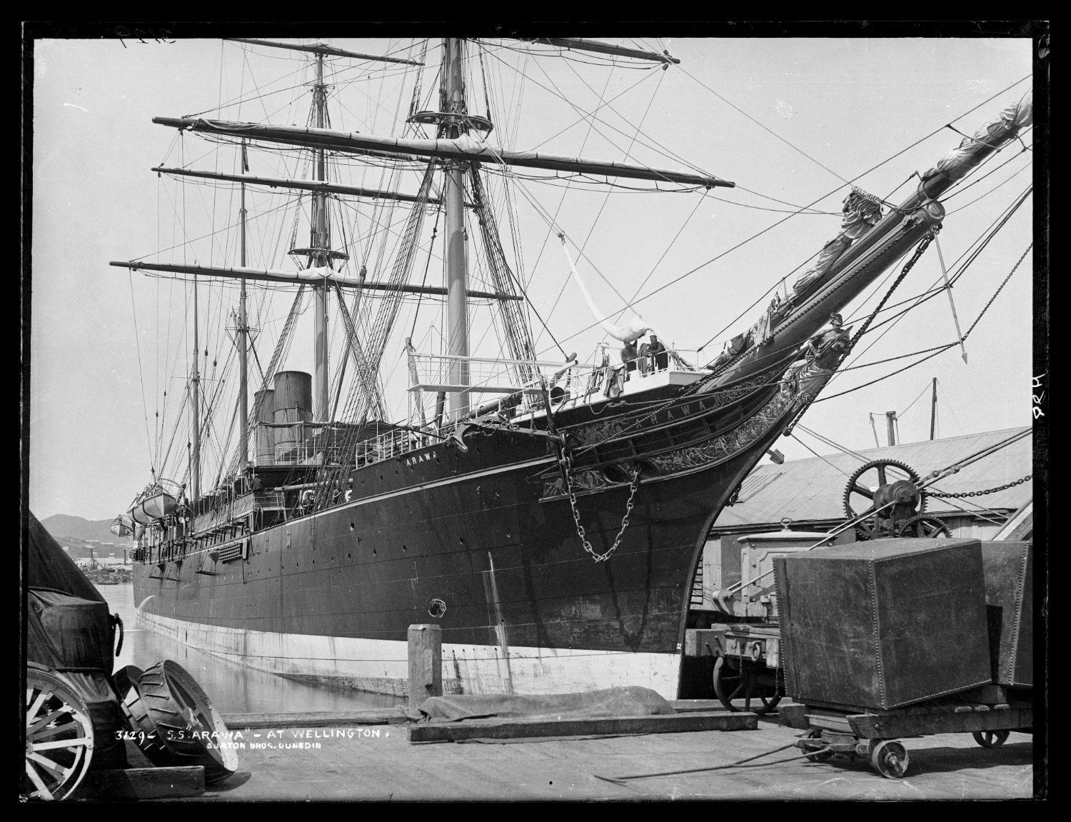
Hello Valeriy SS ARAWA and TAINUI really were magnificent steamers, claimed to be the most beautiful ships in the world at the time. The plans for these ships are held at the National Maritime Museum in Greenwich. They also have the builders half-model (in a mirrored case) although unfortunately it has suffered some damage, possibly during WW2. It's in storage, not on display. The plans (at 1:48 scale) are quite complete. I obtained copies of them (at considerable cost) for my father, who wanted to build a model of ARAWA. He started but didn't get far before he passed away, aged 90. The only problem with the plans are that the lines plan sheet is badly deteriorated and can't be copied. I got some photos taken and have redrawn them to correct for all the distortions caused by curling paper and parallax error from the photography. Please feel free to PM me if you're interested. Regards Tony

.thumb.jpeg.7acc42a8ea4f4861a0096adde2e8b422.jpeg)
-
I'm curious how you made the grommets. Are they just paint dots that are then drilled through? They look really good, anyway!
-
There hasn't ever been a writer who didn't benefit from a good, hard editing! It's been fun following along your voyage of discovery with Glory, great to see the NRJ has recognised the significance of your work.
-
Just use more glue! 😀
-
HMS Renard 1872 by Draque - 1/24 - POF
Tony Hunt replied to Draque's topic in - Build logs for subjects built 1851 - 1900
That looks pretty good to me. In general, when a draughtsman is preparing a lines plan from measurements taken off an existing hull (or even a half model), as I suspect is the case for these drawings, then the station spacing is usually (but not always!) arrived at by divided the length of the hull into x number of even spaces (for a ship this size, usually about ten or twelve stations), without reference to the actual frame spacing. The number of stations is usually determined by what is required to properly define the 3-dimensional shape of the hull. The shipwrights would then use the plans to loft out the frames, and usually it was the shipwrights that made the decisions about practical matters such as frame spacing, scantling and planking sizes etc, with reference to the various framing standards put out by classification agencies such as Lloyds. This would often be specified in the building contract, and this may be available as the author of the book about Cuthbert seems to have unearthed a lot of the original business papers. It might be worth contacting him and asking. A lot of these old Royal Navy documents are still around in dusty old archives somewhere! -
HMS Renard 1872 by Draque - 1/24 - POF
Tony Hunt replied to Draque's topic in - Build logs for subjects built 1851 - 1900
Fighting warships were usually pretty close-framed, but for a lot of commercial vessels the framing was often "room and space", where the gap between the frames more-or-less matches the width of the frames. I'm guessing RENARD and her sisters would be more likely to be framed room and space, even though they were built for the RN they weren't really fighting ships intended for action in naval battles. So in the case above, if the frames are 10 inches moulded the space between would also be 10 inches. -
HMS Renard 1872 by Draque - 1/24 - POF
Tony Hunt replied to Draque's topic in - Build logs for subjects built 1851 - 1900
You're welcome, I enjoy a bit of ship research! I think you'd have to go in to the library at the Australian National Maritime Museum to see the journal, it doesn't appear to be digitised. They're very helpful people, I've been there often. In an interesting twist, it turns out ETHEL wasn't built by Cuthbert, but by another well-known Sydney shipbuilder, Daniel Sheehy: The schooner Ethel, built by Mr Sheehy at Woolloomooloo Bay, has been purchased by the Imperial Government, and will be armed and fitted as a gunboat, for the purpose of cruising among the islands. The Sydney Morning Herald, Fri 16 Aug 1872, Page 4, SHIPS' MAILS. From The Sydney Morning Herald, Fri 19 Apr 1872, Page 4, ROYAL MAIL NOTICE, it appears she was launched in April 1872. There is a nice picture of Sheehy's yard on Flickr, with the steam schooner Llewellyn ready to be launched, in 1874. The background action is interesting! -
HMS Renard 1872 by Draque - 1/24 - POF
Tony Hunt replied to Draque's topic in - Build logs for subjects built 1851 - 1900
You might find this interesting too: https://issuu.com/anmmuseum/docs/signals136_pages/s/13338415 -
HMS Renard 1872 by Draque - 1/24 - POF
Tony Hunt replied to Draque's topic in - Build logs for subjects built 1851 - 1900
Although these photos lack detail they are nicely broadside-on and far enough away that parallax error is trivial, so they will be good for a number of purposes for your model, such as scaling the lengths and angles of the rig. -
HMS Renard 1872 by Draque - 1/24 - POF
Tony Hunt replied to Draque's topic in - Build logs for subjects built 1851 - 1900
Hi Michael I wouldn't buy Bastock's book just for the photos. The original from the Harry O'May collection are available on-line at the Maritime Museum of Tasmania (see post above), while the picture of the CONFLICT from Bastock's collection is available on-line at the Australian War Memorial https://www.awm.gov.au/collection/C237572, a low-res copy is below with CONFLICT (in Sydney Harbour c1875) on the left. I wish I had your skills in CAD drawing. I've been trying to teach myself using TurboCAD but it's proving to be a losing battle!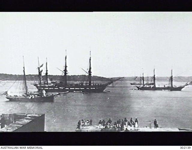
-
HMS Renard 1872 by Draque - 1/24 - POF
Tony Hunt replied to Draque's topic in - Build logs for subjects built 1851 - 1900
This one, notsogood, shows BEAGLE and SANDFLY.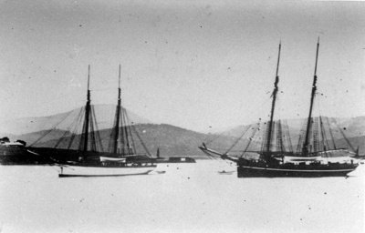
-
HMS Renard 1872 by Draque - 1/24 - POF
Tony Hunt replied to Draque's topic in - Build logs for subjects built 1851 - 1900
Here are ALACRITY and BEAGLE, taken at anchor in Hobart. https://ehive.com/collections/3906/objects/618746/ships-of-the-australia-station-viewed-from-castray-esplanade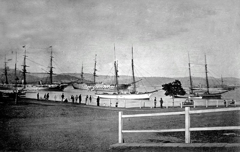
-
HMS Renard 1872 by Draque - 1/24 - POF
Tony Hunt replied to Draque's topic in - Build logs for subjects built 1851 - 1900
Hi Michael I love your project! As a Sydneysider I too have a strong interest in the ships that were built here or sailed from here, and RENARD (or any of the blackbirding flotilla schooners) is a great choice. I didn't know the plans were available, nice work finding them. The plans themselves are interesting. They show a hull with a slight clipper bow, so presumably they are the plans for ALACRITY, originally ETHEL, which it appears was purchased by the Navy rather than built for them specifically like the other four schooners. I wonder who drew these plans? I assume ETHEL was designed in Sydney by Cuthbert or one of his colleagues*, so perhaps these plans ended up with the Navy (and thus in the collection at the NMM) as part of the process for reviewing the design prior to ordering the next four schooners in the series? There are poor photos of ALACRITY, BEAGLE and CONFLICT at anchor in Sydney Harbour on pages 58 and 59 of John Bastock's book Ships on the Australia Station. It might be possible to track down the originals, the images of ALACRITY and BEAGLE are credited to Mr H. O'May (presumably the Tasmanian maritime historian Harry O'May https://adb.anu.edu.au/biography/omay-henry-harry-11304) while the picture of CONFLICT came from Bastock's (https://www.navy.gov.au/biography/mr-john-bastock) own collection. Both these gentlemen passed away long ago and I don't know where these collections ended up, but both were reputable historians so I expect they would have ended up in a public collection somewhere. Re the frame heads question, the usual practice was to end the frames below the deck and put stanchions between the frame to carry the bulwark planking. This reduced the likelihood of fresh water and thus rot getting into the frames. Anyway, great project and I look forward to seeing it progress! Cheers Tony *Perhaps not - it seems a bit unclear who built ETHEL. -
It's looking really good, Håkan. Happy New Year!

.jpeg.1b566d8ae5417a2302f3e9a68e5ab075.jpeg)