realworkingsailor
-
Posts
3,271 -
Joined
-
Last visited
Content Type
Profiles
Forums
Gallery
Events
Everything posted by realworkingsailor
-
 If you’re talking about the part mounted to the left of the smoke stack, it looks pretty much like a turbo generator (for the electric lights). The pipe running back to the cab would be a conduit for the electrical wires, as all the light switches are logically in the cab. Andy
 -
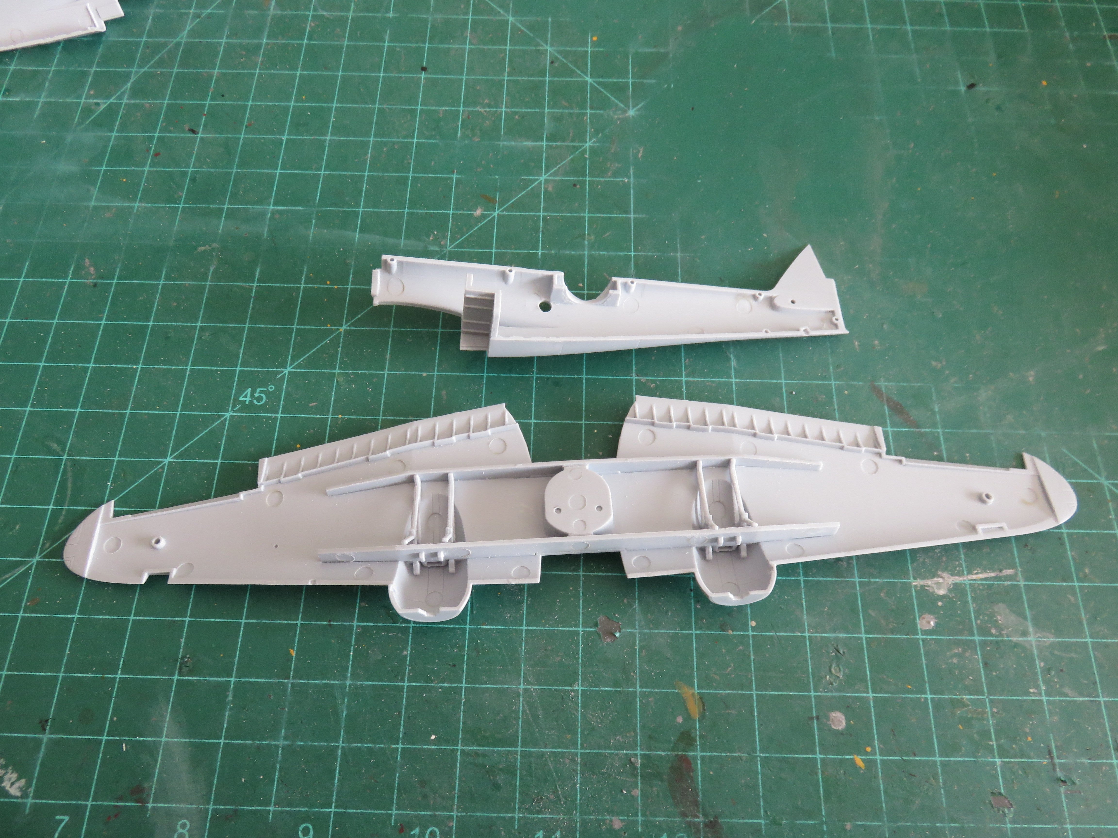
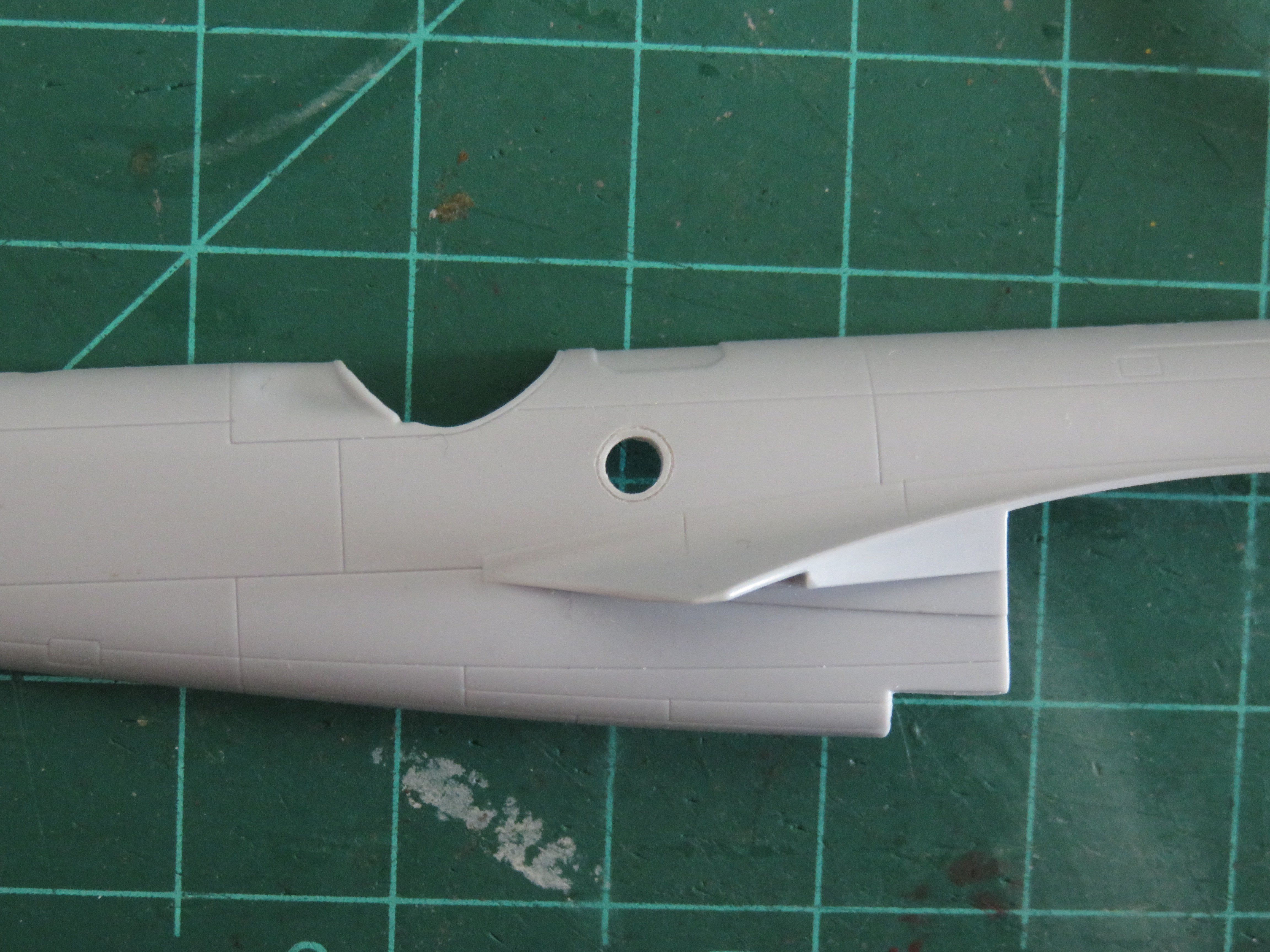
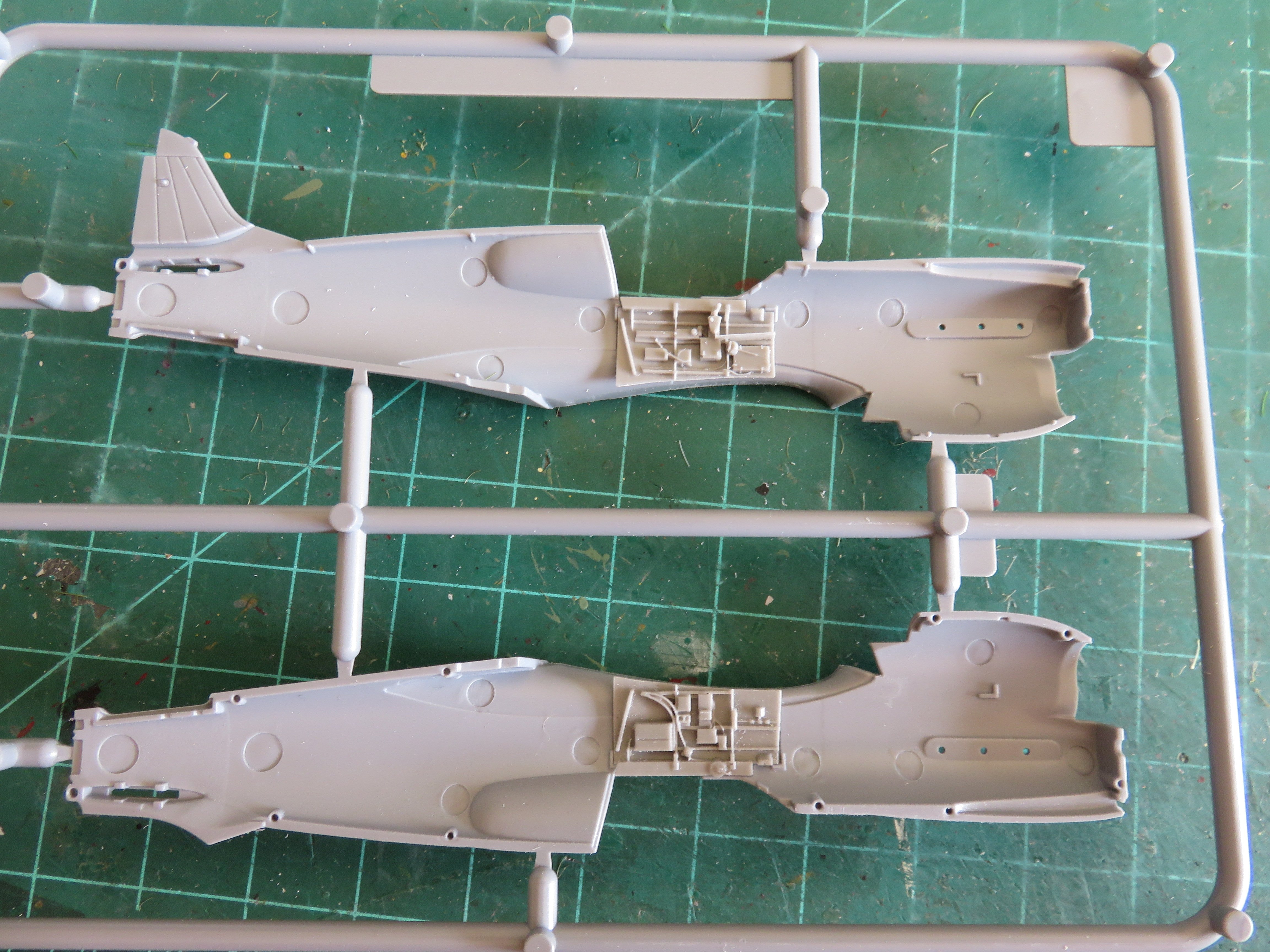
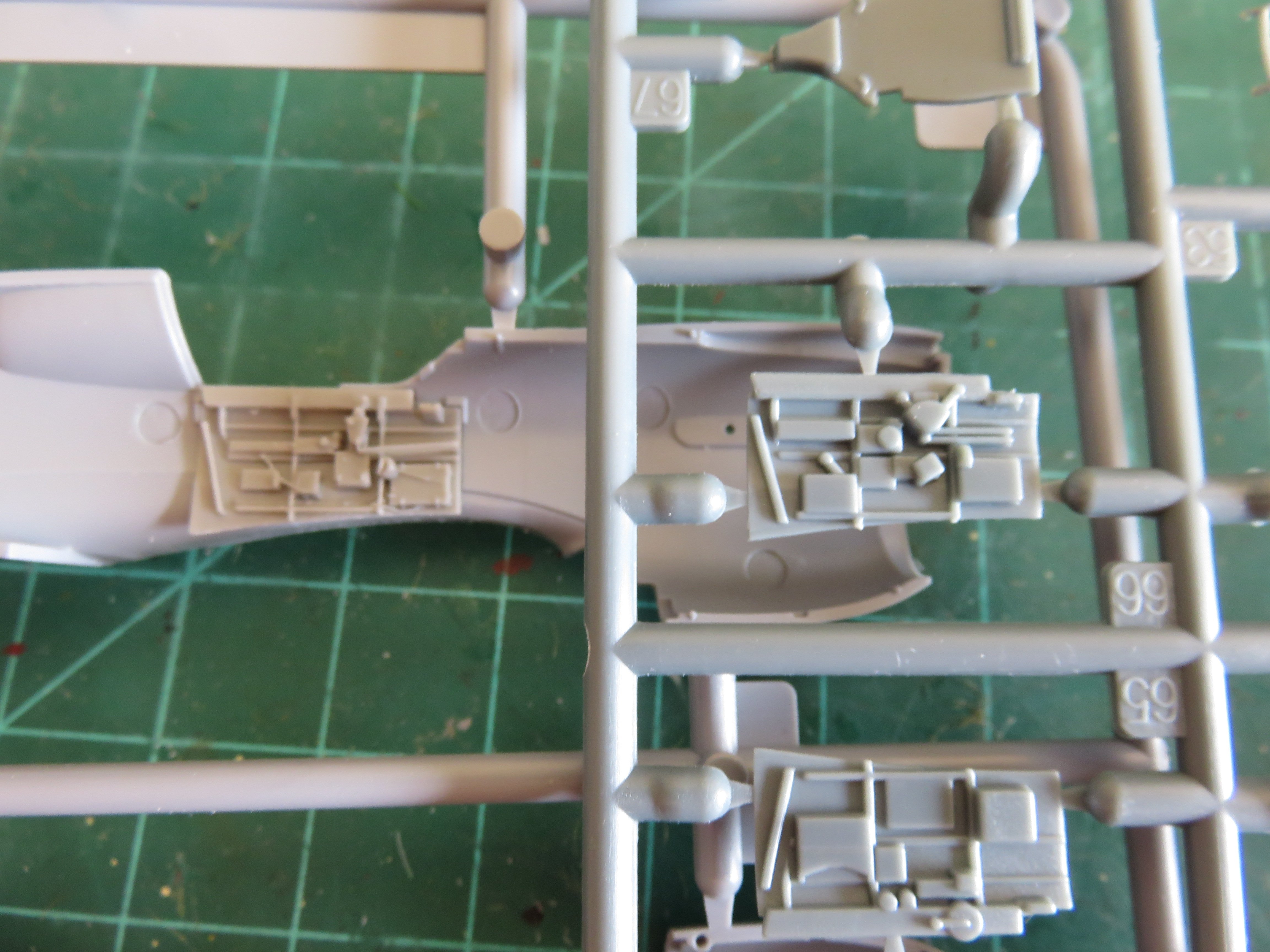
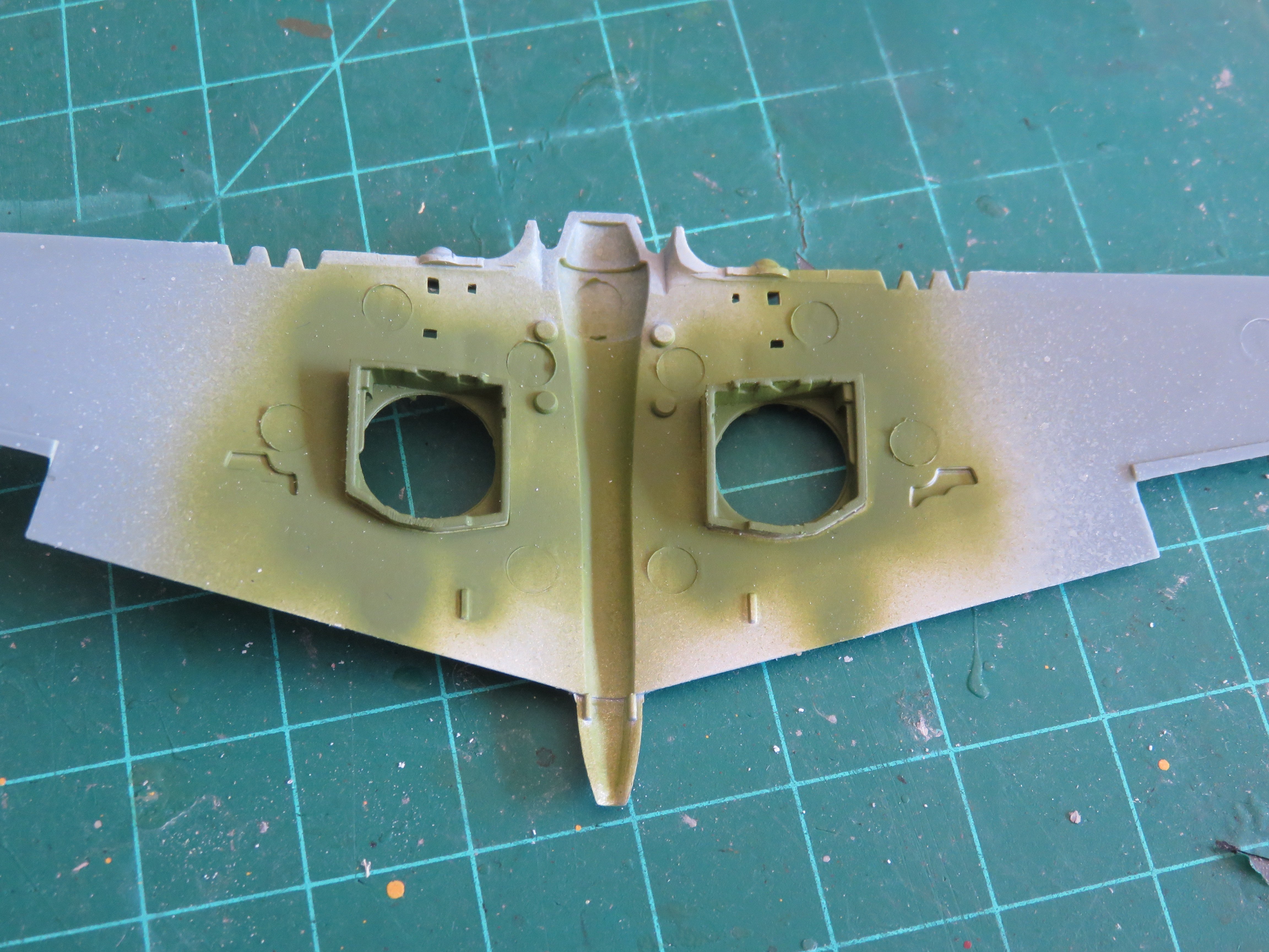
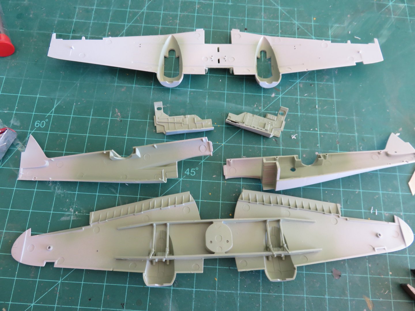
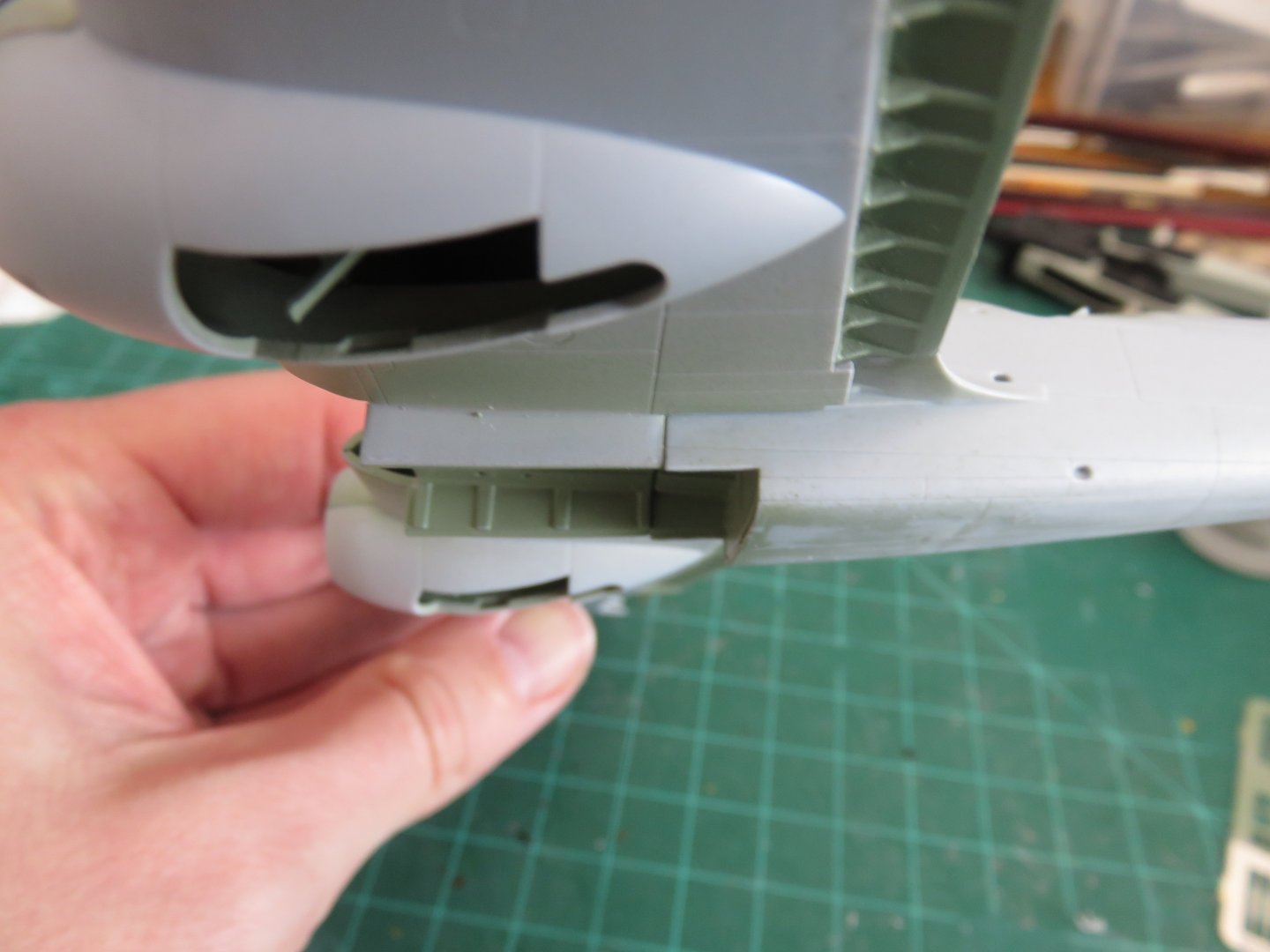
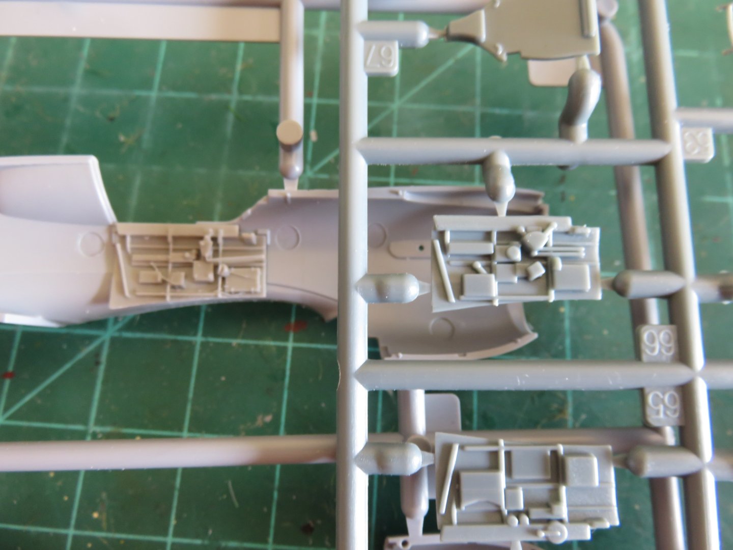
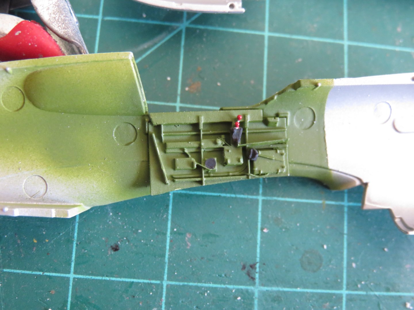
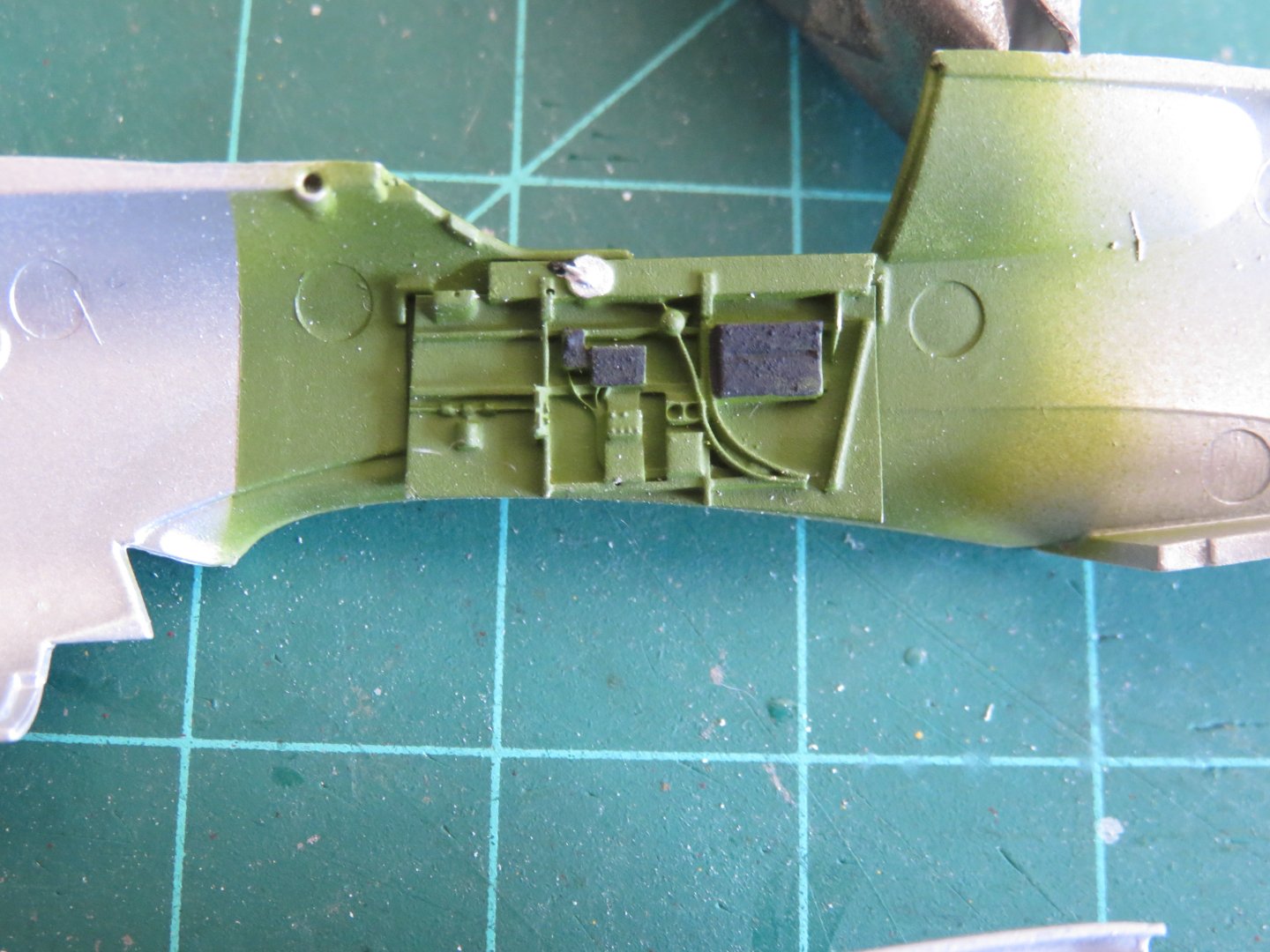
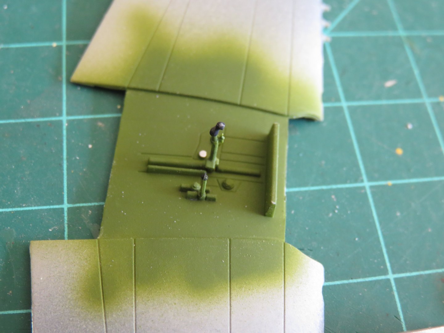
Well, this is proving to be an..... interesting... build. Since my last post I have done a good bit of work. A bit more styrene and filler on the engine nacelles, followed by a coat of primer. I'm fairly happy with the way things are turning out. The primer has revealed a couple of obvious areas in need of further filling and sanding, but overall I think the modifications are looking ok. Since the remaining work seems to be minimal I decided to press on with the first bits of assembly. The kit starts off with the aft fuselage, followed by the landing gear base and wing spar. I assembled about as much as I could, before giving everything a coat of interior green. So far so good, although the kit is definitely beginning to show its age. I think the mould halves are beginning to "bed in" as there are considerable mould seam lines on the edges of parts, in certain areas, that required a fair amount of sanding to clean up. The edges of the wing spars, for example, had a small ridge running down them that had to be removed. I had quite a bit of fun with the green paint. Prior to assembling the aft fuselage halves, I fabricated and installed the windows glazing for the additional porthole. A little canopy glue to hold it in position was needed. The wing halves went together fairly reasonably, however a bit more tape and a few clamps were necessary than on other projects I've build. This seems to be a trend with this kit as I will discuss further on. It took a fair degree of sanding and filing to get the fuselage and wings to sit correctly. Aside from being naturally snug, the fit was less than perfect. there is a small nub that has to sit ahead of the wing spare, in order to allow the front fuselage halves to sit properly. Getting that little nub in position required far more work than it should have. The lower wing halves needed filing to fit, and despite getting every other surface to line up as close as humanely possible, I am left with a very noticeable step in the sides of the bomb bay, as well as a very prominent join line. Ugh... more work. Personally, I think this kit is over engineered. I understand that Airfix wanted to be able to produce both the Mk I and Mk IV Blenheims at a reasonable cost, but I think it would have been a better idea to mould two separate complete fuselages and design a better wing connection than trying this overly complicated, half-backsided approach. The fit here is, honestly, very poor. I am determined to see this build through to completion, regardless, and I hope things begin to improve from here. Thanks for all the kind comments and likes! Andy


- 33 replies
-
- 12
-

-
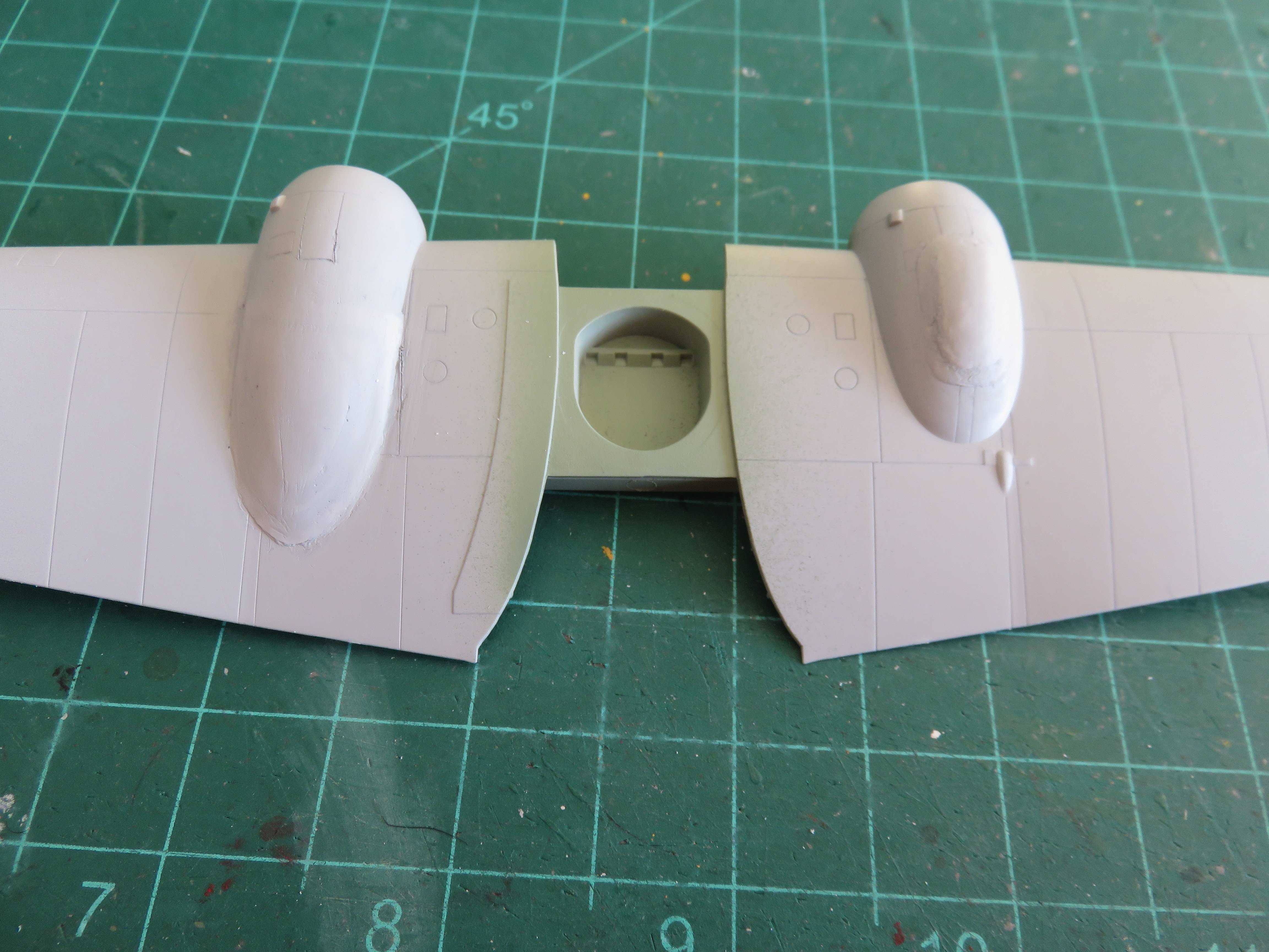
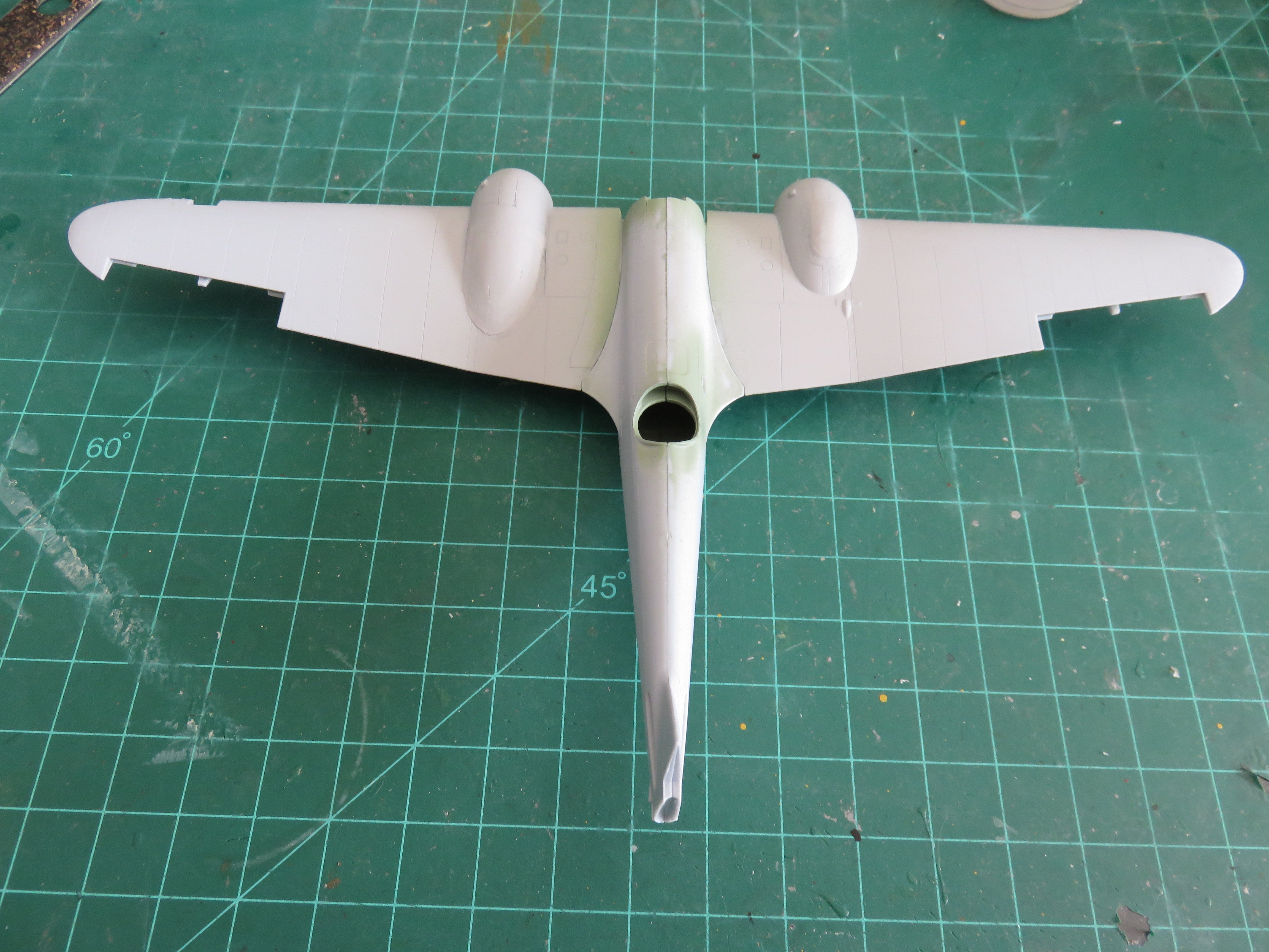
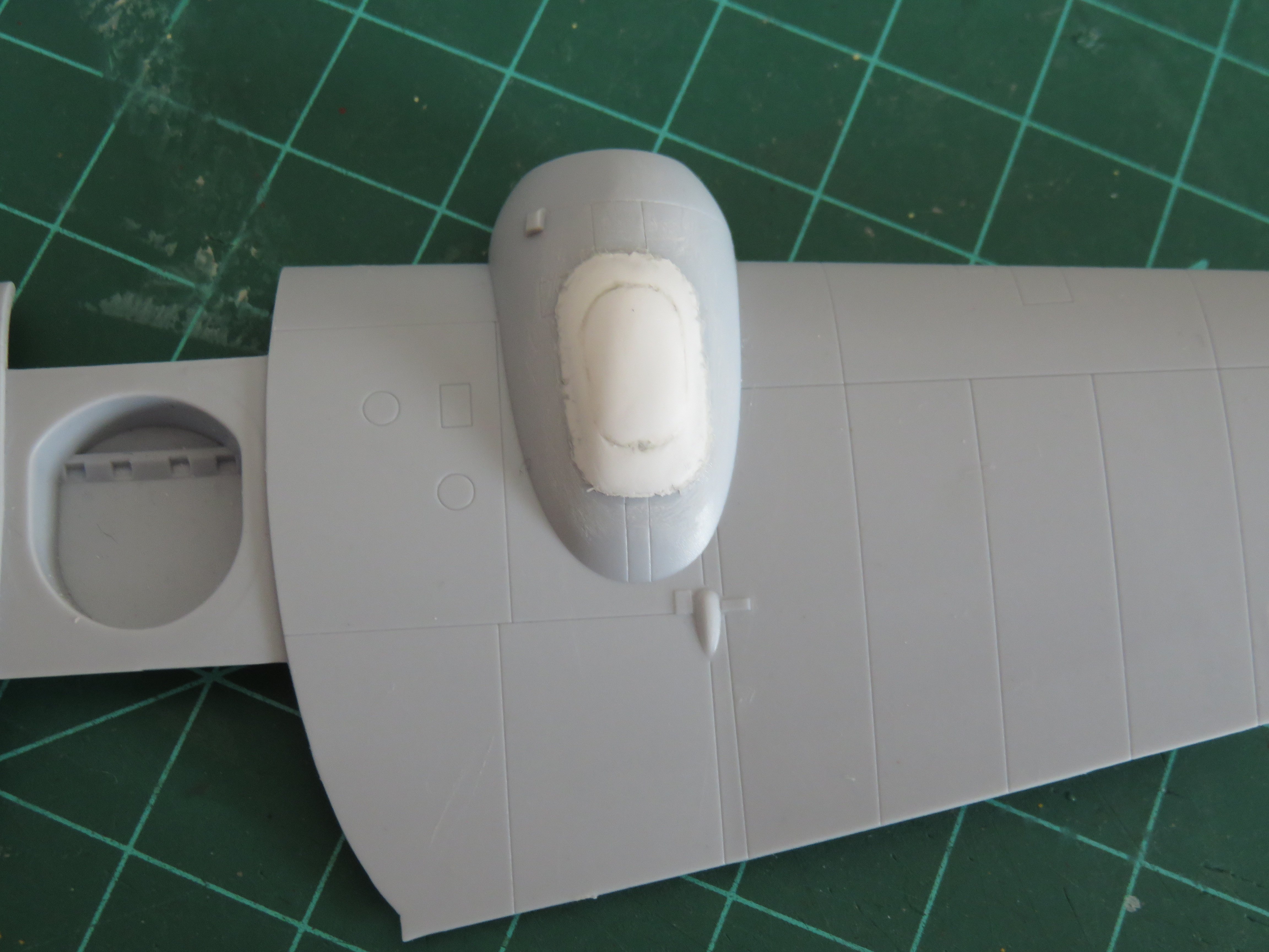
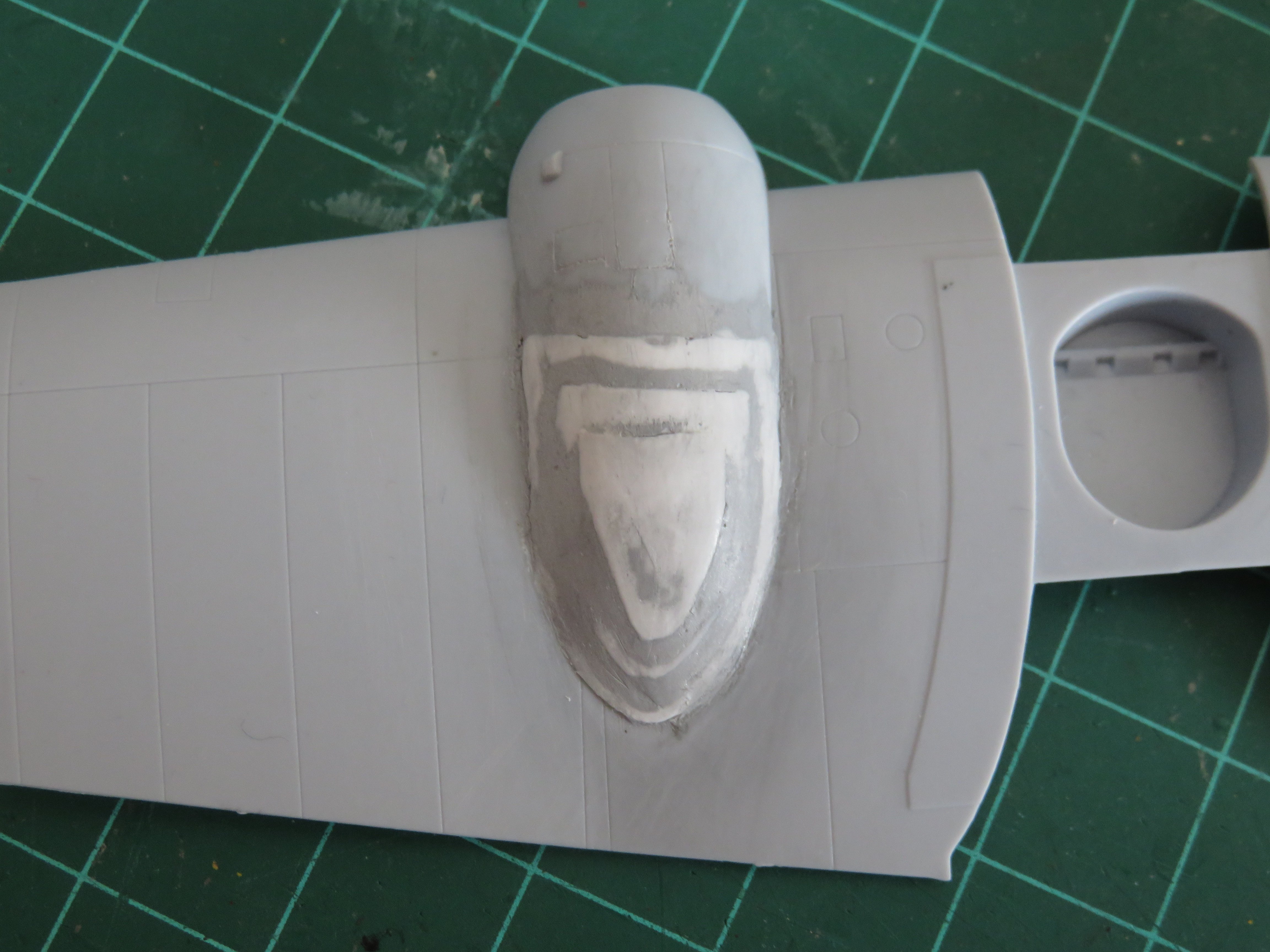
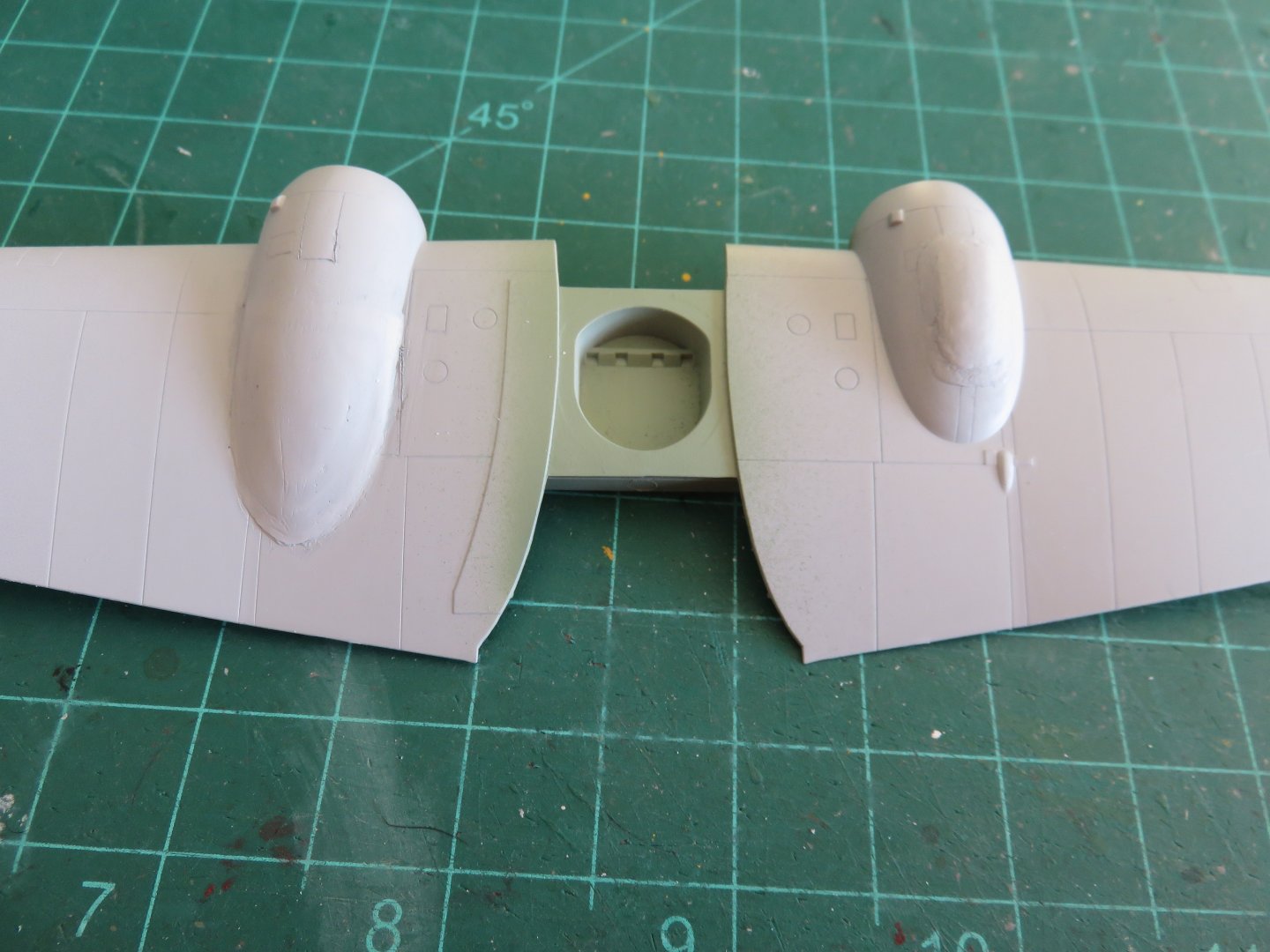
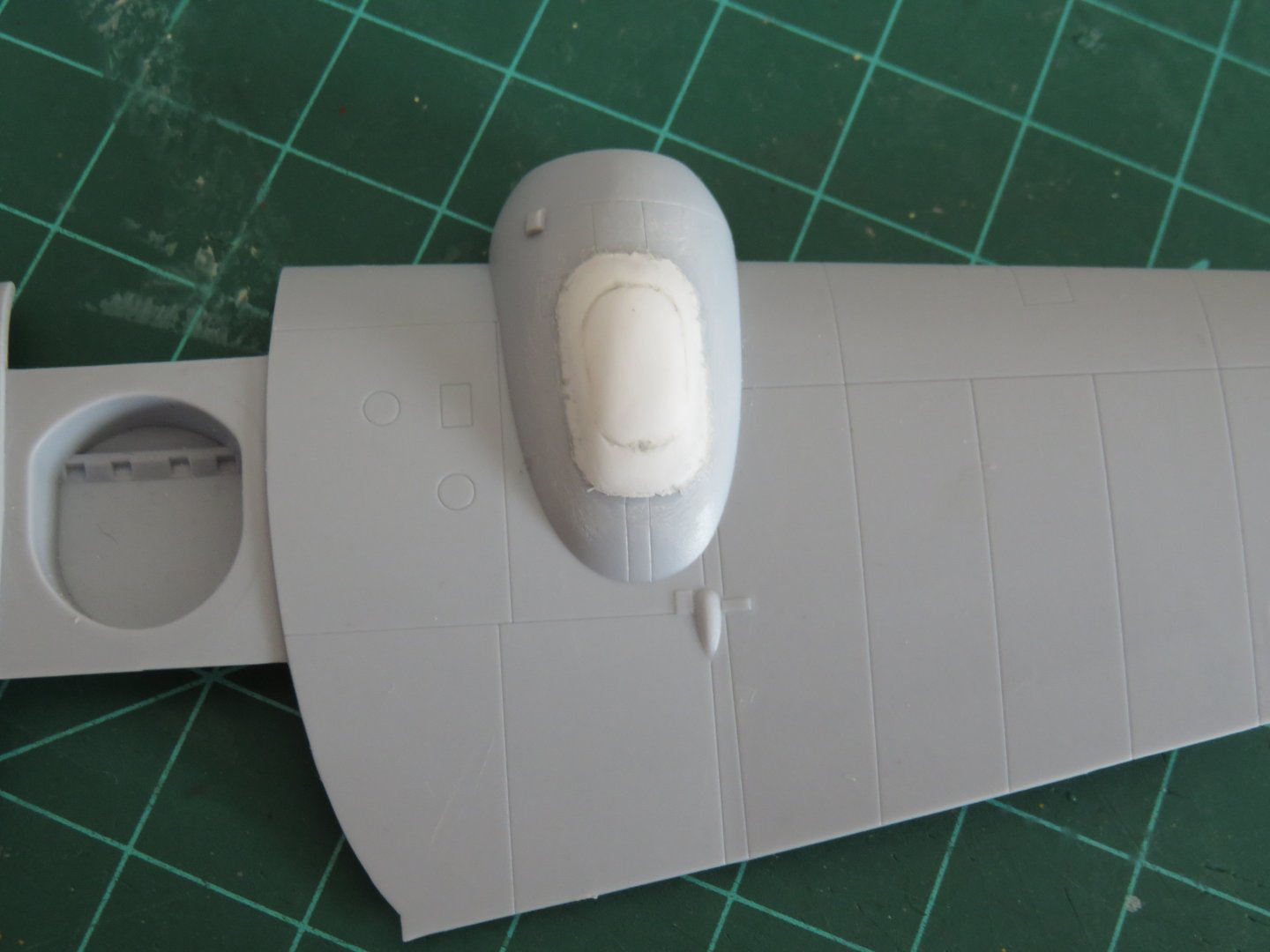
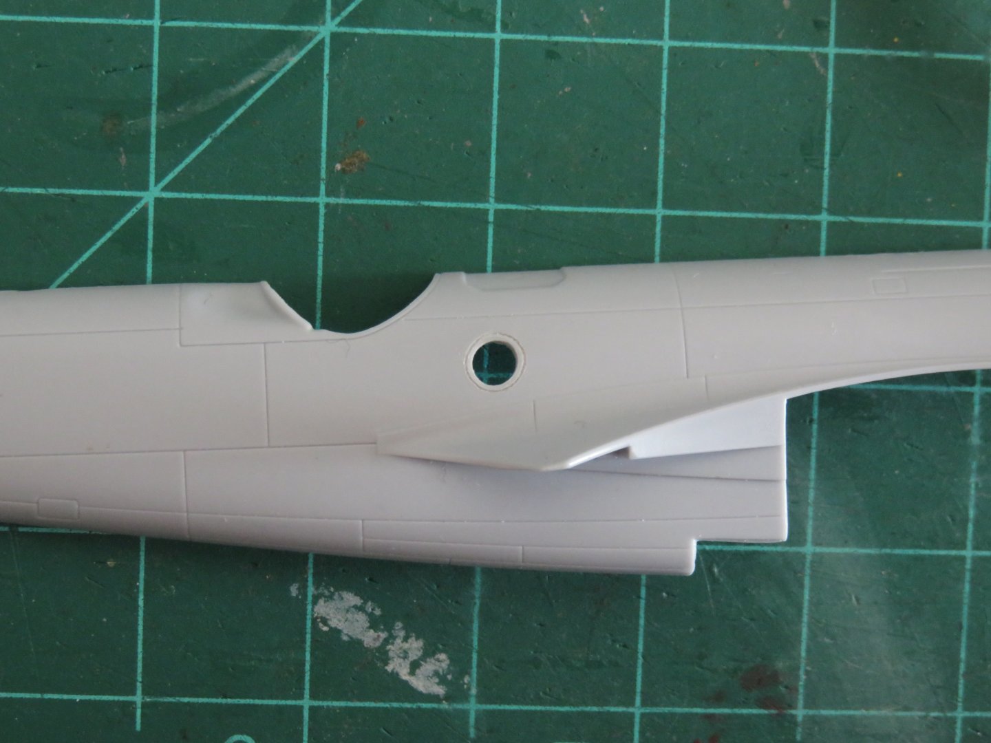
Agreed! Although to give Airfix a little benefit of the doubt, it's perhaps possible that they couldn't get access/permission to scan the sole surviving Blenheim in Finland, and had to go with what they had. But the mistakes on the Mozzie.... 🙄 Time to crack on with the build! Of course my first job has been to work on the modifications to the engine nacelles and fuselage. The latter was fairly straight forward. Although I could find no accurate drawings, I was able to locate the extra window reasonably well using photographs. I first scribed the panel line representing the window frame, before I drilled and filed the window. A little bit of cleanup yet to do, but I'm fairly happy. The engine nacelles were next. Both the port nacelle extension and the starboard hump were created using layers of 0.015" styrene sheet. I started with the starboard side, as this seemed the simpler side to work with. The styrene has been sanded fair, but I think I need to make the hump on this side a little more prominent, so I will probably add one more layer of styrene over the whole thing, then fill and sand to shape. The port nacelle extension was fabricated using three pieces of styrene sheet, cut roughly to shape. It's still pretty rough looking, but some more filler and some careful sanding, and things should begin to look passable. To my eye, at least, the asymmetry is beginning to look somewhat correct for a wartime Bolly. Thanks to everyone for looking in and your "likes" Andy

- 33 replies
-
- 16
-
-
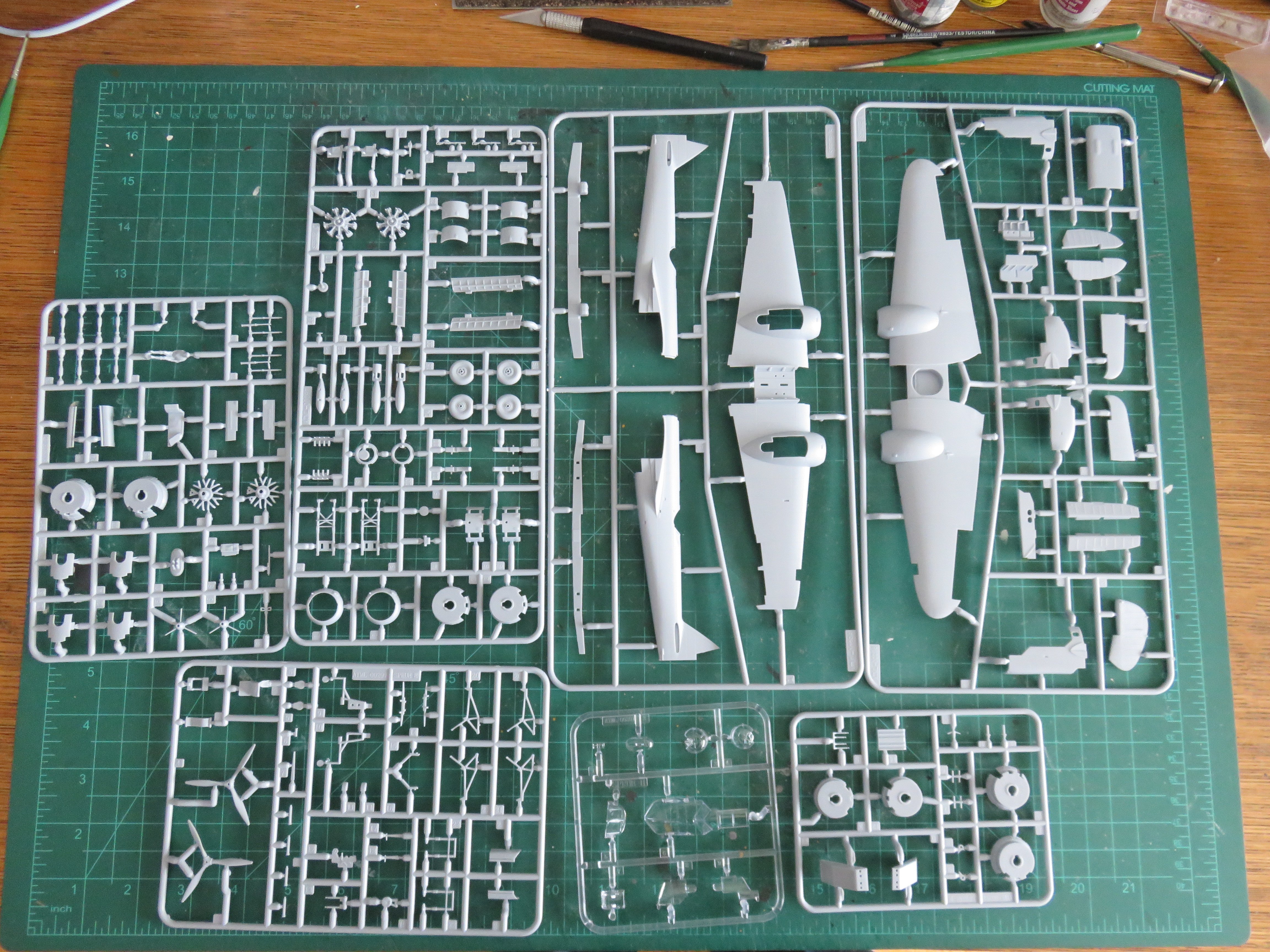
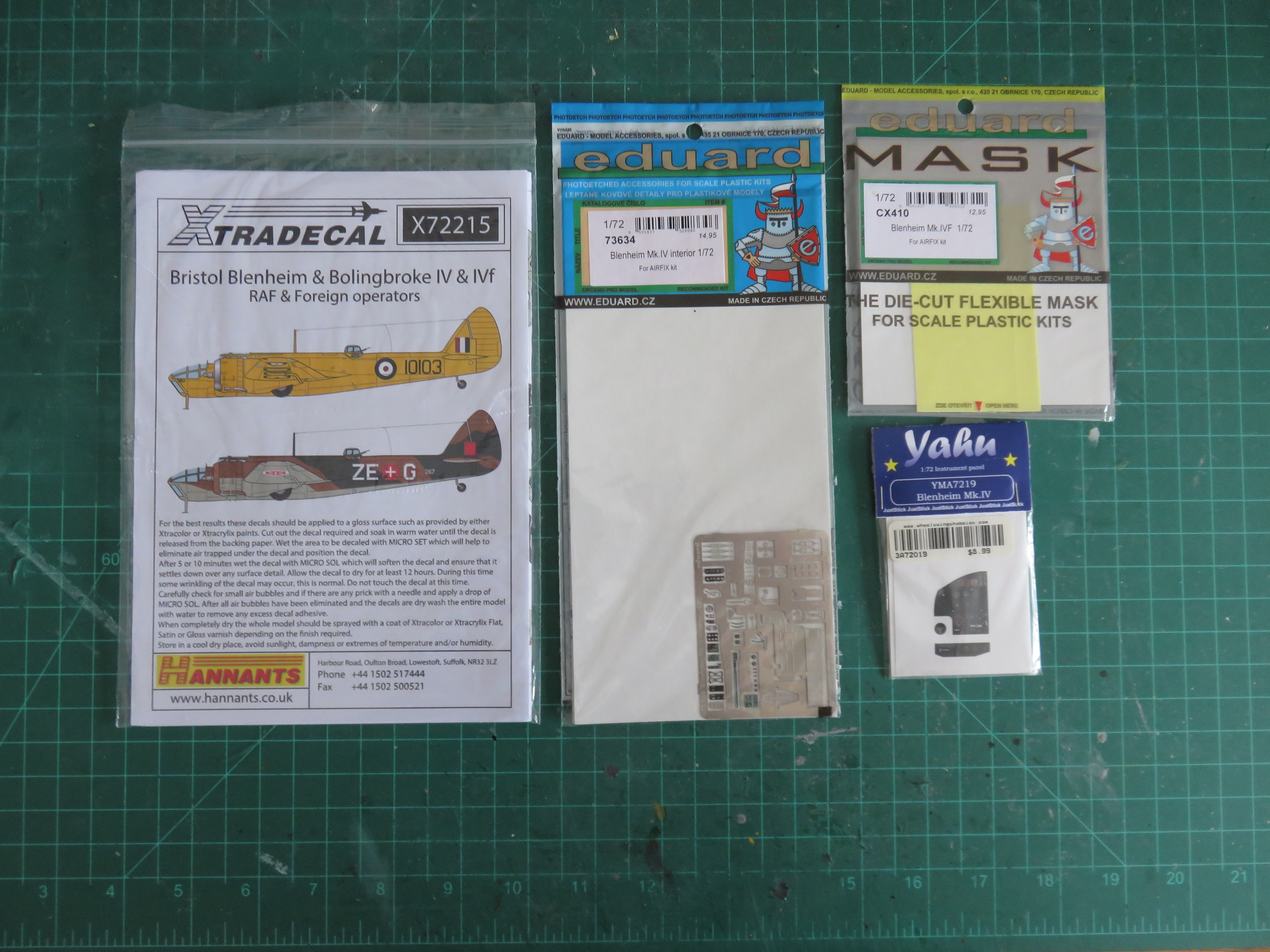
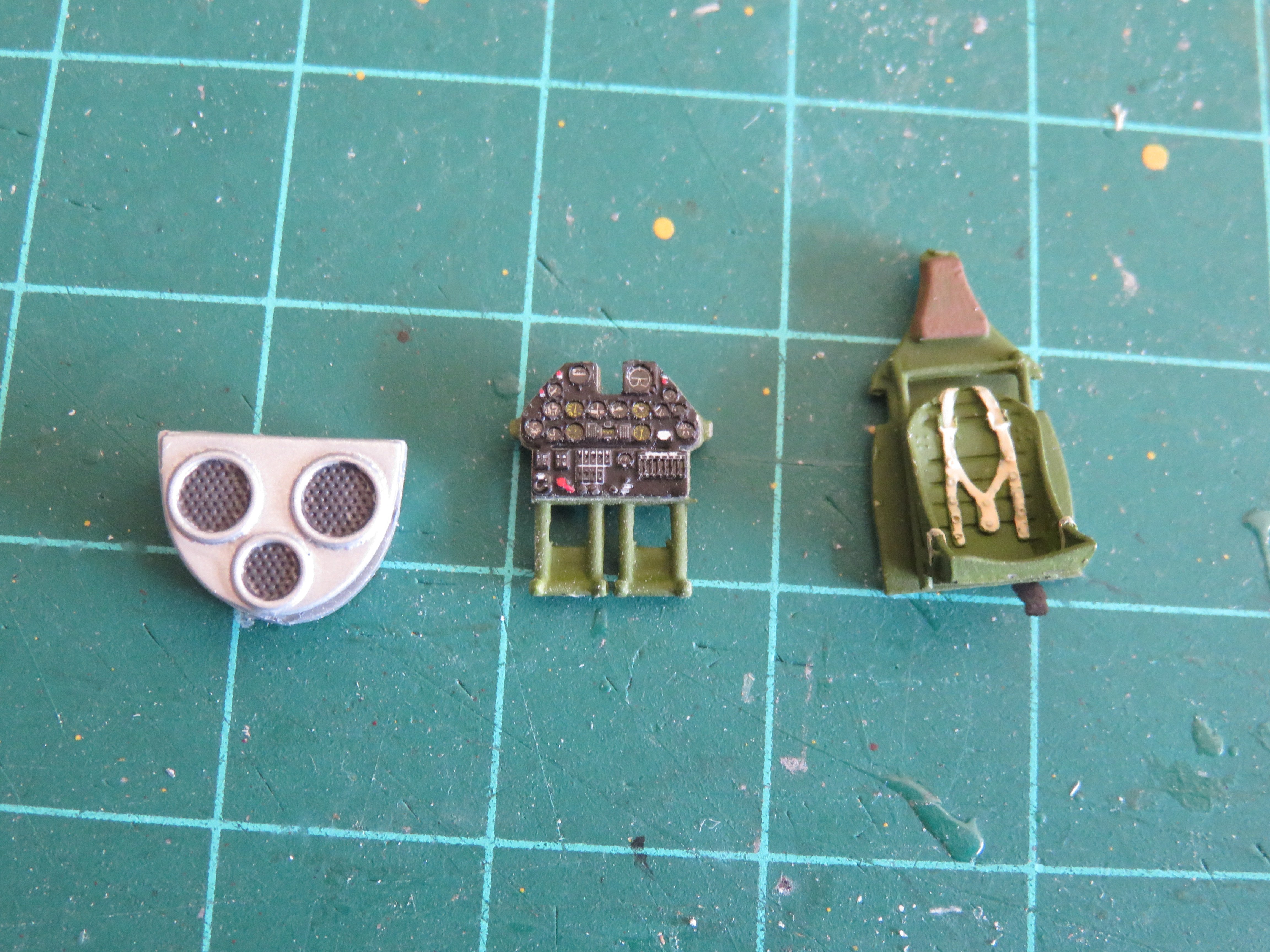
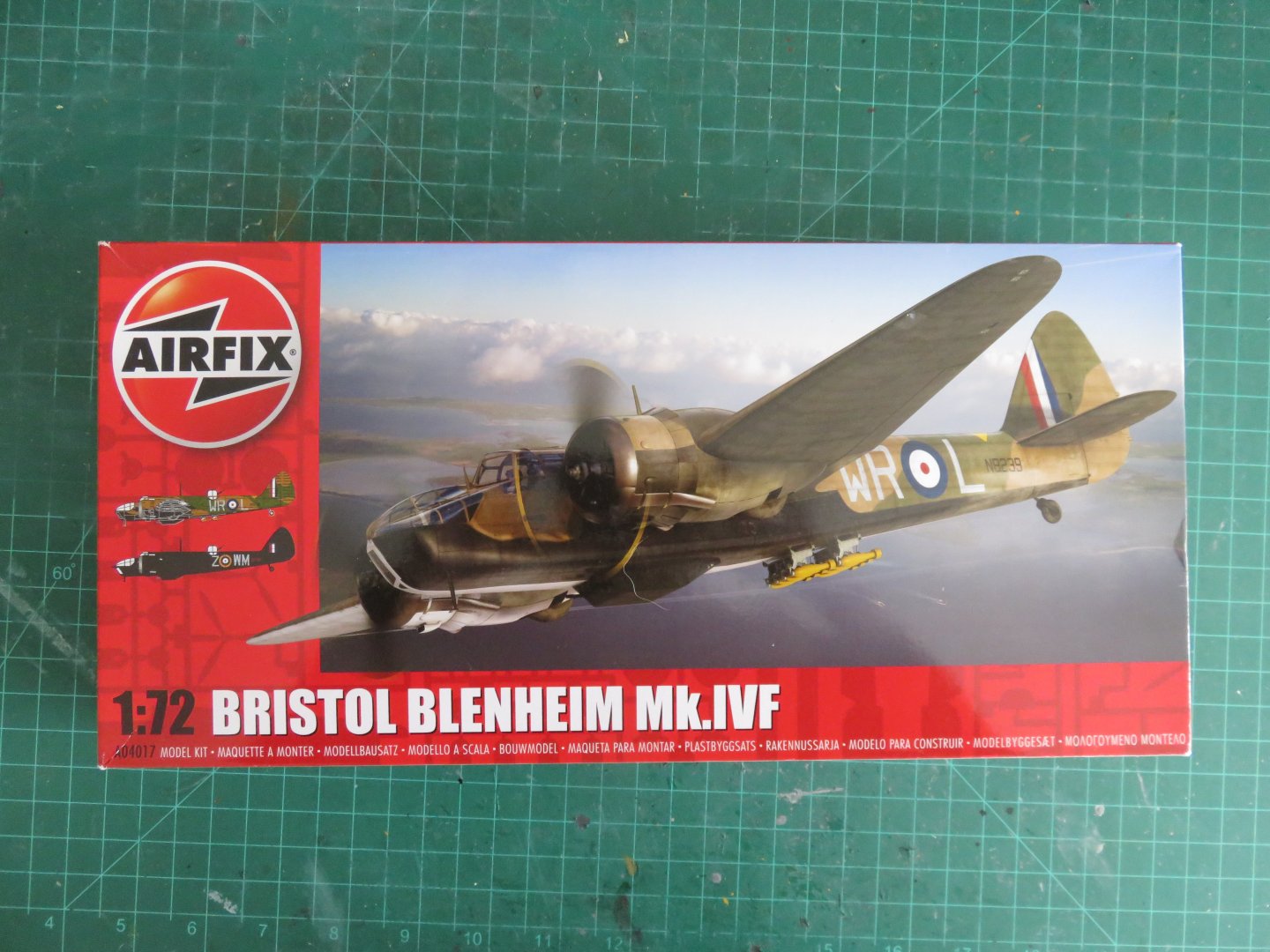
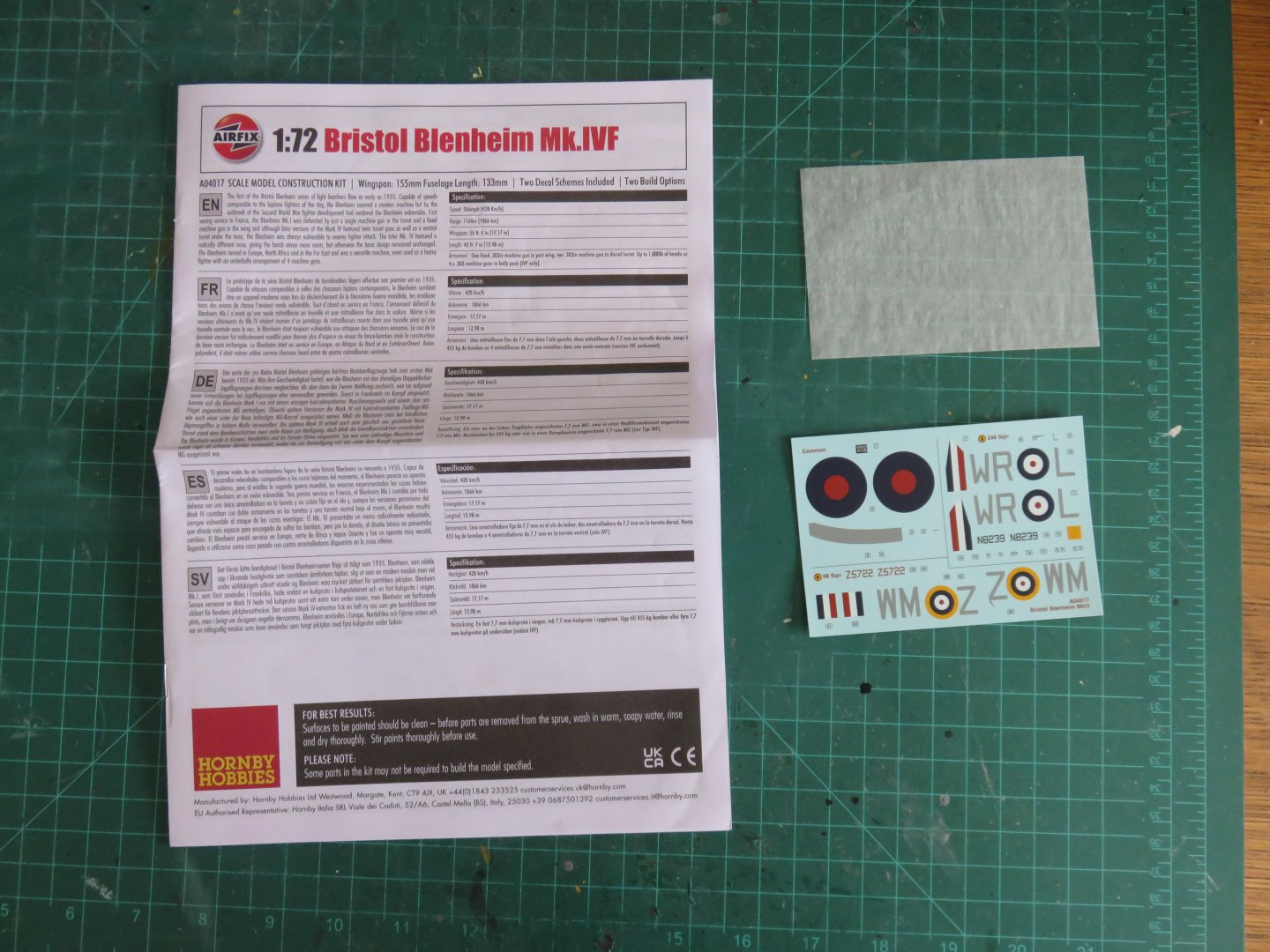
For my next build, I've decided to take on a bit of a challenge (although, one starting with a reasonably simple kit). The Bristol-Fairchild Bolingbroke was a Canadian licence built version of the Bristol Blenheim light bomber by Fairchild Aviation Canada. Originally conceived as a maritime reconnaissance and patrol aircraft, it went on to fulfill other roles, most notably in the Commonwealth Air Training Plan. Of the 626 built, over 450 were built as Bombing/Gunnery/Navigation trainers. The Bolingbroke (or "Bolly") had numerous subtle features that set it apart from its nearly identical stablemate. As it was conceived as a maritime patrol airplane, provision was made for a 4th crew member, fulfilling the duties of the Radio Operator. To provide some light for his workstation, a window was added on the starboard side of the fuselage, just forward of the dorsal turret. As it was designed to operate in colder climates, it could be equipped with anti-icing boots on the wings, it also featured enlarged engine oil heaters. This last feature is only noticeable the starboard side engine nacelle as a beetle-backed hump. The port engine nacelle was enlarged in its entirety to accommodate a dingy, giving the Bolly a distinctly asymmetrical look when viewed from astern. On the Blenheim, the dingy had been stowed in a valise inside the fuselage, requiring the crew to wrestle it out, in the event of ditching. Most other changes were found inside the airplane, such as the instrumentation, although one Bolly was converted to a float plane. Numerous Bolingbrokes survive in museums around the world. Many were sold to farmers after the war. Shorn of their wings, they found new purpose as storage sheds or chicken coops. Many would later find their way into salvage yards, where they remained for many years until local civics groups and enthusiasts "rediscovered" them. Some basic history of the airplane can be found here, and some nice prototype photos can be found in this discussion thread here. The Airfix 1/72 Bristol Blenheim IVF will serve as the basis for my build. Keeping it short and sweet, this kit comes in the usual packaging from Airfix. The plastic is the typical blue-grey fare from Airfix. As this is the Mk IVF variant of the Blenheim, there is an extra sprue with parts specific to that variant, in addition to the basic components for building a Mk IV bomber variant. Pretty much bog-standard instructions and Cartograph decals are included in the kit. As for extras, I've picked up a few odds and ends to help me with this build. The Xtradecal set features lettering for Bolly 10103, in brilliant trainer yellow. I plan to build this version! I've also picked up the Eduard PE Blenheim interior set, as well as the Yahu models instrument panel. While it may seem odd that I've duplicated some things here, the Bolingbroke had duplicate instruments across the entire front of the cockpit. The extra parts should come in useful to model this feature. Finally, a necessary masking set, as this airplane features a ton of glazing, and I don't fancy masking that all by hand. I've begun work on the external modifications, and I will be posting a build update soon. Andy


- 33 replies
-
- 14
-
-
Most likely due to whatever business arrangement the owner has with his supplier. Some small hobby shops aren’t extended credit from suppliers (the owner has to buy his stock from suppliers before they will ship it to him), this would make the retailer the “end user” as far as the supplier is concerned, so any follow-up is the responsibility of the retailer. Andy
-
From what I saw online, and in person, all sales of the affected products was to stop after December 31, and any unsold inventory to be turned in for disposal. There were no bargains to be had, however, prices remained at regular retail rates. Andy
-
So I think the time has come to call this build finished. Hooray! I've added a little light weathering with my usual PanPastel treatment. I've also dry brushed a little silver paint in the odd place to add a little more wear and tear. I'm no expert when it comes to weathering, but a little here and there helps, I think. Thanks to everyone who has been following along and to those who have offered their kind comments and likes, your support is greatly appreciated! Andy


- 53 replies
-
- 17
-
-

-
A small update to end the old year. Major construction has now finished on this build. After some careful consideration, I applied only a few of the kit supplied stencil decals. Most of them are illegible anyways, and many were so small that they more resembled specks of dirt. Assembling the landing gear didn't pose too many challenges. There's a small stabilizing strut that was a bit fiddly, but not impossible. The landing gear bay doors were next. I would strongly recommend to anyone building this kit, to avoid attaching the wheels until the last. This gives the most amount of useable working area to get the smaller parts in place. I replaced the kit supplied wheels with CMK resin alternatives. They look quite a bit better, in my opinion. After assembling the landing gear, it was time to give the plane a layer of Dullcote to seal everything in, and remove the masking from the windshield. The canopy and window inserts were painted separately and then added. Over then next few days, I will add a bit of light weathering. I am contemplating adding a small diorama base as well. Anyway, I have had fun with this kit and would recommend it to anyone who likes P-40s. Out of the box, the detail level is great, and can easily be upgraded with well made aftermarket parts. I expect one more update early in the new year with some final photos for everyone. Until then, thanks to you all for your continued kind comments and likes, and have a Happy New Year! Andy


- 53 replies
-
- 16
-
-
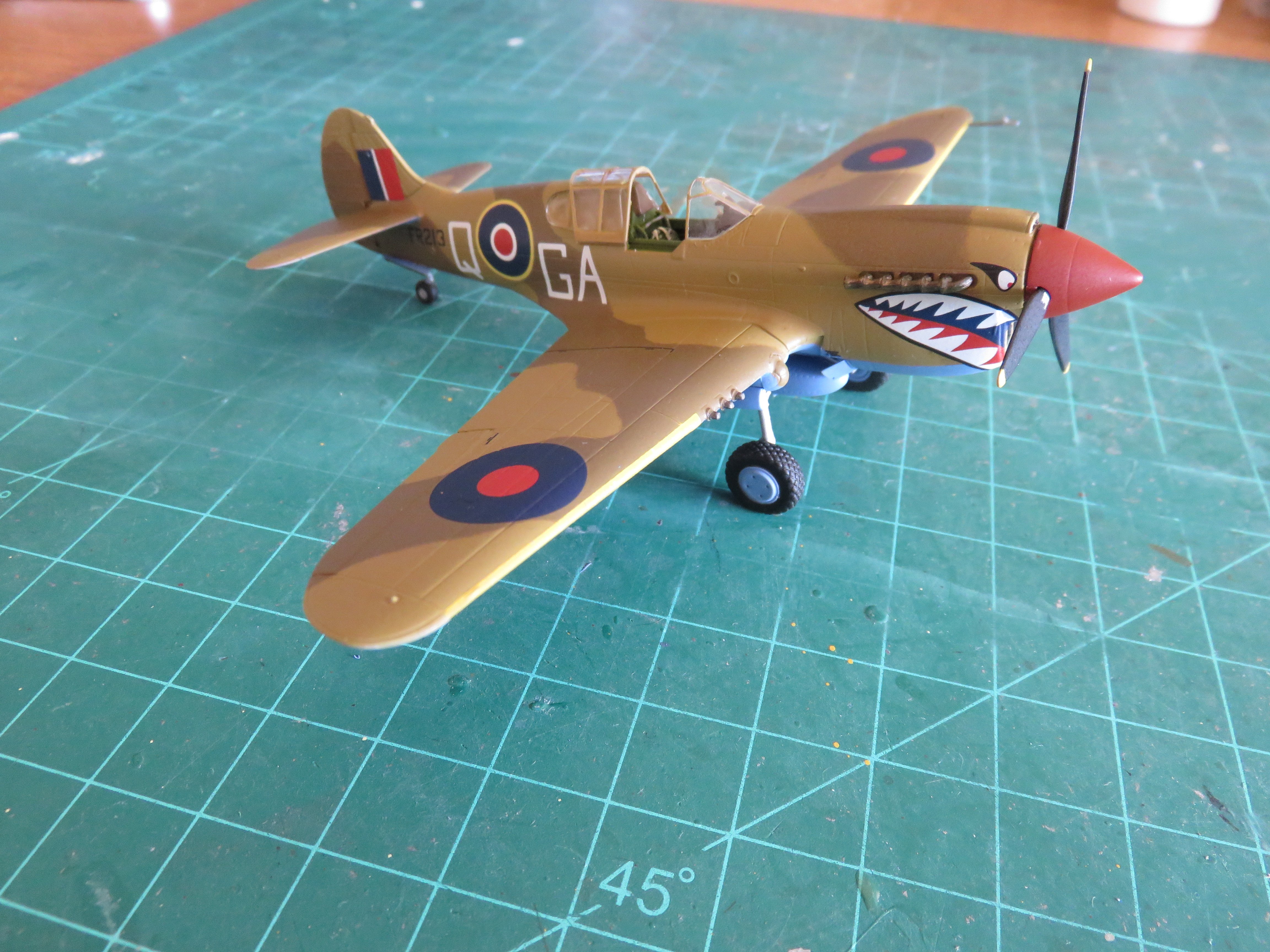
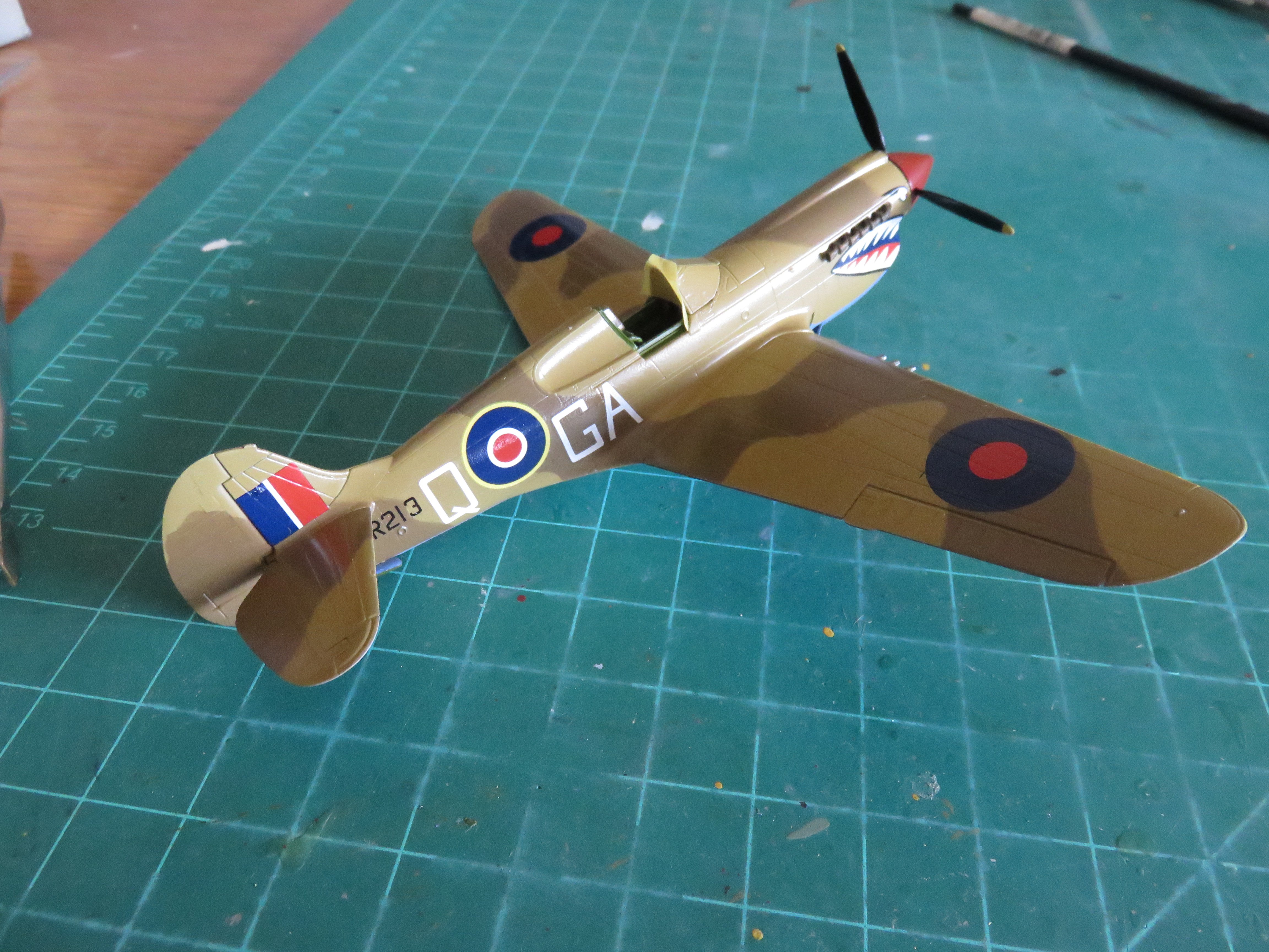
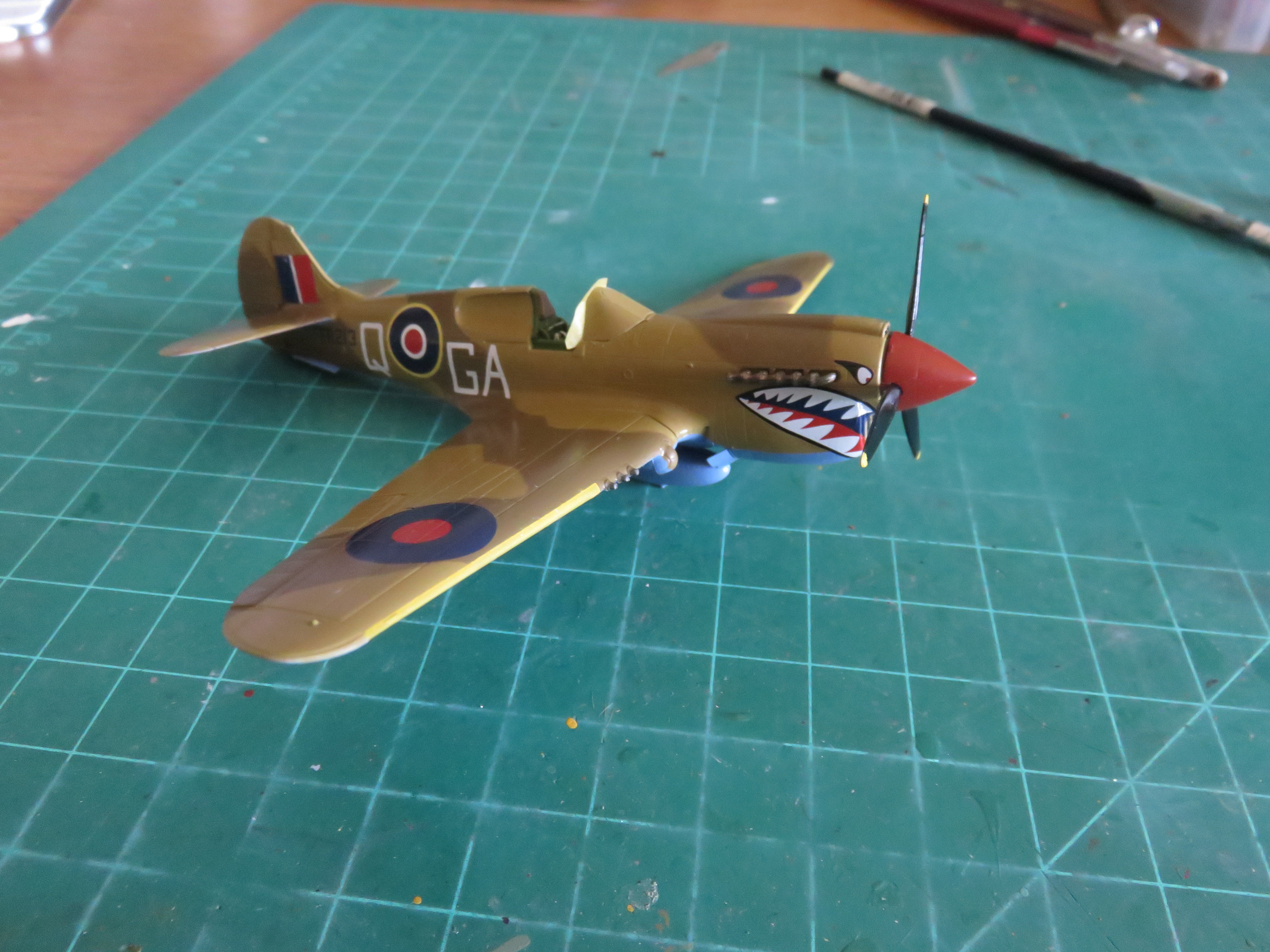
Thanks, everyone, for your kind comments and "likes"! I have a small update to report, as some progress has been made over the last couple of weeks. Most noticeably, the main decals and lettering have been applied! I always like this stage, as it gives the model an identity and some history. Overall, I would rate the DK Decals as being of great quality, clean crisp printing and thin decal film, as well as minimal film around the edges of each decal. The glue they use is somewhat stickier than that used by other decal brands. This means a bit longer of a soak in water, as well as a need to make good use of Micro Set when positioning each transfer. The decals set down quite nicely into the various folds and recesses of the plane without too much difficulty and the use of Micro Sol was not needed in most cases (but I used it anyway, just out of habit, and just in case). The shark mouth proved to be the most trickiest decal to get right, lots of gentle manipulation to get first one side in place, then the second. Thankfully the left and right sides came as two separate decals to make this process about as easy as it could be. As far as any remaining lettering, I'm down to the stencils provided in the kit supplied decal sheet. I am leaning towards sticking to the more prominent ones (like the fuel filler covers), rather than the litany of tiny fine stencils found elsewhere on the airplane. I've also added a couple more important details. The prop and spinner have been added, as well as the engine exhausts. My modification to make the prop spin seems to be working well enough. The remaining canopy parts have been masked and are ready for painting, and the landing gear is coming soon. Given how busy life gets around this time of year, it will take a couple of weeks picking away at things as time permits. I'm not going to be overly ambitious and claim that I'll have everything done by the New Year, but I should manage shortly afterwards. Thanks to everyone for your continued support! Andy

- 53 replies
-
- 14
-
-
Glad to see you back, BE! Looking forward to watching your progress on another masterpiece! Andy
- 332 replies
-
- 2
-
-
- Harpy
- Vanguard Models
- (and 1 more)
-
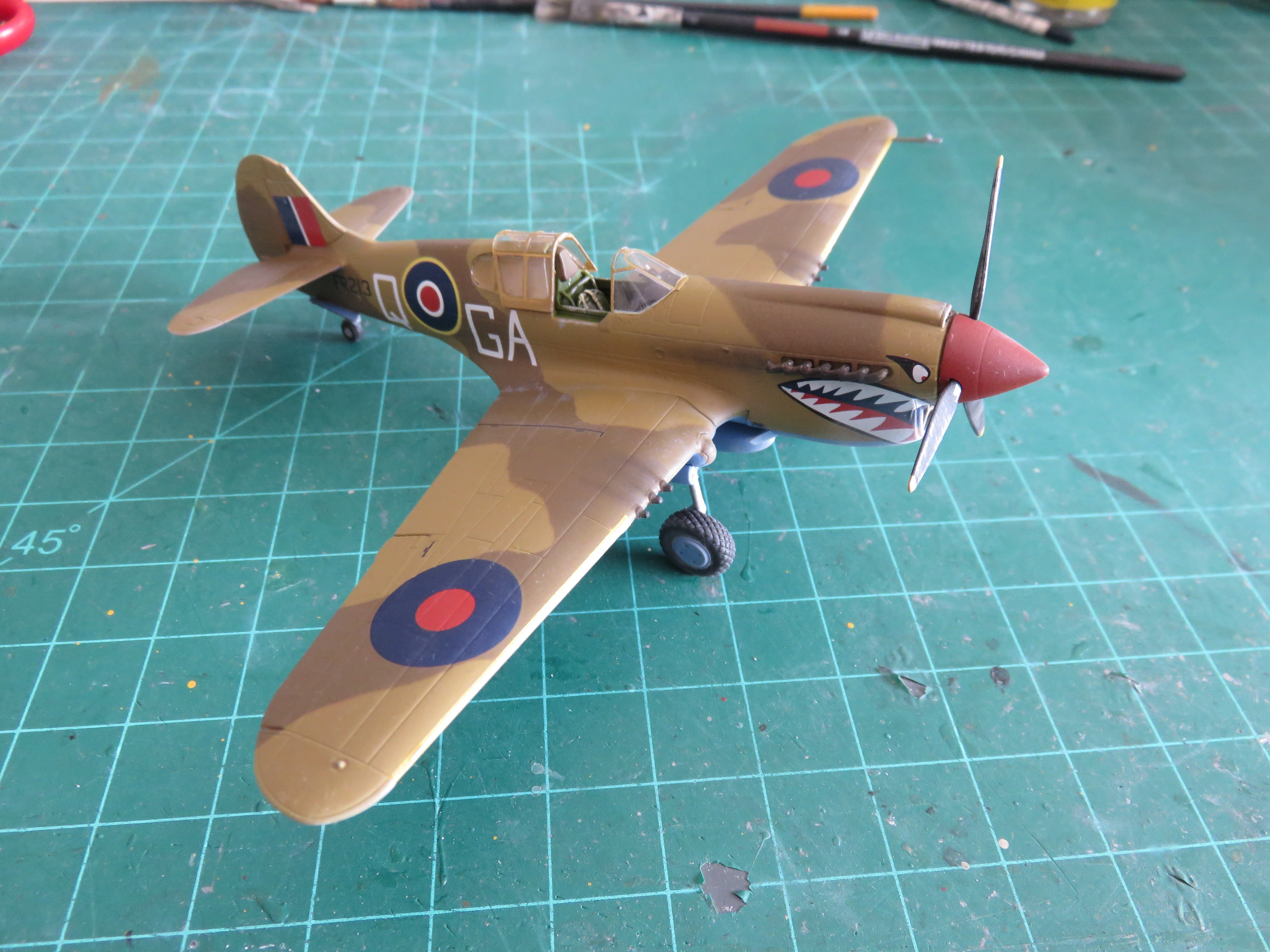
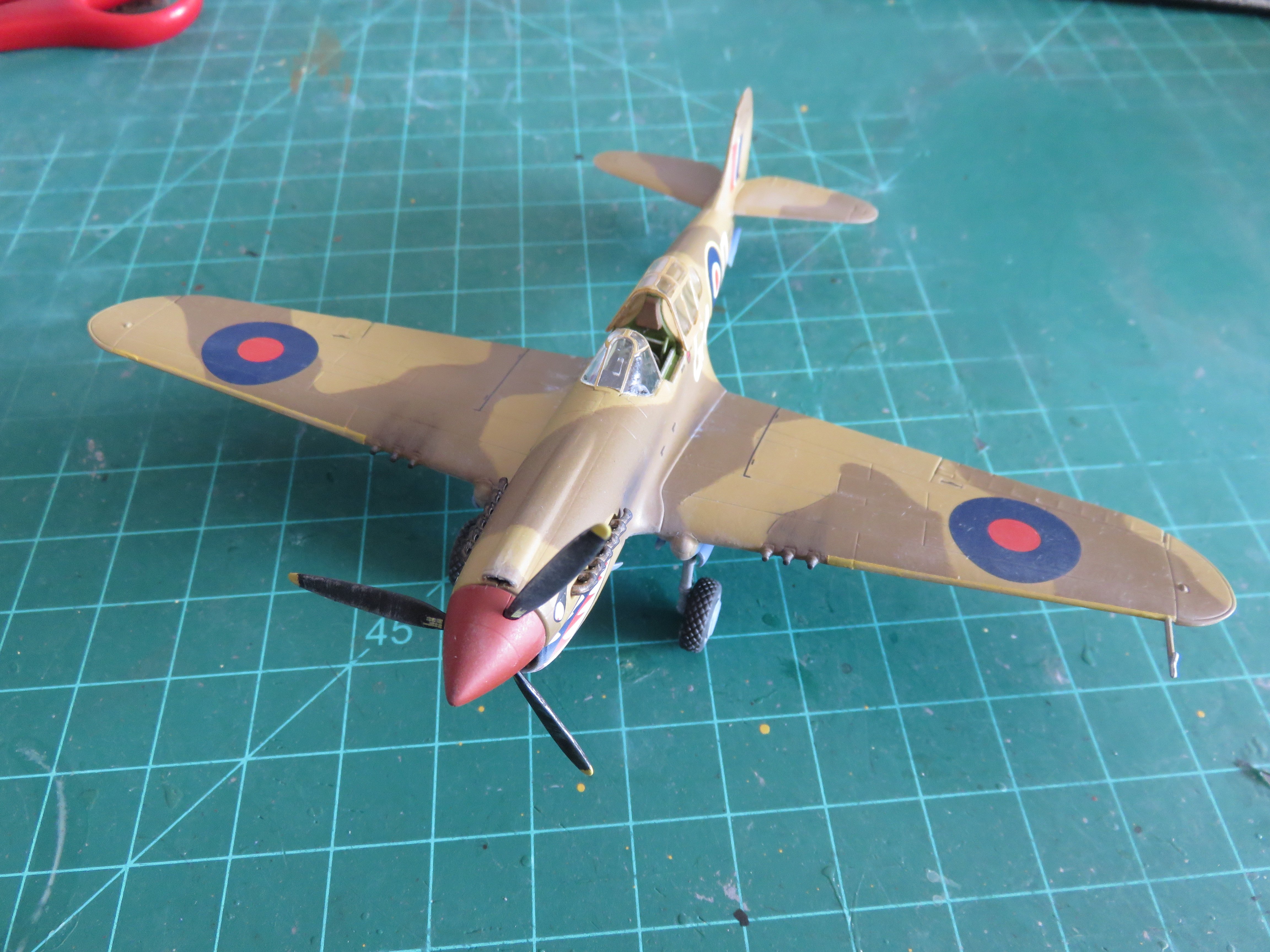
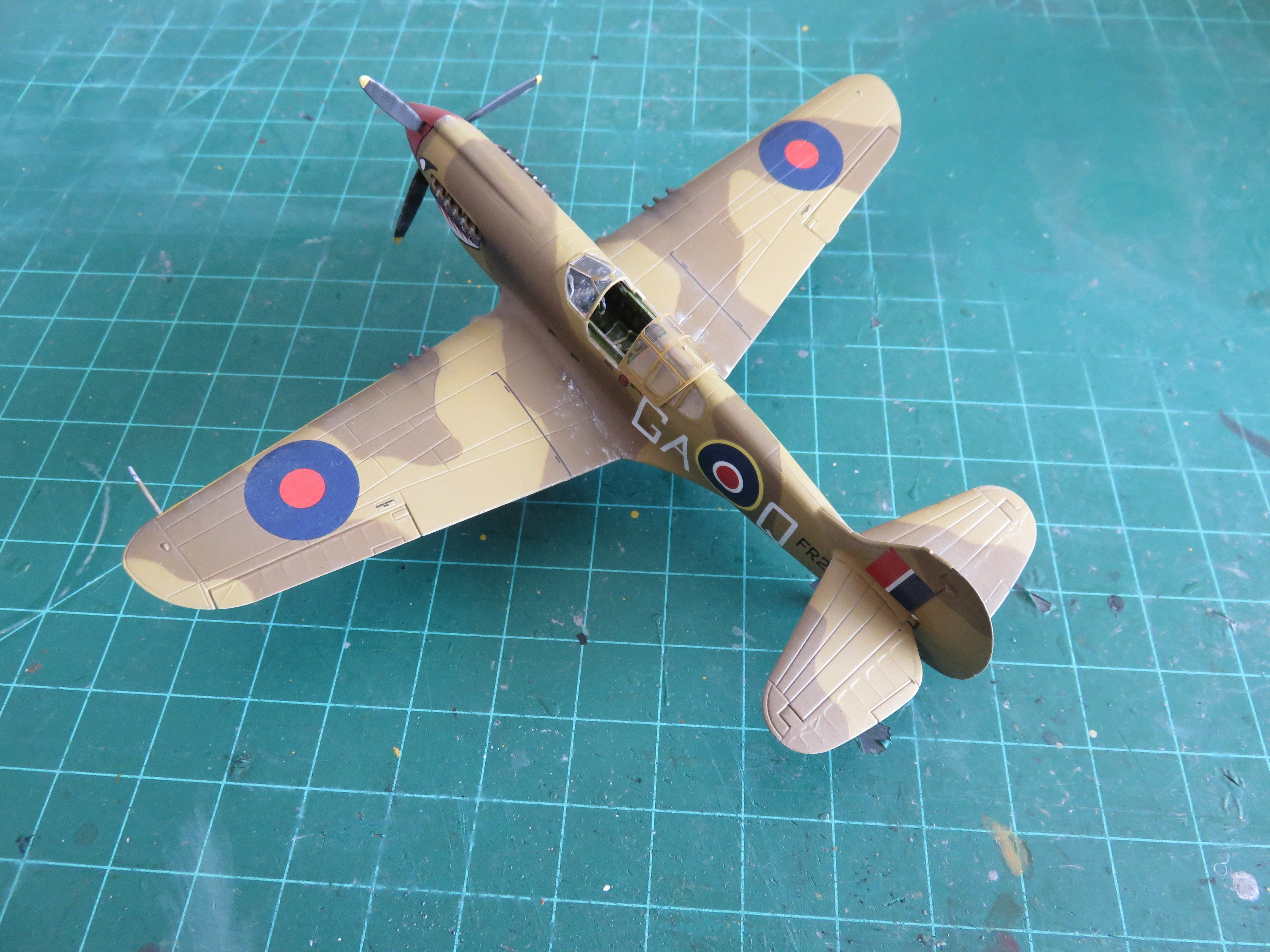
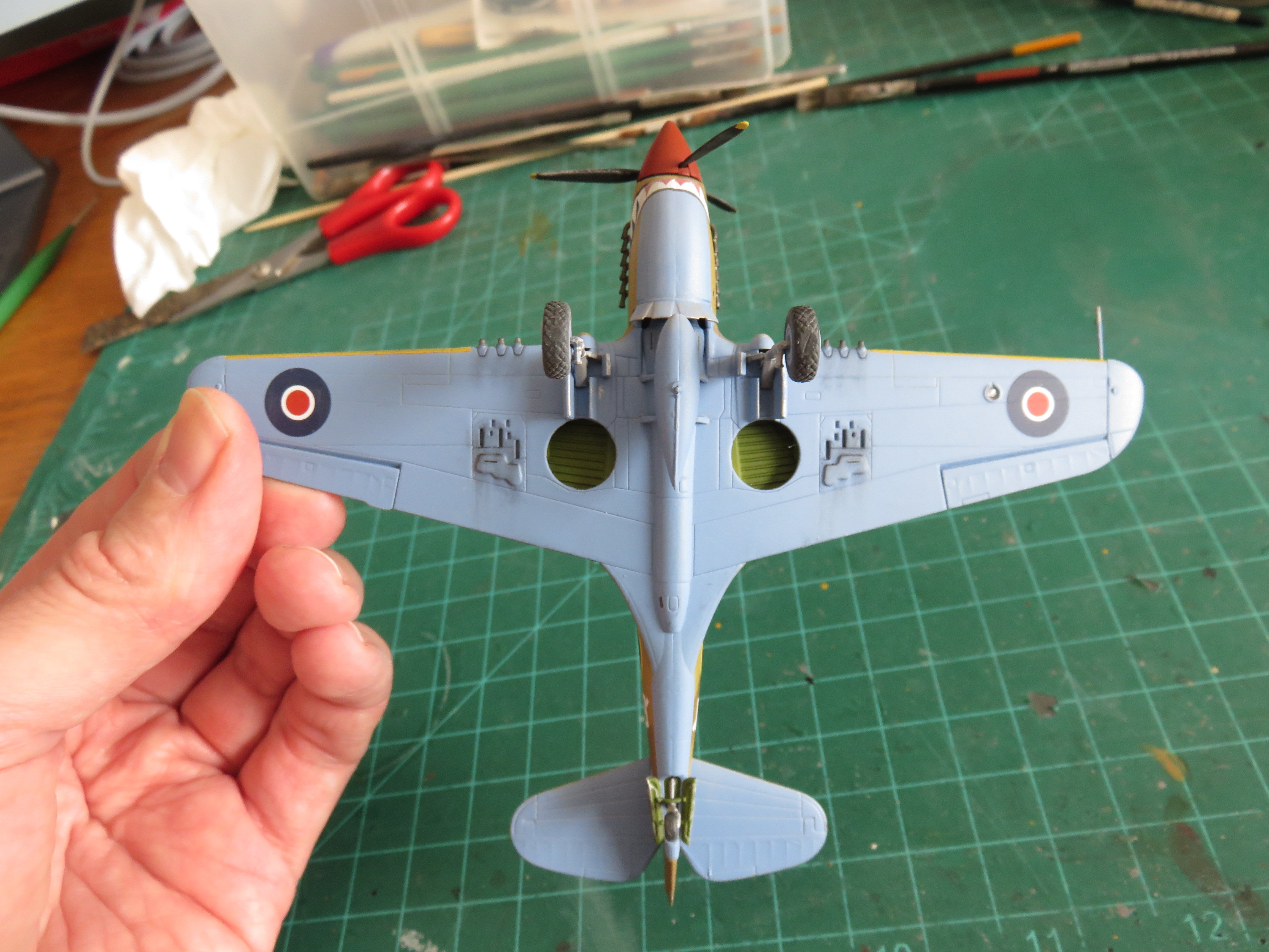
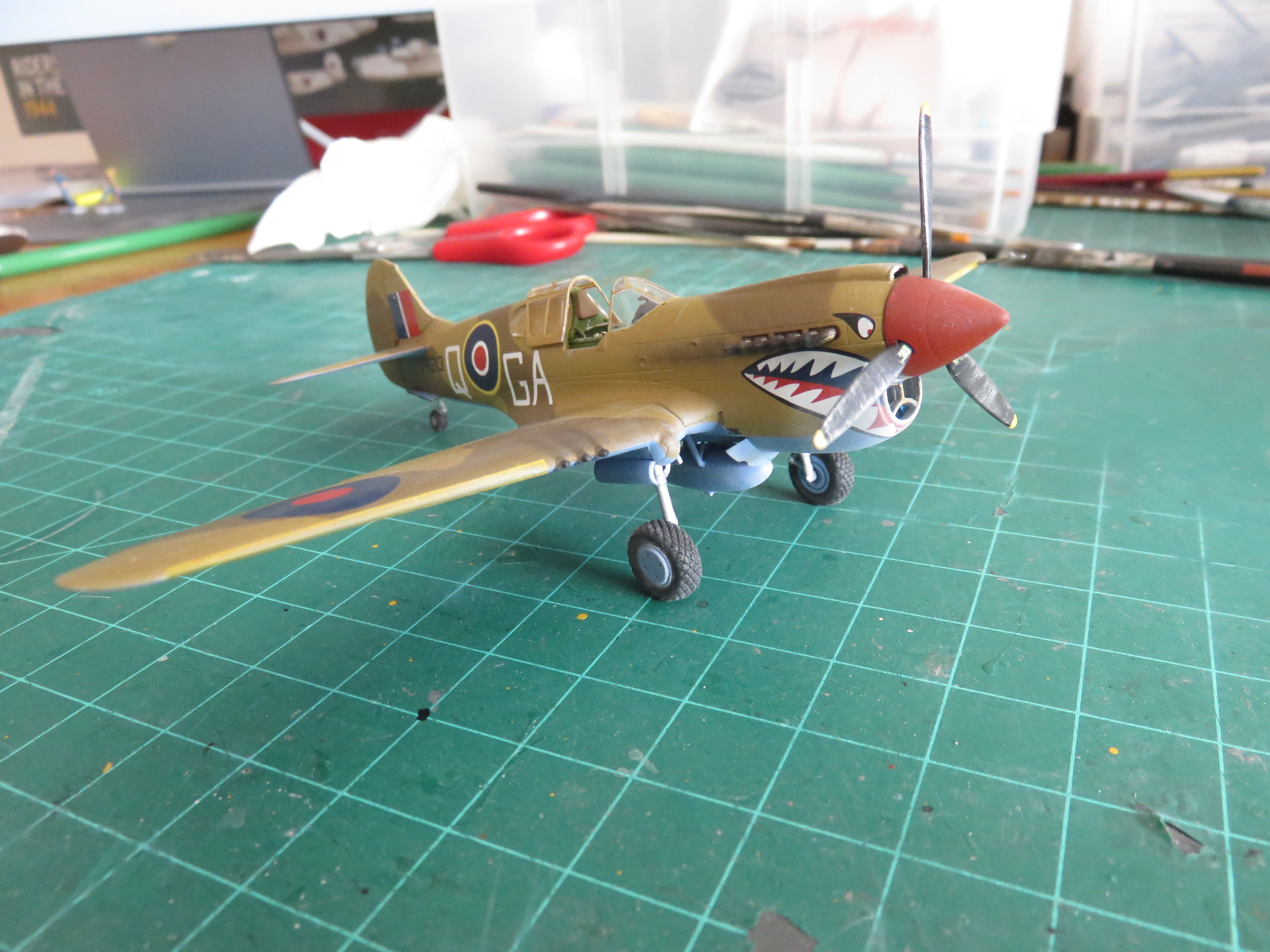
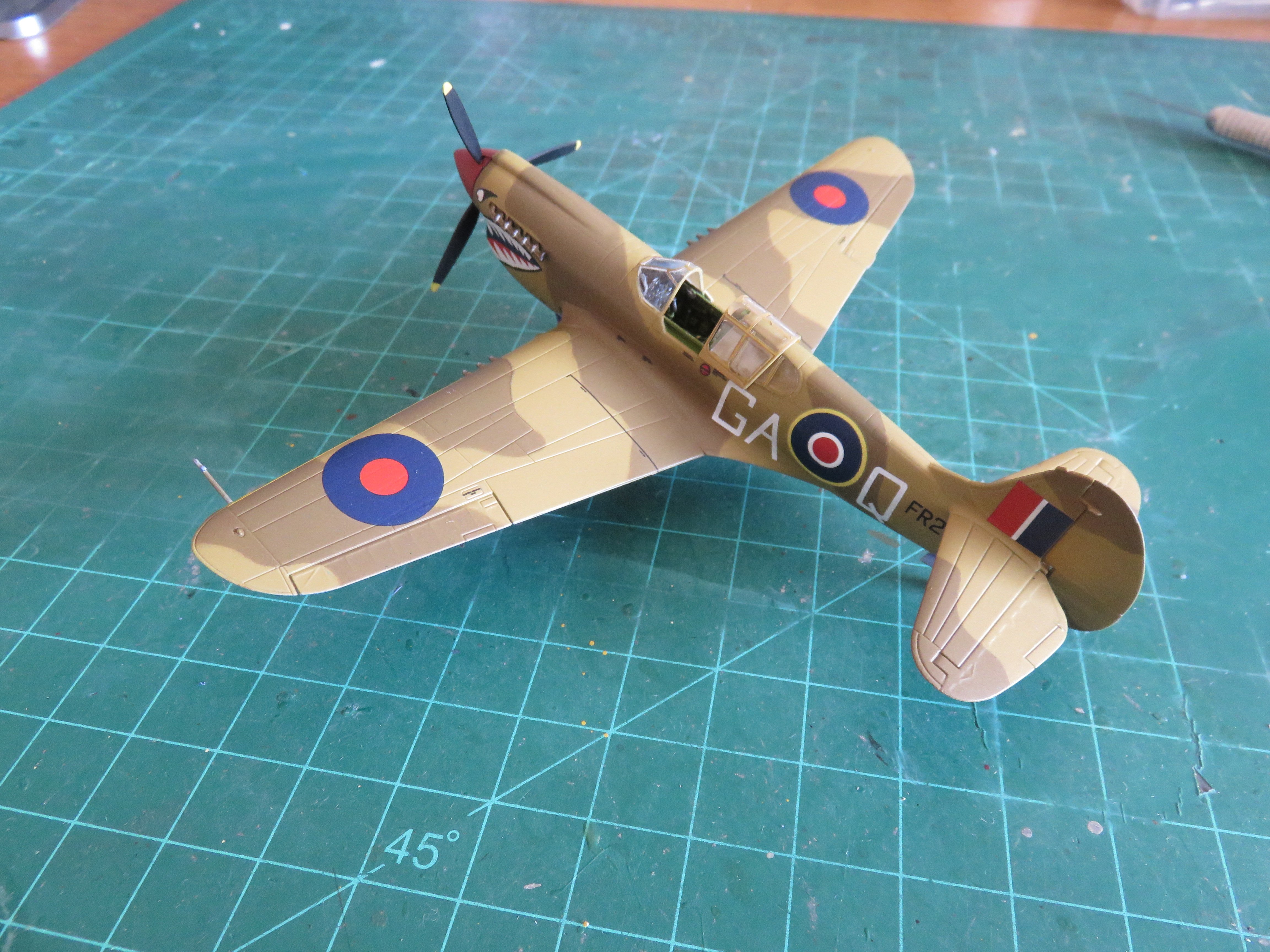
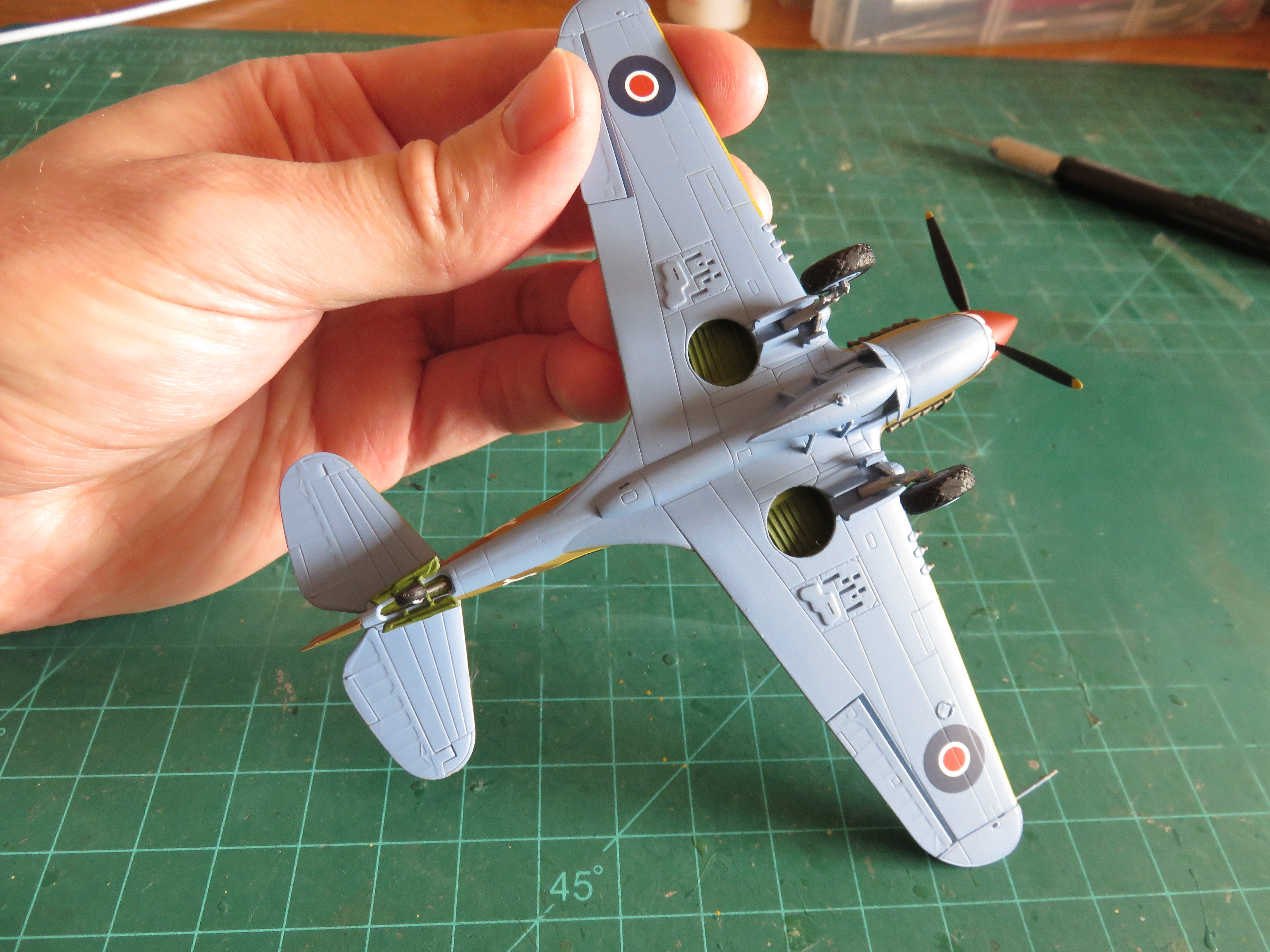
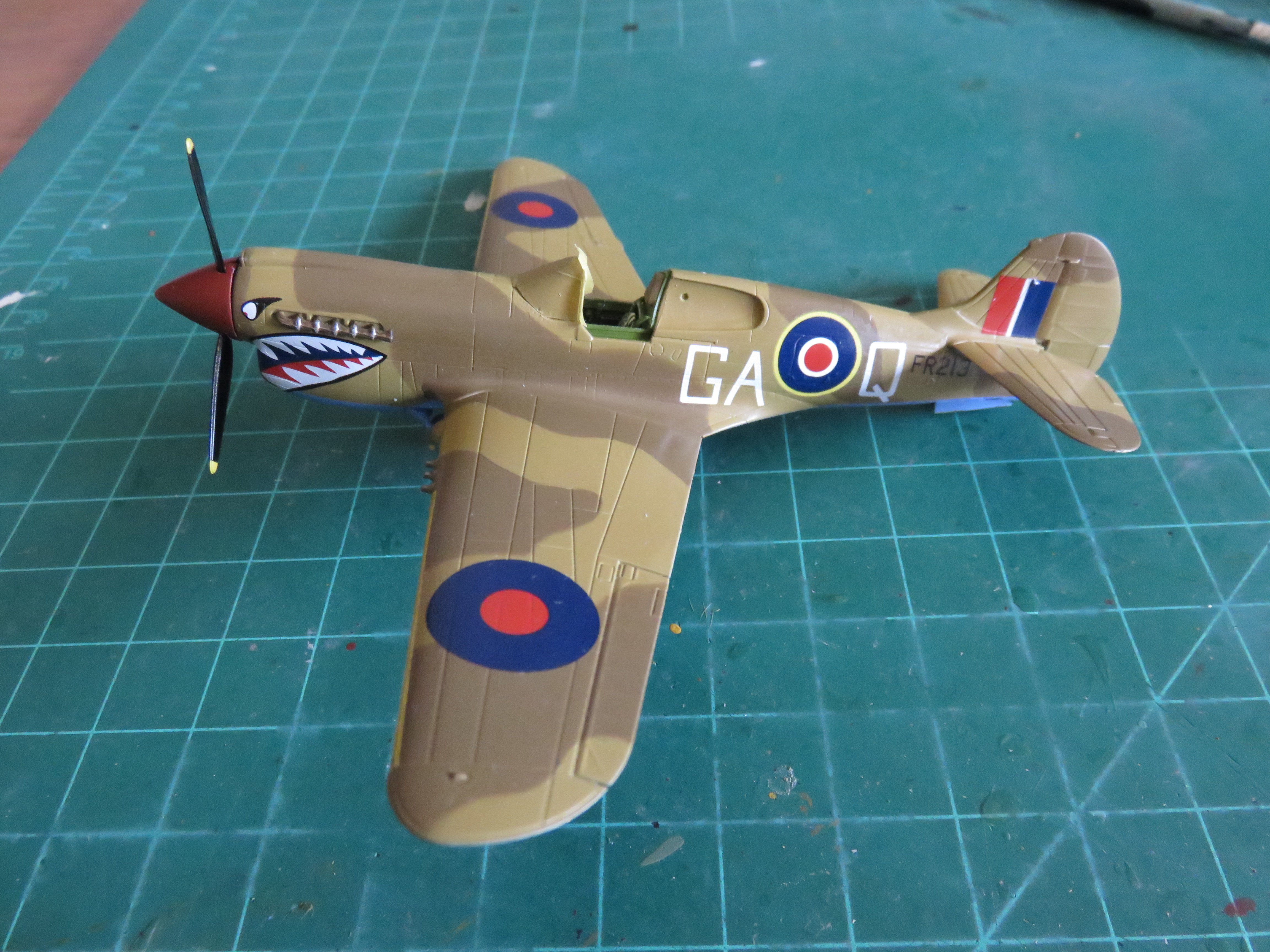
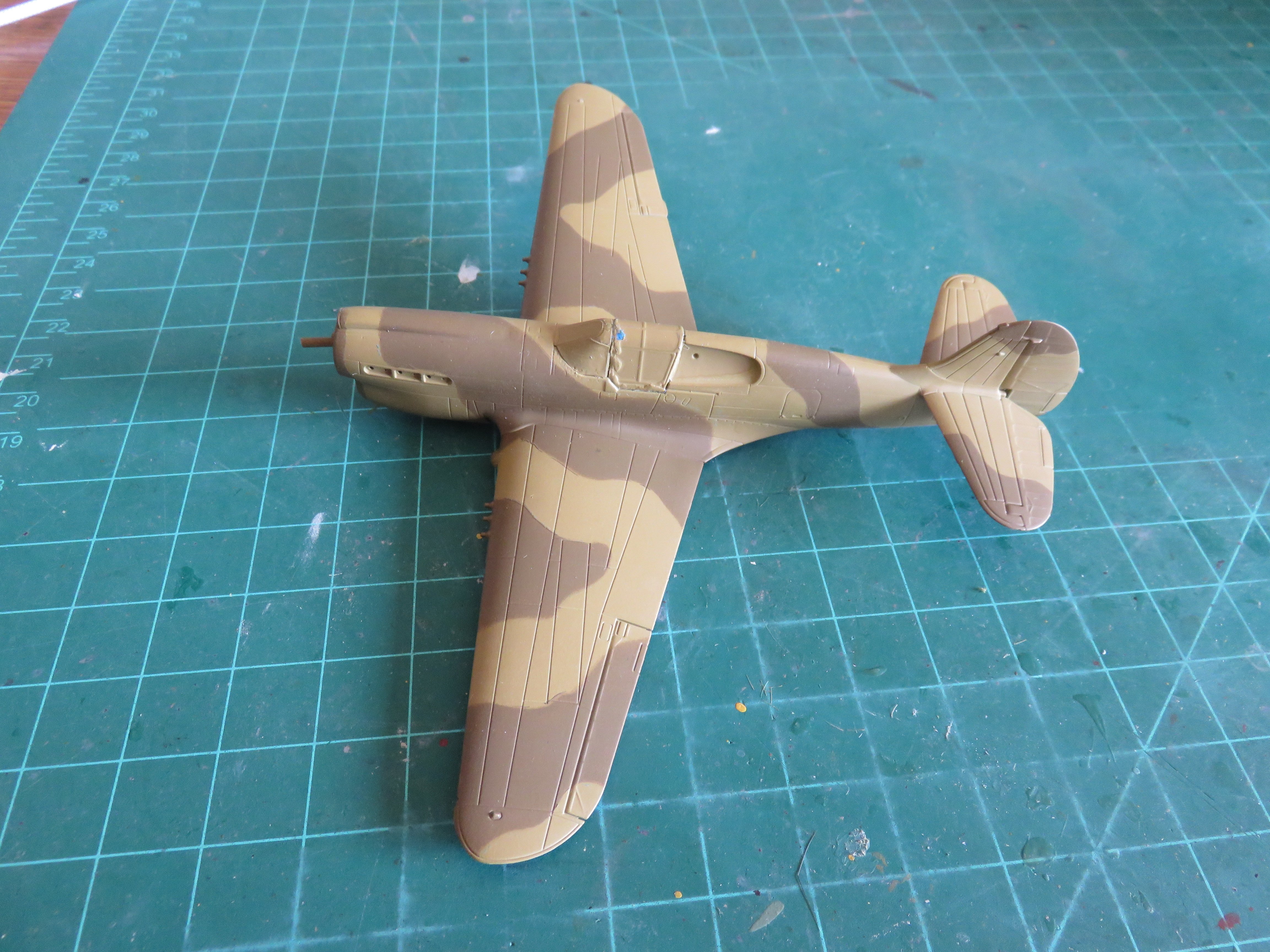
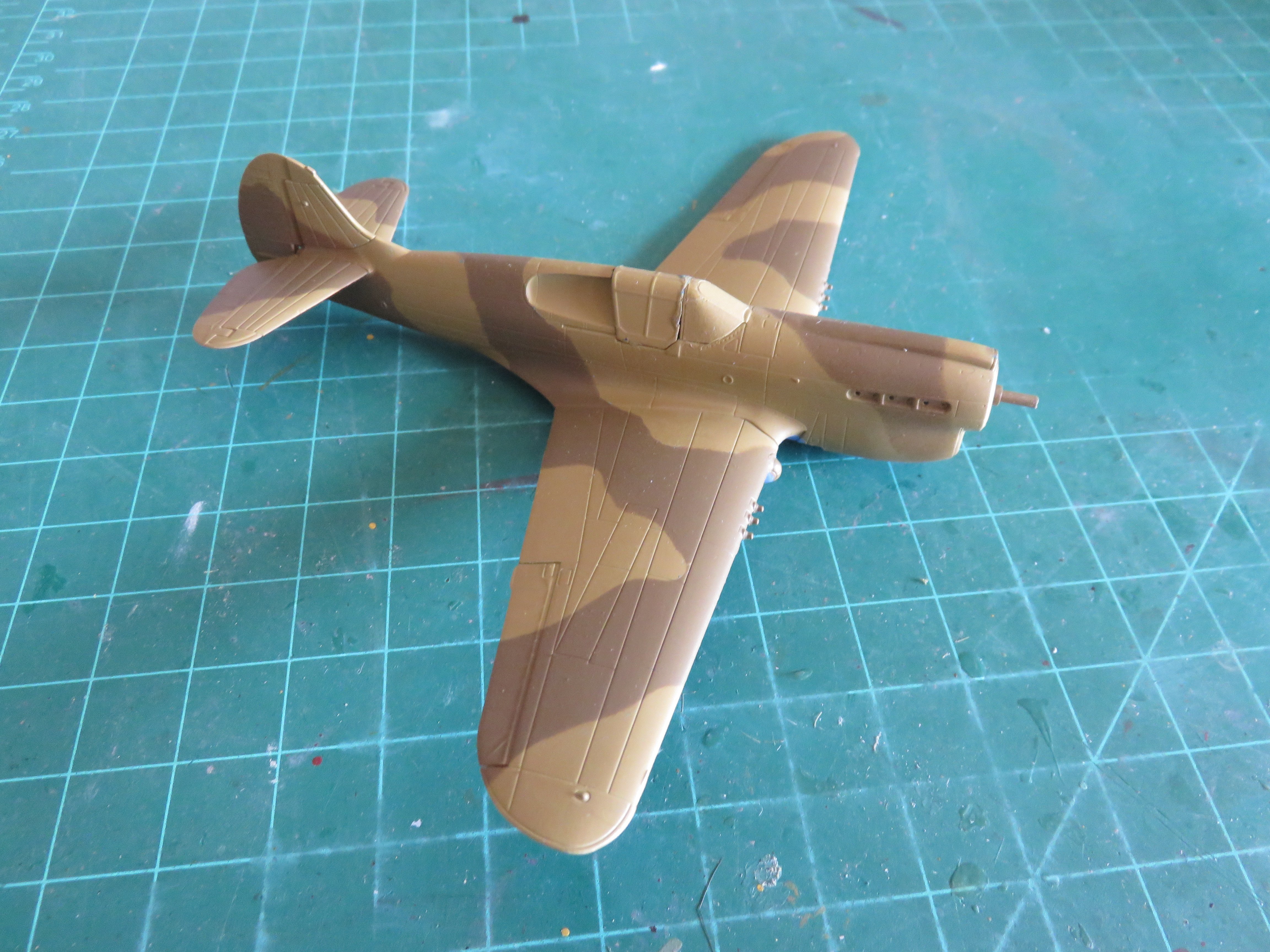
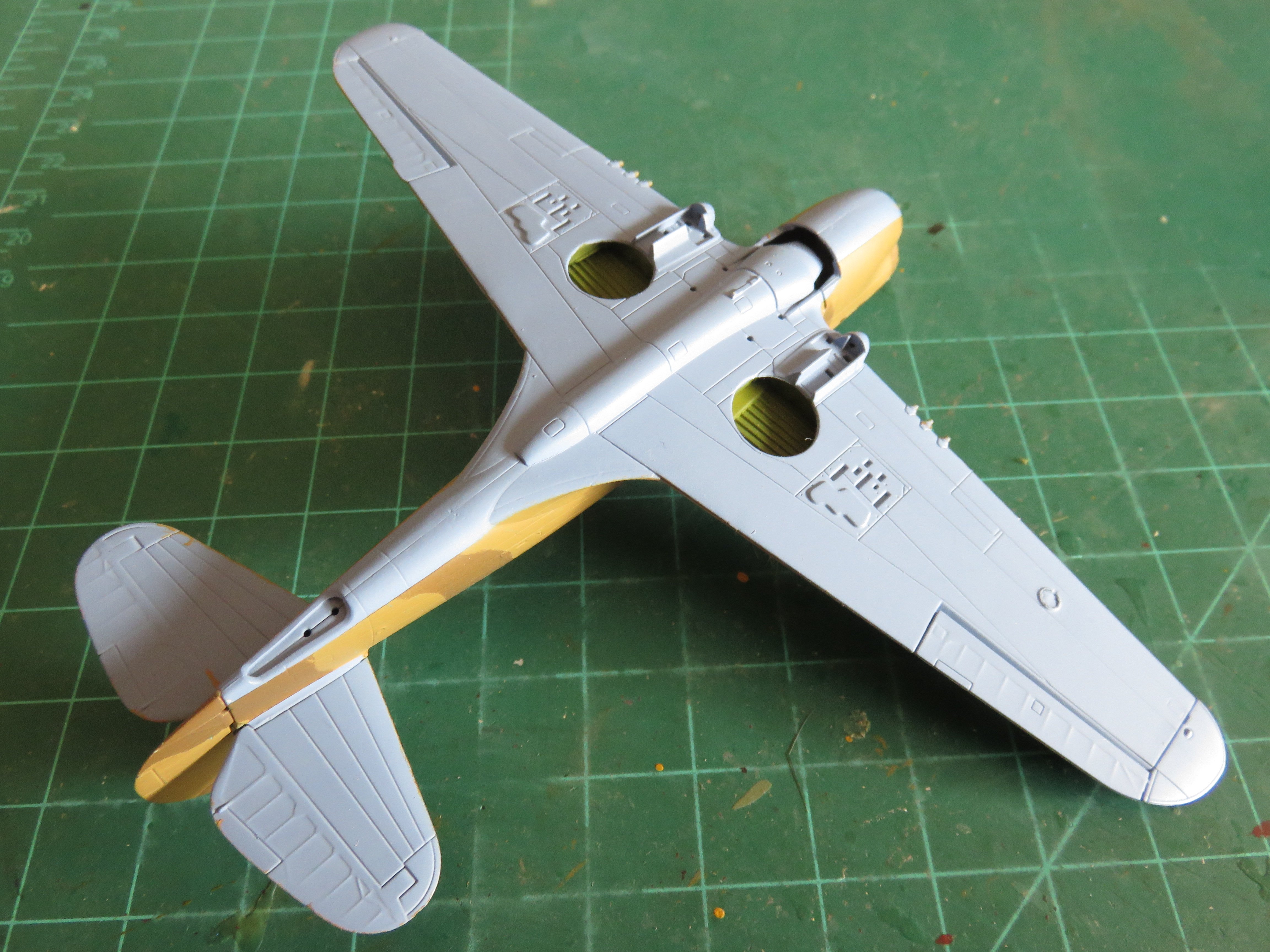
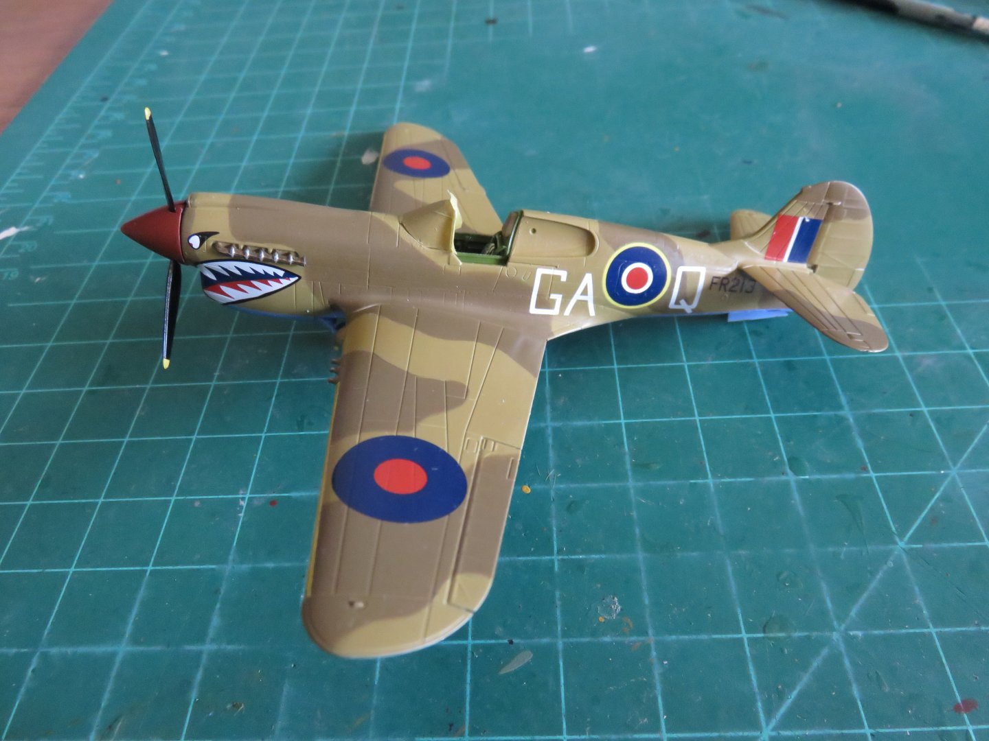
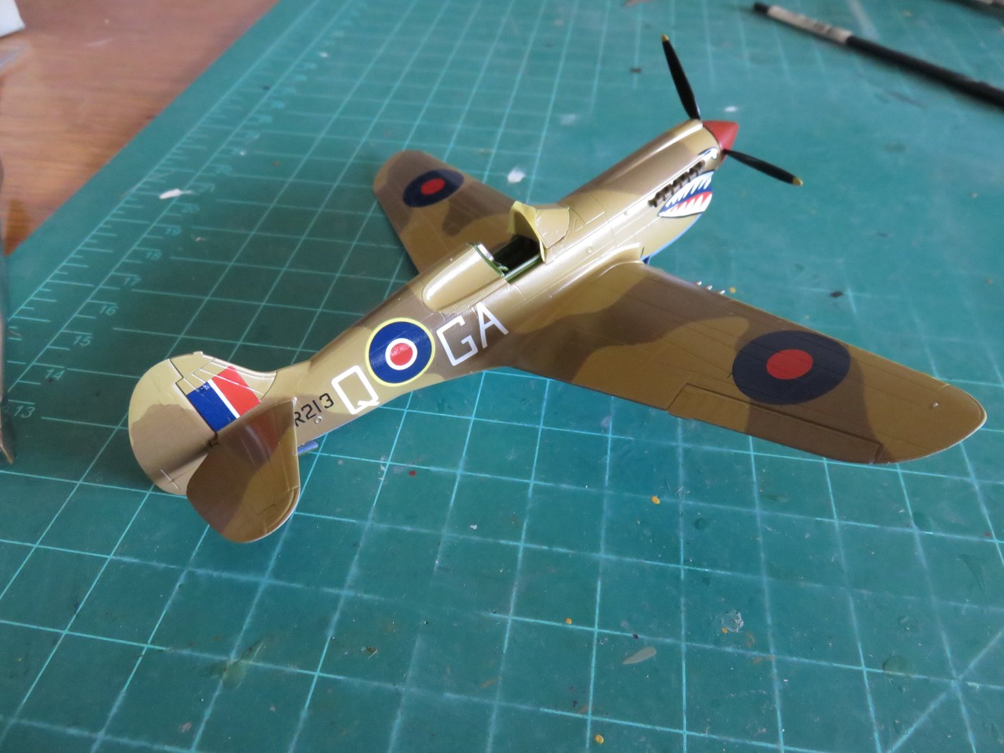
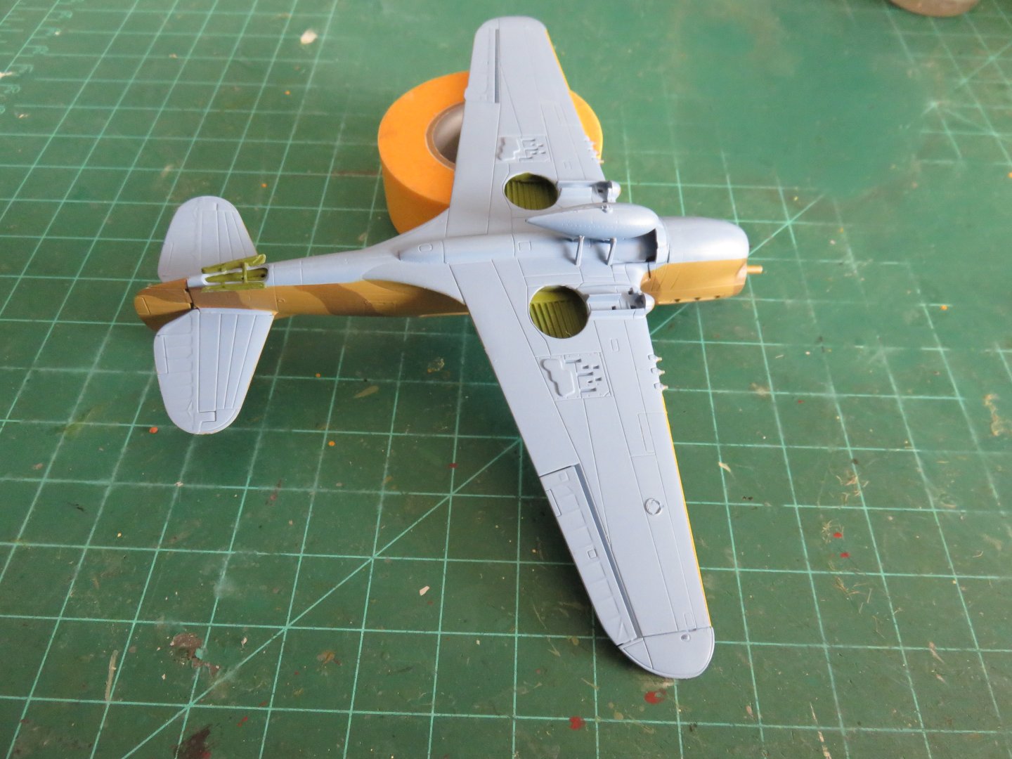
Thanks to everyone, as always, for the kind words and likes! A small update to share with you all! Major painting is now finished. A nice milestone to have achieved in any build! The final element involved the application of the yellow leading edge ID stripes, fighter command stripes, or whatever they're properly called! A little bit hard to see in this photograph, I'll admit, but they're there! They show up a bit better in this photo: Digging for photos online produced some mixed results in trying to determine if the yellow stripes were in use or not. It seems to have been on a squadron by squadron basis. Most importantly, for 112 Squadron, they were applied. As you can see, I have also pulled off the "masking" canopy so I can touch up any of the small missed areas or any bleed before I add a clear gloss coat in preparation for the lettering. The underside of the plane was also not ignored: The tail landing gear doors have been added and the interior sides painted green. I've also added a drop tank. It took me a long time to figure out if I should add one or not. From what I've been able to dig up online, no photo of a 112 squadron P-40 exists with a drop tank attached. However, one many pictures there are brackets. Not sure if those were for a bomb or a fuel tank. Some great colour photos can be found here. Ultimately my decision came down to necessity and a bit of modeller's license. If you take a quick scroll up to my last build update, you can see four holes on the belly of the aircraft, inboard from the landing gear bays. in order to avoid using a bomb or belly tank, I would have had to fill those holes. I hadn't fully made up my mind about things when I started painting, and I didn't want to delay the build any further. Ultimately, seeing prototype pictures of the empty brackets suggested that I was free to do what I wanted, and I think the belly tank does look pretty good on a P-40 anyway. Besides, I haven't yet made an airplane model with an exterior fuel tank, so it was about time! That's about it for now. Hopefully the next update will see the lettering applied! Thanks again for the comments and likes! Andy

- 53 replies
-
- 13
-
-
Yours looks great too! Your reddish dark earth might be more correct for a Curtiss built plane as they used DuPont paint, rather than UK manufactured, so some of the colours had a slight variation from the “British Standard” colours. Andy
-
Thanks Alan! Yes, they are the Vallejo Model Air series. I’m not certain, but I would think they are of the same base formulation as the majority of their full acrylic colour ranges. I have experience spraying humbrol, polyscale, floquil and now Vallejo paints with my airbrush. And I would say that the Vallejo is just as nice as Floquil lacquer, and way better than polyscale. I think the Vallejo airbrush flow improver is the key to happy spraying. I’ve noticed the drying time is extended by a significant amount using only a drop in my airbrush paint cup. It may work well with other brands of water miscible acrylics, I’ll have to do some testing. I admit I don’t have much experience with other paint brands, but now that I’m properly set up, I will have to begin some experimenting! Andy
-
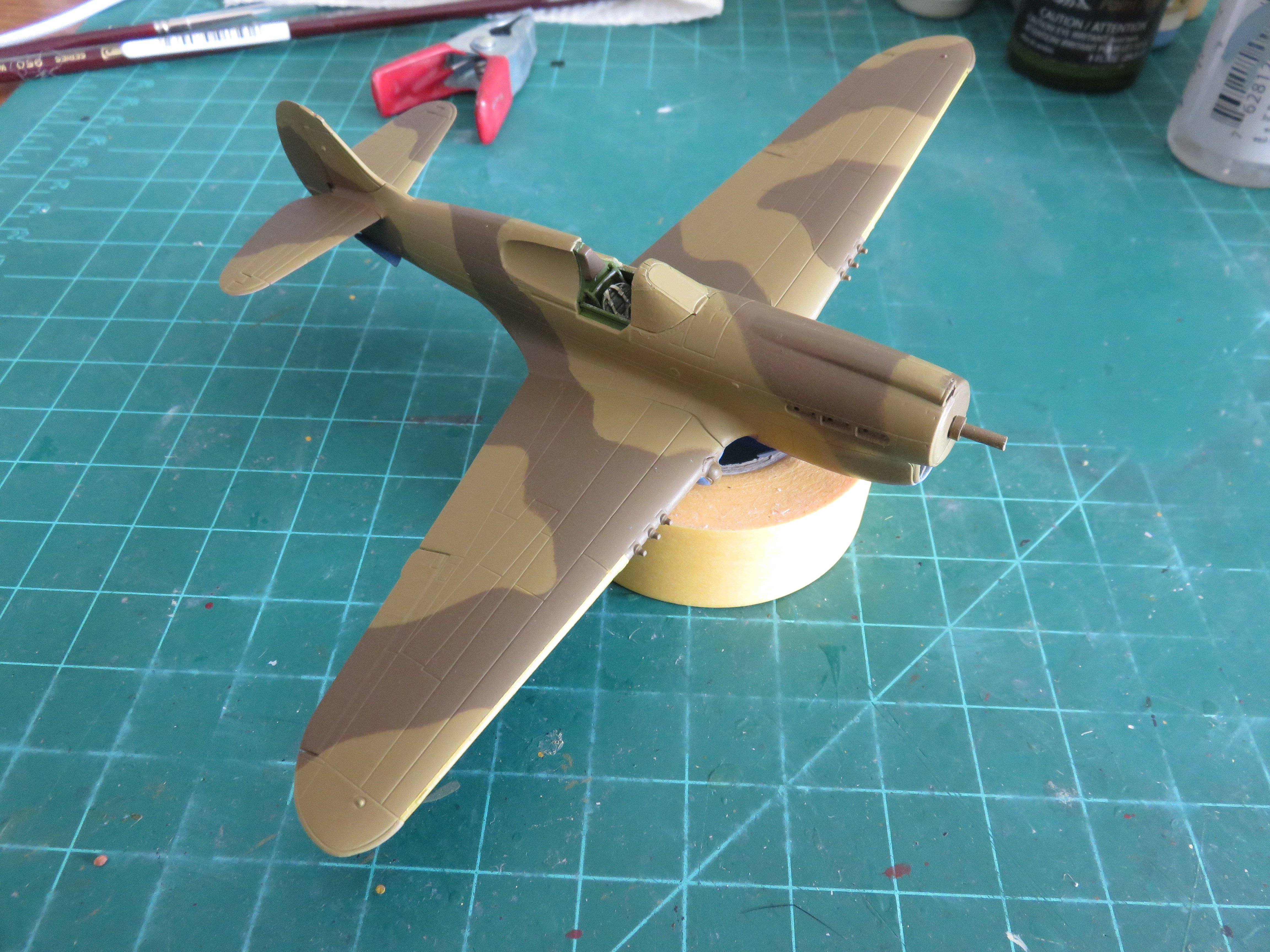
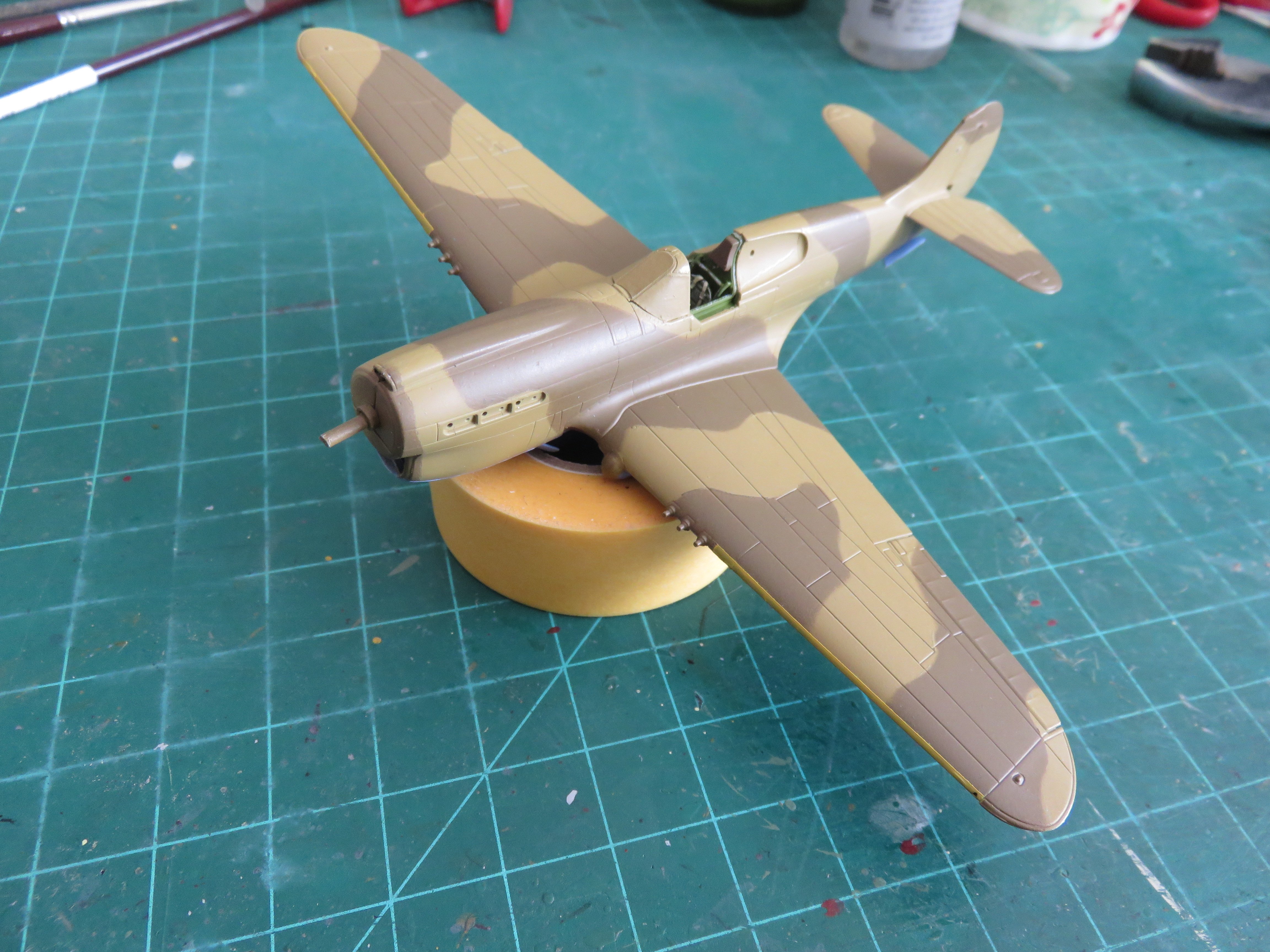
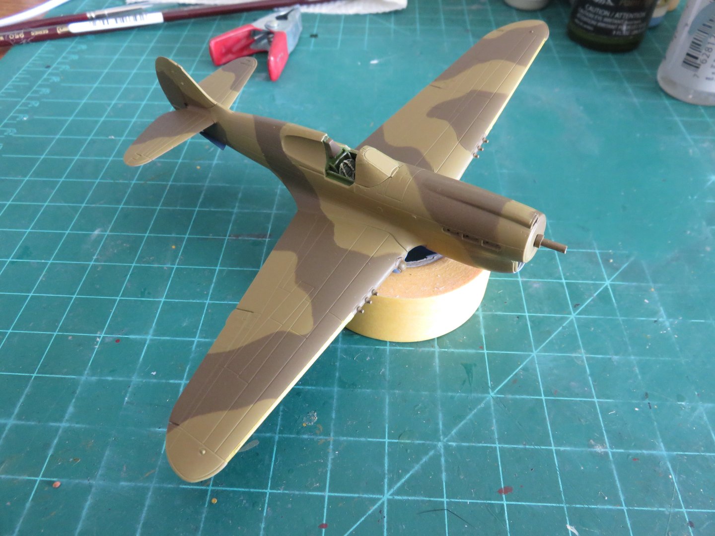
Has it been that long?? I had hoped to be able to get more time at the workbench over the last six weeks or so, but life has a habit of getting in the way. So do warm sunny days..... After my last update, I did get the cockpit buttoned up and a coat of primer applied. The main canopy hood is just held in place with some poster putty for now. It is serving simply as a paint mask. I will display the model with the canopy open, and SH has a separate part for that. In the above photo, you can just make out that I have also applied the Azure blue underside colour. I have opted to use Vallejo acrylics for this build, making use of the nice spray booth and compressor that I got back in June. The last couple of weeks I managed to get the upper colours applied as well: A few touchups here and there, as usual, but I'm fairly happy with how things are looking at this point. The underside contrasts nicely with the upper surface colours. Following the touch ups, I will have to mask and paint the yellow "fighter command" stripes on the wing leading edges outboard of the guns. That should be fun..... Overall I am enjoying using the Vallejo paints. Using their thinner and a drop of flow improver, I haven't had any nozzle clog issues, and I'm able to spray at a relatively low pressure, with no spattering. All problems I've encountered in the past with other acrylic paints (ahem....Polyscale...cough cough). I hope to be able to provide more frequent updates in the near future. Thanks to everyone who's still following along and all your kind comments and likes! Andy


- 53 replies
-
- 16
-
-
-
It strikes me as a bit odd, as for years model railroad sound decoders have been able to play the full range of engine sounds from startup to idle to full throttle (and everything in between), sequenced to whatever the controller throttle is set at. “Engine startup” when electrical power is first applied (or the locomotive’s digital address is selected), endless idle sounds until a movement order is sent, then the appropriate increase in engine rpm to a new setting, and so on. For the price of the kit, and other qualities not withstanding, I think they could do better on the sound than having just a continuous startup sound loop. Andy
-
If you look up “Lanz Bulldog”, the Wikipedia article gives a good insight into how that type of engine works. Plus there’s a lot of interesting YouTube videos of people starting and running them too. Very distinctive sounding engine. Andy
-
Nicely done Chris! Now you need your own desert P-40 to go with it! Andy
-
Doing some digging around, it would appear the chemical in question used in the Tamiya spray paints is 2-Butoxyethanol CAS no. 111-76-2 I believe this is used to forestall the drying process in acrylic paints. Vallejo used to have it in their airbrush thinner and flow improver. If I’m not mistaken Mr Surfacer is a lacquer paint and shouldn’t have 2-Butoxyethanol in it. Andy
-
Yesterday I was shopping online at a Canadian hobby store and noticed an announcement regarding Tamiya spray cans. To summarize: Effective September 24th the importation of all Tamiya spray cans has been banned. This includes all paints in the TS, PS and AS ranges and all forms of Tamiya spray primer, but does not concern any non-aerosol products. Retailers are permitted to sell their remaining stock, but all imports have been halted. Any stock held by distributors has had to be destroyed. There seems to be a lot of online hysteria regarding this ban, but it is NOT a political issue. There is a chemical component in Tamiya spray cans that has been banned in Canada since 2010, due to environmental and/or health concerns. This is likely a case of the government regulators finally getting around to evaluating Tamiya’s products. I would also strongly caution anyone trying to import Tamiya paint via a US or other foreign retailer. If Canada customs decides to inspect your parcel there’s a good chance the paint will be removed and destroyed, and likely you will have a struggle to get any form of refund. Andy
-
The irony is, I’m used to working in 1/87 scale with my model trains, so 1/72 is a bit of an upgrade in that respect! 😅
- 53 replies
-
- 10
-
-

-
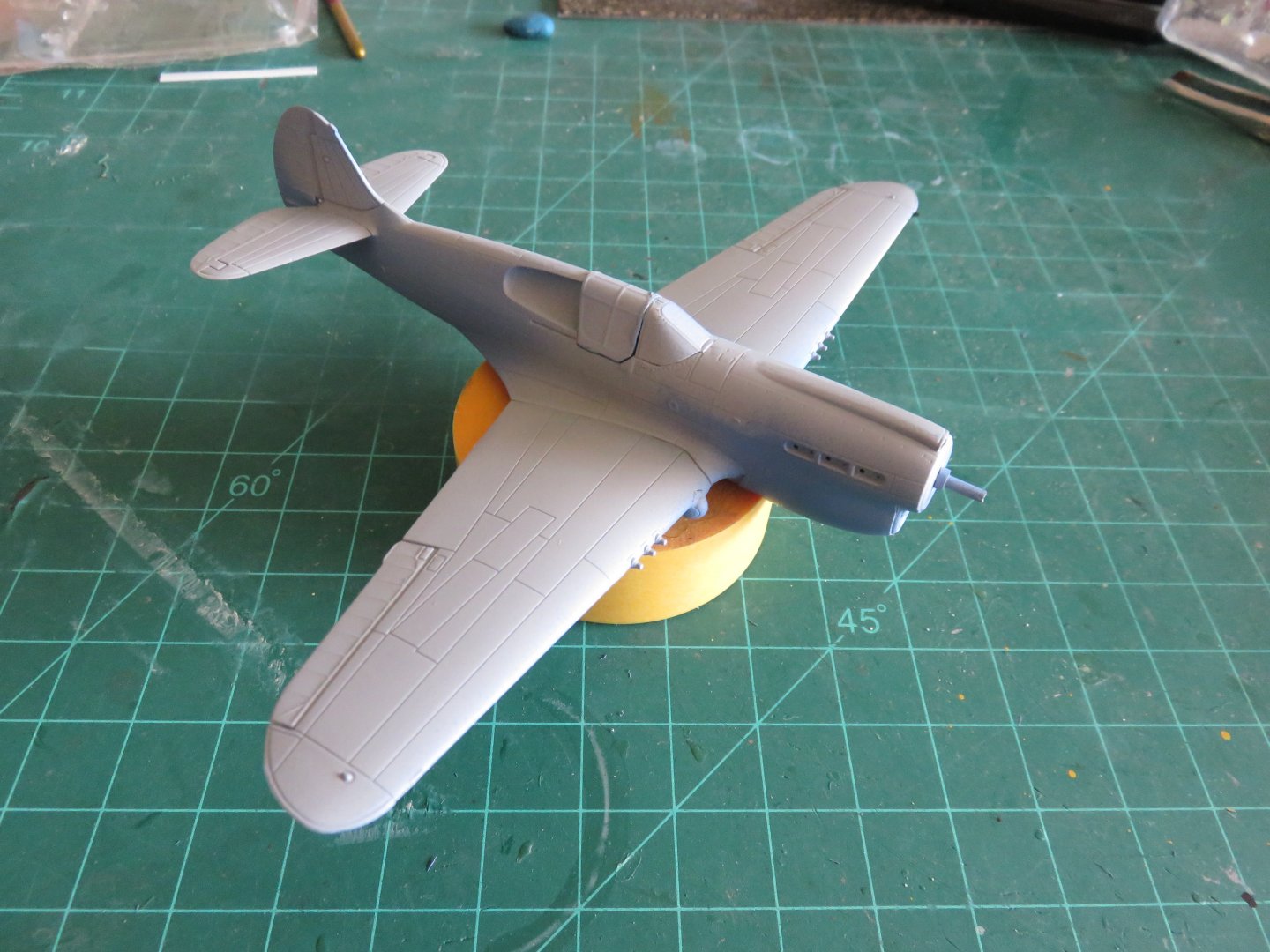
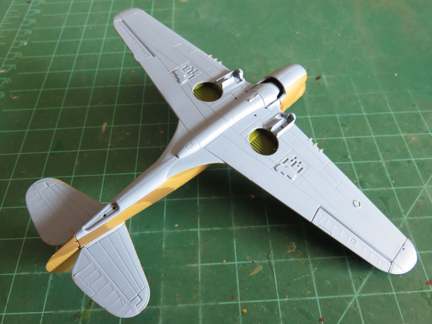
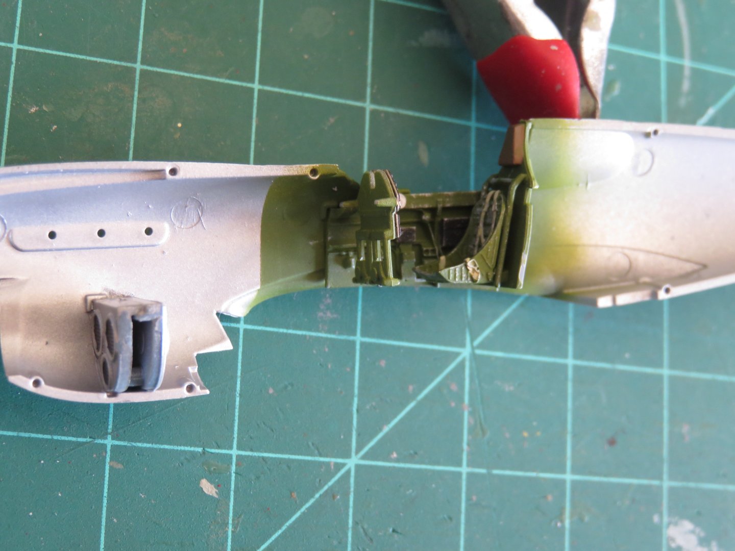
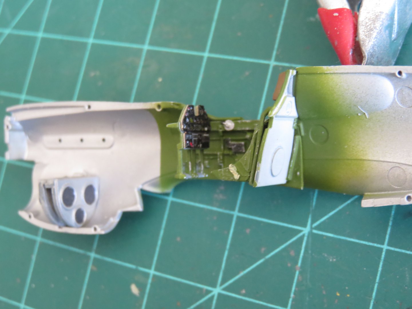
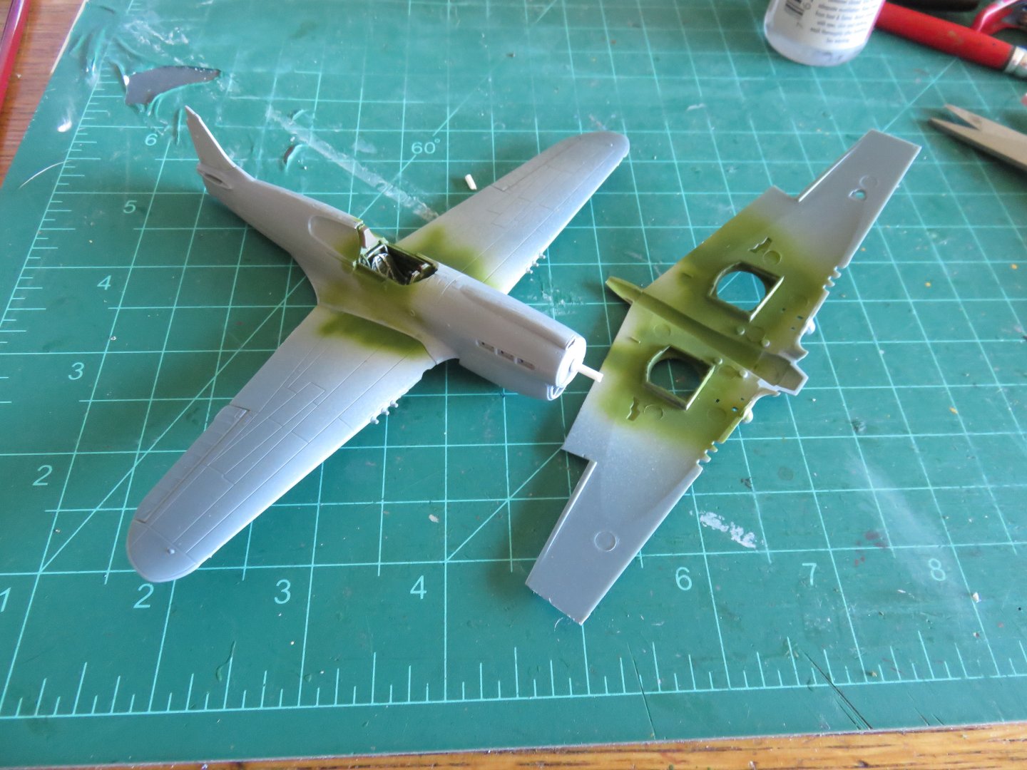
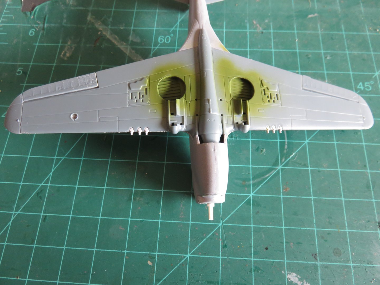
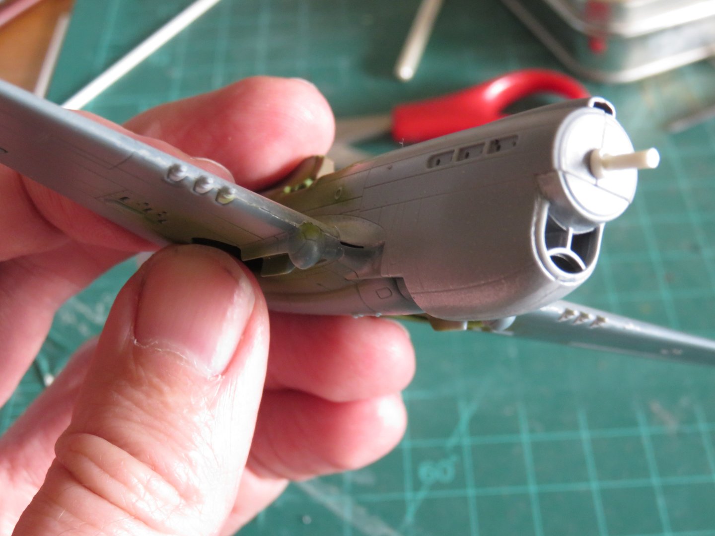
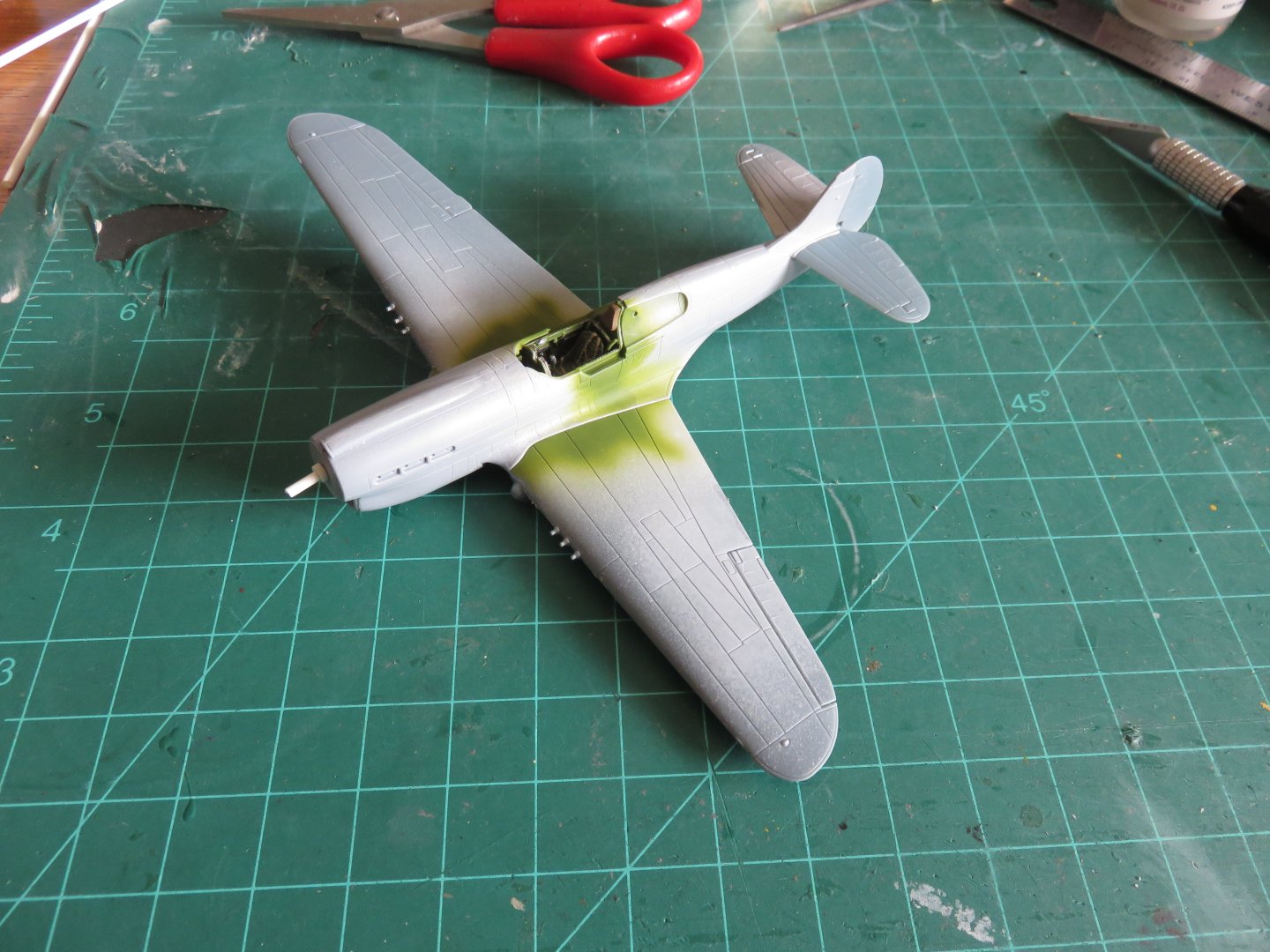
Good afternoon everyone (at least, it's afternoon where I am), thanks for all the likes and comment! A bit of progress to report! The cockpit and interior components went together well, and fitted into their proper locations without any issues. Big difference from my Skua build, no guessing, everything fits positively. After a bit of dry brushing with some silver to simulate worn paint, I added the rear bulkhead along with the pilot's seat as well as the instrument panel (with the rudder pedals). This was then followed by the radiator/oil cooler core in the chin. You can see the little alignment tab for the radiator core. The bulkhead slid into a slot on the cockpit side. As there is now a fair degree of resin parts in the cockpit, CA glue was needed to secure everything. I dry fit the other fuselage half to ensure everything dried in the correct position. A quick last look at the instrument panel before everything is buttoned up. I then took my first two deviations from the kit instructions. After assembling the fuselage (which fit wonderfully, and only needs a bit of fine sanding along the seams), the next step calls for the installation of the wing. The instructions would have you assemble the wing halves before adding them to the airplane. I attempted this in a dry-fit and found the things weren't going to work that way. I found it was easier to add the top of the wing to the fuselage first, then add the lower half of the wing after the upper has dried. Another testament to the improvements being made at SH, there are no gaps in the wing roots to speak of. The joint is obvious right not because of the overspray from earlier, but they should look better once there's a proper coat of paint on. Another deviation was how the propellor will eventually mount. SH seems to have a thing against spinning props for some reason. I, for one, prefer the spin-y bits to spin. a bit of 1/16" styrene rod, along with some 1/8" tubing (to act as a backing plate) and I should be able to mount the propellor to that to enable it to spin freely. The lower half of the wing was then added (don't forget to add the little clear part for the landing light!) It slotted in nicely and only a little tape was needed to secure it while the glue dried. There is a small gap at the leading edge of the wing (this is the first one I've found!): A little bit of filler and some sanding should have that nicely tidied up (there's another small gap on the other side in the same location). The intake for the chin fairing was added just before adding the wings. The last bit of work done to date was to add the rudder and horizontal stabilizers. These all fit nicely, in keeping with the kit quality experienced so far. There's not too much left to add before paint starts flying. Hopefully for my next update, there will be some colour! Andy
- 53 replies
-
- 13
-
-
Rather than type up a long winded response, I'll let Greg handle it (he explains it better anyway): https://www.youtube.com/watch?v=KGFsAOUdX7A Andy
-
An interesting explanation of the aerodynamic properties of the P-51: (Note: the presenter’s information is all sourced from primary source documents and test reports) Andy
-
I feel compelled to jump in, if you don’t mind, with a small factual (fun?) tidbit. The prototype photo you posted is in fact a P-51H model, not a P-51D. Aside from other design changes, it used an entirely different NACA wing profile than the “D” model, and can be most easily recognized by the straight leading edge. Andy
-
Greetings everyone! The autumn weather is now upon us, and it seems a little more appropriate to spend some time at the work bench building small things again! Over the last weeks I have begun picking away at my P-40 project. It took a little bit to get the momentum up after a summer off, but I think things are finally picking up a head of steam! First up, I did a little bit of work on the sprues fitting some of the aftermarket resin. The CMK cockpit sidewalls are a drop in fit that directly replace the kit parts. \ The detail level is much improved over the originals: Not that much will be seen anyway! After working through the first couple of steps in the instructions, most of the interior is now completed and painted. I have put my new spray booth and air compressor to work, and I am so happy to be able to use my airbrush again! Rather than make some custom mix, I simply sprayed Humbrol interior green #226. Seems to be reasonably close to some of the colour photos I've found online of P-40 cockpits. Some of the details were picked out in an appropriate colour. The next sept will be to adda little light weathering and some dry brushing with some silver paint to simulate a little wear and tear, but apparently I will have to do a little dusting first! The remainder of the interior components consist of the radiator/oil cooler assembly. The instructions say to simply paint it an aluminium colour, but I added a little gunmetal in the grills for visual interest. The instrument panel was a Yahu models replacement, I added this after sanding off the moulded details. The final bit is the armour plate and cockpit seat. The seat was another CMK resin product that came complete with moulded on seatbelts. A little weathering on these parts (and some more dusting) and they will be added to the fuselage. Yeesh, this macro photography business is going to drive me nuts! The remainder to the cockpit floor is moulded on to the top of the wing section. Again a little chipping and weathering (and dusting) is in order. Jumping ahead a little bit I've also installed and painted the interior of the wheel wells. Unlike my Blackburn Skua build, the wheel well frames don't require any sanding to allow both halves of the wing to fit together. The Skua wheel wells required considerable plastic removal before the wing halves could even get near each other. I must say, that so far I am thoroughly enjoying this kit! As one of Special Hobby's newer offerings, the fit of the parts is much more precise than in their earlier kits. There are locating pins and tabs to make sure parts end up in the right place, and a cursory dry fit of the fuselage and wings seems to suggest that only minor filling and sanding will be required (a precision on the level of some of the better Airfix kits!). Definitely a kit worth building! Andy


- 53 replies
-
- 12
-