realworkingsailor
-
Posts
3,274 -
Joined
-
Last visited
Content Type
Profiles
Forums
Gallery
Events
Everything posted by realworkingsailor
-
 I think it was the early to mid 00’s when Noch brought its static grass and electric applicator to the North American model train market. The model scenery “industry” had come a long way from the days of dyed sawdust! Andy
 -
P-51D Mustang by CDW - FINISHED - Dragon - 1:32 Scale
realworkingsailor replied to CDW's topic in Non-ship/categorised builds
If you haven’t seen it, this might interest you: Andy -
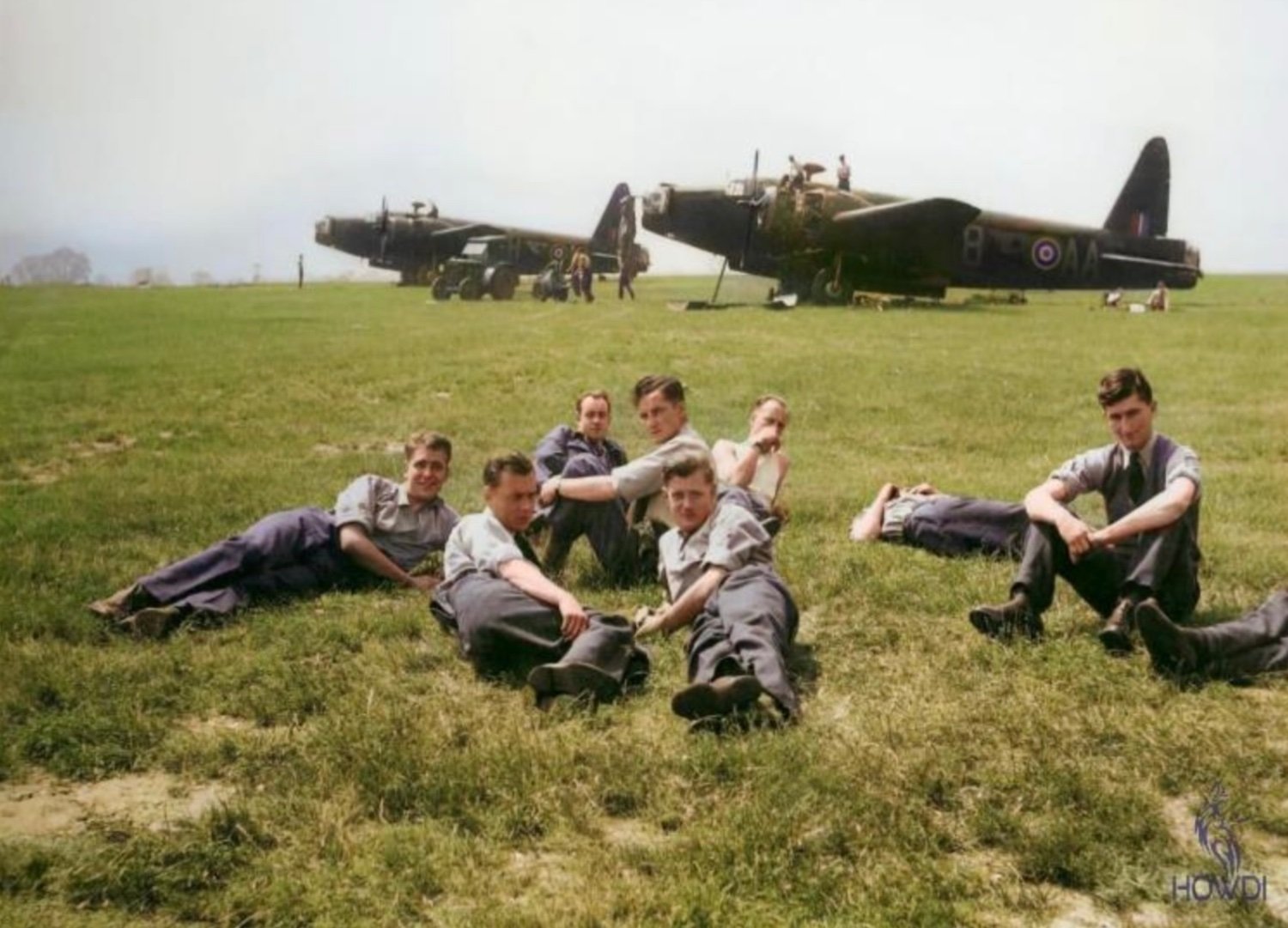
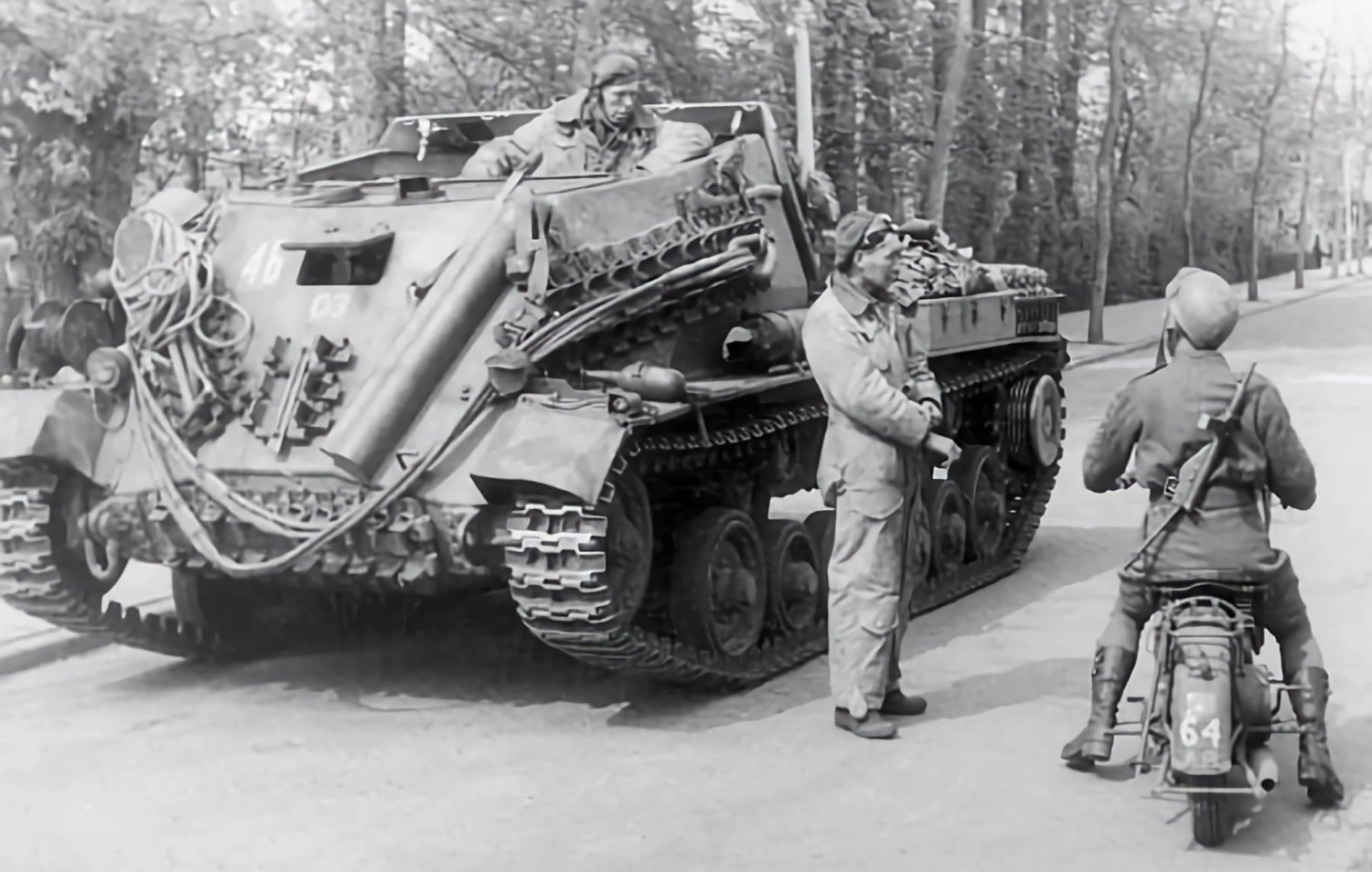
I’ve been basing my scenery on a few photos from a museum pdf file I found online. One colour photo in particular: According to the label on the package, the 4mm grass I used is supposed to be roughly 8” at 1/87th scale, so probably a little over 6”-ish for 1/72nd. Not much different in height from the grass these guys are lounging in. Admittedly, the grass in the photo is much more beat up than mine! Andy

-
P-51D Mustang by CDW - FINISHED - Dragon - 1:32 Scale
realworkingsailor replied to CDW's topic in Non-ship/categorised builds
Ed has some very interesting videos, his channel is well worth checking out. If you like the technical aspect, Greg’s Planes and Automobiles really dives into the nitty gritty of airplane performance, by the numbers (If you haven’t seen it already). He’s even done a recent set on human factors, why some WW2 planes are better than others from another perspective outside of performance. Andy -
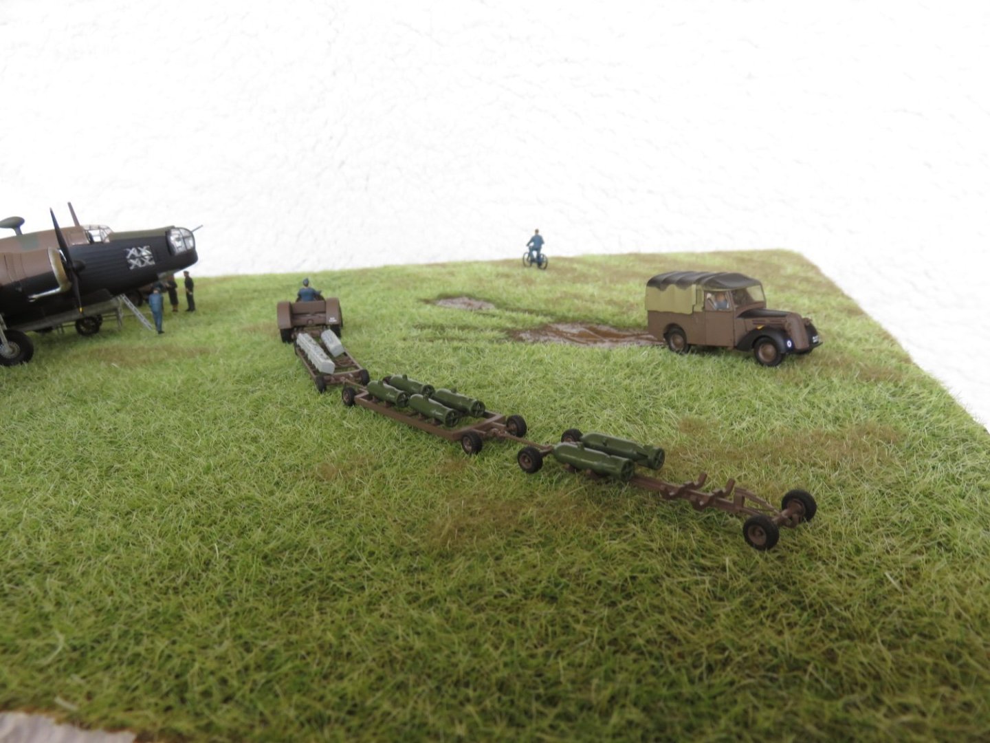
And like any typical public works type job, a suitable number of “supervisors” observing (there’s at least three standing behind the Bedford…..) 😜 Andy
-
P-51D Mustang by CDW - FINISHED - Dragon - 1:32 Scale
realworkingsailor replied to CDW's topic in Non-ship/categorised builds
Ed Nash did a great video on piston engined fighters. More than anything (agree with him or not), there’s a lot of caution needed when looking at an airplane’s alleged top speed: Andy -
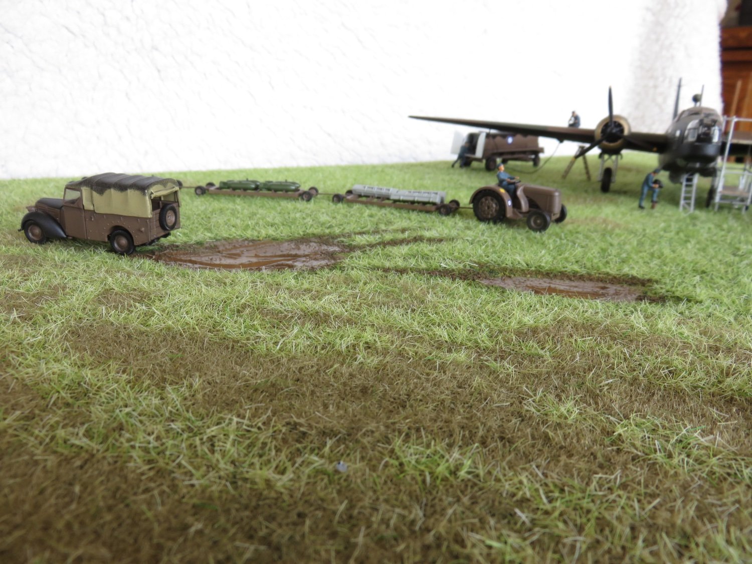
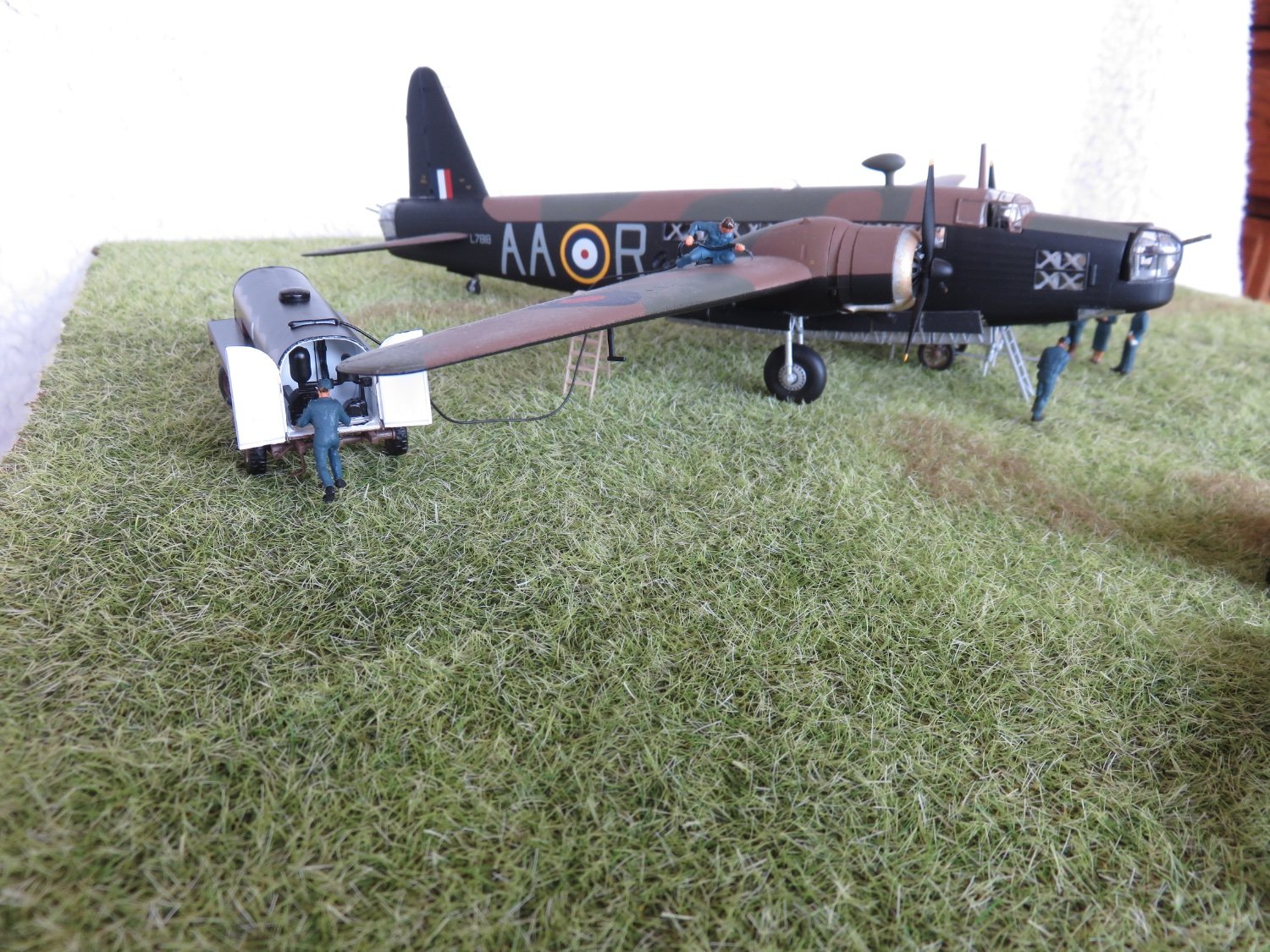
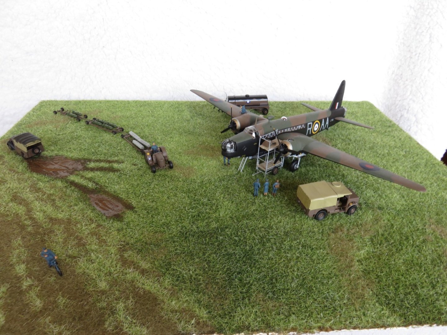
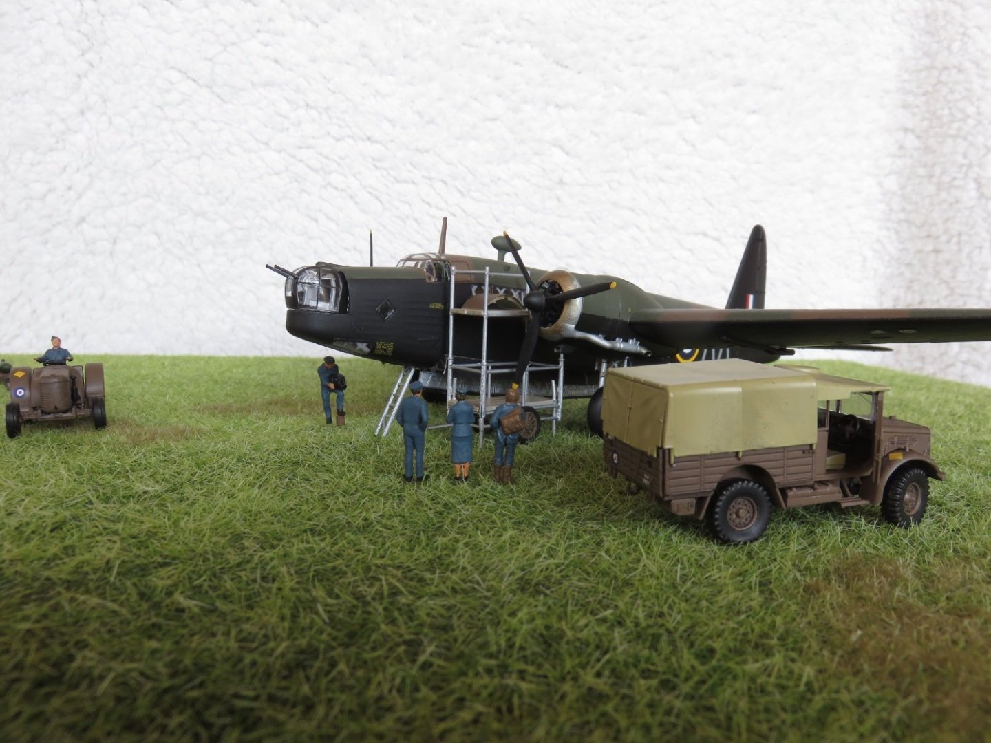
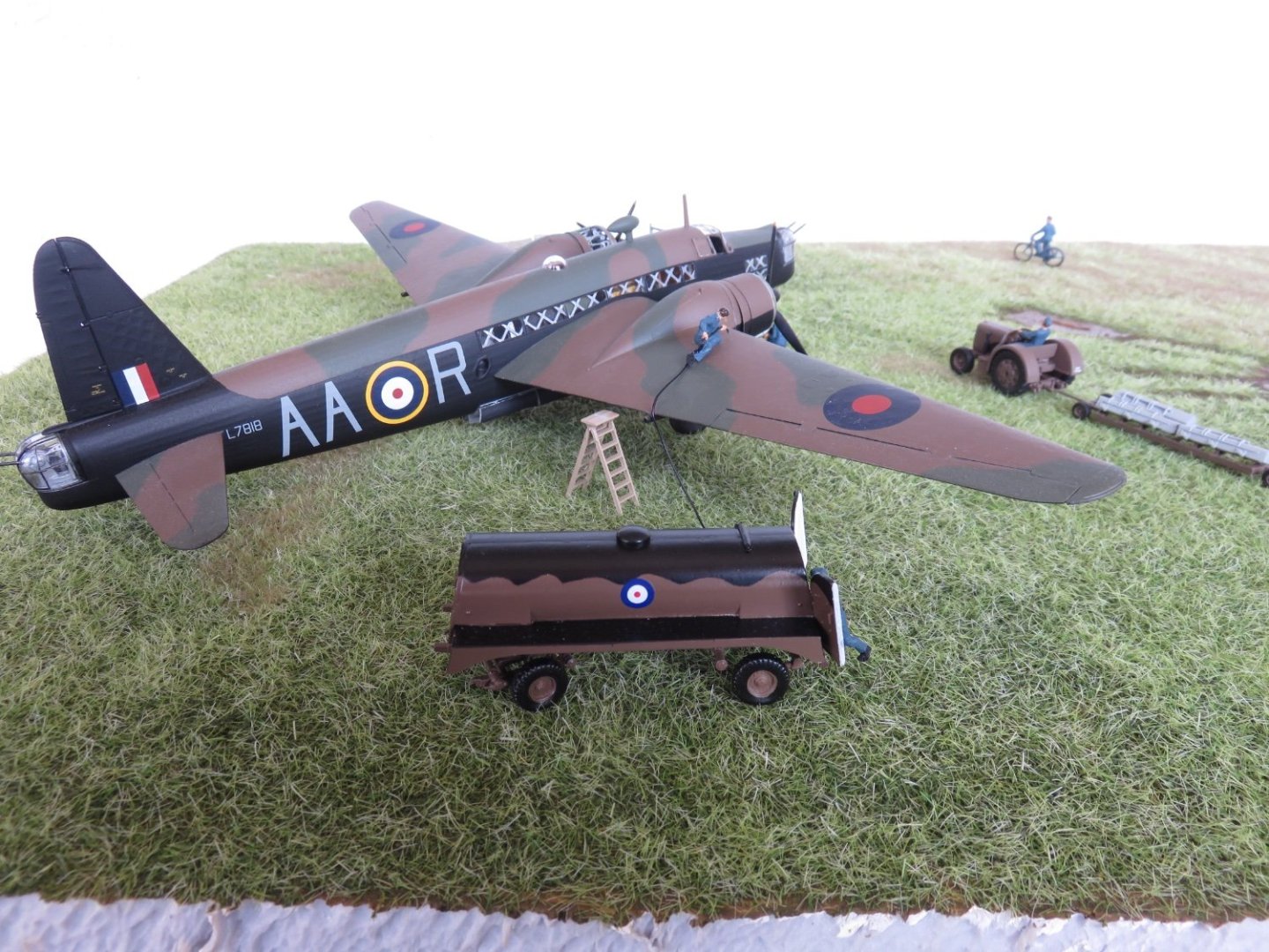
Thanks everyone for the kind comments and likes! Well, I think my grassy field is finished. Overall very happy with the way things turned out. There's a nice variation in the colour of the green grass , and I've added some patches of burnt grass to add some further colour changes in select areas. In the "runway" area I added more green grass towards the edge, gradually lessening the amount as I worked towards the hypothetical centre. All the characters have had their bases removed and a length of 0.012" stainless steel wire inserted, usually into one leg, and then into the scenery base, so they can free stand securely. I haven't added the mechanic yet, he will be glued to the trestle after I add a bit of weathering. I connected the refueller to the bowser with a length of wire. I kept the black rubber sheathing on, and it looks like a proper hose. Its a close enough match to the short length of moulded hose he is holding. I still need to add a few final details, touch up some paint work, and add a little weathering to the vehicles and other objects. But things are slowly coming together. Adding some "mud" to the back of the Tilly is going to be interesting..... I will also have to figure something out so the bomb train sits down in the grass, rather than floats on top of it... Even the other vehicles will need to be settled down a bit. It will probably require a little bit of delicate grass removal from directly under the wheels, we shall see what I can come up with. Andy


- 58 replies
-
- 13
-

-

-
I’m glad you haven’t thrown in the towel on this one yet! Andy
-
Are there lots of photos in the threads you view? I have an iPhone and while it does start at the “unread” line, as the photos load, the line gets pushed “down” until I’m somewhere in the middle of the page. Any thread I jump to without photos (or maybe one or two small ones) does start exactly at the “unread” line and stays there until I start scrolling. It’s likely a quirk inherent to Apple devices and systems, (how the web browser chooses to loads photos), and not something anyone here has control over. I may be wrong, but that’s my observation. Andy
-
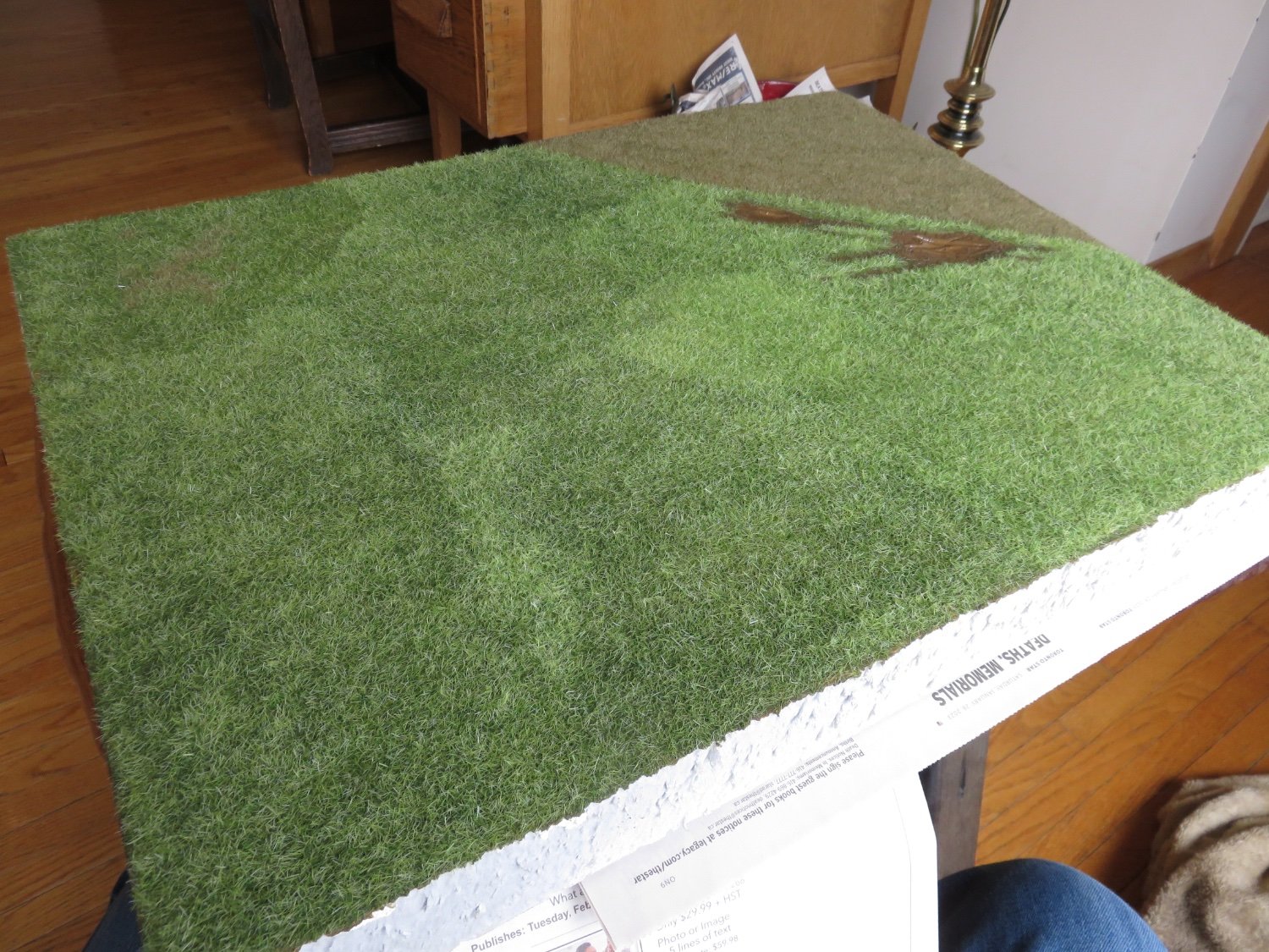
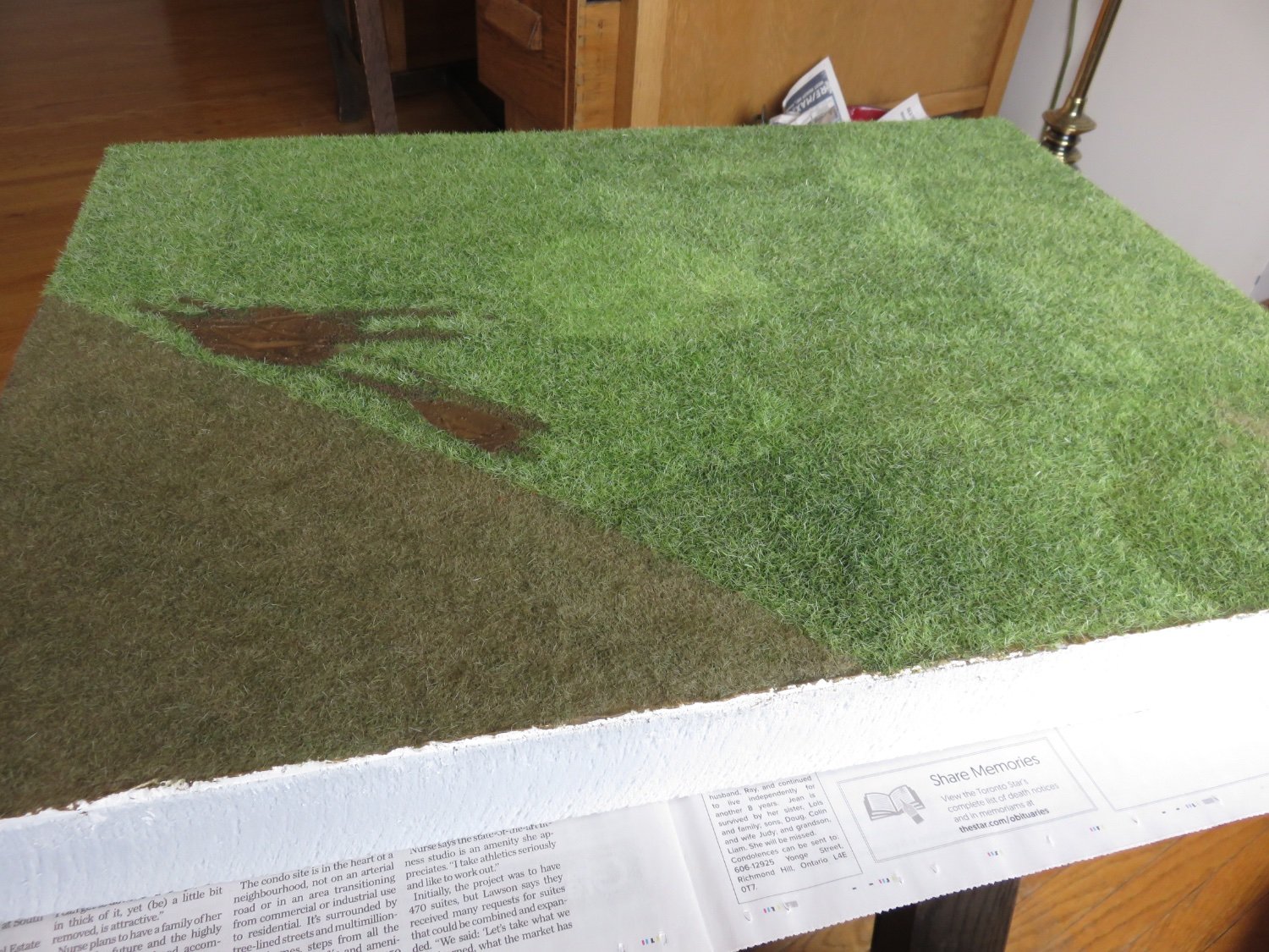
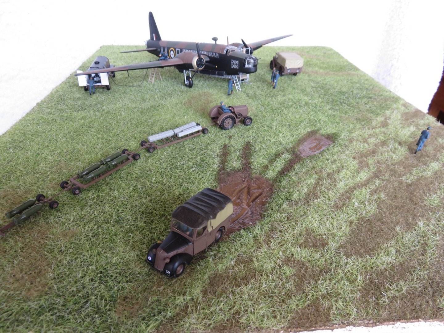
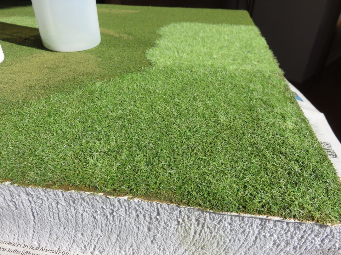
Thanks for the comments and "likes" everyone! Progress as of this morning: Surprisingly, it didn't take as long as I had initially feared after my first test areas, and I think I managed to do fairly well around the mud puddles. In that area, I used a small brush to apply the glue to the areas I wanted it, rather than risking dribbling it in to the puddles by accident. The line between the runway and the field is a little stark, but I plan to soften that by blending the colours in both directions when it comes time to add more layers of grass. I think the variation in the green colour is probably due to the inconsistency of the grass coverage, which isn't a bad thing. The darker areas are where the underlying ground foam is showing through somewhat. I think it adds a nice variety of shading to the otherwise uniform green. You can even make out a subtle under shading in the runway area where I had put streaks of green foam as well. Now it's on to blending, mixing and layering. Andy


- 58 replies
-
- 10
-
-
-
Thanks EG! It’s not without concerted effort… many times I felt like I was one flailing finger away from a green disaster… to say nothing of the risk of tipping over a bottle of diluted white glue…. Andy
-
Thanks Alan! We’re definitely on the same page here! After hand sprinkling, I would say this is the cheapest method, followed by the bug-zapper approach: Andy
-
Thanks Mike! It’s definitely precise, in that you can target the bottle spout into various nooks and crannies, rather than broadcasting the grass all over the place and hoping for the best. I think the key benefit over just sprinkling, is that it does impart a modicum of a static charge to the grass (one that builds up the longer one repeatedly squeezes the bottle), so the grass does more or less what it is supposed to do (stand somewhat upright). Andy
-
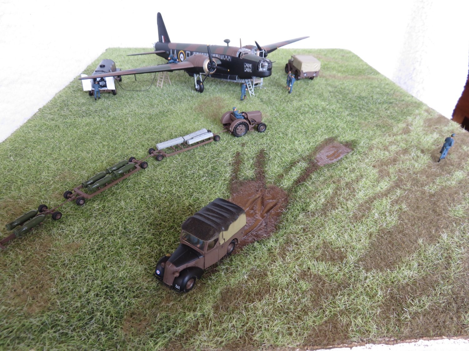
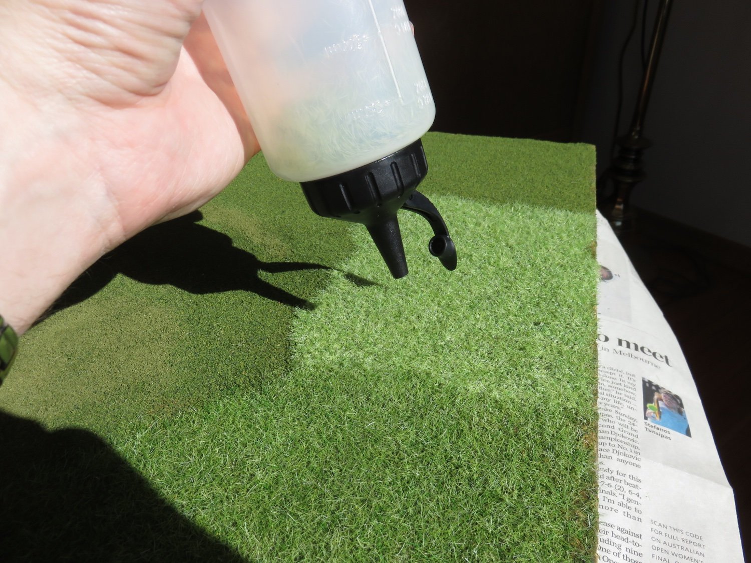
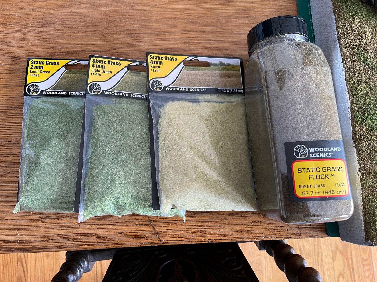
As always, I would be remiss if I didn't start by thanking everyone for your kind comments and "likes"! I've managed to make something of a start with the static grass. What a fun process it is! First up, the glue. You don't have to spend exorbitant amounts of money buying specialty glue. I made my own with some watered down PVA. I initially tried a 3 parts water to 1 part glue, but found I had to add a little bit more glue, so it's closer to 1.5 parts glue. I also added a few drops of isopropyl alcohol as a wetting agent (helps break down the surface tension). This was dribbled and brushed on to where I wanted to apply the static grass. I should mention that I don't have a static grass applicator... at least, not the fancy electrical variety. A few weeks ago I saw this video about someone who just used an inexpensive condiment bottle to apply static grass: So rather than spend a ton of money on a fancy grass applicator, or putting my electrical mad scientist to work mutilating a bug zapper racquet into a homemade Frankenstein-ian Van de Graaff generator, I decided to give this method a shot. It does work, and very well, but it does restrict to a small working area... there's only so many times I can rapidly "poof" a condiment bottle before my hands get tired! Don't fill up the bottle too much, about the amount you see in the above photo is more than enough, and it will cover a surprisingly large area (big enough that your hand will be start to cramp!). The results shown here are using 4mm static grass. I did try a test area using 2mm grass, but it came out too quickly and became somewhat clumpy. Not altogether horrible, but not the effect I was after. The repeated "poofing" action generates just enough static electricity for the grass to do its thing. The lighter area in the photos is just due to the glue having not yet fully cured. The ground foam underneath provides a great stable base and the state grass grabs really well, after letting the glue set up for only a couple of minutes. I have some "burnt grass" and "straw" colours that I will layer on later to add highlights and break up the monotonous green. For that I'm planning on using some inexpensive hair spray as an adhesive. From what I've read, the odourless "extra hold" stuff works just as well, if not better than so-called specially formulated static grass adhesive sprays. For the more well trodden areas, I will reverse the colours, starting with the burnt grass and adding green highlights. I should mention, that I have managed to keep the mess under some level of control... so far..... Andy

-
Not just at Verrieres ridge, but on the other side of Caen: It’s very fun, as a Canadian, to hear an American describing what the Canadians did. Andy
-
Compared to the countryside that the Americans faced, the area of Normandy that the Canadians fought was comparatively wide open. If I’m not mistaken, Mr Robertshaw is standing just above St. Martin de Fontenay. If you have “Breakout From Juno” by Mark Zuehlke, you can see the map for “Operation Spring”. Otherwise, let me know and I can pm you. Andy
-
Some goodies arrived today: Let the fun, games, and a hopefully not-too-unholy mess begin! Andy

- 58 replies
-
- 11
-
-
If that was in certain parts of Holland, or proximal areas of Germany, I believe there were a lot of pine forests in the region. A fair number of Canadian soldiers enlisted right out of the lumber camps, so chopping trees was a familiar activity. Andy
-
You may have seen this already, but if not: Andy
-
Thanks! The roughness of the foam is proportional to the roughness of the tool used to carve. If I had a hot wire foam tool it would have been much cleaner. I guess I could have carved recesses for the figure bases, but I don’t think I could have got the bases in any kind of presentable shape. The Airfix figures are moulded in a soft acetal plastic, akin to Delrin, and from a very old tooling… there’s lots of rubbery, hard to remove flash, and they really don’t take paint all that well, and if they do, they don’t tolerate any kind of abuse. I’ll hopefully get a hold of some static grass soon, there’s a model train show not too far away this weekend, I may poke my nose in the door for a gander; see what’s there. Andy
-
How about this: Lots of interesting pictures of QF 17 pounder guns here, including numerous pictures of Archers: https://www.silverhawkauthor.com/post/17-pounder-qf-anti-tank-gun Andy
- 47 replies
-
- 10
-
-
I’m not sure if the actual size of the parts, but it could be that the number of holes didn’t lend itself well to the injection moulding process. They may had had them to begin with, but the test shots may have had a high rejection rate. Andy
-
Looks like fun, count me in. Although he’s just started, @AJohnson is working on the 1:24 Typhoon, and he’s built a few other nice Airfix kits on here too, you may wish to check out his builds. Andy
-
Thanks Alan! I think it depends on the depth of water you’re trying to convey, or whether it’s still or moving (wind, waves or currents). WS products can produce some amazing “water” in the right hands. Andy
-
Not to worry, those obnoxious bases will be removed in due course. I plan on using a short length of fine wire to hold them in place (I have some nice 0.015” stainless kicking around). I will be adding some static grass next, so everything is just temporarily in place for now. I’m just waiting for the hobby shop to restock what I need. Andy