Ras Ambrioso
-
Posts
662 -
Joined
-
Last visited
Content Type
Profiles
Forums
Gallery
Events
Everything posted by Ras Ambrioso
-
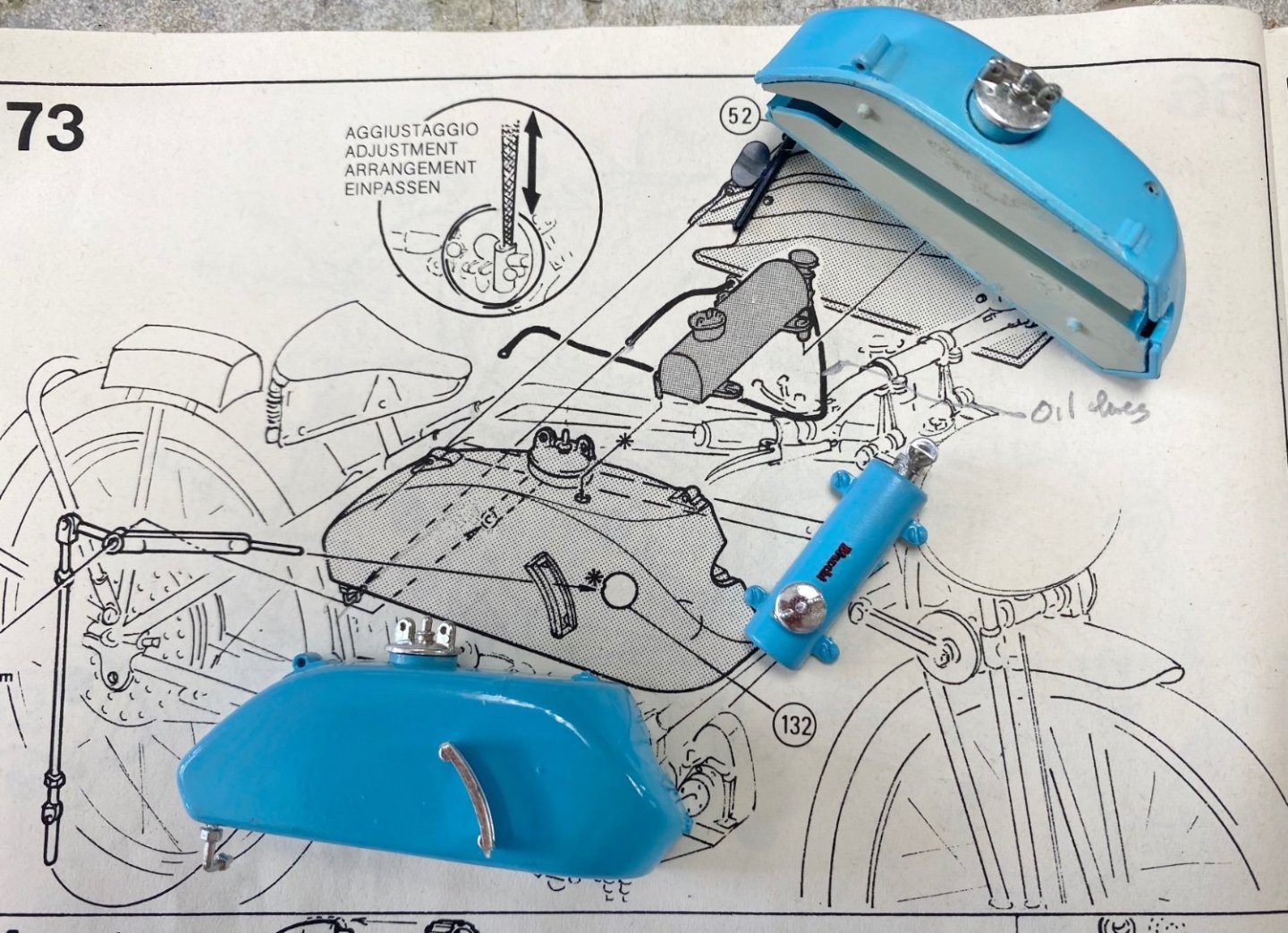
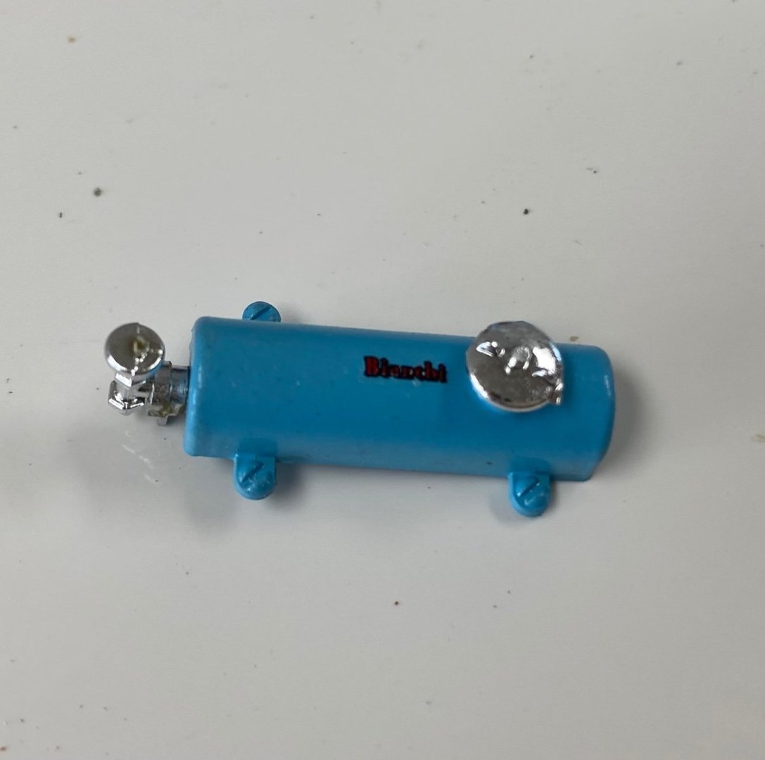
 I have been scratching my head about the little blue tank on top of the gas tank. I have thought that it was part of an oil drop lubrication system. But, today, I looked again at the piping diagram in the instructions and saw that the hose from this tank was going directly to the carburetor. Then I remembered that, in my engineering days, I did a project in Venezuela building an MTBE plant in one of their refineries. MTBE was used as an additive to gasoline to improve the octane which is adding oxygen to the fuel. This chemical was popular for a time( the 70's) but was a dangerous and expensive process and it was substituted by ethanol, not as effective but much cheaper and abundant. I can imagine that during the 20's racers were always looking how to improve the efficiency of their machines and used these kind of additives. So, I think that little blue tank was feeding some additive to the combustion to improve the performance of the engine. Also, since I already increased compression by reducing the cylinder height, I am sure that the bike could really use another little boost and Freccia Celeste will be as fast as a "bat out of hell. LOL😂😂😂 Any comments?
 -
Valeriy, happy to see you are back in the forum. Looking forward to this build.
-
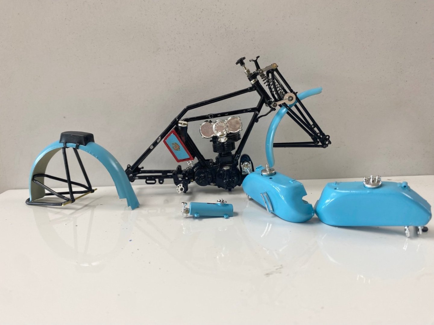
The Bianchi is starting to look like a motorcycle. The bike has two fuel tanks that straddle the bike's frame. The separation of the fuel tanks was done to prevent the fuel from shifting to one side on curves, thus affecting the bike's stability. The third little tank on top of the fuel tanks is, supposedly, another oil tank that is to be piped to the cylinder double overhead camshaft (DOHC)and is used for "drop oil lubrication" (as per Wikipedia). I am interested in your comments about this tank. Next I will be installing all this equipment in the frame and touch up some of the damage that resulted from the assembly. And then I will go to real challenge of this project : the spoke wheels. And after that I will add the piping and wiring. The kit furnishes black rubber material but I think I will use electric wire with different color of insulation to identify their purpose. And that will be the last challenge.
- 126 replies
-
- 11
-

-
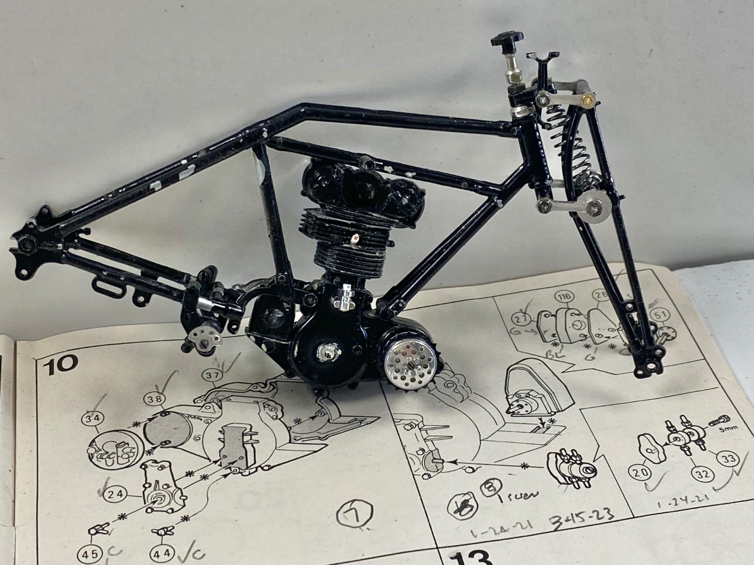
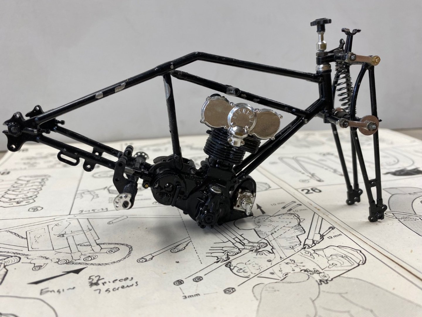
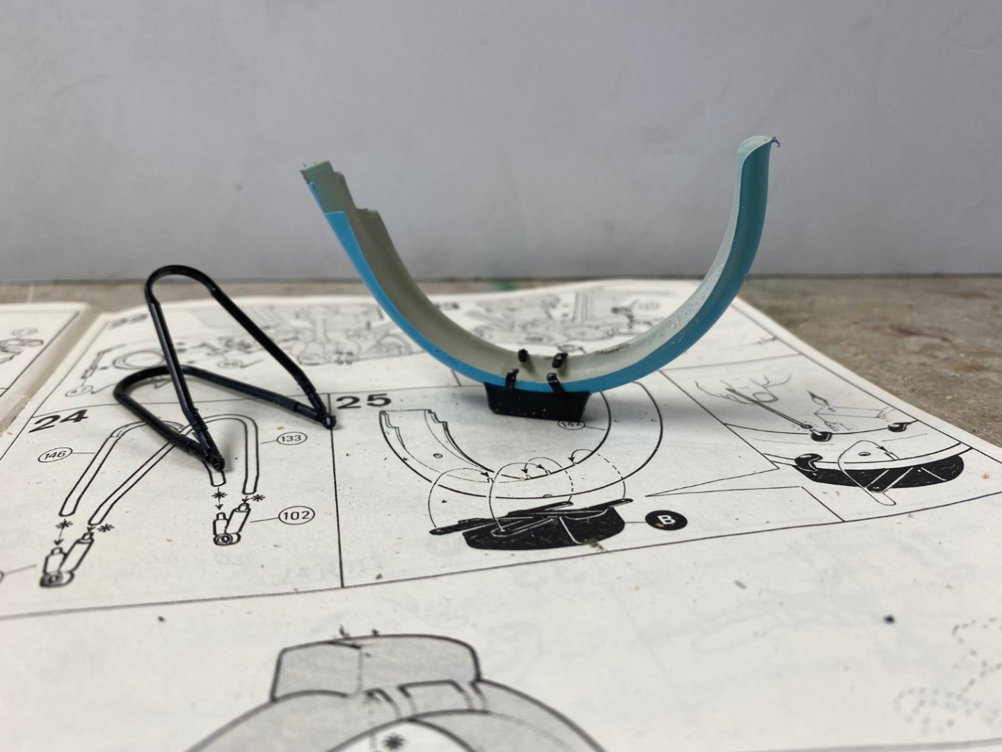
Well guys, thanks a lot for your comments and support. Today I went back, after a good night's sleep, and turned the engine around. It was much easier than I thought thanks, in part, to the fact that the sides of the frame were not yet glued, only screwed. Yves, the picture you posted made me cry. Kim is definitely a master modeler comparable to Valeriy or Wefalk in our ship modeling. I hope my Bianchi comes out as pretty. In looking at Kim's Bianchi, I can see how tight the engine fits in the frame. Following is the result of todays work. I took the picture over the instruction sheet to show you how easy it looked in the print. Next time I will be a little more careful in analyzing the kit parts before blindly starting the assembly thinking it will all fit. More details have to be added to complete the engine. To make me feel better, I went ahead and assembled the rear fender. Again the little pins to secure the rear seat (????) were too short and I ended having to glue each strap to the pin stub.

- 126 replies
-
- 12
-
-
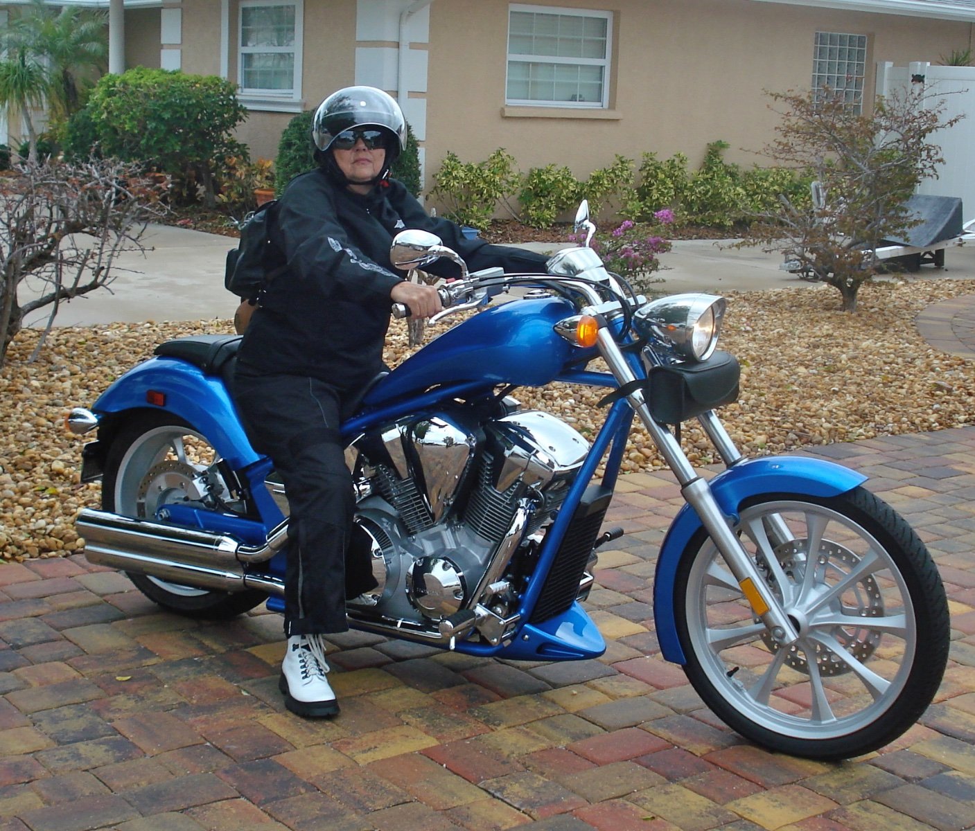
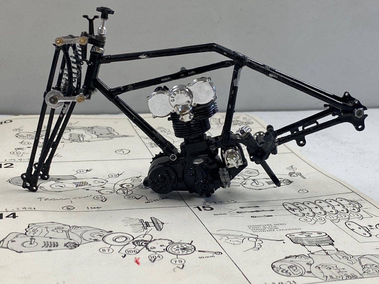
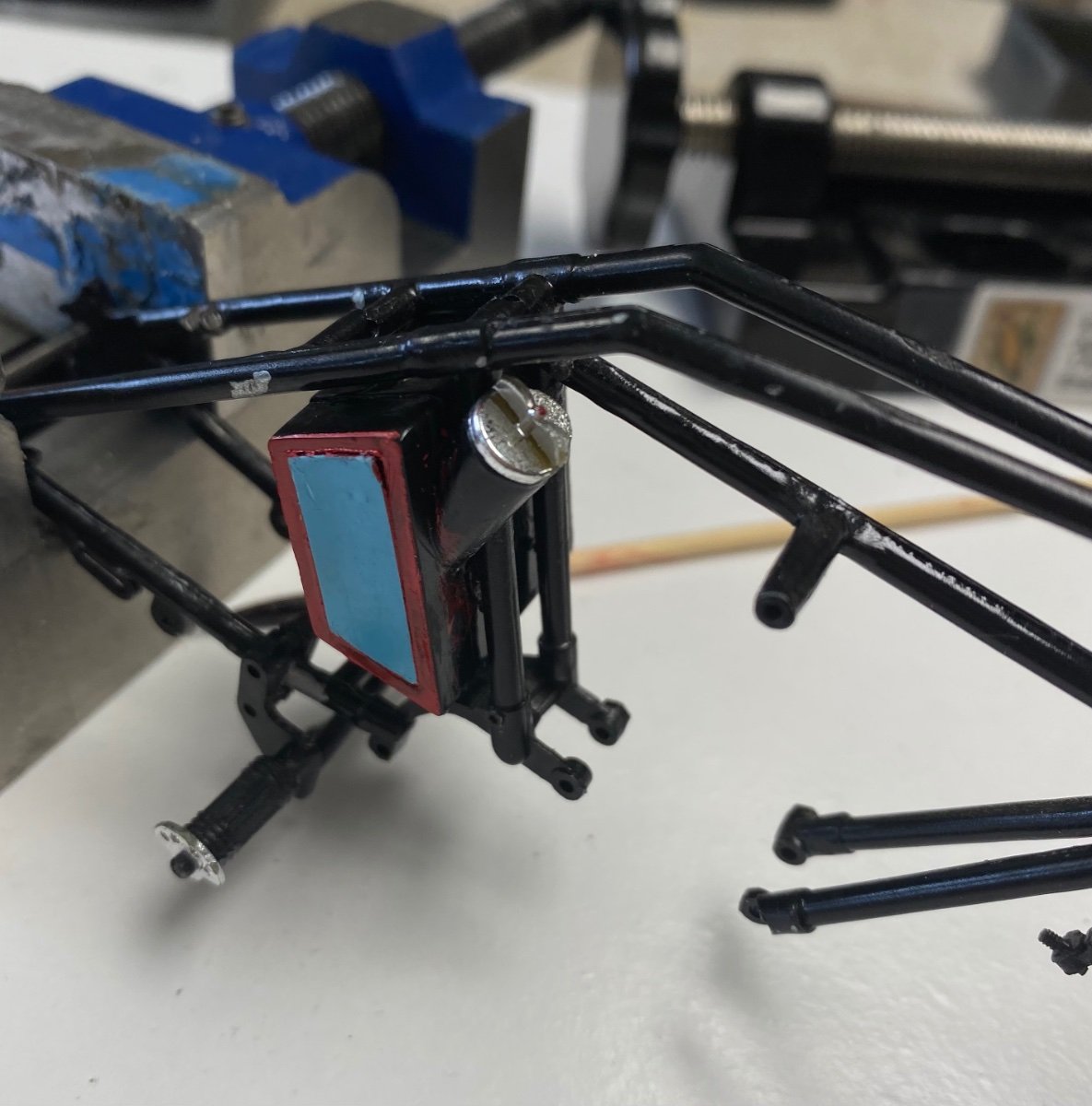
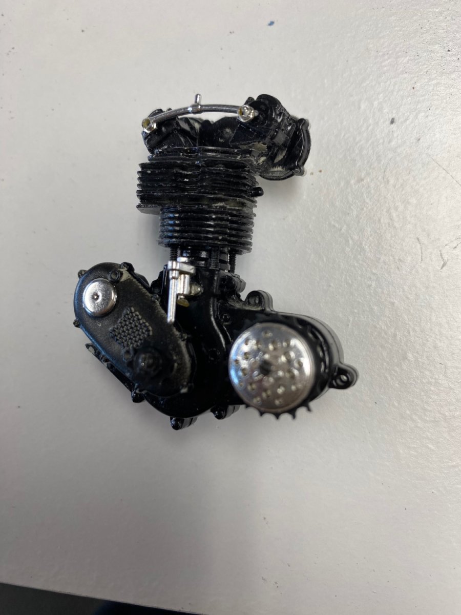
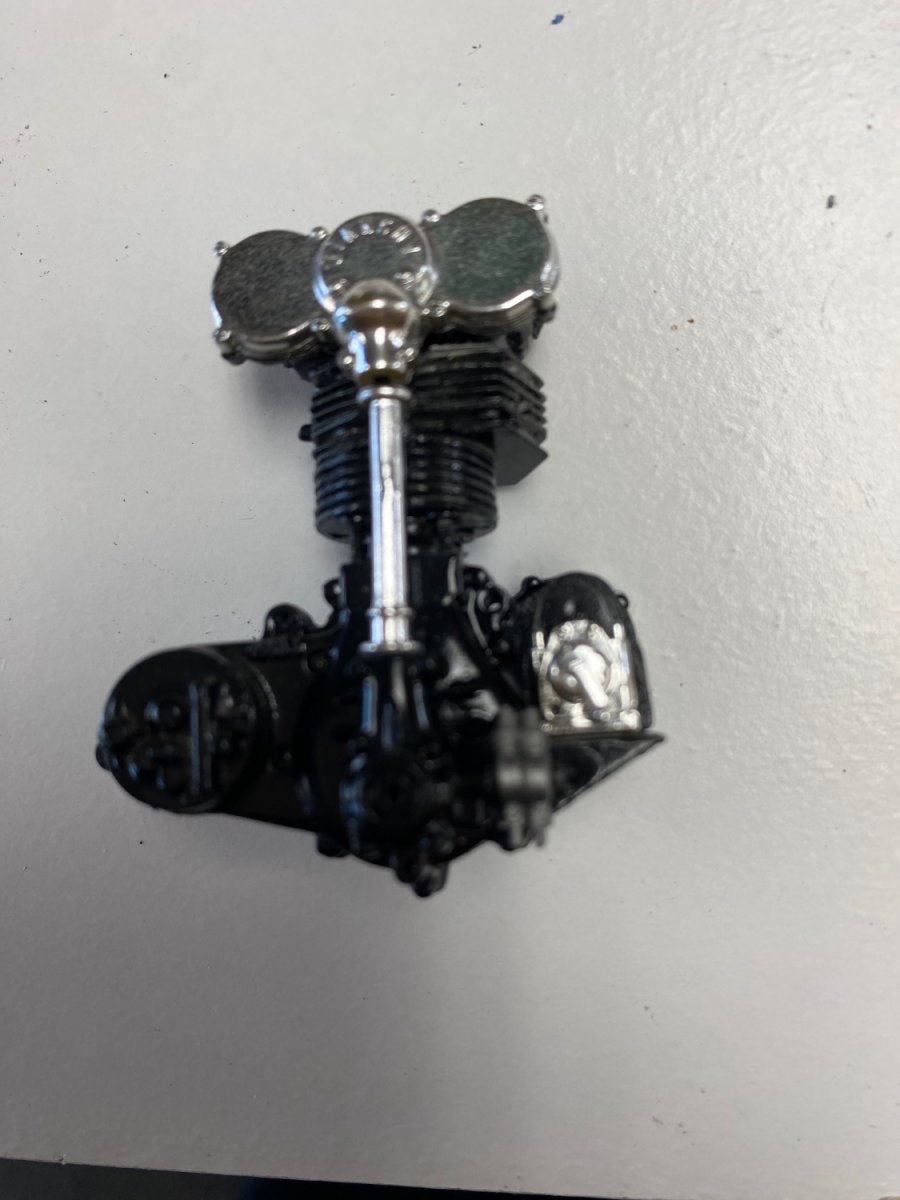
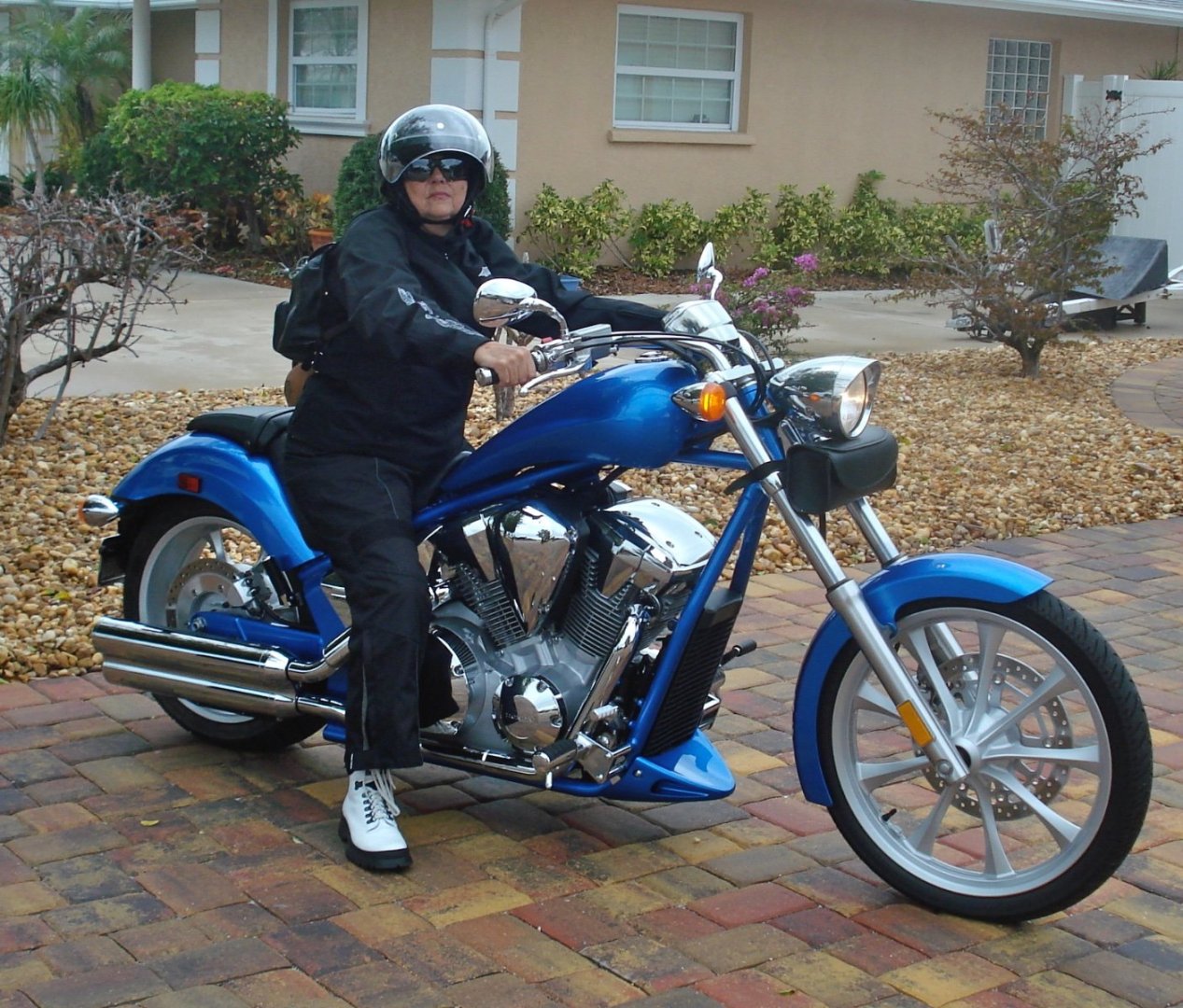
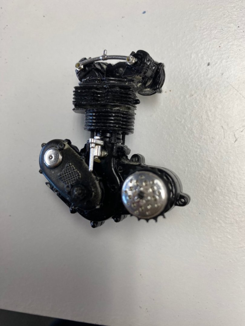
Pretty bike. I have owned three Harleys, the last one being a trike as I was getting too old and unbalanced for two wheels. I truly enjoyed riding them. However, in the Florida summer, they are hot as hell on your legs. My wife, who still rides, had two Harleys one of them was impractical jewel: a Honda Fury. I say impractical because the gas tank held less than 2 gallons that gave it a range of 10-15 miles and also there was no way I was going to ride in the back. But, lets get back to topic. Today I reached the top of frustration. After spending close to a a week (roughly 15 man hours) with more, filing, sawing, sanding and cussing I managed to place the motor in the frame. So, you will say, whats wrong with ? If you look closely, the driving sprocket is on the right side of the frame. Horror 🤢🤢🤢 So, is back to bench to an easy fix since the engine is supported with screws. Thanks God. Previous to this, I had installed the oil tank in the frame. It came loose while doing the motor installation. Following is how that looked. You can notice how my pre-painted frame has suffered all this handling. Touch up will be required but the bike now looks "weathered". LOL


- 126 replies
-
- 13
-
-
Keith, I had the same thought while sawing off the “extra” fin.
-
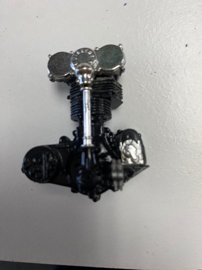
Hours of pleasure yes but, you are right, the kit parts are not as accurate as they should be and that is creating problems in the assembly. The engine assembly was in three parts,: the cylinder, the head and the overhead cams enclosure. When assembled (see post #33)the total height of the engine was off by close to 1.5 mm of the required height to fit between the mounting bolts and the the bottom of the gas tank support bar in the frame. My solution was to file off one of the cooling fins lowering the head. Now I need to counter sink the cylinder bolts so that the head sits flat over the cylinder. Hopeful that will work. Will keep you all posted.
-
Shipman, those bikes are gorgeous.
-
This motorcycle engine is a jewel of details. It has 52 pieces and puts it together in 6 sub-assemblies provided with holes, matching pins or mini-screws. It was a real challenge trying hold these separate pieces while using the superglue or the screwdriver or both. Also the pieces alignment was necessary but, the kit itself was, in some places, was inaccurate. So there was a lot of filing and cussing. Finally it all came together ,I think, in a nice way. The photos are not of the best quality because, by the time I took the pictures I was exhausted . And there is still more to go in this engine so I will keep you all informed
-
The kit has a mix of materials. The frame and suspension are metal. Then there is black plastic, grey plastic, chrome plastic and finally rubber plus the metal screws and nuts in 7 different sizes and a sheet of decals. A little bit of everything. The first kit I bought in the 90’s was new but this one was bought from a modeler that probably got frustrated at the difficult assembly. I will check the box and the literature to see if there is any information on the date of the kit.
-
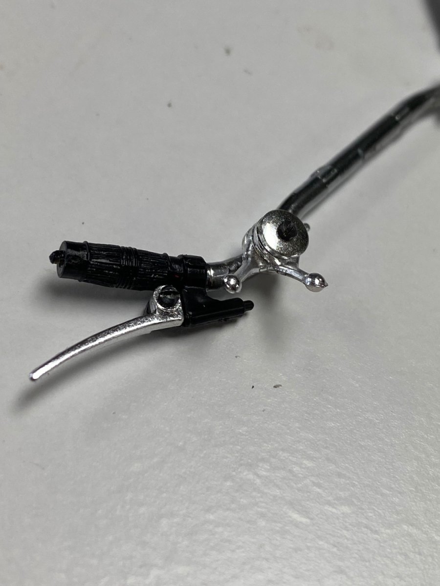
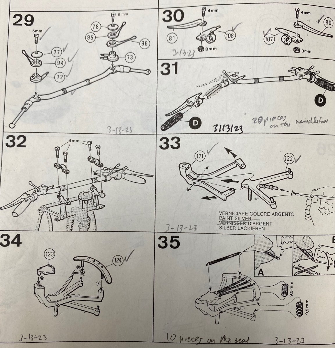
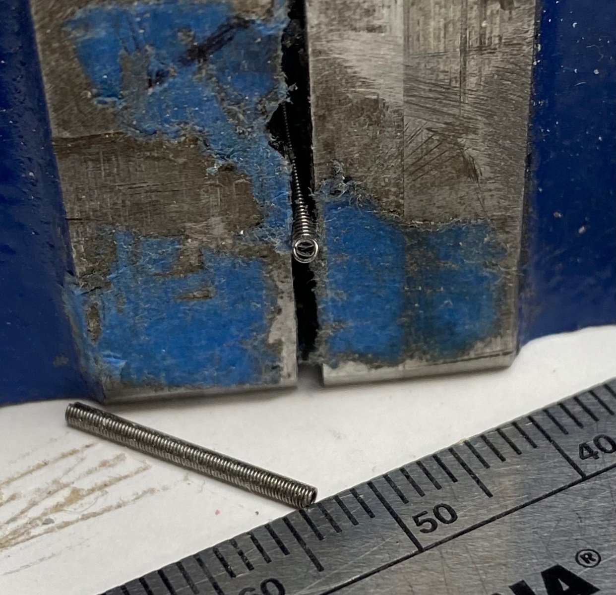
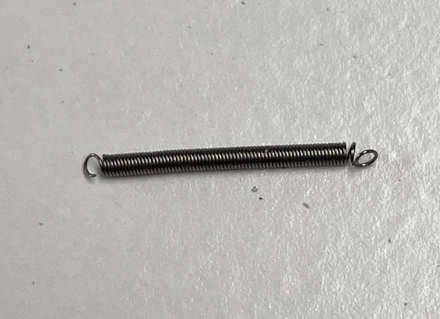
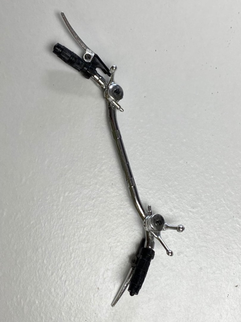
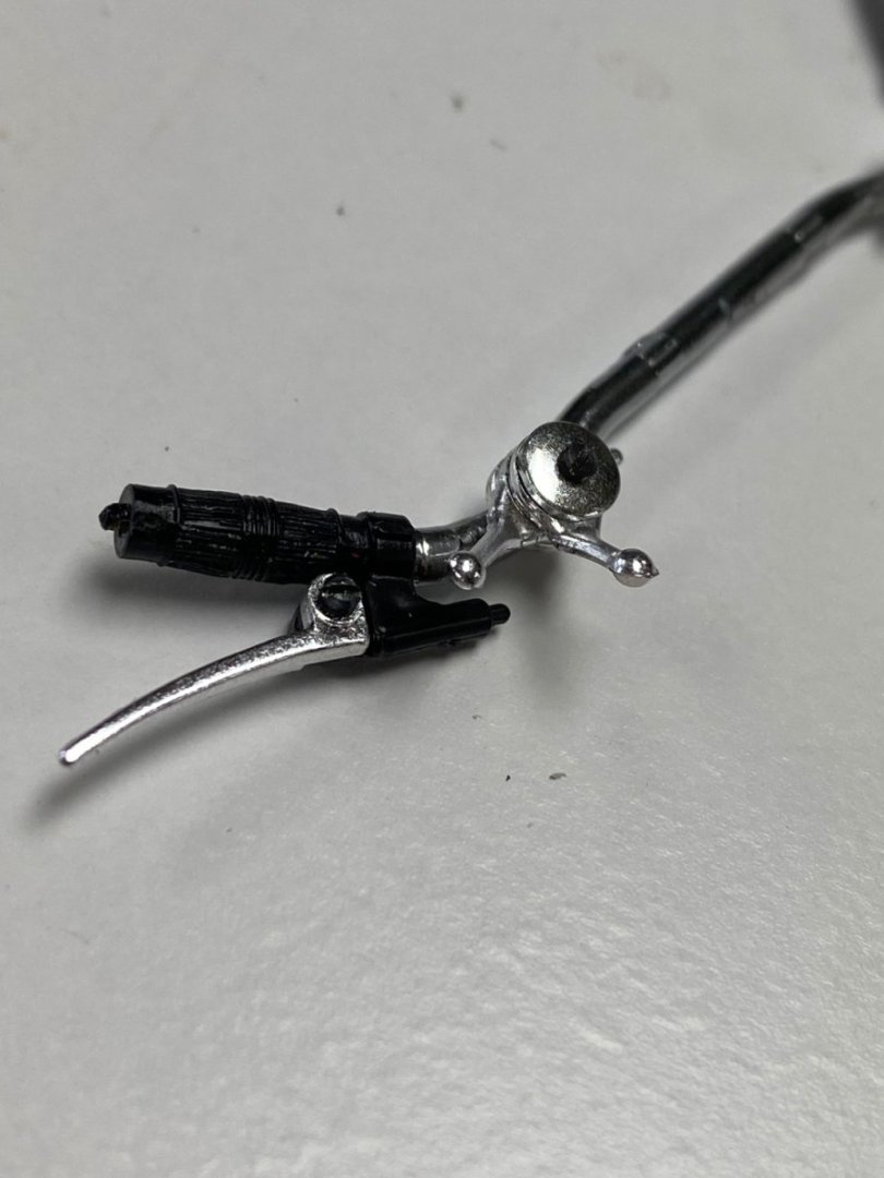
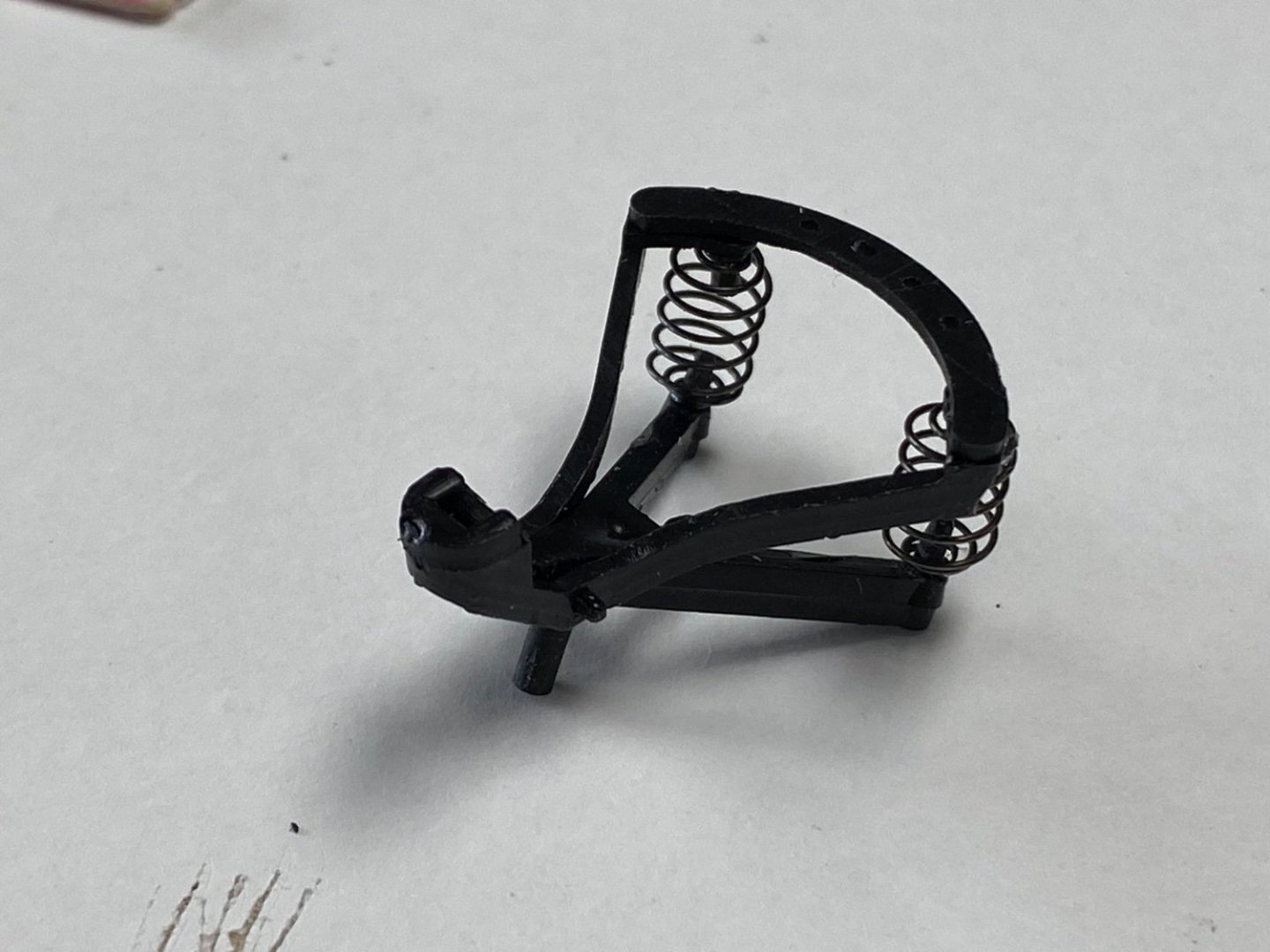
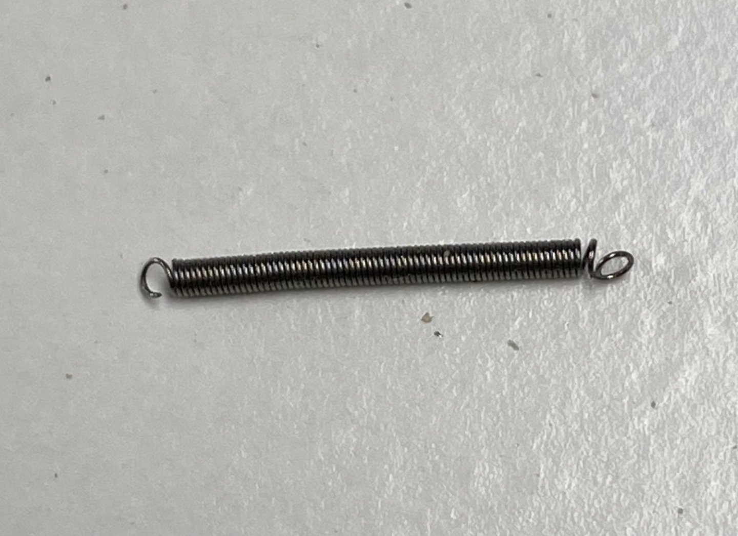
Guys thanks for the comments and the likes. This kit is getting to be a little more difficult than expected but I am determined to finish it. Today I painted the engine parts prior to assembly. Also worked on the handlebars. A total of 20 pieces. I was amazed at the detail on this kit. The handle is actually rubber Following is a print of the directions so that you can see the number and the rather simplistic way of suggesting the assembly. Next went the seat, also super detailed. The seat will lay over four mini springs, about 1.5 mm in diameter. Loops were to be made in order to hook the springs to the frame. The instructions indicated how to make the end loops to mount the springs. No way Jose. It was quite a difficult task as the spring doesn't like to be bent. I finally sort of made it by holding the body of the spring in a vise. The result was not very pretty but, again, it will not be visible since the leather seat actually lays on top of the springs. Boy, am I having fun or what? More tomorrow.


- 126 replies
-
- 10
-
-
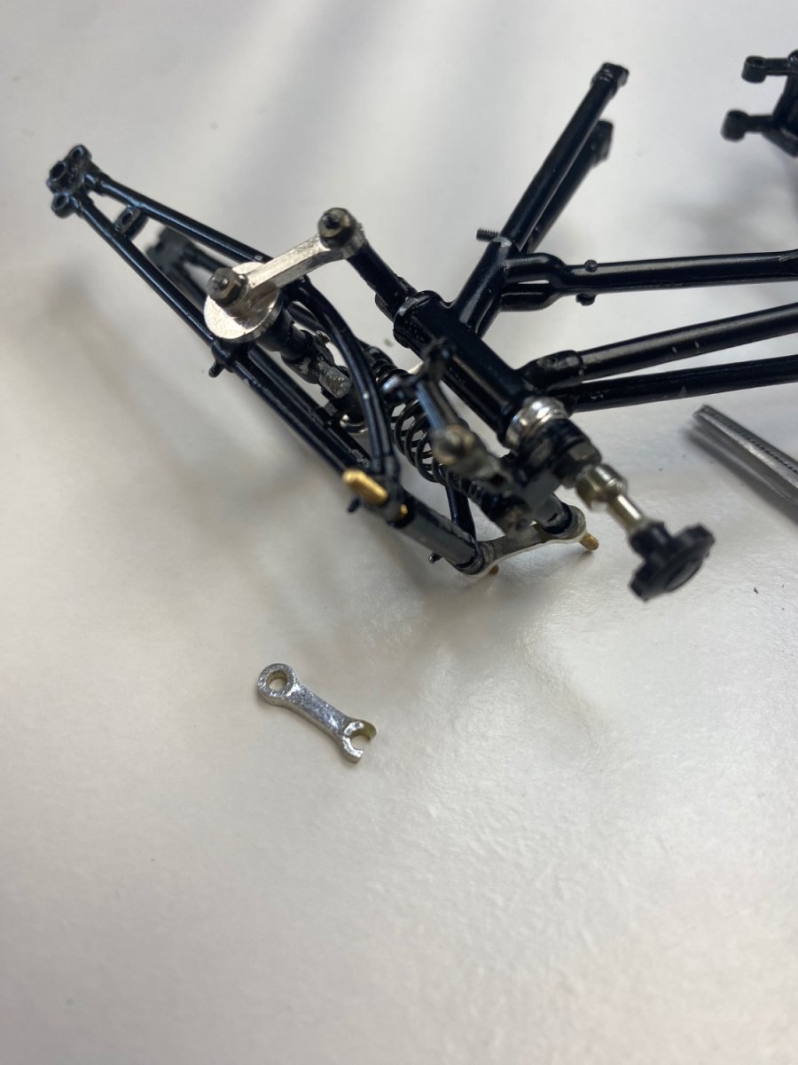
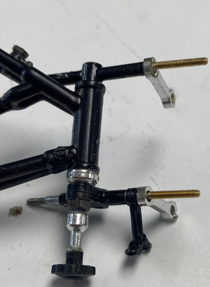
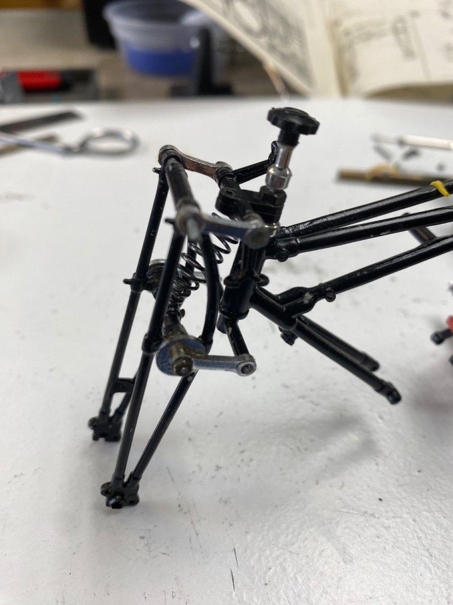
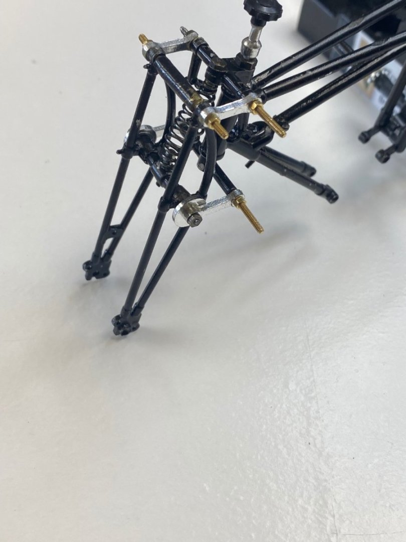
All of last week I have working on the front forks. First, I tried to tap the screw threads on the blank top axle. Tragedy, as suspected, the metal would not take the torque of my hand powered die and broke. Then I duplicated what I have done on the lower axle and fabricated a new axle, drilled the ends, and attached the screws to it. When I tried to re-assemble the forks, more trouble came my way as one of the links broke during the assembly. Horror! By this time I was running out of wind and had the awful thoughts of quitting this build. I stopped, went across the street, and got me an expresso. I returned to the shop thinking about the other two times (in the 90's and in 2021) that I had quit this same kit, and decided that, this time, I was going to complete it. I was going to fabricate a new link but then I noticed that the break was only at the top of the link and there was a good 270 degrees of contact in the bearing surface. So I went back to assembling the fork with the broken link. As you can see the fork came up alright. The projecting screws were trimmed and everything tightened up. It is a fragile assembly but, I am certain that this suspension will not have much roadwork once I place it in my shelf.
- 126 replies
-
- 11
-
-
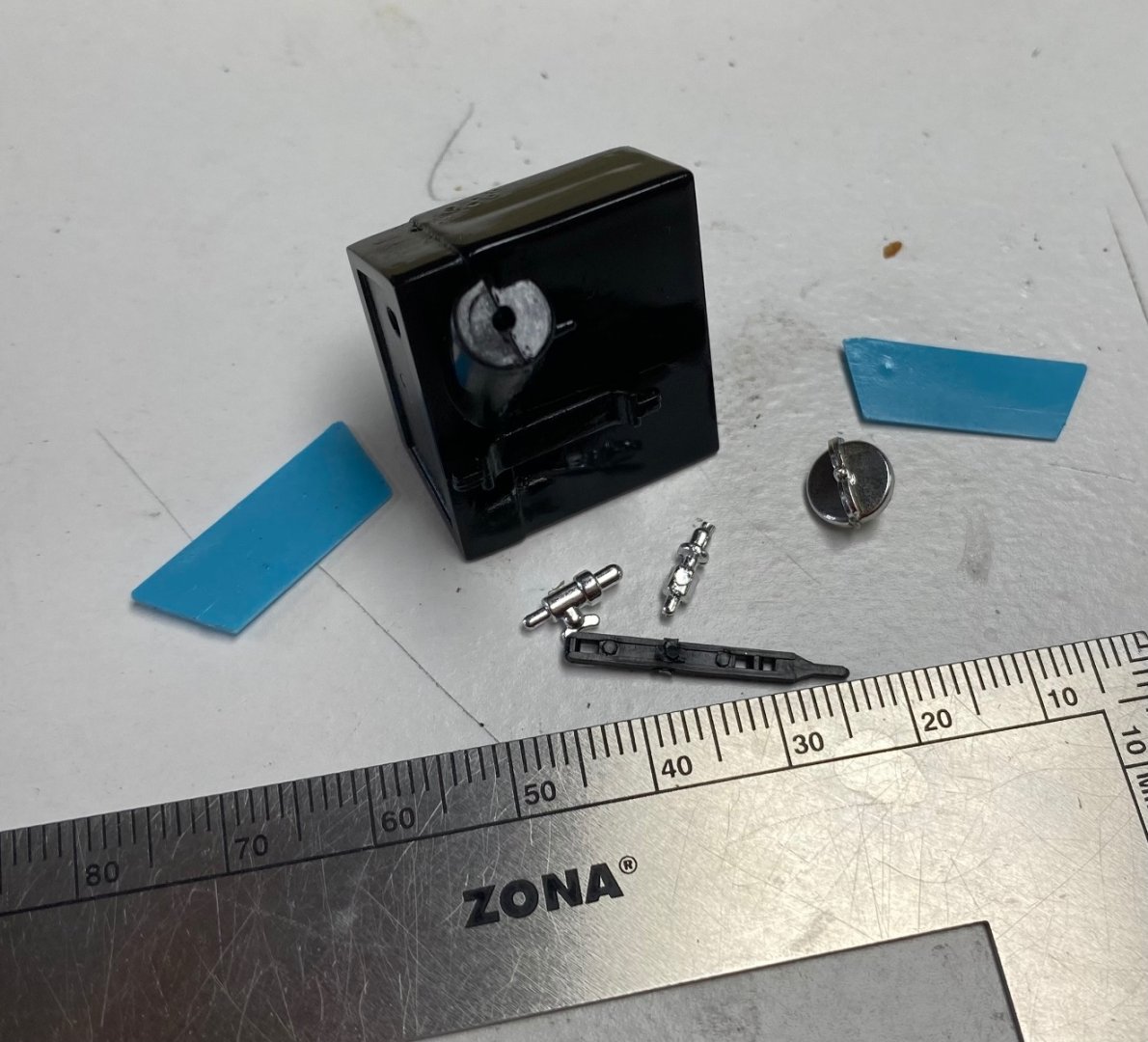
Guys, I haven't finished the motorcycle and you are all getting me excited about a model of the swordfish. The motorcycle is coming along slowly. I got the dies in the mail and tomorrow will be trying the tapping the axles in the front fork.. Today I worked on the oil tank. these are the parts before assembly. Notice the small fittings for the oil. Amazing detail.
- 126 replies
-
- 12
-
-
To CDW: When I was closing my last post I saw your list of finished models and found that you had made a Fairey Swordfish model in 2019. I just happen to have finished reading a book about the British raid to the Italian fleet in Taranto Italy in WW II. This raid was done with Swordfish torpedo bombers. These planes were also used to sink the Bismarck and, being an open cockpit biplane, it was hard to imagine such airplane in a modern war.
-
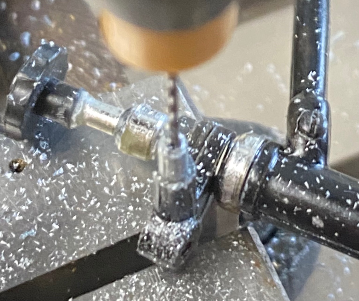
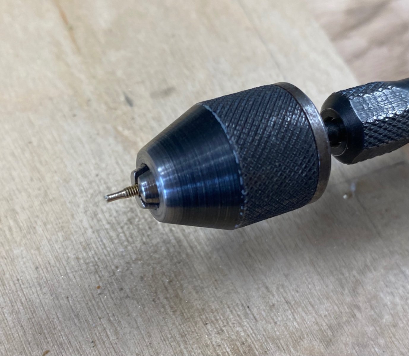
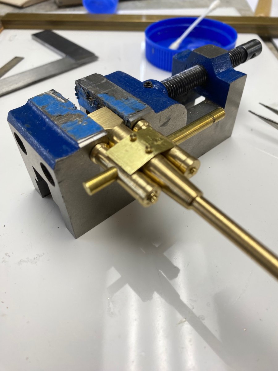
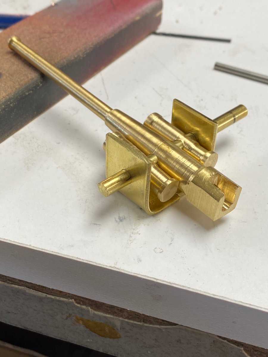
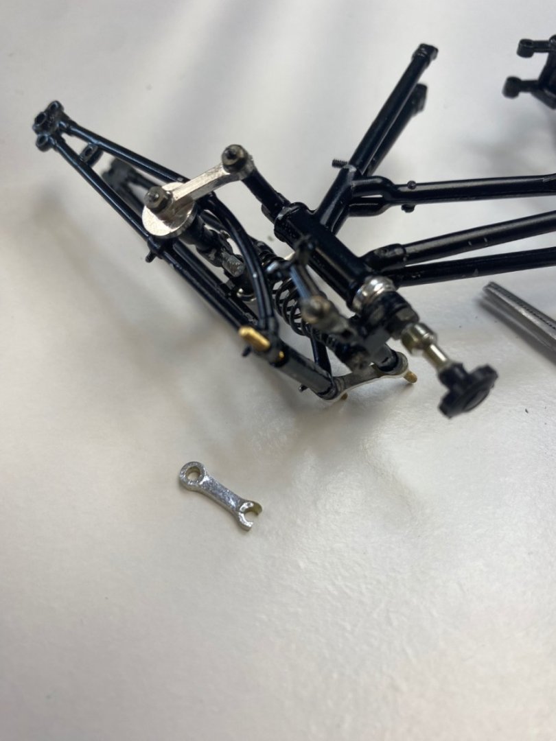
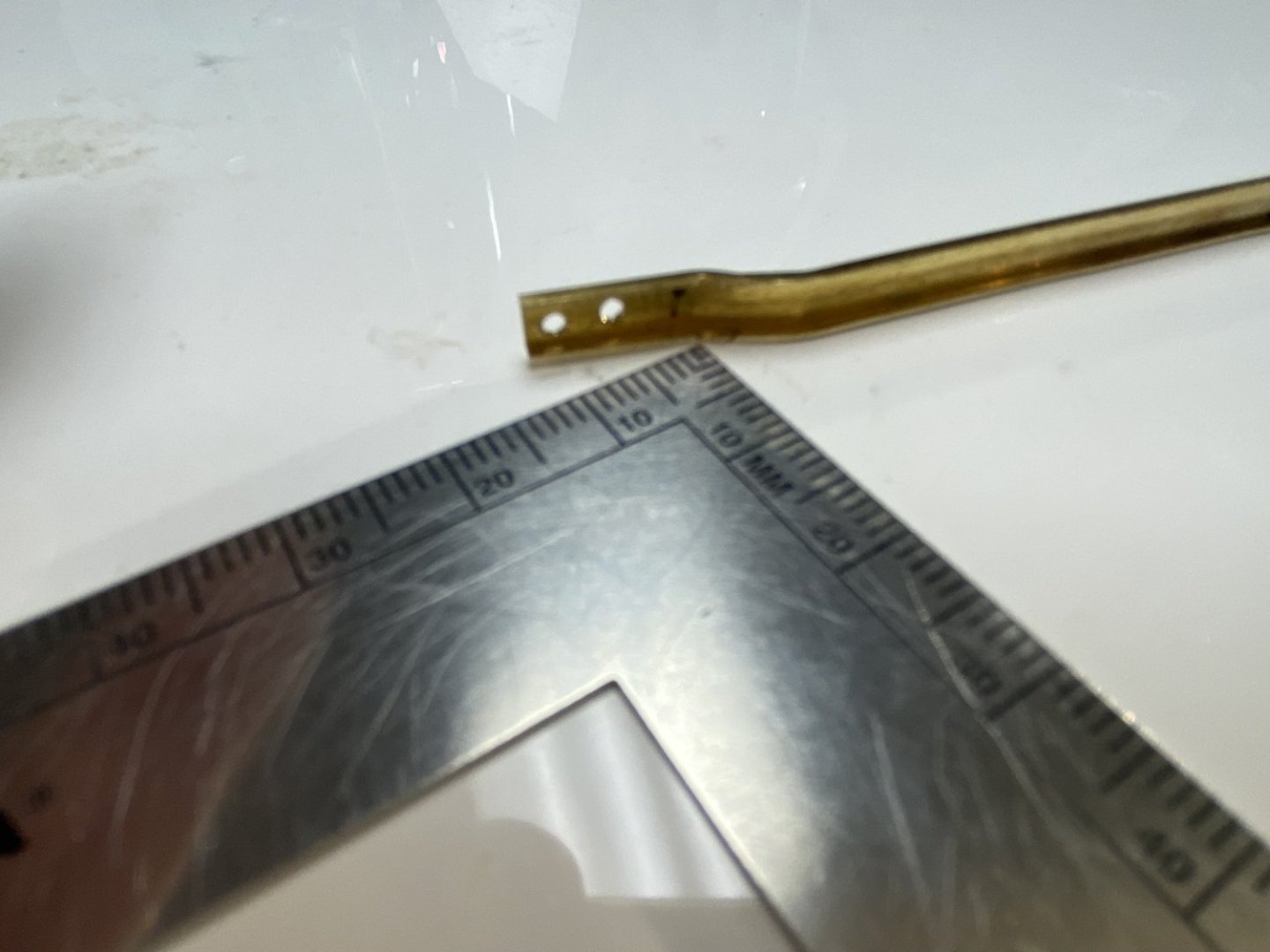
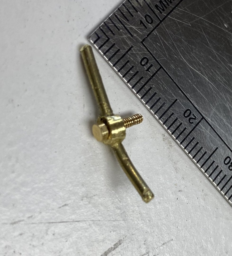
Today I went back to the front forks of the bike and figured what to do to repair the current damage. The first problem was the fact that some of the axles for the connecting rods were plain (without the screw section). To solve this I opted to order a micro set of taps and dies. The second problem was to secure the connecting rods where the screws were broken up. Soldering a piece of rod would be difficult and I am not sure if the kit's metal can be soldered. After a little thought, I decided to go and attach a threaded rod using a stud drilled into the axle. To do this I needed to drill a 1.0mm (0.040") hole in a 1/16" (0.0625") axle. This was getting close to my minimum tolerance. So here was my setup. Then, using my Dremel, I turned, with a file, a 1mm stud at the end of a headless 00-90 screw. And this is the dry fit on the axle. In fact I am not sure too sure I could tap the axle metal. And, in that case, I will do the same for that other side.


- 126 replies
-
- 12
-
-
To CDW: Thanks for the information. I will probably join the IPMS. I have done a lot of plastic modeling through the years but what I like about our ship modeling (wood or other materials) is to be able to build the parts. I could never reach the point of reaching the accuracy of the plastic models in the market today.
-
CDW, We are almost neighbors. I do not belong to IPMS but would appreciate information about it. It used to be we had a few hobby shops around where we met guys (or gals) with similar interests and exchanged information. Unfortunately, they are all gone and we only have the craft shops like Michaels and Hobby Lobby. I do most of my shopping online and use this forum for information.
-
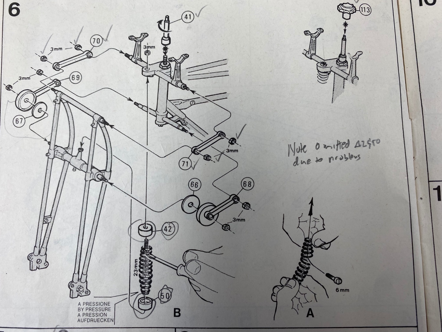
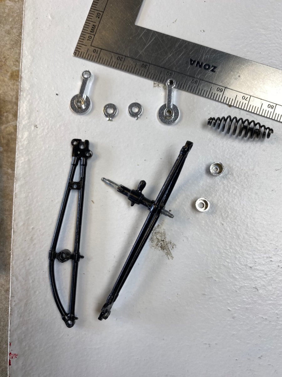
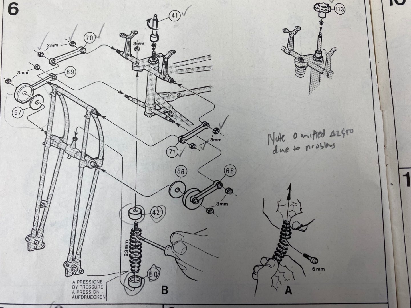
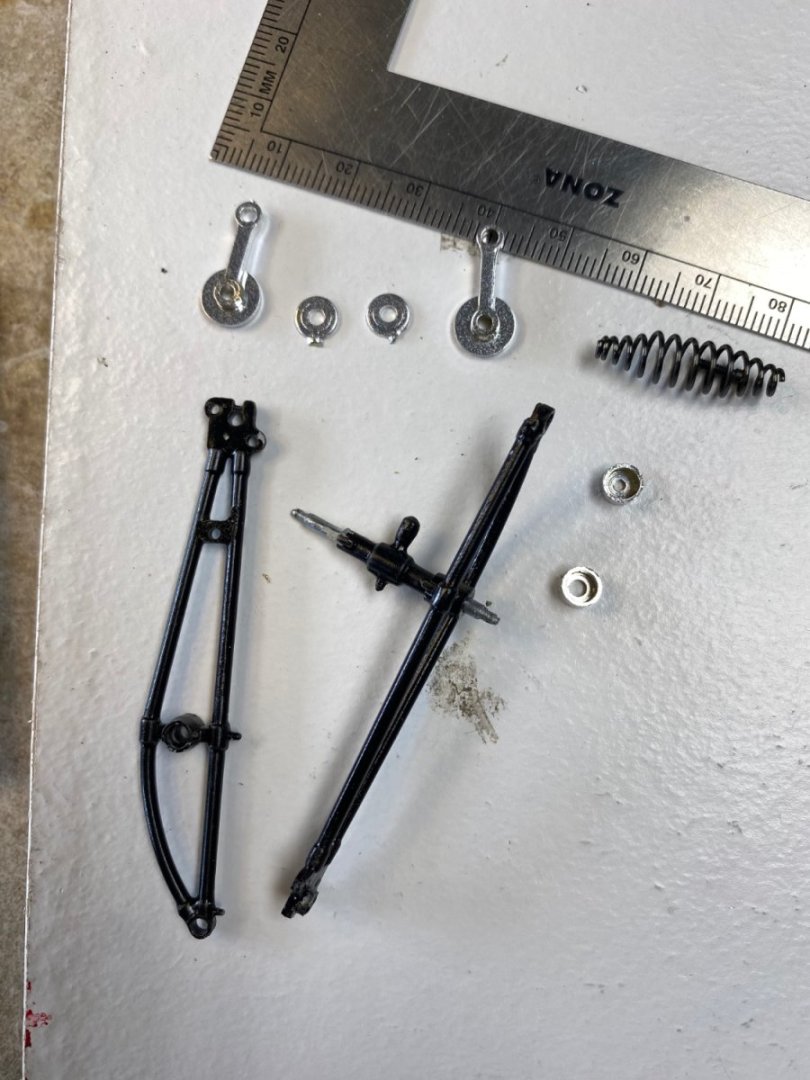
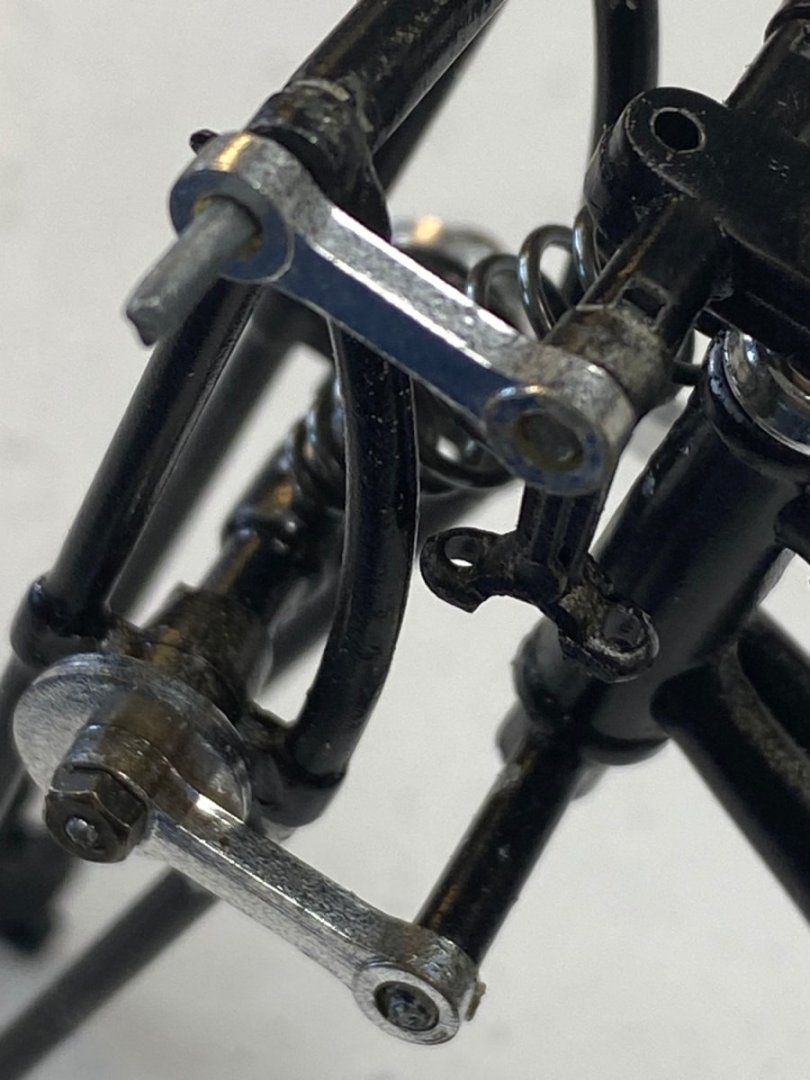
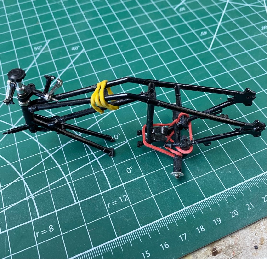
Now I remember why I quit this project twice in 30 years. It is damned difficult. The kit is beautifully presented and the instructions are very clear. Notice how pieces 68,69,70 and 71 will form a parallelogram. The spring will be inserted between the frame and the fork and everything tied and tighten nicely. Wrong! This is the beginning of the assembly of the front wheel forks. And this is the parallelogram after a dry assembly that required five hands to keep straight Looks Ok, right? Oh No. If you look closer you will get this Bottom left connecting piece went on right but, top left was not tapped. In addition the plan view (from the top) alignment was crooked and when I tried straightening it with the nuts, the tip of the pins broke. The untapped section I can can tap for the nuts but the others will be difficult to repair so that the suspension works. I may have to to remove the side frames that are already fixed (glued) Anyway, all this is part of the fun. The lesson learned is to pay real close attention to all the details. I should have checked the cross pins for the screws and review my alignment procedures. Also it is important to follow the order assembly in the instructions. Thanks all for you comments and likes.

- 126 replies
-
- 14
-
-

-
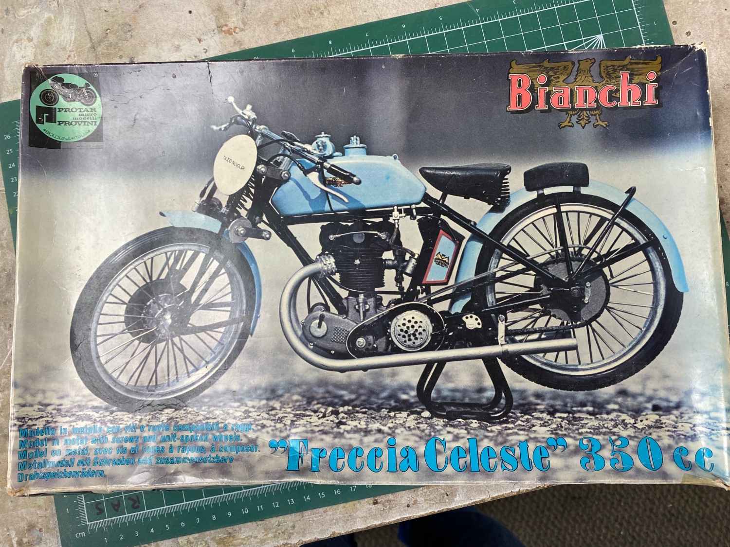
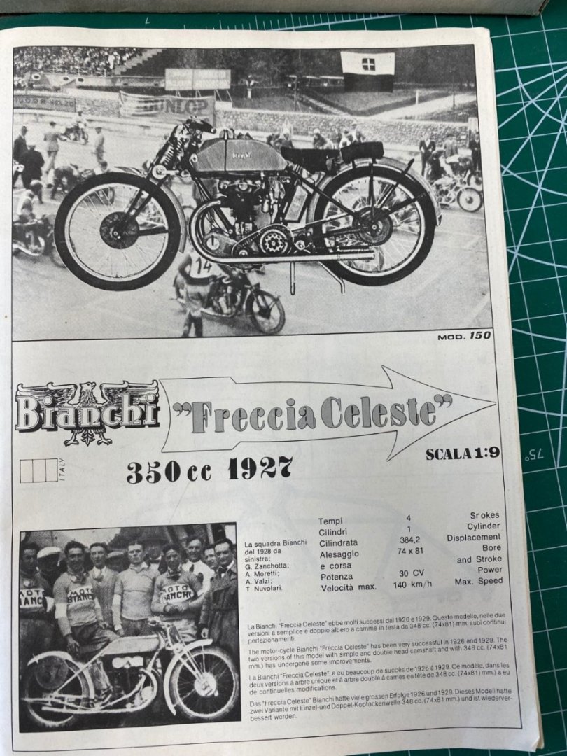
My new project: I purchased a similar kit in the mid 90’s while I was on an assignment in The Netherlands. I started the assembly there and completed the spoke wheels. When I got back to the states the kit was set apart unfinished. Then in 2017 we moved to my current “Senior Living Facility” and, during the move, I disposed of most of my tools and all the miscellaneous kits that I had collected, including this Protar. Once I settled in my new home, I decided to go back to building models. Started with ship's models and, to date, have completed three that are posted in this forum. One day, while browsing on eBay, I found the same motorcycle kit for sale in the UK and, even so the price was almost four times what I paid before for the original, I bought it. Now that I completed my third ship model, I feel it is time to assemble this beautiful model. The history of this motorcycle is described in the following excerpts from the kit’s seller: Quote The Freccia Celeste, named for its sky-blue paint job, encapsulated the finest racing technology of the 1925 to 1930 period. In 1924, to compete with Moto Guzzi and Garelli racing machines, the chief designer Mario Baldi developed a 350-cc single-cylinder engine named "Freccia Celeste", which would grace the most successful racing motorcycles in the next five years. Baldi's design had several original features: the vertical single-cylinder 348 cc (74 x 81mm) engine had bevel-driven double overhead camshafts. Both the camshafts and the valve springs were hermetically enclosed, something unusual at that time. 90° valves were driven directly by the cams, the crankshaft had internal flywheels and the three-speed gearbox was mounted semi-block with the crankcase. Initially the engine developed 24 HP at 5000 rpm and with a compression ratio of 5.5 to 1 exceeded 140 km/h. The team's riders, including the famed Tazio Nuvolari, scored almost one hundred victories in the 1920s winning the Italian Championship in 1926, 1928 and 1929 and five Nations Grand Prix consecutively won at Monza (1925-29). In 1925 Nuvolari set speed records at Monza for the 300 km at 125 km/h and for the 400 km at 121 km/h. Not only on the tracks was the marque successful; the six victories at the Circuito de Lario between 1925 and 1930 and the Tour de Italia in 1926 proved that the "Freccia Celeste" was both fast and reliable. End of quote To date I have partially assembled the frame and parts of the engine. This is a complex assembly. The kit has metal, plastic, chrome and rubber parts. The instructions are beautifully presented. I am looking forward to this new challenge.

- 126 replies
-
- 21
-
-
-
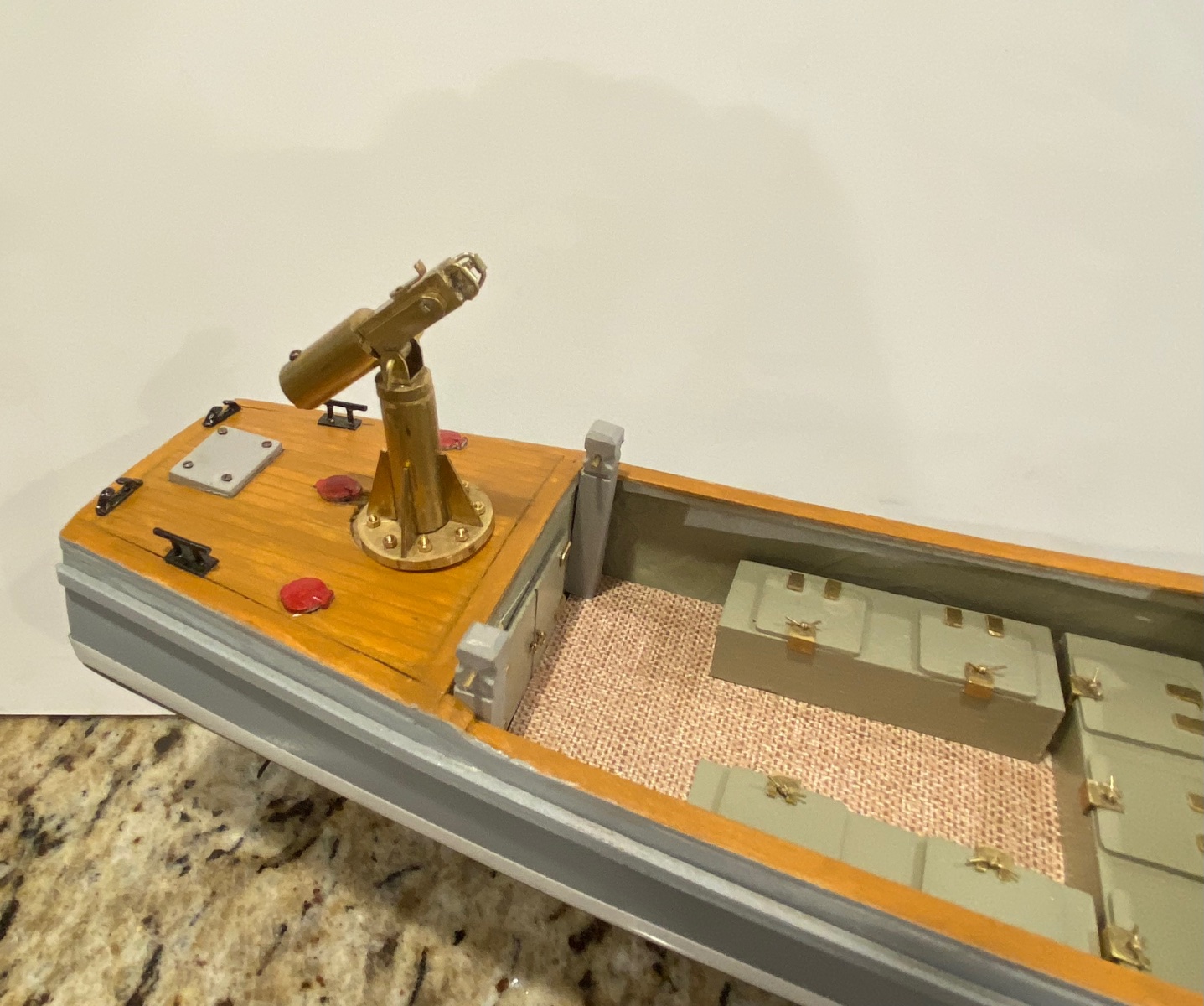
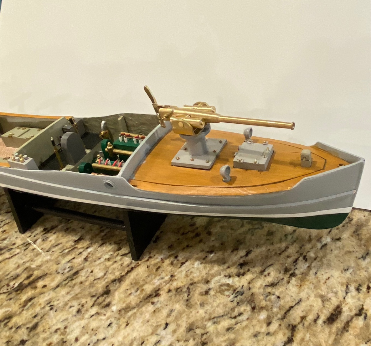
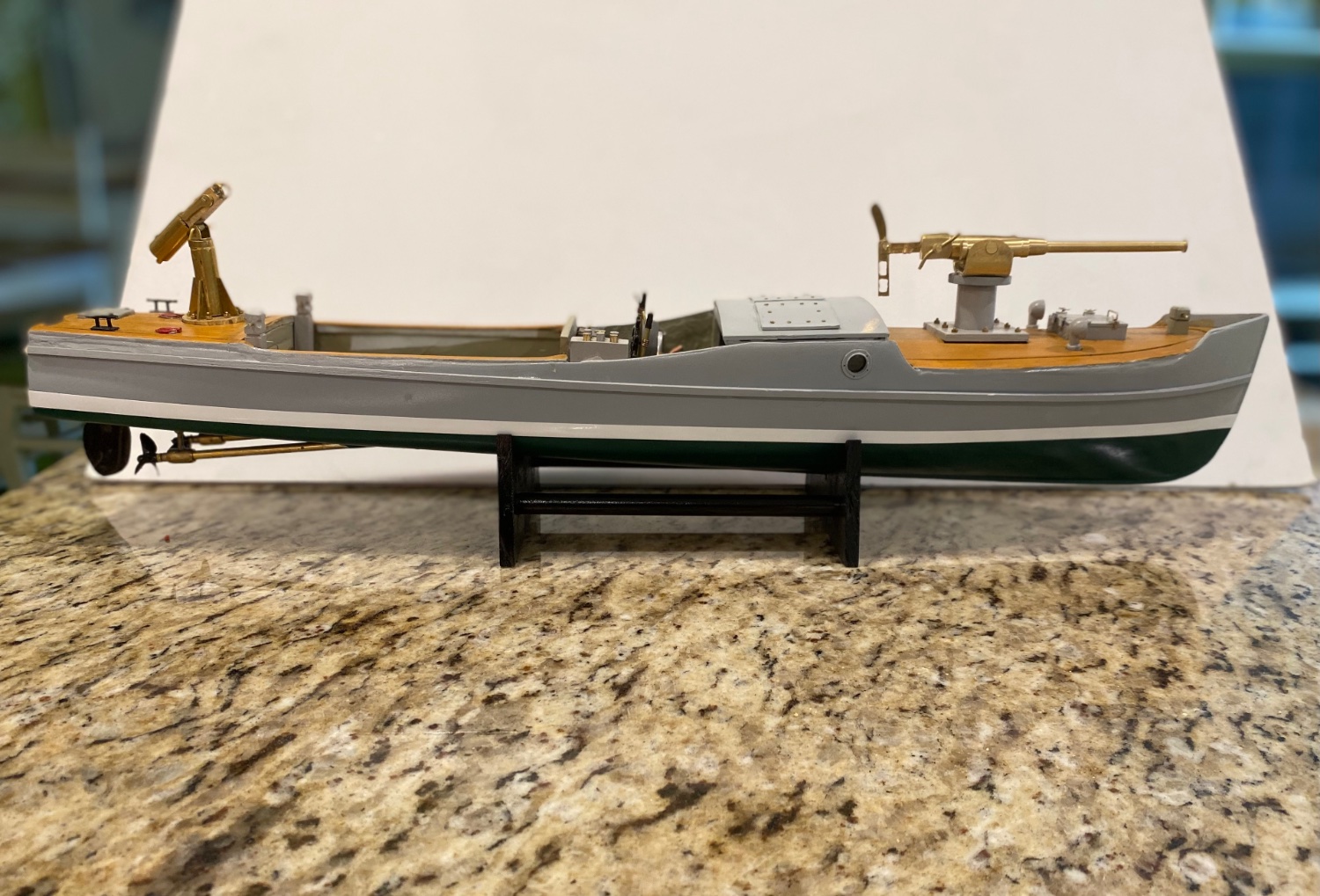
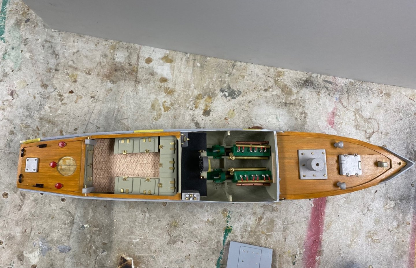
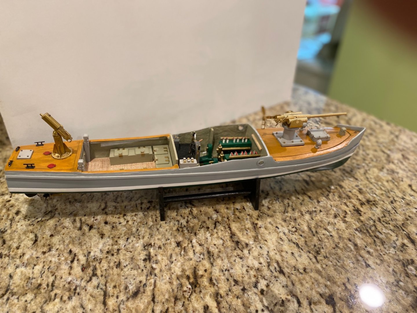
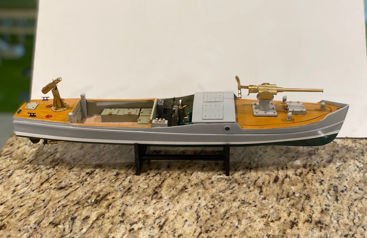
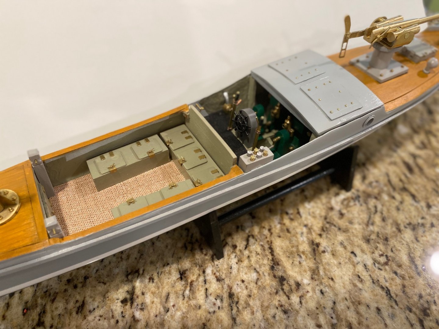
Thanks all for likes and comments. To Keith and Francis : I knew someone will ask about those sponsons on each side of the QF gun. They do show in the plans and were obviously in the design of the boat as the gun was expected to be trained about 120 degrees. The 3 pounder had a very powerful recoil. When they tested the side firing, the gunner was thrown overboard and the boat listed as far as the gunnels. The two victories, the capture of the Kingani and the sinking of the Heissman, were done on the chase by firing only forward and using their faster speed to overrun the enemy. The picture that Francis posted shows the gun trained sideways but, they are not firing it. These extensions were included in the kit from Deans Marine but I decided not to use them. Other interesting point about this gun is that the mount was shorter that normal and the gunner had to squat to fire. If you look at the side view of the model you will notice how big the gun is in comparison with the boat and the higher mount would have made the CG too high, increasing the rolling rate. Anyway, this is what is so good about this forum; how we can exchange our information. I recommend the the book “Mimi and Toutou’s Big Adventure" By Giles Foden. I got mine at Amazon. Again, thanks
-
Thanks Chris. I have not forgotten the card model (V108) thatI am going to make someday.
-
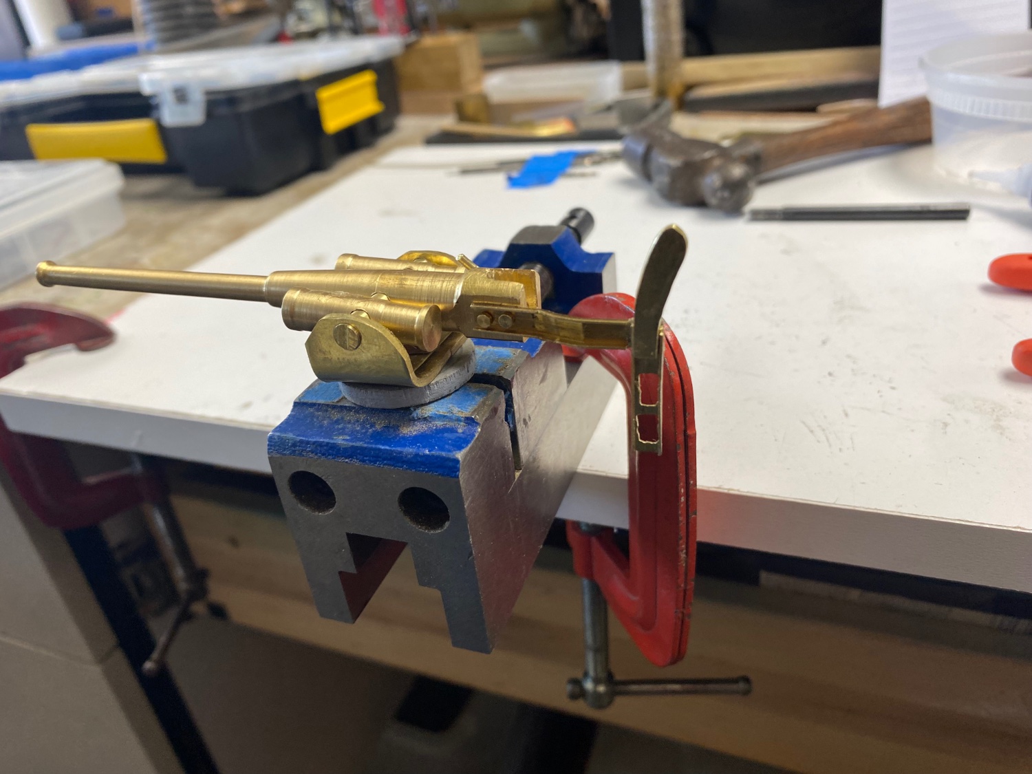
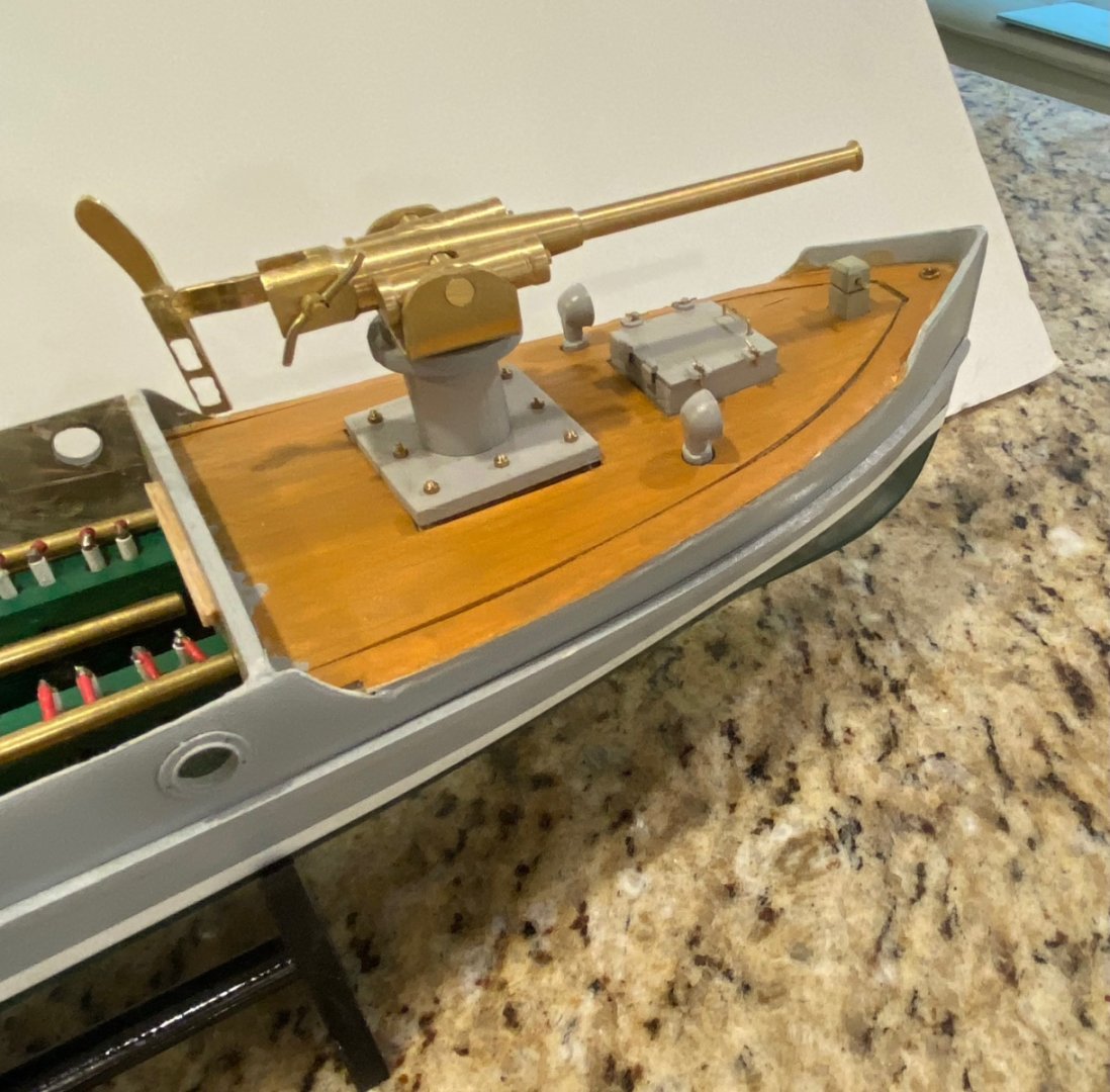
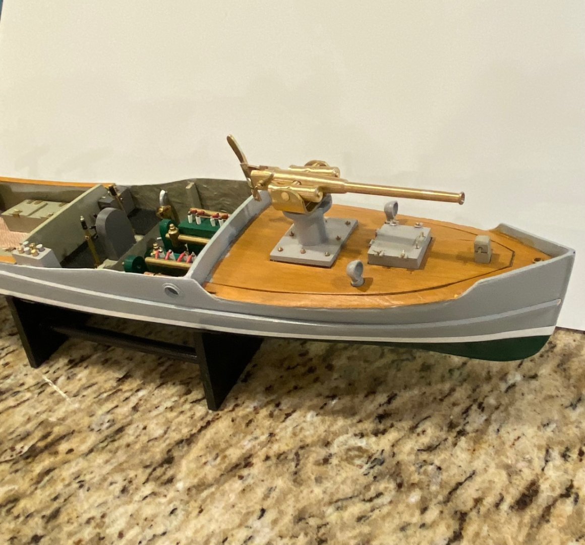
The final touches. Following is the breech opening lever. Then the shoulder rest. I fabricated the channel section by sanding out one side of a brass square tube. Then the gun assembly. And the build is done. The following pictures are show the finished product: FINISHED. My next project is assembling a Protar kit in 1:9 scale of a Bianchi 1927 350cc racing motorcycle named the Freccia Celeste. This bike was driven by five times winner Tazio Nuvolari. The kit has a great history than my be followed in my build log at the Short Leave forum. I want to thank all of you for your comments and likes that made this build possible.


-
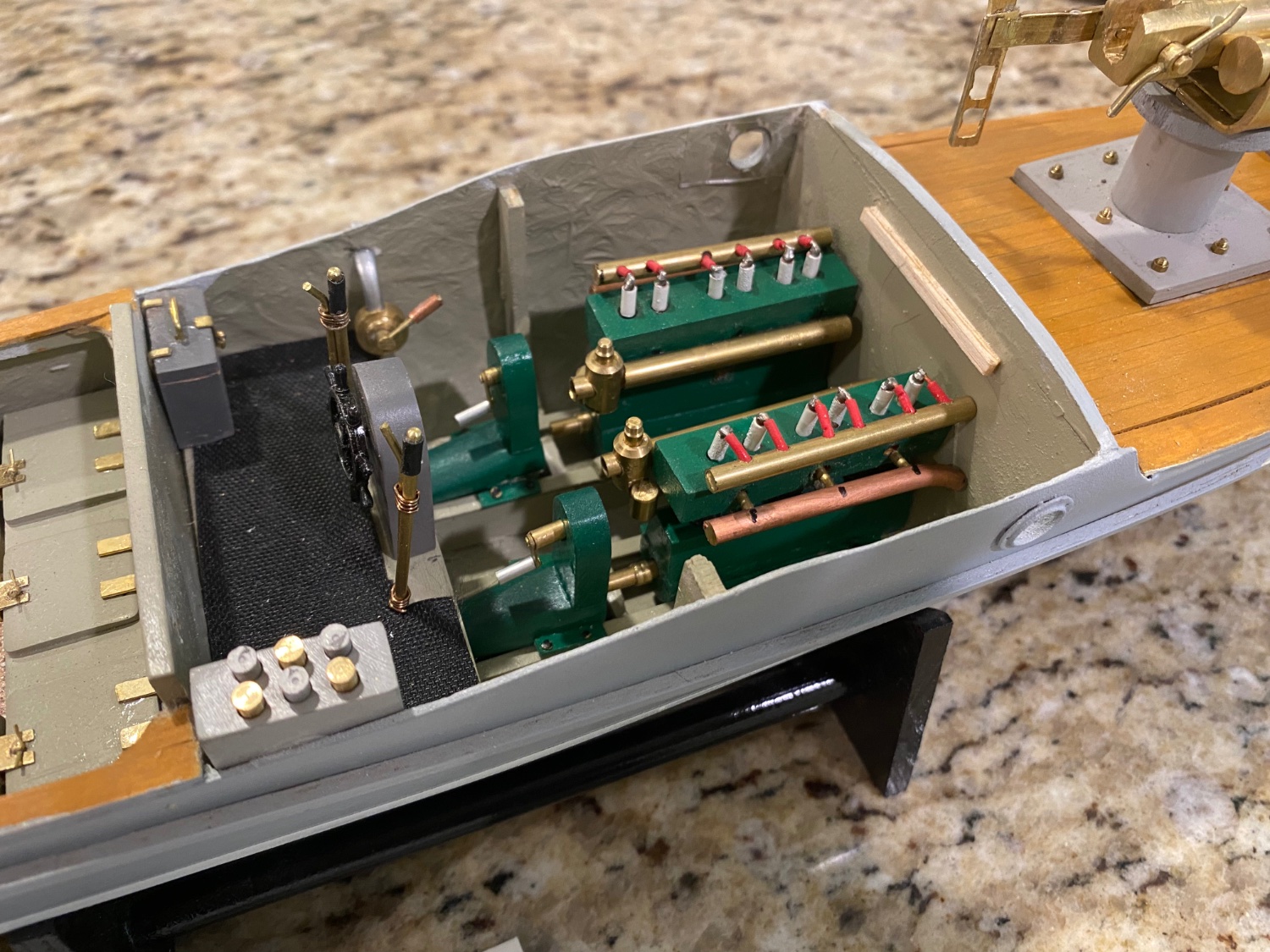
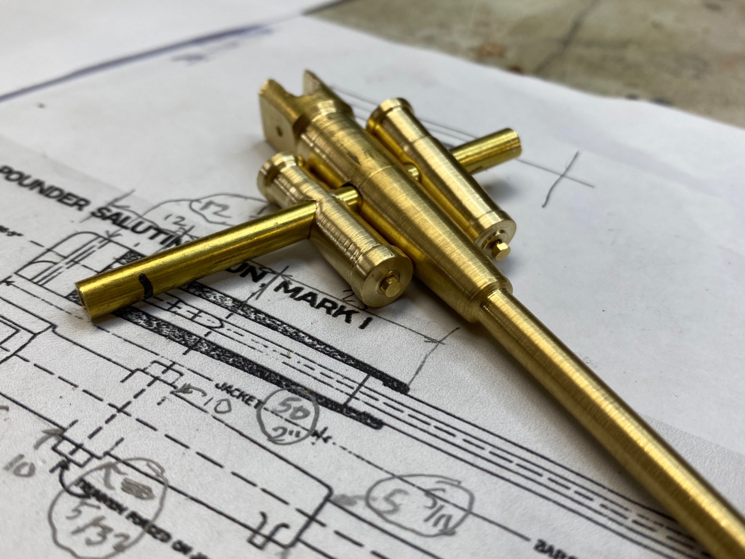
The QF gun progresses and I managed to mill the breech after 60 years since I had used a milling machine. A little touch up with a file will finish it good. The trunnion holes were drilled and the pieces for the recoil cylinders were attached. Mind you that this gun has a really complicated recoil system and I will only be showing a simile. This happens to be my favorite artillery item and one day I may attempt to make a larger scale with more details. The barrel sleeve and the recoil cylinders are joined together on a cradle and the whole assembly is lowered into the the carriage and secured from the top. I decided that was a little too much detail so I drilled the hole through. Today I shaped the carriage and attached it to the base which, in turn, will be attached to the mount already on board. Very little is left for completion and by the end of the week HMS Mimi will be finished. And, again, I repeat myself by stating that I could have not done this without you support, inspiration and sharing of the experience.