HOLIDAY DONATION DRIVE - SUPPORT MSW - DO YOUR PART TO KEEP THIS GREAT FORUM GOING! (Only 36 donations so far out of 49,000 members - C'mon guys!)
×


Keith S
-
Posts
339 -
Joined
-
Last visited
Content Type
Profiles
Forums
Gallery
Events
Everything posted by Keith S
-
Ships vs Boats
Keith S replied to Mike from Aus's topic in Using the MSW forum - **NO MODELING CONTENT IN THIS SUB-FORUM**
I'm going to go with your definition. It doesn't make perfect sense, but it makes more sense than anything else. -
Ships vs Boats
Keith S replied to Mike from Aus's topic in Using the MSW forum - **NO MODELING CONTENT IN THIS SUB-FORUM**
But wait! There's more! An airboat doesn't go in the air. An airship does. There are no rules! -
Ships vs Boats
Keith S replied to Mike from Aus's topic in Using the MSW forum - **NO MODELING CONTENT IN THIS SUB-FORUM**
Ha ha, yeah. Definitely a "sea lawyer". 😁 -
Ships vs Boats
Keith S replied to Mike from Aus's topic in Using the MSW forum - **NO MODELING CONTENT IN THIS SUB-FORUM**
Well, when a ship behaves well in a seaway, sailors say she's a "good seaboat". I submit the two things are largely synonymous, with the distinction being merely a matter of convention. Of course, an aeroplane or even a spacecraft can be a "ship", and a "liner", but never a "boat", unless the aeroplane in question has a hull: then it's a flying boat, but only if it has one hull, never two. And a helicopter can never be a "flying boat", even if it has a boat hull, like a Sikorski Sea-King. But it can still be a "ship" or even a "liner" if it flies scheduled routes. Gunboats are "boats", even the biggest kind, with commissioned officers on a bridge, and a wardroom and accommodations and a galley and the whole nine yards. Again, an aeroplane or helicopter can be a "gun ship" but never a "gun boat"; it's only the boat one that can be called a "boat"... but only if it's not a FLYING boat. Then it's a "Gun ship". I suppose if you took the guns off a large gun boat, it would be a small ship. I mean, what else would you call it? Of course, you can call a small steam-powered ship a "steamboat", but if you change the steam engine for a diesel, then it's a "ship", not usually a "diesel boat", unless it's a submarine or a tug. Or one of those colossal ships that sail in the Great Lakes: those are obviously "boats" whether they're steam or diesel or whatever. As for seagoing ones, you can have "steam ships" but if they're diesel powered they are suddenly called a "motor vessel" even though they all have engines, not motors. Which brings me to the subject of the difference between engines and motors....- 28 replies
-
- 10
-

-

-
Well, using dates is problematic to say the least. These ships must be regarded as sort of the NASA "super guppy". This aeroplane started life as a bog-standard Boeing Stratocruiser, and ended up being a weirdo unpressurized turboprop heavy carrier with only the pilot's control-stick being original Boeing standard kit. Here's the thing about Erebus and Terror. They recently raised the Erebus's bell. It says "1845" on it. We all know that Erebus was built well before 1845. We all also know that sailor-folk consider all that is "the ship" resides in her bell. My point therefore is that if they gave them new bells before their last voyage, it's likely that everything else was updated as well. That's my thinking on the subject, and I invite polite debate.
-
I just want to caution you now: When the Greenwich museum asks you to donate your model, you should be aware that you'll probably never see it again without paying. I've seen ones in there that are hundreds of years old. Those guys never got their models back either.
-
Do you mean to say you'd add 3mm so the lubber's hole could be made bigger? So the main topmast stays could fit down through the foretop? Yes this ship seems to have been covered in boats, like turtles on a log.

-
Oo, I like the little sheaves in your kingposts. Mine are just simulated with a little circle of wire. I also like the bell- yours looks more like a real one than the one from the kit. Where'd you get that? Also I see you got some rope onto the ends of those guards. Maybe I gave up too early. I'll have to borrow my wife's reading glasses and get a needle-threader from the sewing kit and try again. 🥵
-
Thanks Keith. I think I'm mostly focussing on these little metal bits because I'll do almost anything to put off getting started on the masts and tops. Lee's book is making my head ache. Plus, I'm waiting for some walnut and basswood planks to arrive before getting started on them. I think I have a plan for the tops based on Lee's but will wait till the timber arrives before trying it out. I'll just use your dimensions for them if you don't mind!
-
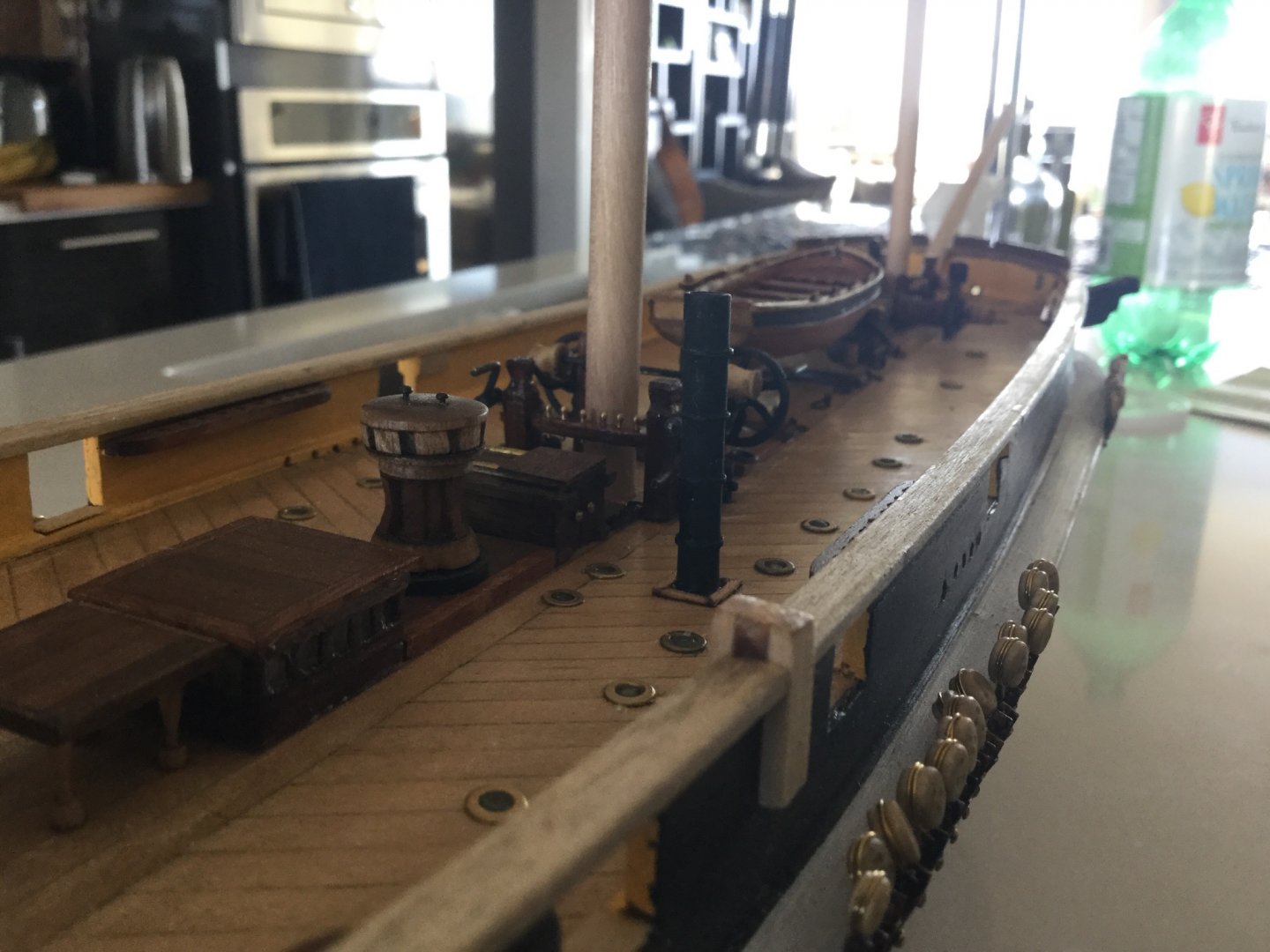
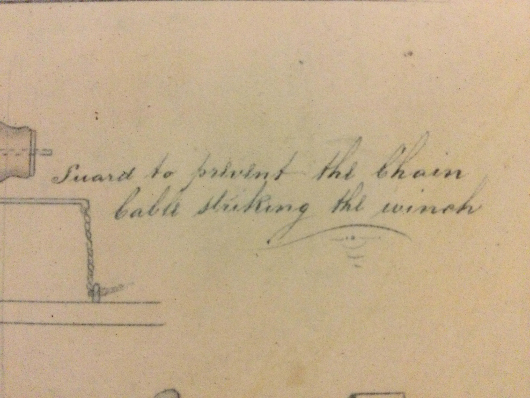
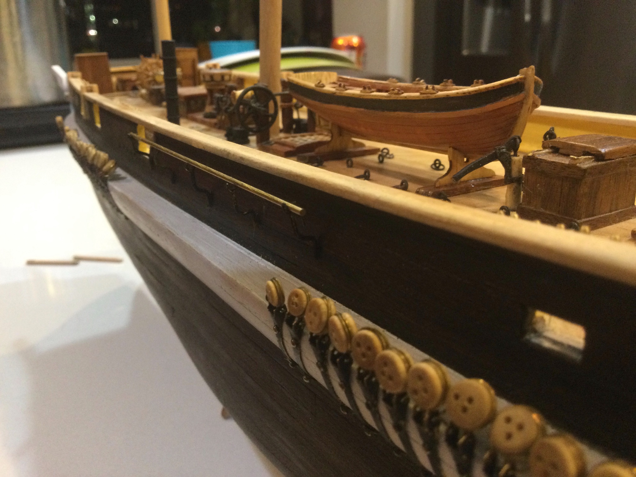
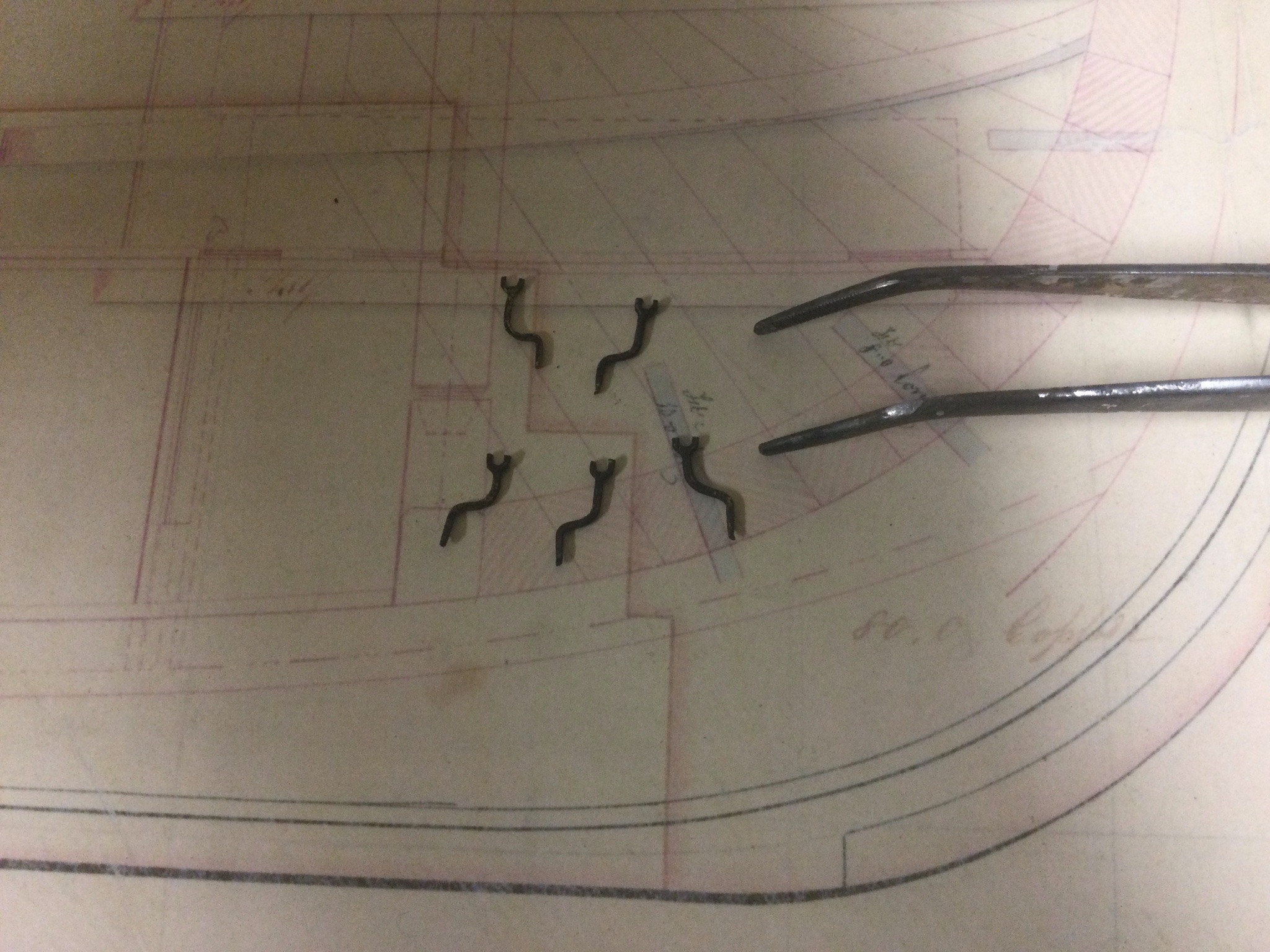
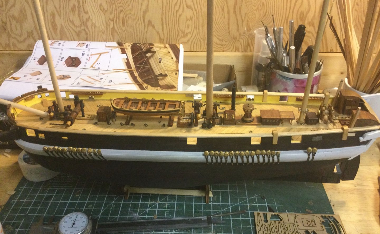
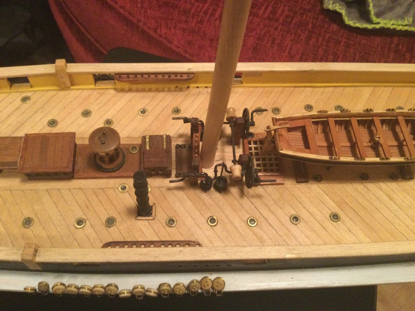
pToday I fixed the other half of the fife-rail on the foremast, to hold the correct number and size of belaying pins. Also, continuing with the micro-blacksmithing, I made the thingies that are described in the plans as "guards to prevent the chain cable striking the winch" I actually managed to drill little holes in the ends to tie off the cord depicted in the plans, but it's so small I found it too fiddly to attach the cord. But I did make the rings, in case I decide to try again. Maybe I will buy some reading- glasses. I hate taking these close-ups. I don't feel like my work is equal to the nice, crisp work of the other guys who are building this ship. I swear, from a foot back it looks pretty good. Oh well

-
I should point out that that note in the full-sized plans only seems to refer to the davits between the fore and main masts. I have no idea if it's true for all of them. Drawings of the ship depict boats hanging from the sternmost davits while under weigh. I don't know how this would have interfered with the travel of the spanker-boom, however I've been doing some reading about sail-handling and it seems likely that unlike a schooner the fore-and aft sails would have been brailed up on a run before the wind, so likely they never let the spanker boom out that far in the first place. This is just a supposition however. What do I know. Ha ha.
-
The math checks out. But man! That's a lot of boats! As well as all the barrels stored on deck, and the frames holding spare spars and other wood, how did they even move around? It would be fun to try to depict the ship burdened with all this deck cargo, but I'm worried some of the detail we've already done will be buried in a solid coating of boats!
-
I like 'em too, but man that's a lot of boats. I think I have six of them, including the two small double-ended metal ones, which I figure are OK to put upside-down on the beams between the main and mizzen mast. With two piled up in the middle, one one either side on the stern davits, and two upside-down, well I guess I could put one more in the pile in the centre, and hang one off the transom, and that would make eight. I wonder where they put the other four? I suppose the really little ones could be partially disassembled and stored below. I've heard of small boats being stored inside big ships and used for storage...
-
I agree, I'm going to attach the arms on the outside of the bulwarks. As for the forward midship pair, the note on the dockyard plans does say that they are normally removed and stowed- so I think that solves the problem nicely. As for whether the midship davit posts were inside or outside, after I put the little fender hardware on there, I can see that there is lots of room for an outside davit. Perhaps these ones were located outboard because of the spar storage inboard. At any rate I think I'll attach the metal hardware but leave the posts off, because of that note in the plans. Do the aft-most davit posts block the driver boom? All the drawings of the ship under weigh show a pair of boats hung from davits near the stern- I suppose those must be the ones by the skids.
-
I had a hard time making the holes square. Yours looks pretty good. On a separate note, I notice you've lined all the apertures in the bulwarks with thin wood. That must have taken hours, but it looks really shipshape. I wish I'd done that.
-
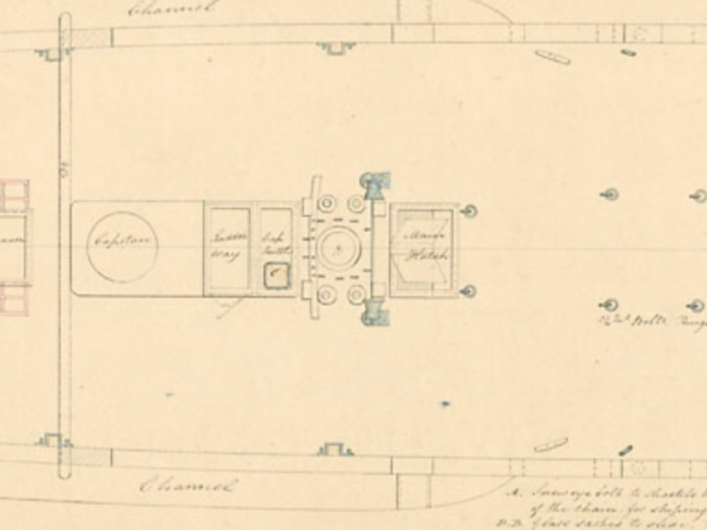
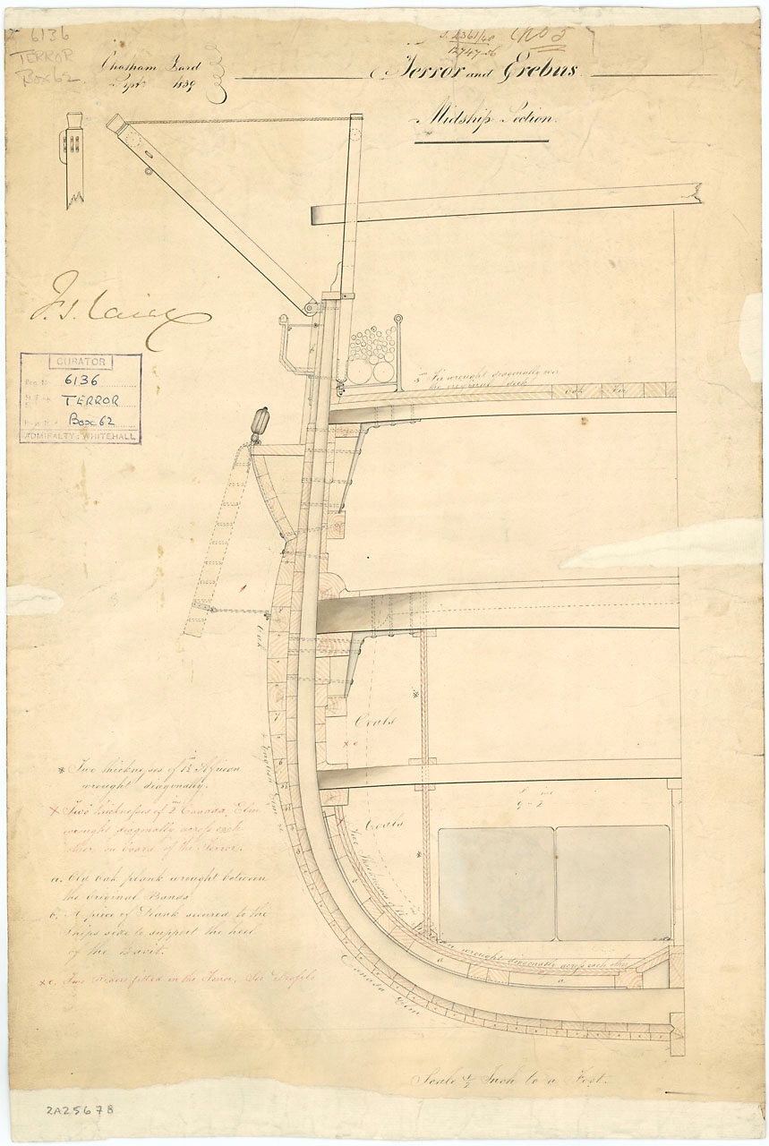
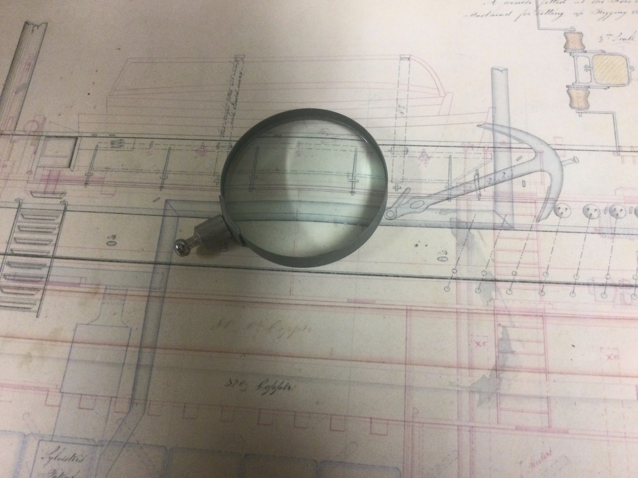
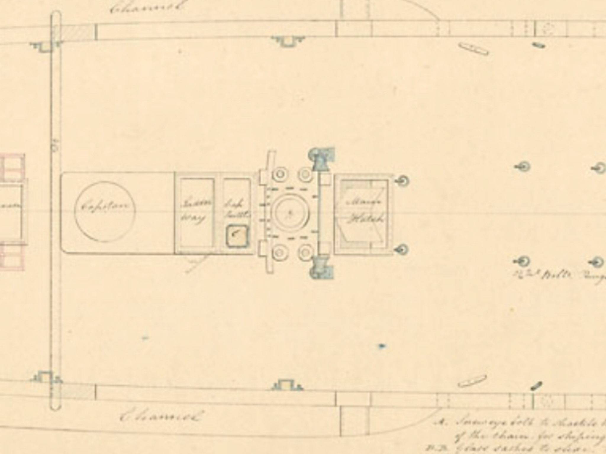
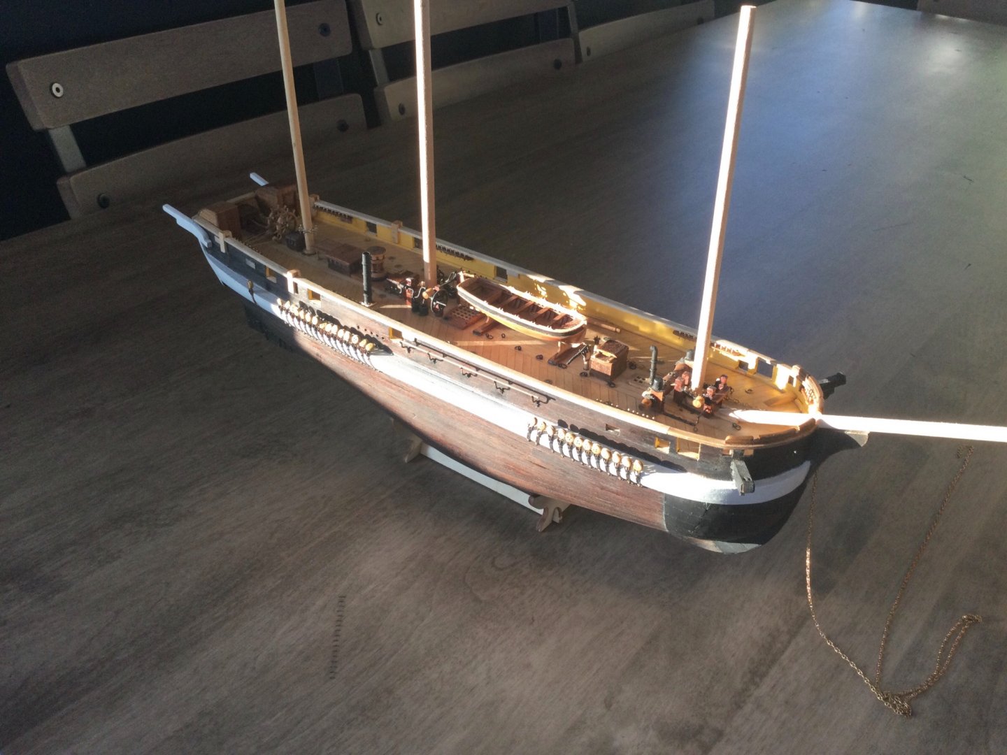
OK guys, I hate to boast, but I am quite pleased with myself for once after this evening's building session. As I mentioned in the post above, I have been a bit confused about a series of brackets depicted in the various dockyard drawings. They seem to serve no apparent purpose. I decided to build a set and glue them on anyway, thinking that perhaps in the future their purpose would become apparent. I glued them onto the side of the ship (I will secure them with little brackets later) and still couldn't work out what they were for. Then on a whim I decided to lay a piece of rod in them, which seems to be depicted in the cutaway diagram above. I suddenly realized what they are for. All the other boat davits on the ship hang outboard of the shrouds. Therefore, if the ship were rolling, the boats would bump harmlessly against the shrouds. In the ship's waist, however, a boat hanging from the falls would bash against the ship's rail... unless there was a fender of some kind. I believe these brackets form a fender that protects boats from bashing into the ship.


-
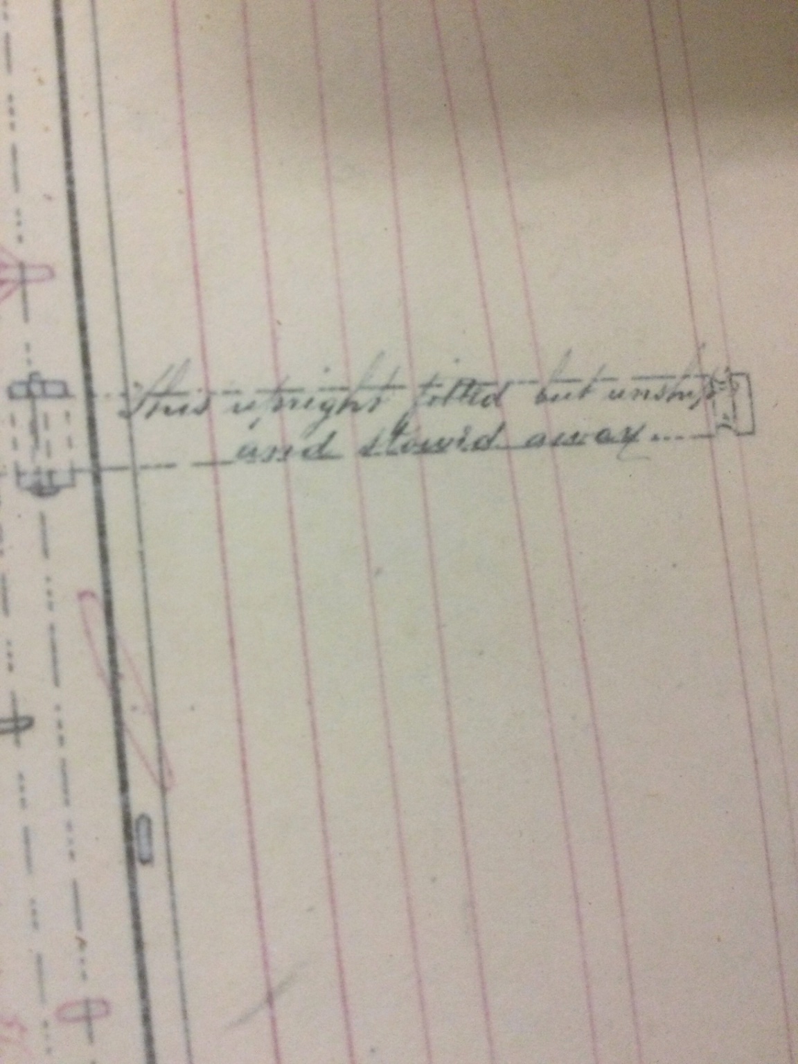
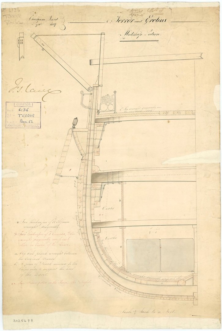
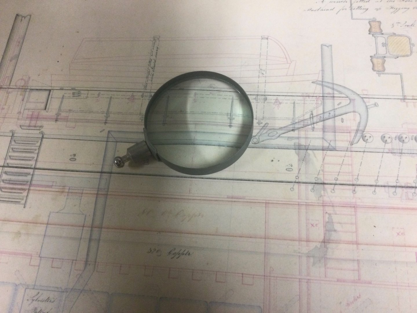
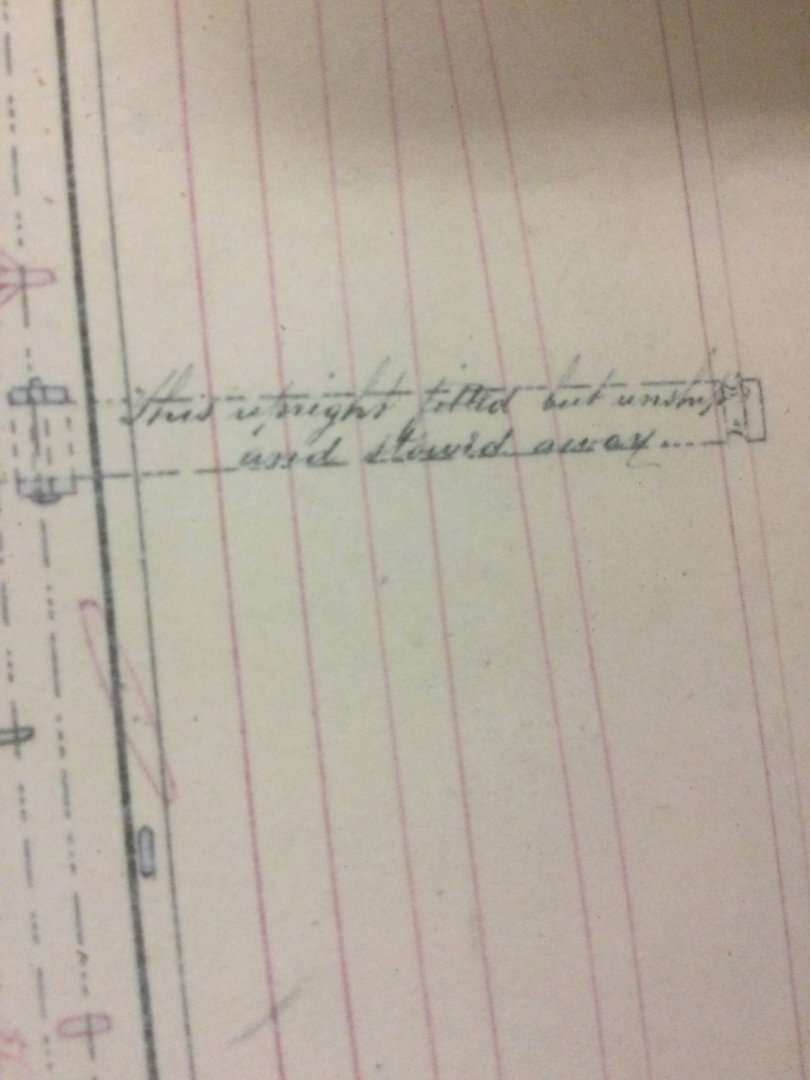
One of the things I needed to do was to break off all my belaying-pin racks and replace them with ones that fit the scale 5mm pins. Now they are all the correct size, except, I just noticed, the ones on the port side of the foremast. These ones will be sorted by plugging and re-drilling the holes rather than breaking apart that complicated structure. Also I made two new ones for either side of the bowsprit, having seen these depicted in the dockyard plans. I've made a start on the life-boat davits, having made two of the ones closest to the stern. This however has lead me to a bit of an impasse with respect to the two midships ones, that are depicted in many drawings as being mounted OUTSIDE the bulwarks rather than inboard. I have this dockyard drawing of a midships cut-away of the ship from 1838 that depicts an inboard-mounted one, but with the davit arm being mounted outboard. However, it also depicts the racks for carrying spare spars, which are only mounted where these two davits would have been. Also depicted are some strange little irons or brackets OUTSIDE the bulwarks. I can't work out what these are for, but in the side-view from the same era, we see five structures depicted. At first, I thought these were simply the stanchions from the inboard racks. However, after measuring them, I see their locations do not match up with the inboard stanchions. Furthermore, they are exactly the same size as the weird little brackets depicted in the cross-section. Therefore, I made some up out of brass. They are the correct size and shape, but I simply can not work out what they are for. Anyway, I made some of these little brackets. I am experiencing confusion about them, however. IF, as seems to be the case from the 1838 plans, these brackets were located along the waist of the ship, and IF, as also seems to be the case, the midships davits were installed OUTSIDE the bulwarks, they would appear to interfere with one another. The davits depicted in the cutaway are either not the midships ones, or there is a discrepancy in the plans somewhere. In the side-view, the davits are depicted in blue ink. The convention on this sheet seems to be that things inside the rails are in red, while those outside are in blue. So I'm pretty confused about what all these parts are and how they fit together. There are a few notes, barely legible. On the cutaway there is a faint "b" drawn beside the davit, and the note, in 19-century cursive, seems to say "a piece of plank secured to the ship's side to support the heel of the davit". This seems to refer to a vertical plank under where the horizontal moving part of the davit is secured to the outer side of the bulwark. The other note I can read refers to the vertical part of the midships davits, saying "This upright fitted but unshipped and stowed away". So, this being the case, I've decided to simply not put these davits on the model. I will instead install the little iron brackets, and the mounting hardware for the davits, but as for the davits themselves, I will not install them. The little irons seem to be meant to support a horizontal railing or spar of some kind, but I will not install that, either. In that way, if I later learn what the heck these things are for, and how ,if at all, they are meant to interact with the davits, I will be able to complete that bit of the model. One thing that remains mysterious to me, is WHICH of the davits are depicted in the cross-section. If they are not the midships ones, then it would seem to indicate that the horizontal sections of all the davits are mounted to the bulwark rather than to the uprights. Another mysterious thing is that, in the side-view, the line representing the bulwark railing is drawn OVER the davit uprights, rather than BEHIND them. This would indicate they are NOT mounted outboard. It's all very mysterious. I will have to think about this rather important point for a while before deciding what to do about it.

-
I love the rails inset into the yellow cedar flooring. That's exactly what I had in mind for my deck, although I will probably never get around to it. The little locomotives are brilliant. I especially like the electric one with the functioning scale motor controls. The "Billy" was very easy to build. The instructions are really good. If you just buy cylinders, Roundhouse will give you their information on valve-gear geometry to help with that part of it. I was thinking of buying a pair to power a model steam-boat:another pipe-dream of mine. The "Billy" built up from three kits: the chassis (including cylinders and valve gear) which bolts together using Roundhouse-supplied BA spanners, plus you need a screwdriver and a needle file to dress the rods a bit. That's about it. The next kit is the steam plant, including boiler, burner, safety-valve, regulator, lubricator, gas tank, pressure gauge, &c. All the silver-soldering is done already, and it comes with test certificate and just goes together using the supplied spanners and screwdriver. The body kit is etched brass, with all the fold lines etched in, and requires a bit of soft-soldering by the builder. I found painting to be the most difficult part. Setting up the valve-gear took a bit of work but the instructions reduce it to a very methodical and logical process.
-
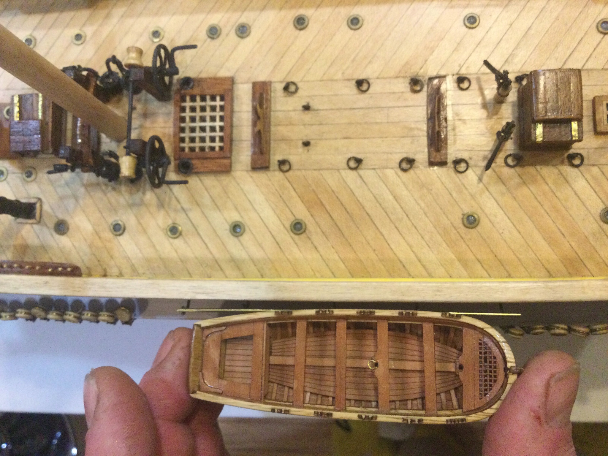
Hey, nice job on the boat! Those little boats are like a ship-building project by themselves. The crazy thing is how many boats these vessels had. TWELVE. I bought a few more "master Korabel" boats which are roughly the right size, plus a "model shipways" one that is a bit larger, to make the bottom one on the "stack" of boats in the waist of the ship. I reckon I'll have three boats piled up midships, two of the double-ended metal ones upside-down on the rack in the stern, and two hanging from davits, and still be about six boats short of a full load! I can't work out where they kept them all!
-
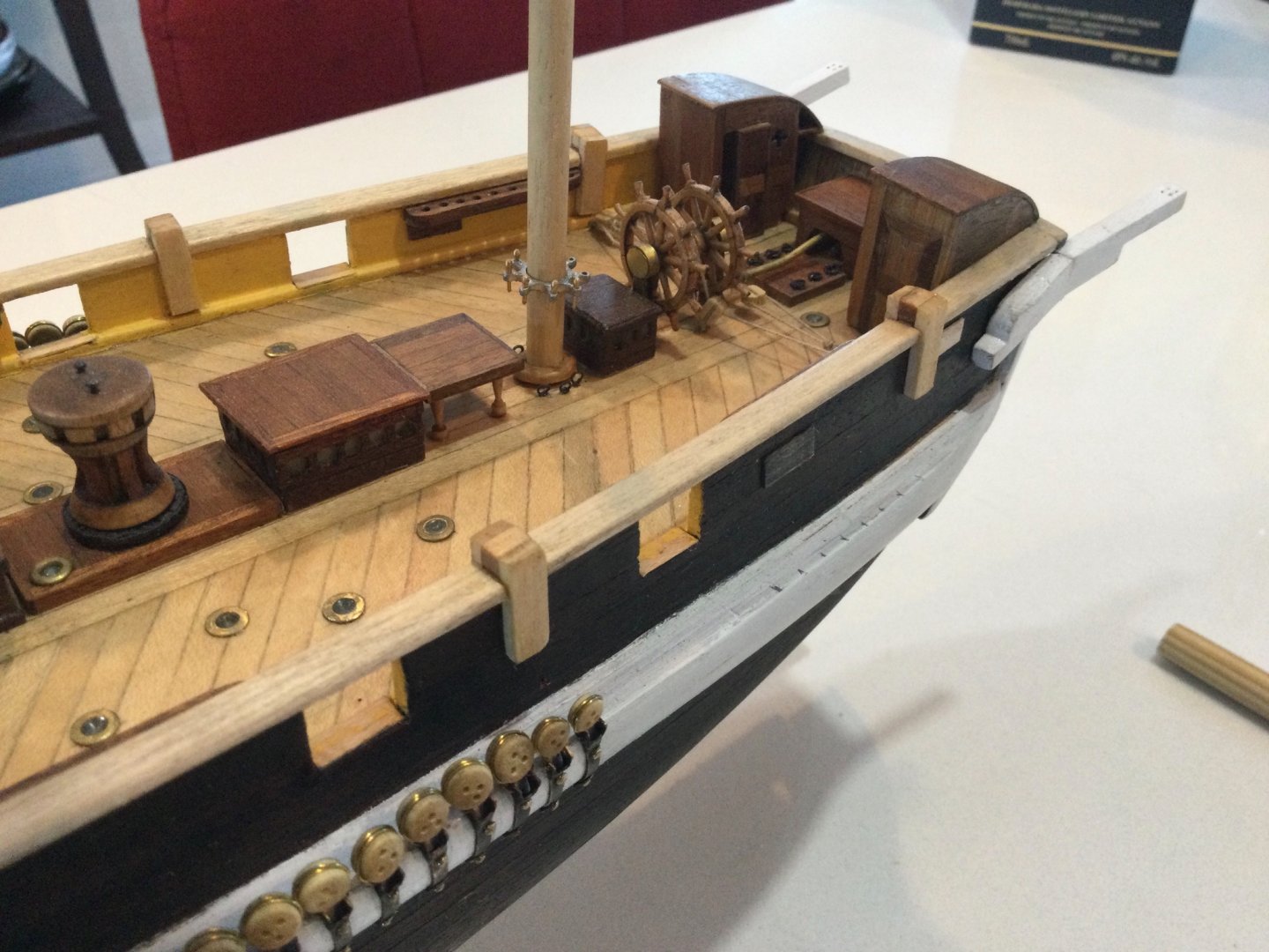
I'm back. After leaving this ship on the shelf since May, I have finally reached the point where I wish to work on it again. I decided to start by building the little hutch over the rudder head. There is quite a bit of detail to this little piece, and it's a funny shape. I am happy to be back at it. Next up I think I'll work on some boat derricks, and I still need to remove the pin-rails and replace them with proper holes for scale-sized pins. I'm also looking forward to beginning work on tapering and fitting out the masts.
-
Keith, are the dimensions of your fighting tops the same as the parts supplied in the kit? Did you use any of the plywood kit parts or are they completely scratch-made? They look great.
-
You're welcome! I made the pump shaft bushings out of little bits of brass tube held on with small brass sheet straps on the front posts, and on the aft ones I just used the eyes called for by the kit but attached to sides rather than the top. You're correct, the aft companionway is cut down, I assumed it was to allow clearance for the capstan bars. I built mine using kit parts, and then ground it down on a sheet of coarse sandpaper before putting the finishing veneer on.
-
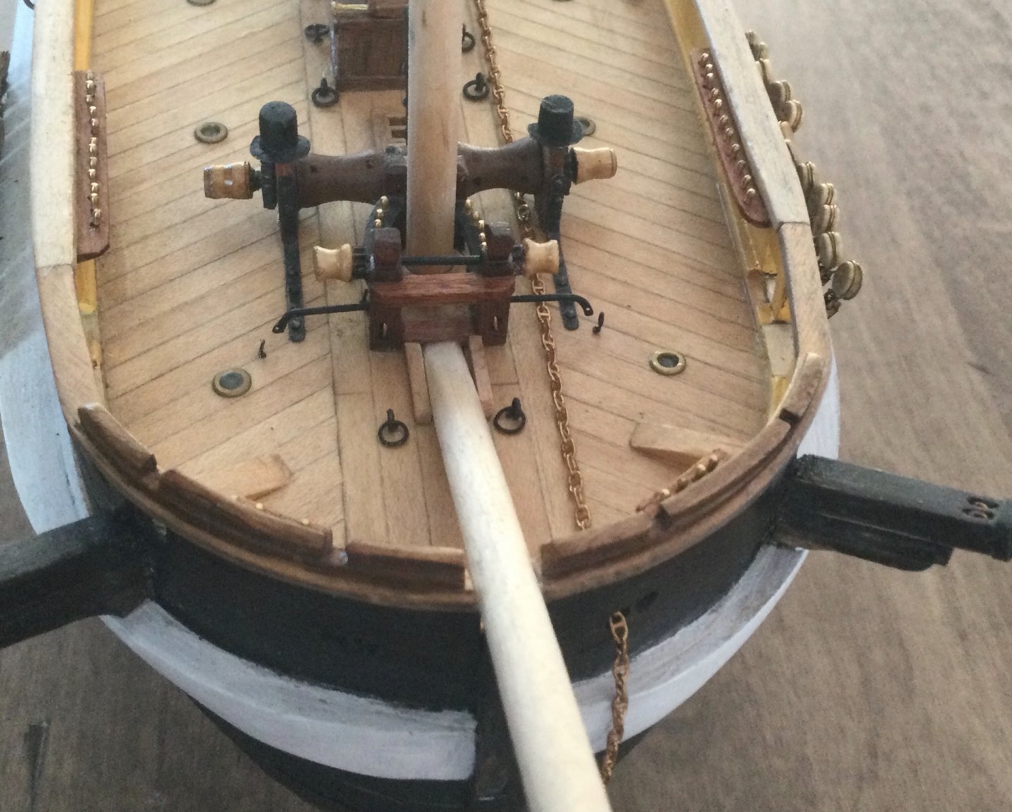
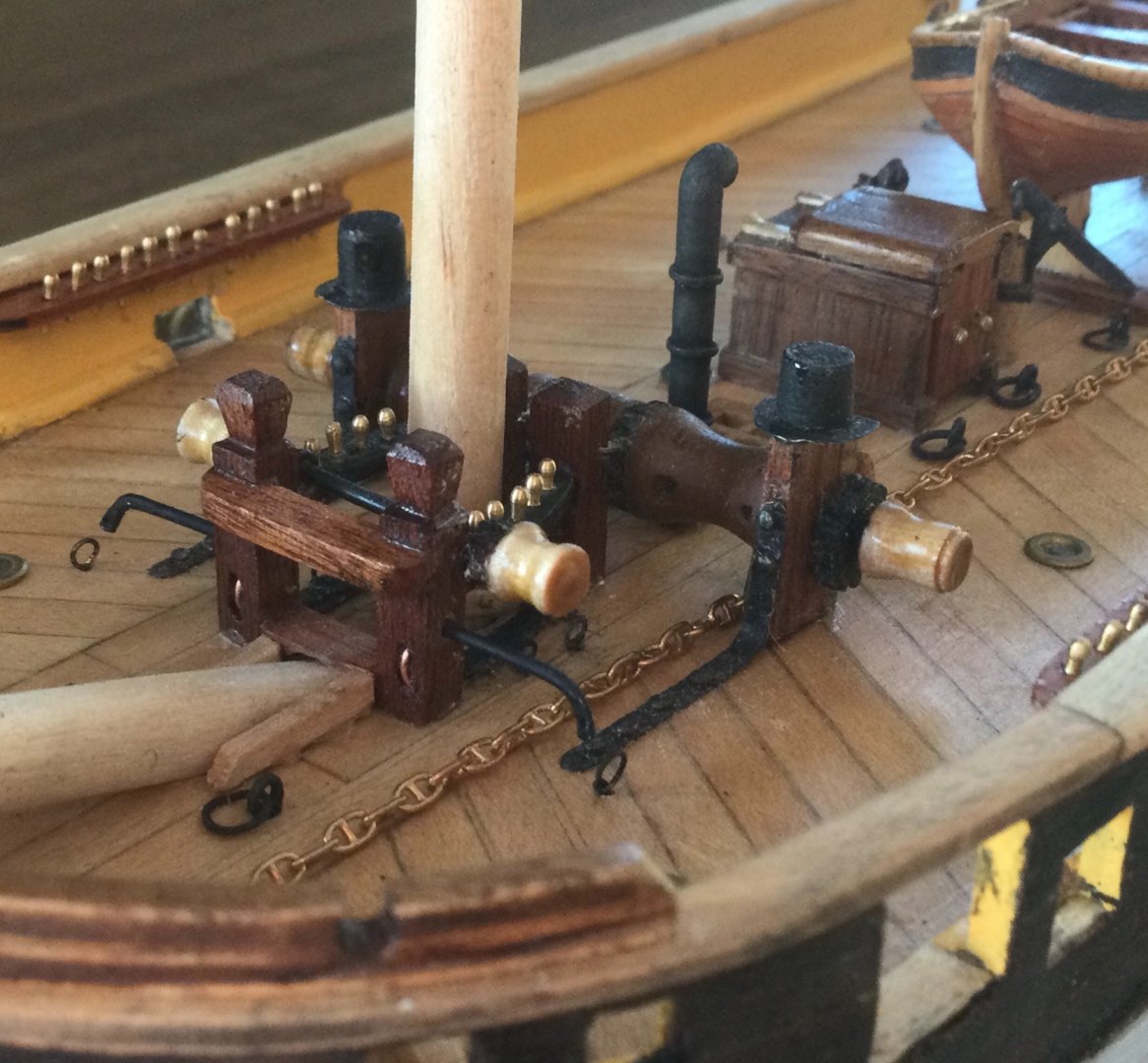
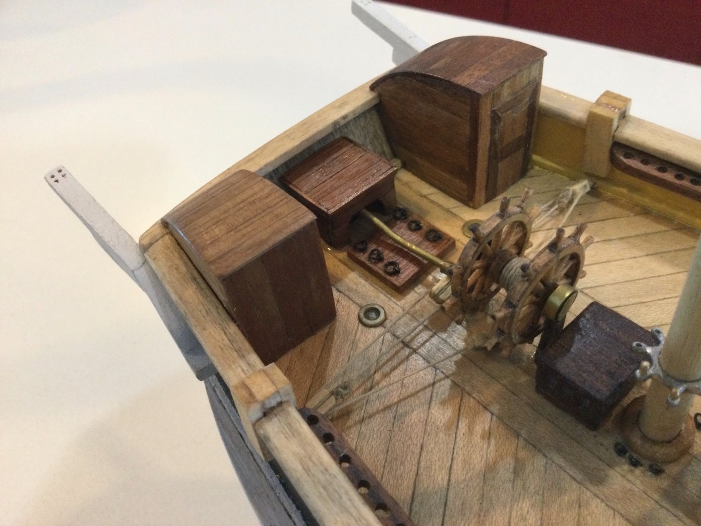
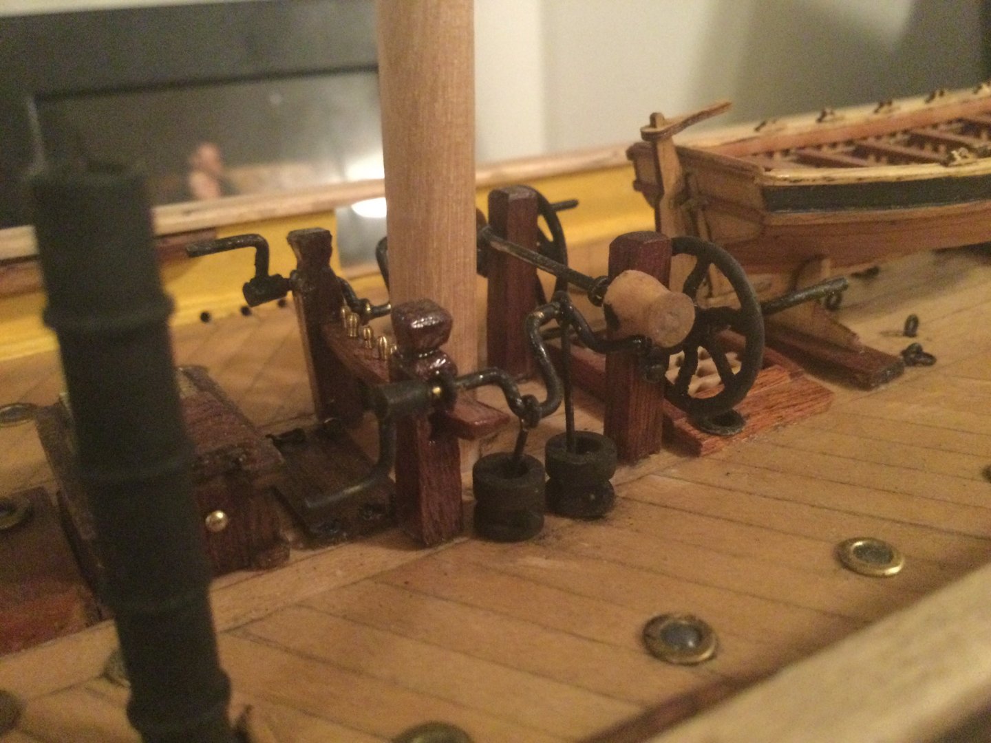
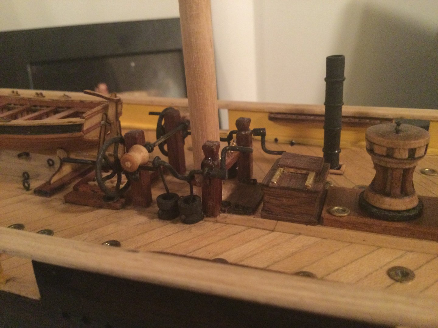
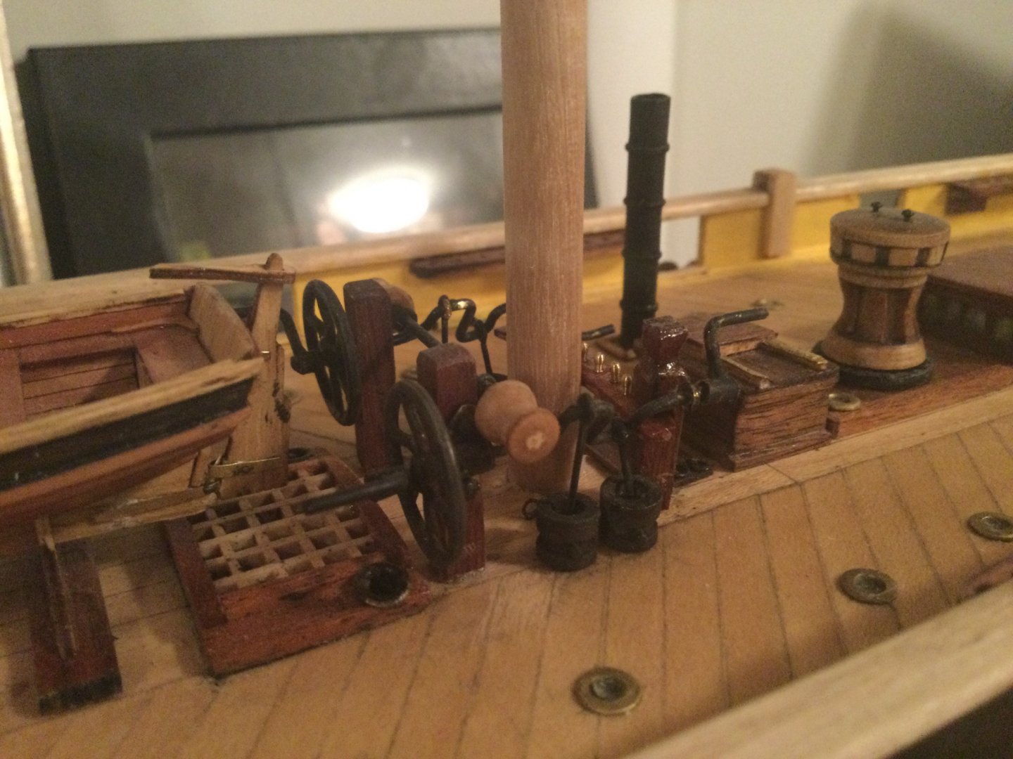
Happy New Year to you as well! Those things, I believe are called warping drums or warping winches. Have you seen on most modern recreational sailboats, there's at least one little hand-cranked winch on either side of the cockpit? It's like a giant one of those. The ones in front of the main mast probably had big removable crank-handles I think. I thought I saw that depicted somewhere in the builder's draughts. There's also a set of them forward of the foremast, and also at the top of the fore and main masts. Although other Keith believes the ones up in the tops would have been removable and only up there during rigging. I'll try to find some information on that stuff for you. It's in the builder's drawings somewhere. Other Keith and I managed to basically make the same thing without really consulting with one another, ha ha. I can't remember if you said you'd managed to get those F-scale brake wheels from Ozark miniatures. Here are some pictures of my model of this area on the ship. Sorry to put pictures of my model on your build thread. I hate taking pictures of the model this close up; I swear it looks perfect from two feet away, but in these closeups I can see all the slopped paint, fingerprints, blobs of glue and crappy carpentry. Anyway this is what the contraption looks like. Note the four vertical posts are taller than the kit ones, and the aft pair are "kingposts" which mean they have that top bit to tie lines off upon. I used the pump heads from the kit, although they are not quite correct, I decided to pick my battles ha ha. I can measure this stuff up tomorrow if this helps. I'm pretty sure I got it more or less right. EDIT: there is a good diagram of this area on Matthew Betts' blog entitled "getting pumped for Terror's birthday" Note the aft posts are also angled slightly backwards a degree or two. I didn't get this right on my model. Didn't notice till it was too late!
-
Hi Daniel, I think those are going to work just fine. They are certainly nicer than the ones I got. Some of mine were poorly machined and look more like dressmaker's pins than belaying pins. Where did you get those ones? Also if I may make a suggestion: if it's not too late, that particular fife-rail (the board the pins are stuck into) was curved on the original ship. You may find the larger, correctly-sized mast is a tight fit otherwise. This is one of the things the kit gets wrong. If it's not too much hassle, you might want to re-do that. I'll try to find a picture of mine.