HOLIDAY DONATION DRIVE - SUPPORT MSW - DO YOUR PART TO KEEP THIS GREAT FORUM GOING! (Only 36 donations so far out of 49,000 members - C'mon guys!)
×


Keith S
-
Posts
339 -
Joined
-
Last visited
Content Type
Profiles
Forums
Gallery
Events
Everything posted by Keith S
-
This is one reason I'm glad we bought those studded chains for the anchors! Now I can use the kit-supplied chain for futtock shrouds.
-
I'm using 5mm belaying pins. They are the correct size according to the full-size plans, but I find them to be so small that some are not machined properly and just look like little pinheads. For pin racks I'm tapering them so they're a bit thicker where they attach and thinner where the pins go through. I think other Keith's 8mm pins are a very good compromise between scale size and reasonable function. After all, we will need to tie lines to them. The 5mm ones are so small they don't look right, even though they are. I would go with 8mm ones if I did it again.
-
That was me! I'm back at it now, sort of. I need to tidy my workbench and then I'll be starting again. Sometimes it takes me a few years to complete a model because I start thinking about it so much it becomes unenjoyable.
-
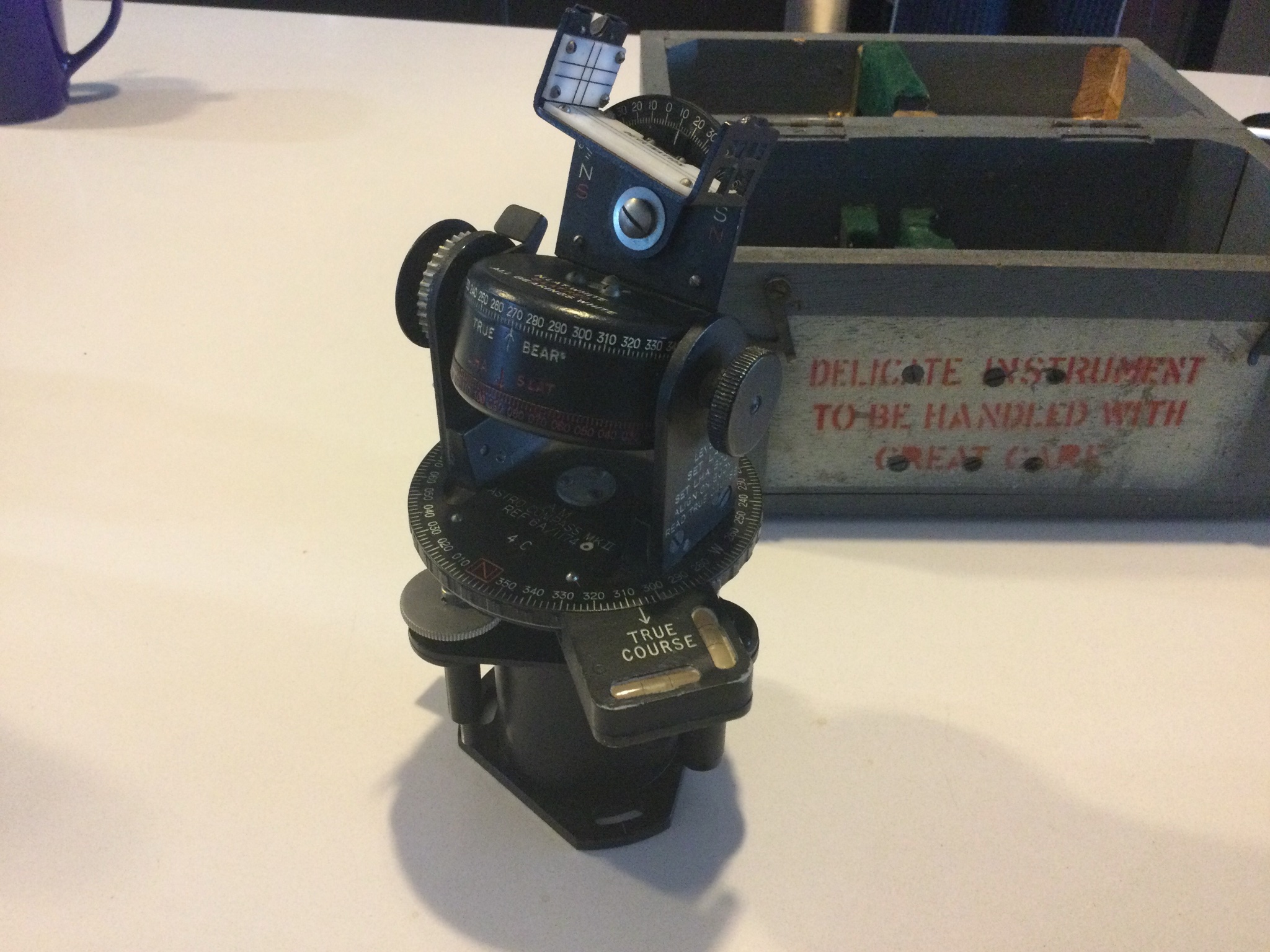
The map on the wee table is a nice detail. Somewhere in either the full-size plans or maybe Michael Palin's book I saw it labelled as an "azimuth compass" table... I imagine an "azimuth compass" may have been the same kind of thing as this "astro compass" that's only about 90 years older. Since compasses don't work in Polar areas, navigators use them to work out their heading using the sun or stars. They're still kicking around where I live because aeroplanes are required by Canadian law to carry a source of heading information that is "independent of a magnetic source". In order to use one, you need to know where you are, what time it is, and the "Greenwich hour angle" of the celestial body you intend to use. Since GPS was invented at the beginning of my career, I have only ever used it to calibrate the new compass on my sailboat. But I keep it around because I think it's interesting.

-
Hello Michael, as a matter of fact I just finished building a large deck in my wasteland of a back garden before the freezing weather arrived. I wanted a real garden, but the ground my house is built on is just manufactured ground made of large boulders filled in with diminishing grades of crushed rock. So I would have had to build up a great deal of soil and retaining walls, etc. I've settled for decking over the whole lot and installing planter-boxes with tops that are flush with the deck. Anyway I now have a level surface for some track, although it will not be a true garden railway and my wife will probably react negatively to permanently installed tracks. I was thinking about using a router to carve flangeways in it but this is probably a pipe-dream. Still, some temporary tracks to have fun now and then might be acceptable. I am familiar with Peter Angus' work. He makes nice-looking locomotives. I have a subscription to "16mm Today" and membership in the garden railway association so I see lots of locomotives. Mine is basically a standard RH "Billy" with the side bunkers removed and a new spectacle-plate added. I've been concentrating on my model of "HMS Terror" lately, but in Springtime will probably set up tracks on the deck and give the steam train a run.
-
Happy Christmas Keith. I can't help thinking about the crews of Franklin's expedition whenever I look at my model. It's why I started building it. I often fly over what is widely believed to be their final resting place.
-
I was wondering about this myself, on Daniel's log. I do not think the rudder-head cover would have been strong enough for this, besides it's removeable so not a good spot for terminating running rigging. As usual, pictures on the internet of spanker-boom sheet rigging are not clear. I wonder if the rounded shape of the deckhouses has anything to do with the boom sheets being anchored on the corners and the slack windward one being allowed to slide over the roofs of the houses.
-
Ha ha. Sorry- the "spanker" is the big fore-and-aft sail on the mizzen. Its lower spar is the "boom" and the "sheets" are the ropes that control it. They often go from the tip of the boom to both corners of the stern in an arrangement called a "horse". Or at least that's what it's called on a small boat. The little lockers on the stern of the "Terror" are located right in the way of where I would otherwise install this bit of rigging. I wonder if the curved backs on them are designed that way to allow the sheets to ride over top of them, or whether some alternative was employed.
-
That's how I paint the little figures for my garden steam train. It works a treat. Daniel I did actually build one of the little deckhouses and paint it white. I wasn't sure I liked how it looked on the model and asked my wife's opinion and she said it looked "very model-y" which are her exact words and I suppose she meant it didn't look realistic. In any case, I didn't paint them in the end which my wife thought looked nicer but I haven't 100% decided not to paint them. I have an acquaintance who is knowledgeable about the Franklin ships and I showed him a picture of the UNpainted ones and he said something like "well I suppose you could say they were weathered from being in a storm or something" which I took to mean he thought I should have painted them. Other Keith (clearway) has chosen to make his model in natural wood finish so it's obvious why he didn't paint his. Mine is a little bit more on the "painted" side, so I reserve the option to paint the houses if it turns out they won't look so "model-y" on a more completed model. For what it's worth, I am looking forward to seeing what yours look like painted. Nice job on them, by the way. One thing I am looking for opinions on is where the "horse" for the spanker-boom sheets would have attached on the sides. The deckhouses get in the way of where it would usually go.
-
Larger dowels for the main and foremast and bowsprit you mean. The mizzen is OK using the dowel from the kit.
-
I was thinking of just making the irons but leaving off the actual booms or putting them in the pile of wood stores on deck. Why do you reckon the preventer stays were left off?
-
I'm honestly not sure how much rigging detail will be in his book. The NMM has told me personally that they have zero information on the ship's rigging other than the small details included in the hull plans (like the little winches up in the tops). I know Matt Betts is a gifted researcher and has more resources than us, but I am starting to wonder f rigging was both generic and dynamic enough that no-one really found it useful to make diagrams for any specific ship. I am going to put stun's'l irons in my main yards for instance, because after some thought I have decided they're a generic feature and even though the exploration ships were slow, I can't think of any reason they wouldn't have wanted to cover as much ground as possible when conditions warranted. Your mast bands, for another example: I think the only variable from Royal Navy norms would be if they used "made" masts rather than stick-masts on a vessel of this size. It's my belief that by 1845 the advantages of a "made" mast in terms of dimensional stability, strength, and durability in combat would have been well-known and would have been the norm for at least the stepped lower masts in almost any warship. Therefore I am planning on making my ship's hoops and irons exactly the way you have, in accordance with Lees' description. It's my personal feeling that Dr. Betts' book will concentrate more on hull construction, and special fittings installed for arctic work. This is just my conjecture but we shall see.
-
I think eight pins is the right choice. The photo from the wreck showing the mizzen-mast doesn't show the whole thing, but what I can make out from the angle between the three pins that are visible there were definitely more than six. I used a store-bought spider-band on mine, and you can only get them in 3 or 8 pins.
-
I saw the copies of Lees' book for sale on Amazon and was shocked- kind of made me angry, actually- at the asking price. I managed to find a copy for about $70 from an online used-book store after a brief internet search. I just looked on their website and they now list it as "out of stock" so I suppose I got their only one. But still- it must be available somewhere. If not, there are other good books on the subject. I find Lees' a bit difficult to interpret if I'm honest. He uses a lot of nautical jargon without any sort of glossary, making it necessary to do much ancillary research just to work out what he's talking about. I would much prefer a good authoritative book with more diagrams and some more useful advice like "make a rope go from the tip of this thing, and tie it over here" and THEN tell me what that rope is called. Lees doesn't do that. He assumes we all know what these things are called. It's a little heavy.
-
Nice work. I have a comment about your stern davits and plan to hang a rudder from them. The spare rudder was kept in the engine-room, and was accessed through that little hatch immediately forward of the aft companionway. In that picture you've posted, the ship is at "winter quarters" and that's the main rudder you see on the stern davits. I think that specific picture was drawn during the Back expedition, when she was badly damaged by the ice. That's why it looks like she's stuck half in and half out of an iceberg! The men are depicted trying to get her ready to sail, reinstalling the rudder, etc. The drawing also depicts the ship before her conversion to auxiliary steam power: you can see the stern-gallery has five windows because the extended propeller trunk isn't there. Interestingly in this picture it looks as though the ship DID have studding-sail booms on the yards. I wonder in these pictures how much of the rig has been directly drawn by the artist and how much is conjecture. There are many inconsistencies between different drawings. I gather that they were drawn using a "camera lucida" for the main bits and details drawn in later.
-
Hi Keith, I just finished reading that part as I'm getting ready to prepare the masts on my model. I think what Lees is talking about is the HOOPS, not the bands. For the fore and main masts, he says there should be iron hoops around the masts that go UNDER the cheeks, as well as iron bands/wooldings that go over them. I think what this means is the hoops go around the mast first, then the cheeks are fitted, then the bands/wooldings, then the rubbing paunch. Lees says he doesn't see HOOPS but advises you fit them on "large" ships, at the masthead at least, and on the whole mast for ships after 1800. Since you have stated you don't believe the masts on these bomb vessels were "made" masts, it makes sense that you haven't any hoops on yours. I believe these "hoops" would have only been on "made" masts. I haven't decided what to do with mine; I have no way of knowing what size of ship would have had a "made" mast or not. I wonder if the main mast at least would have been: it's pretty stout.
-
I reckoned there must be laser-cut brass depth markings or maybe transfers or decals available, and gave up when I couldn't find any. Yours look so good I'm going to resume looking for some. They are still present on the wreck so I'd like to include them on the model.
-
HMS Terror by Broden - OcCre - 1:75
Keith S replied to broden's topic in - Kit build logs for subjects built from 1801 - 1850
I think the colour you have chosen for your windows is just fine. It will look like they are covered with frost, which is appropriate considering what this vessel was doing. If you want my opinion, I think you should blacken at least the metal reenforcing straps and gudgeons on the rudder and sternpost. In real life these were cast iron and would have been a black colour. I have blackened all the brass parts on my model for the same reason, but as you say they might look nice brass for some parts. I myself prefer all the metal to be black. Except the bell of course. That would have been nice and shiny. -
I think that's going to look really good. I wish that I had done the planking detail inside the bulwarks on mine. I also really like the nails in your bulwarks and deck planks. I remember thinking of doing the bulwark planks and then thinking "eh, nobody's going to notice the planks once you paint it anyway." Guess I was incorrect. Keep up the good work!
-
One of the things I'm worried about it trying very hard to get it right, and then Dr. Betts' book coming out in the spring and making us all look like dopes!
-
Hi Daniel, Mine were manufactured by an American garden-scale railway kit manufacturer called "Ozark Miniatures". They are meant to be the hand-brake wheels for a narrow-gauge American-style railway car. Here is the appropriate page on Ozark's website. https://ozarkminiatures.com/products/brake-wheel-lock-2ea?_pos=1&_sid=6cd8a5e85&_ss=r I did have trouble getting my order to process, and ended up buying a set on Ebay from a seller called "Trainz". But this might be because I live in another country. Maybe it's easier to get through Ozark's billing process from the U.S.A.
-
Keith, I assume since you've looked at these inboard stanchions/racks, you've also examined the details of the outboard crutches for the davits. I'm having trouble working out how they would have differed from the arrangement presented in Lee's. It seems almost like there's a small spar between two crutches, rather than an individual crutch meant for the davit to rest in. I can put a picture up if I haven't described it accurately enough. Keith
-
That is quite impressive. I did "rivets" in my plating by pushing dents into the reverse side with an awl, which is a technique used in live-steam models sometimes. I was not aware that transfers with rivets were available! I too have model-train parts on my ship: the pump flywheels are made out of "G" scale hand-brake wheels from an American model railway supplier.