Keith S
-
Posts
339 -
Joined
-
Last visited
Content Type
Profiles
Forums
Gallery
Events
Everything posted by Keith S
-
HMS Terror by Broden - OcCre - 1:75
Keith S replied to broden's topic in - Kit build logs for subjects built from 1801 - 1850
The real ship had much narrower planks than the kit, anyway. So really you've made your model look better by making this "mistake". Well done. -
Lovely work. It's like watching mine being built all over again, except it looks the way mine would if I had any experience building these things. For instance, I did not think of making hokes for the bitts- I just mounted them on pins like the kit portrays. It's more realistic to do it the way you have, as well as being stronger. I'm just glad that your interpretation of the full-size plans is so close to my own. It makes me feel less nervous about pressing on!
-
HMS Terror by Broden - OcCre - 1:75
Keith S replied to broden's topic in - Kit build logs for subjects built from 1801 - 1850
I have no way to prove or disprove this, but my thinking about the colour of the decks was the opposite of yours. In many historical novels (fictional so take it with a grain of salt also) the holystones made the deck "snowy white". Also the "Wikipedia" entry on holystoning describes it as a procedure to whiten the deck. I think daily holystoning would have kept the deck looking new. Based on this, I decided not to darken or stain the deck on mine. HOWEVER. "Holystoning" in the mid-1800s was beginning to be regarded as a useless "make-work" project for the crews, (like "scrubbing plasma conduits" on Star Trek). I also feel that on an exploration ship bashing her way through ice-floes in below-freezing temperatures, the lads probably all had much more important duties than scrubbing the decks with flat rocks to make them white. I very much doubt a lot of "holystoning" was going on. On the other hand she was a Royal Navy ship and I'm sure she was kept clean to the extent possible. What's happened to my model is that she started off with nice clean decks, but has been getting slightly grubby and scuffed from all the handling during the building process, which has given it the appearance of worn cleanliness. I'm going to leave it like that.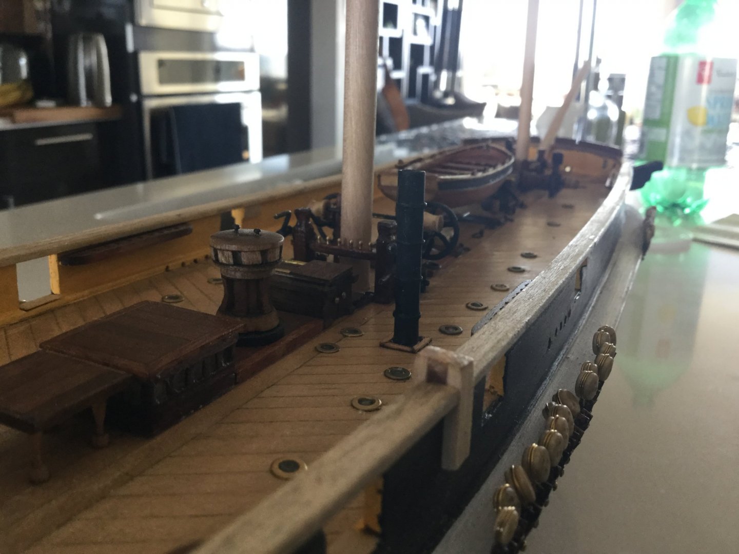
-
There's nothing wrong with your bow planking that can't be fixed with a bit of sanding. The plank that is sticking out a little can be fixed down by applying a little thin CA glue and holding it down with your fingernail until the glue grabs. Anyway, don't worry about the bow, it will be covered by the metal armour anyway. Nobody will be able to see it.
-
I don't know how Keith did his, but I ("other Keith") made my windlass, which is more or less the same, in sections. I drew a plan of the completed windlass, then fitted suitable lengths of dowel into my dremel tool and turned them into the requisite drum shapes using files and bits of sandpaper. I used a file to make teeth in a few dowel discs, and then sandwiched it all together on a rod. I used the cheeks from the original kit windlass, although I modified them with a bigger timber piece at the front, and used a drill and square file to make square holes for the capstan bars. I used a similar technique for my capstan. I'm assuming Keith did his in a similar way, because they look more-or less identical (which I find comforting).
-
Oh I like that stovepipe! Now that really does look the part. I will be interested to see how you manage the glazed windows on the skylights. I found that to be the part on mine that caused the most amount of frustration. I ended up taking a strip of that darker veneer that comes with the kit and backing it with painter's tape, then carefully cutting windows into it. For "glass" I just used a thin strip of sellotape and fogged it with CA adhesive. To be honest I thought it looked like a dog's breakfast but I tried all kinds of other methods like building tiny window-frames the proper way, and I just wasn't able to make it look any better. Once I trimmed it all with slivers of veneer on the outside I thought it looked OK. Mine is at least an improvement over the "jailhouse" look with the brass bars. In order to fit the requisite number of windows I had to sever the top from the bottom of the little plywood box from the kit and get rid of the corners. They are too thick. The "roof" is now supported on the little window-frames. It was all extremely fiddly.
-
I suppose; that's how one steers a sailboat even now. However, somewhere-or-other there's an account of Erebus and Terror pausing somewhere on their departure to have the compasses calibrated. Calibrated in this case meaning compensated for the various iron stuff in the ship creating a magnetic field, like the railway locomotive sitting in the hold behind the mainmast! They would have been calibrated to a specific location on the ship. I persist in my belief that there had to be something more elaborate than a box sitting on a table, and as we know, other ships like Trincomalee and Victory have nice big binnacles in plain view of the helm. I think the copper portable compass in your picture being lashed to a bracket (to keep its orientation constant) on the roof of the skylight is the simplest explanation.
-
I found the binnacle cabinet being lashed to the skylight a bit problematic too, because the skylight was meant to open on the top for fresh air. I can't work out where else it might have been. However, it's an operational necessity to have the compass in full view of the helmsman. It must have been somewhere immediately forward of the wheel, in full view. I've ordered Matthew Betts' book too, so I'm expecting we'll have lots of conversations about that when it comes out later this month! That copper binnacle looks very sensible. I still can't think of anywhere it could have been other than the roof of that skylight!
-
The azimuth compass was a different instrument from the magnetic compass, similar to an astrocompass for finding true north from the sun's position in high latitudes. The ship had magnetic compasses too. The TV show is not perfect but for what it's worth there is a scene in the programme that briefly shows the magnetic compass housed in a binnacle box lashed to the top of the aft skylight. It's one of the things I've been pondering for my model. I find it difficult to accept that the main magnetic compass was situated on that table with the mizzen mast and running rigging blocking it from the helmsman's view. An azimuth compass on the other hand needs a level surface and you can't steer by it; it's (I think) used for taking stationary "shots" to provide corrections for the main direction-finding instruments.
-
The most important reason to replace the windlass drum, other than the casting quality, is that the casting only has a single pawl, but the Terror's bell is mounted on a pair of pawl bitts. So the double pawl bitts are shown in the kit, but don't match with anything on the drum. Keith your work is fantastic. I will be ordering a copy of Mr. Betts' book as well. Very soon your ship will be ahead of mine! My work has kept me so busy I can barely keep my house in order. I haven't been on my real boat at all this month. My "Terror" is on a shelf in the lounge so I don't forget about her. I really like how you've carved some angled bits of wood to represent the iron forgings at the foot of the windlass cheeks. They look good and solid. I made mine from brass sheet and they don't represent the solidity of these parts as well as your wood ones do.
-
That looks just fine, the line holding the end of the boom up is a "topping lift" and would have probably gone to the mast on one side or other of the sail. However, on models without sails, I think it looks nicer (in my amateur opinion) to do it the way you have, because it suggests the outline of the sail and visually fills in that space. Besides, on boats with this type of sail, there is often a flag-halyard that does go exactly there. Often, pennants are flown from the tip of the gaff. Those white-metal boats are the devil to paint. I find white-metal takes paint better if you wash it with strong soap -NOT washing-up soap for dishes, because it often has oily stuff in it to make your hands feel nice after washing-up. You need to use a more aggressive soap like automotive degreaser. Or you can use a solvent like acetone or methyl-ethyl ketone. After that you must not touch the object until you have primed it, because even the oils in your fingerprints will prevent the paint sticking nicely. I think your ship looks great. There are so many parts to these models, I honestly feel like it is a Sisyphean task. I congratulate you on nearly being finished.
-
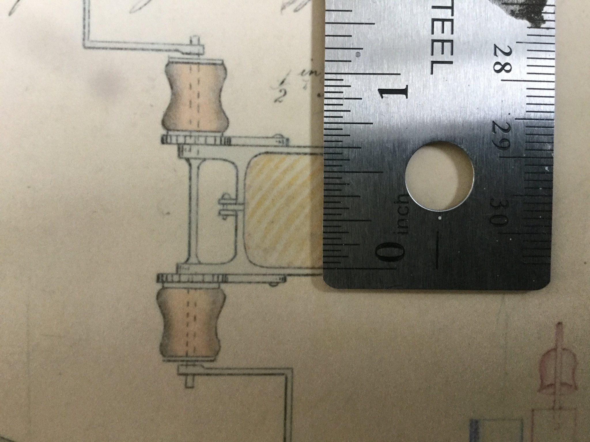
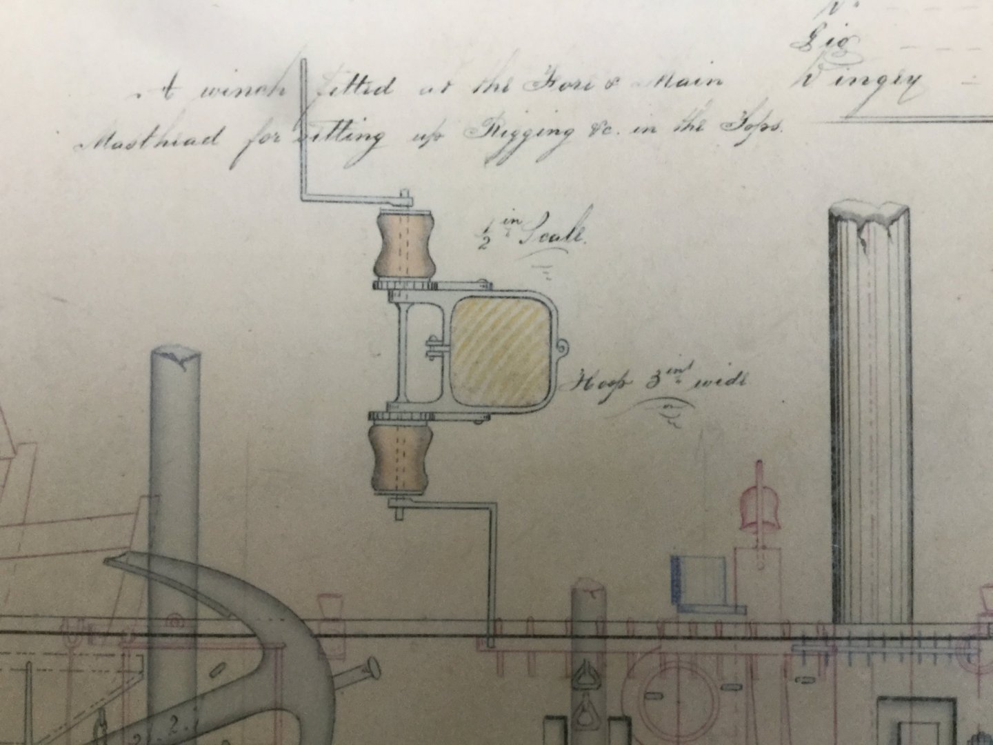
It's my pleasure to help with "HMS Terror" research. Your experience with rigging will be a great help to me when the time comes! The note above it reads "A winch fitted at the Fore & Main Masthead for setting up Rigging §c. in the Tops" Here is a close-up picture of the winch detail. It is not in the same scale as the main drawing: it's 1/2": foot scale. So I included a ruler in the second photograph. Additionally the drawing notes the "hoop" is 3 inches wide.

-
Hi Keith, before you get too far with the mastheads and mounting the topmasts, the ship's 1845 draughts show a set of hand-cranked winches mounted to the main and foremast just above the tops. I suppose you could build them at any time, but it might be easier to get them on there before you permanently affix the mast caps. If you like I will take a picture of this detail and try to read off the measurements. I've never seen these masthead winches depicted on a model or drawing before, so it's an interesting detail to include in my opinion. They look similar to the winches I've already built on my model at deck-level.
-
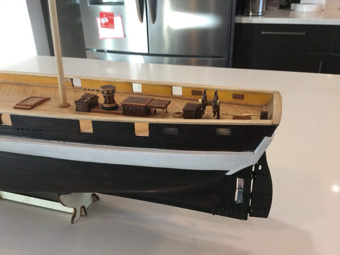
I'm fairly certain the boom would be supported by a "topping lift" which is a rope that goes from the tip to somewhere up in the mast. At the mast end it sits upon little wedge-shaped wooden blocks or a solid ring attached to the mast, and has a metal or rope ring called a "parrel line" with little rollers on it called "parrel beads" that goes around the mast. Unlike a small boat, when the sail is furled, it actually is tied up to the mast and the gaff, which is supported by the throat and peak halyards. So you can definitely include the gaff on your ship without the sail, either hoisted up, or lowered and lying secured on top of the boom. If you enter the term "boom jaws" in "Google" you will see lots of pictures.
-
OK I got mixed up with what a "jib boom" is. I was thinking it was something like the clubfoot on a cutter that makes the inner forestaysail self-tacking. I see now all the foresails are loose-footed and the jibboom is simply the extension of the bowsprit. I need to learn to read all the words and relax.
-
Actually the slings for the yards and stuff like that looks pretty easily explained. I'm just going to need to pass some things by you before I put them in my ship. So far, just as an example, the forestay "preventer"? There's a diagram of one which is "wormed" to the stay (like on your "Victory") but mentions after 1840 it wasn't done this way.. Also the "jibboom" for examp,e. Do you think Terror had these? My sailboat was designed with a jibboom, but I removed it and rigged the jib properly. I don't see jibbooms on model warships, but Lee has it in his book. Another example: the futtock-shrouds; the book says that after 1840 or so they were tied to a "necklace" of chain around the mast rather than being tied to a batten in the main shrouds. ...Or, iron hoops around the masts, that go UNDER the "paunch" and cheeks; and iron rings that go OVER the cheeks but under the paunch, and TAPERING the masts down to 3/4 their diameter between the hounds and partners... There is a lot to process, and that's just the stuff I DO understand. And I thought I WAS pretty good at nautical jargon. It's a wonderful book, but I can see it's going to make me more neurotic about my model, not less. Luckily we have this website that allows us to share information.
-
Luckily it's not that bad, the holes in the deck are the correct size, but the tip of the bit mangled things belowdeck. They seem to step at the right height but have some fore/aft and lateral play which will be fine once I glue them in and rig up the shrouds. I got my copy of Lee's book today. There are a lot of nautical words in there. 😐
-
Looks like you found a better way than me. I tried to drill out the slots to the new size and now I think the slots aren't there any more because the main mast is pretty wobbly. I'll have to take care to make sure the masts are reasonably parallel when I rig the shrouds. Does look better with the linger masts now though. I had just enough dowel left to make new ones the correct length.
-
So Keith do you mean the Occre dimensions do not take into account the below-deck portion? They are too short by that amount? That is to say, the proper length should be their dimensions PLUS another few centimeters?
-
I was wondering the same thing, but I like to wait until someone else asks just in case it seems like a silly question. I was going to use some sheet metal I have stashed away including some tempered sheet-bronze from an ancient door-sweep, which I thought would be fun to use, but in the end I found the aluminium plates from the kit pretty easy to use. The exception would be where the armour overlaps the channel chock- I found the aluminium difficult to work nicely over this compound curve, and left it off. Maybe self-adhesive copper would be easier to work in that spot. Don't worry, my little Terror is still very much front-of-mind, it's just that the weather has been so uncharacteristically nice (in the subarctic hell in which I live) lately that I have been preferring to spend time boating and working in my garden.
-
You are correct. I feel that it's OK to blame Occre for just about anything you like. The most important thing in the framing stage of building is that the planks lie fair across the frames. You must sand and sand away until they do.
-
I agree very much with what David says here. My "HMS Terror" model is my first ship model. At first, I was satisfied with my work. But because I have no experience, my work improves. Then I look at my work from before and I am not satisfied with it. I would say that every part of the ship other than the basic hull, I have made at least two times. If you look in my rubbish bin you would find enough broken parts almost to build TWO Terrors: one nice one, and one very ugly one. Every time I replace something with a better one, I am happier in the end. It is no good having a part of your model that bothers you. It will never stop bothering you. Better to replace it. You can't really do any damage that isn't repairable.
-
Nice work. Contact cement is a terrible substance. Many of the outer planks on my model have "sprung" and have been glued back down with CA. I will not be tricked into using cobblers' glue on a model ship a second time!
-
Amazing the two ships are in the same scale! Victory is very, very large and Terror is very small. Also amazing both ships survive to this day, one under the sea and one above.
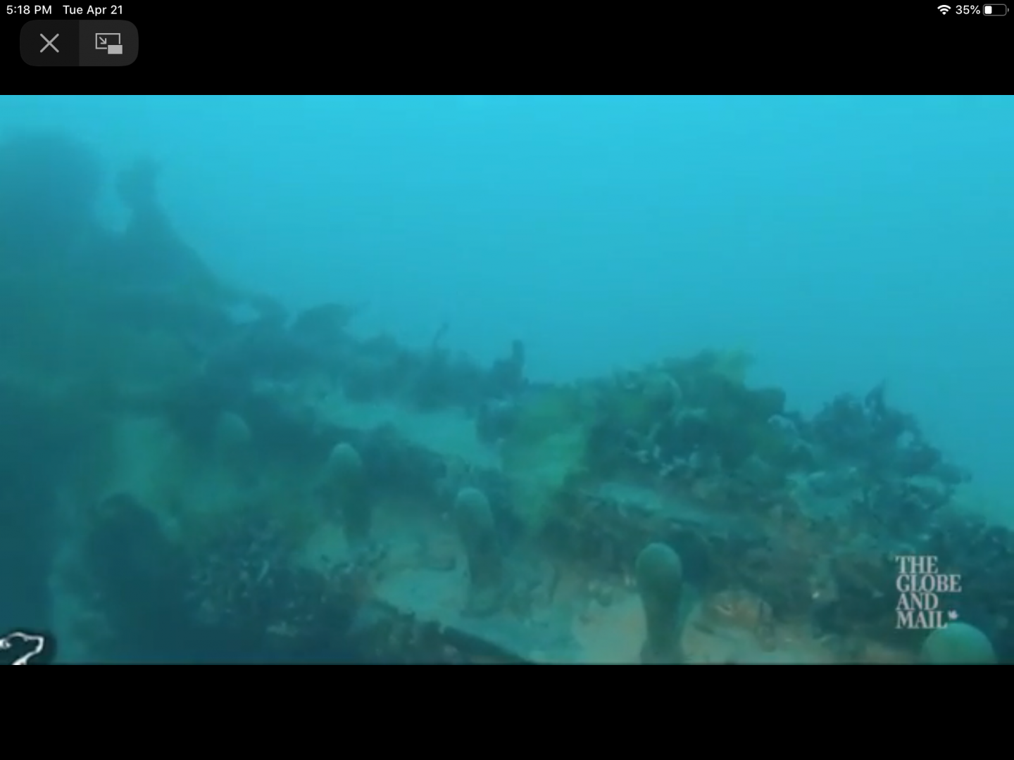
-
Yeah if you look really closely it looks like there's still some shiny spots on them where the varnish hasn't flaked away yet. Unbelievable how well-preserved she is. She must be the most intact Royal Navy ship from this era in existence, considering restored ones have a great deal of their original wood replaced. This seaweedy picture shows one of the bulwark pin-racks, which compares favourably to the size of the 5mm ones on the model.