HOLIDAY DONATION DRIVE - SUPPORT MSW - DO YOUR PART TO KEEP THIS GREAT FORUM GOING! (Only 44 donations so far out of 49,000 members - C'mon guys!)
×

Rik Thistle
-
Posts
864 -
Joined
-
Last visited
Content Type
Profiles
Forums
Gallery
Events
Everything posted by Rik Thistle
-
 powered the Stanley Steam Car to 150 MPH I hadn't heard of that...time for a read-up 😉 Thanks, Richard
 -
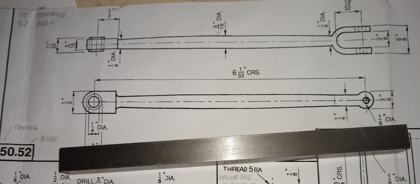
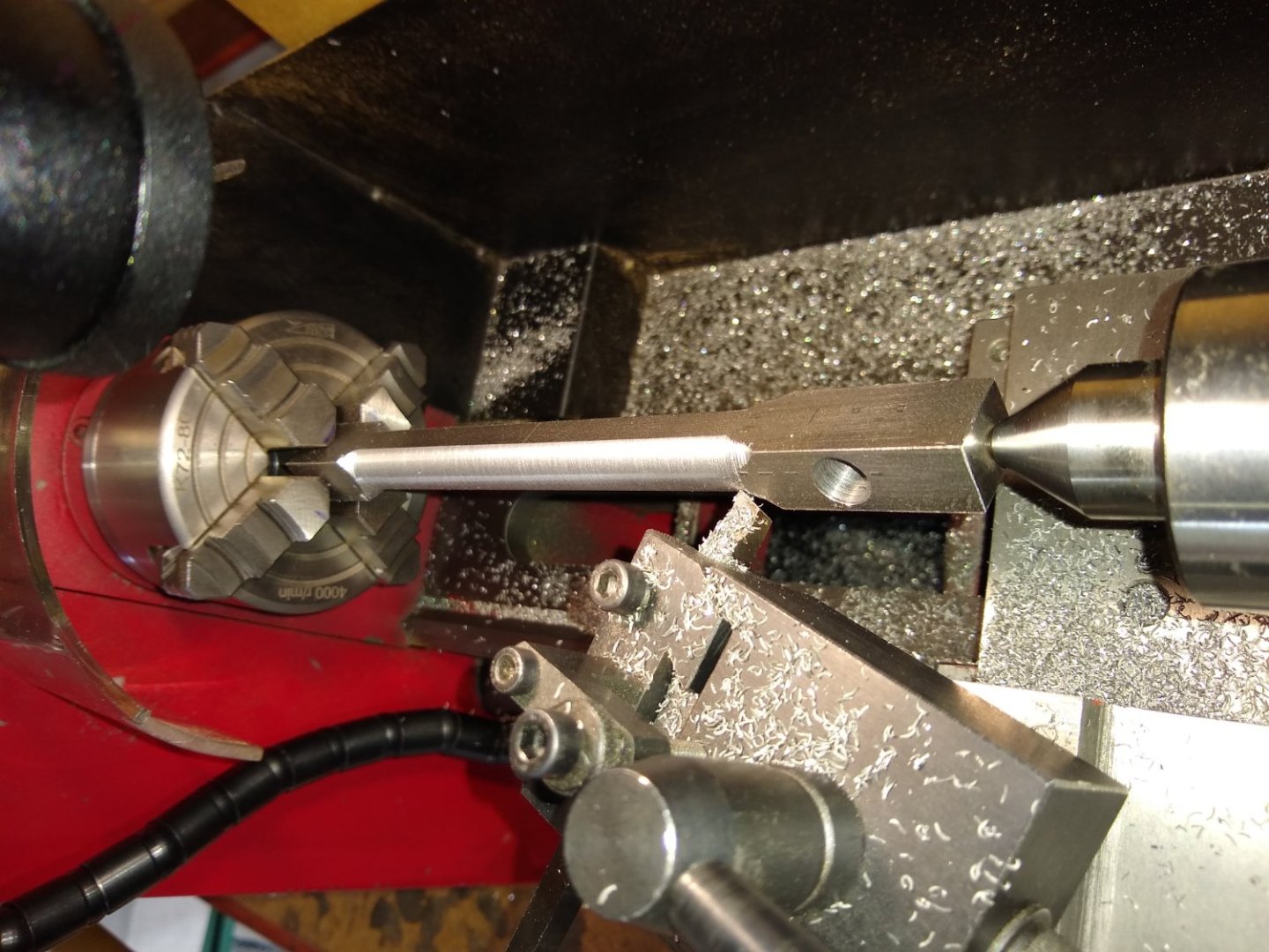
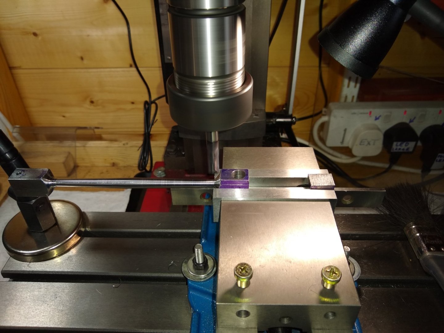
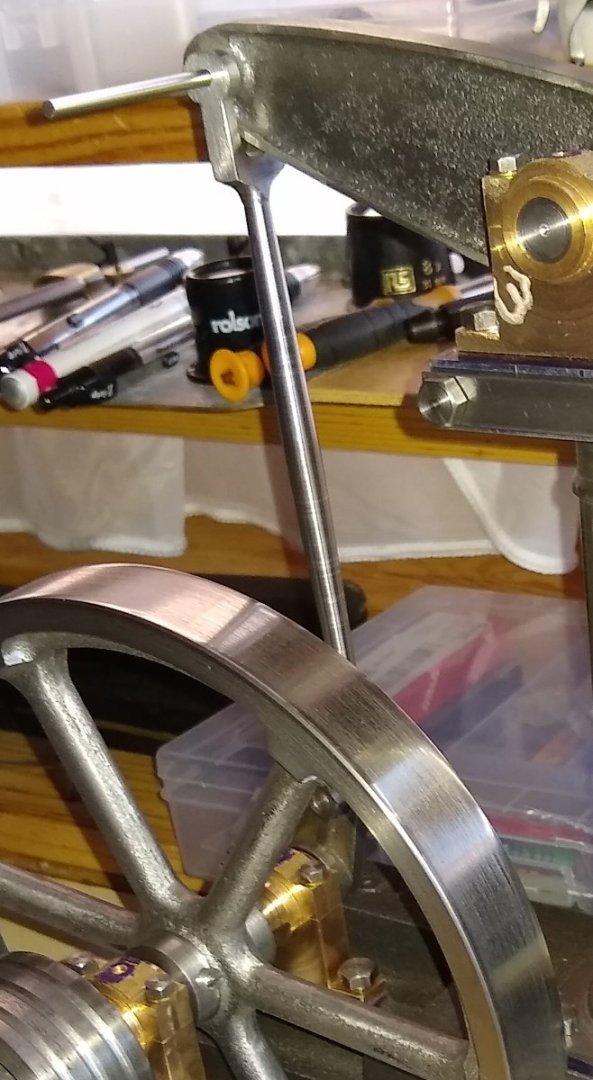
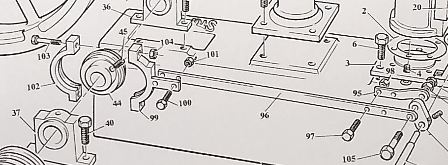
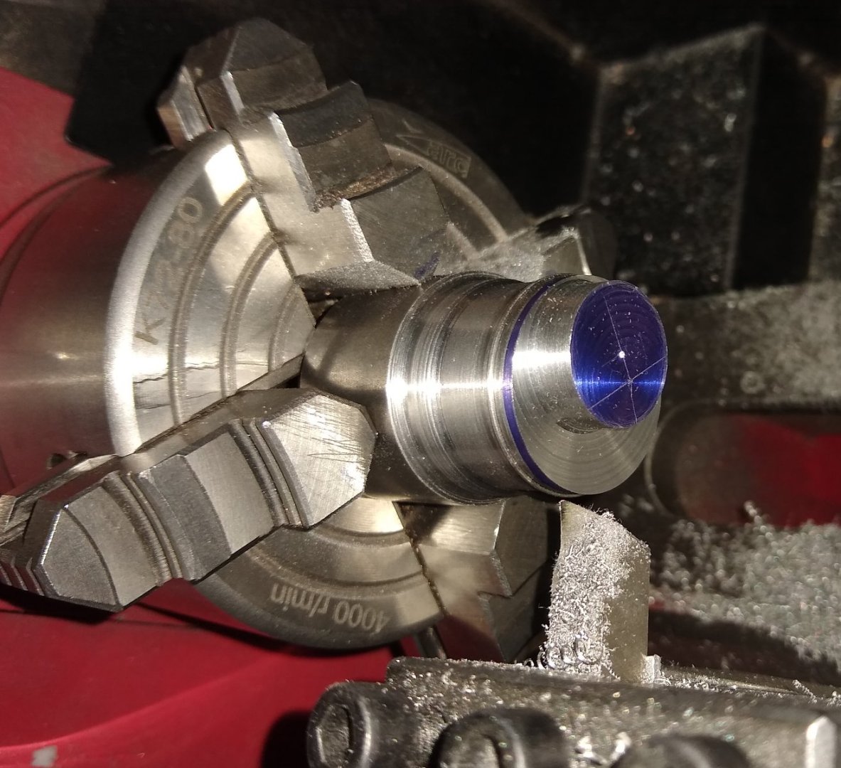
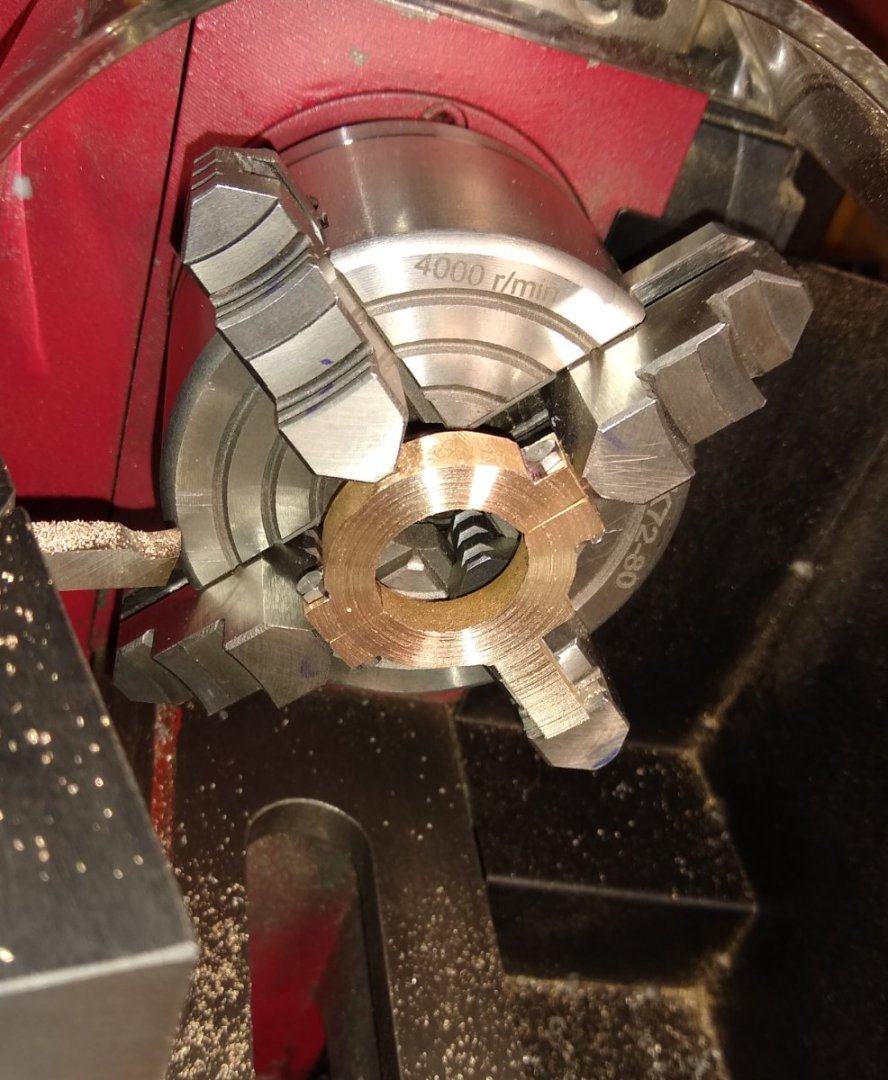
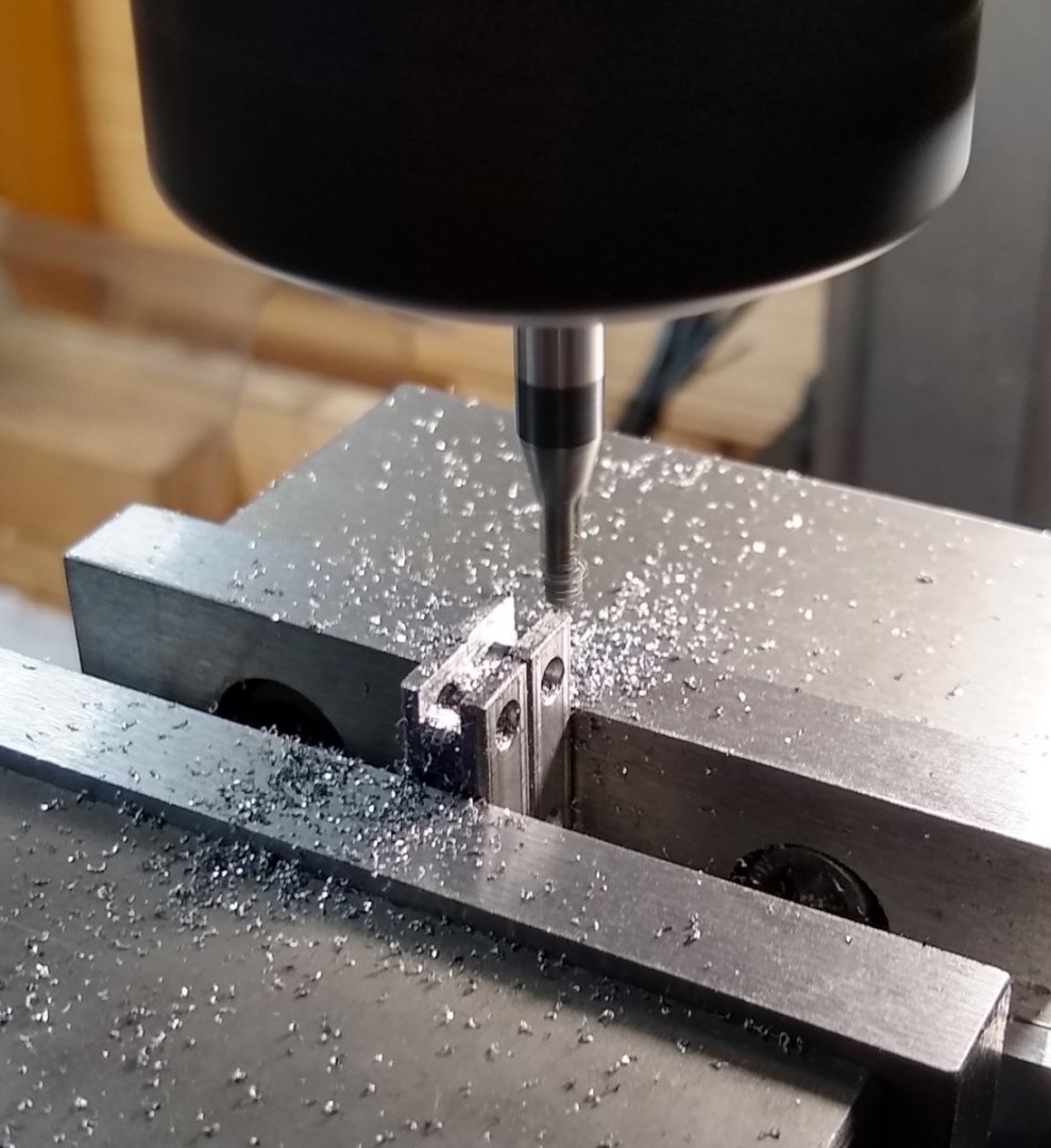
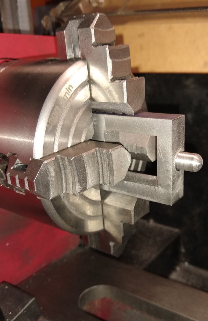
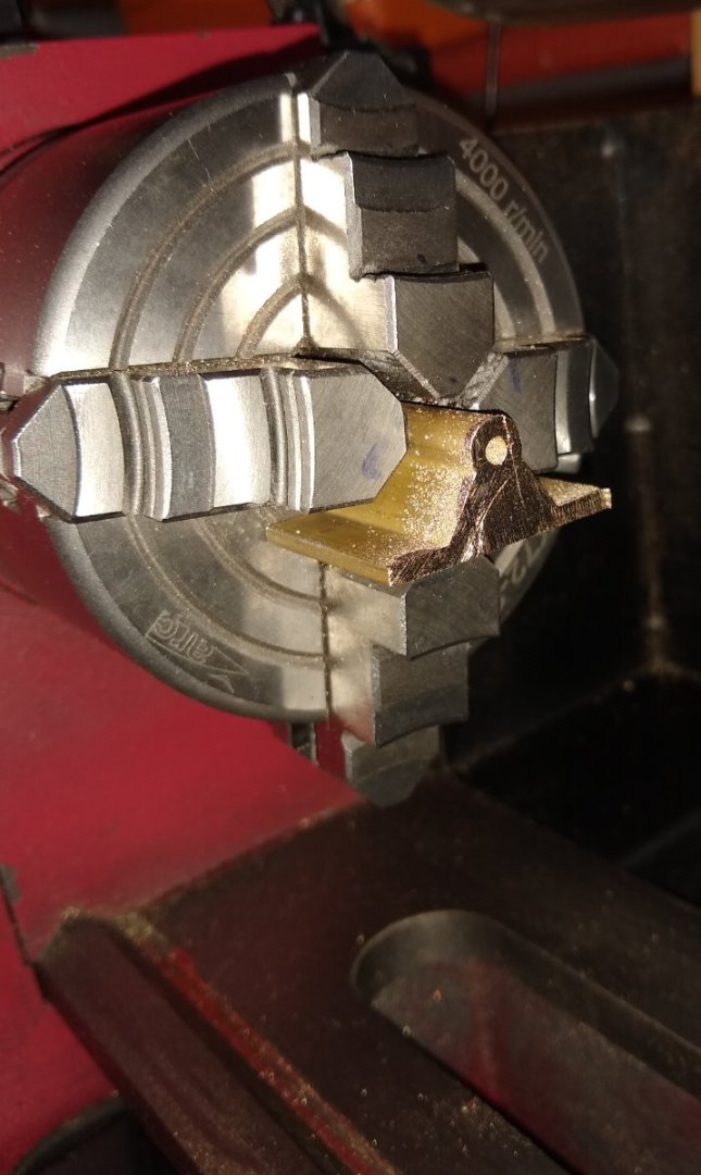
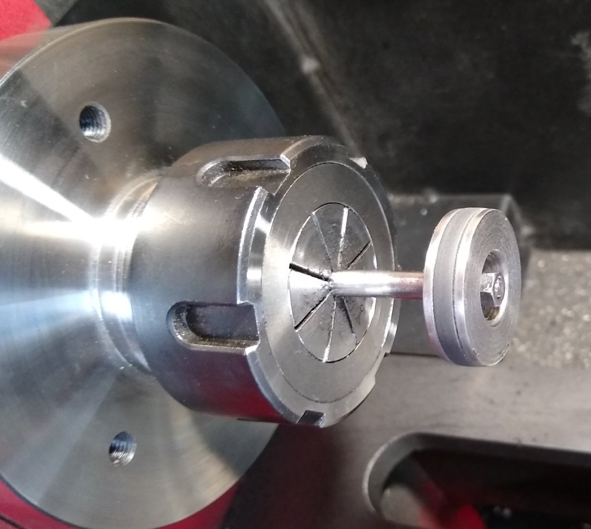
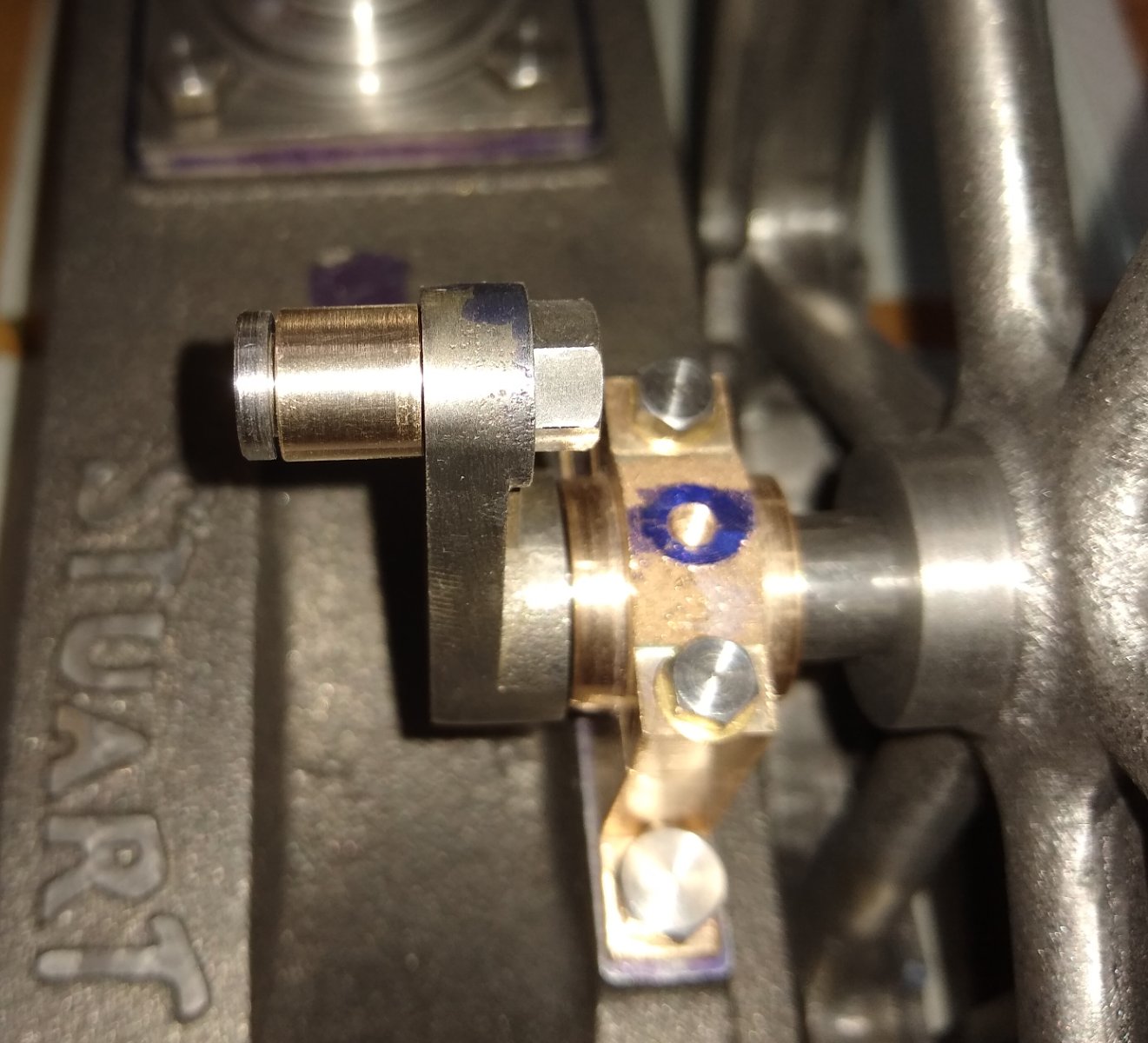
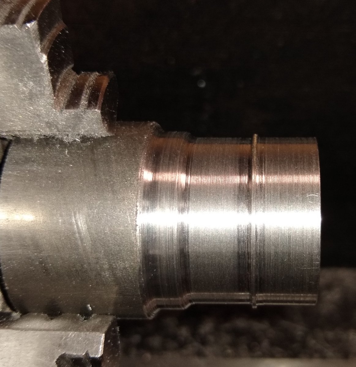
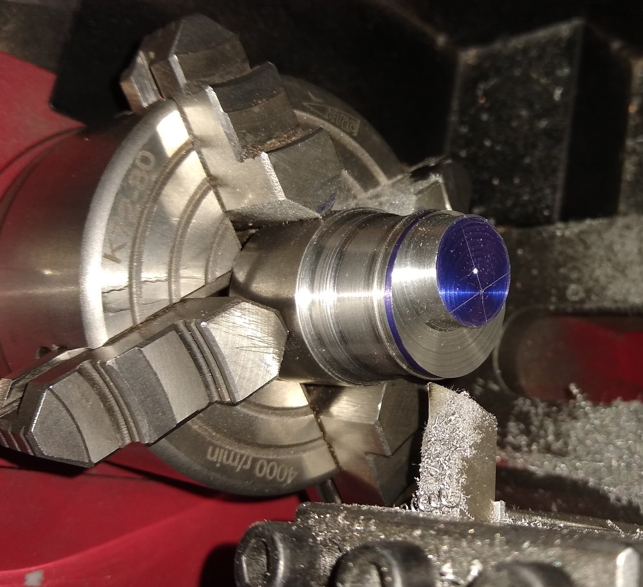
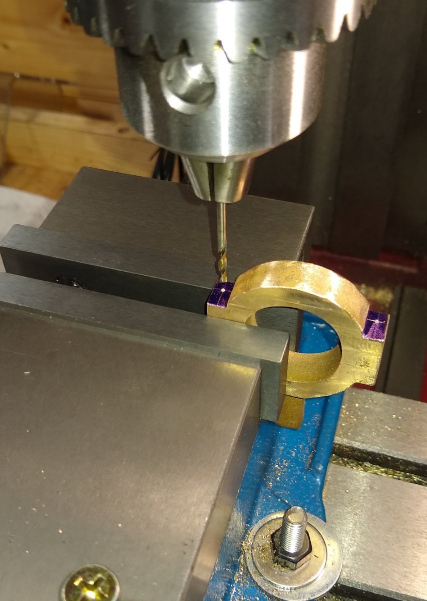
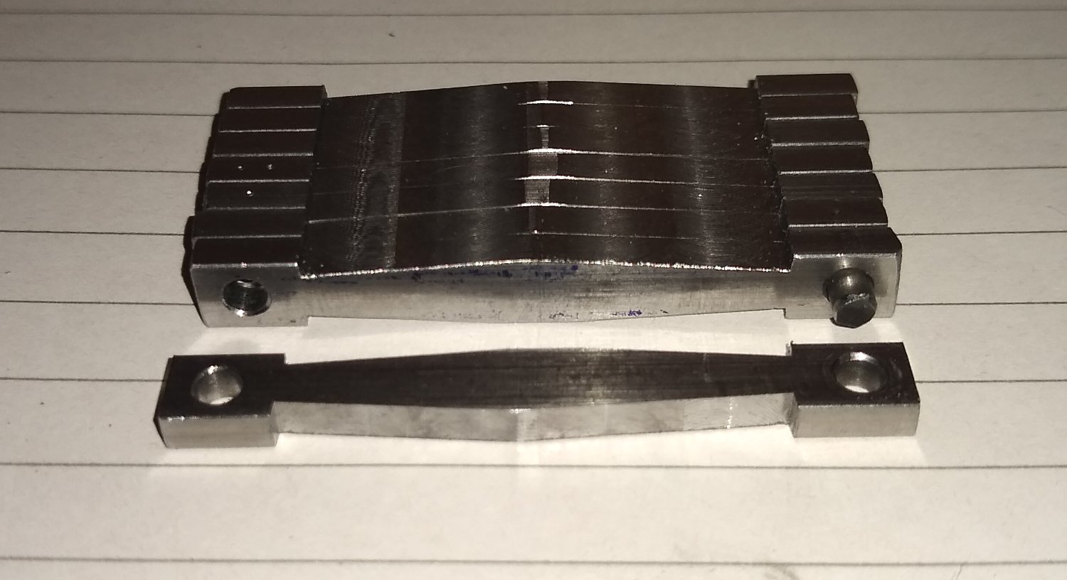
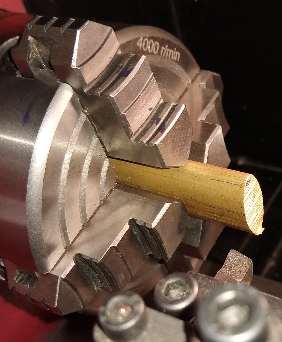
I'll make this post the second to last on the build. Today I'm looking at the Conrod, and the Eccentric Sheave parts. First the Connecting Rod (Conrod). It started life as a plain length of rectangular section mild steel. It would require turning and milling. As can be seen on the drawing extract below it required fishbelly'ing. Below, held in the 4 jaw at one end, live centre at the other. Being turned down to size before it the fishbelly profile was added. This is basically a double taper that was then 'curved' using files and emery cloth. And off to the mill for the end fixing regions to be shaped. Below, the Crank which is pinned on to the Crankshaft and pivoted on the end of the Conrod. The Crank has a Phosphor Bronze bush that is a press fit in the end of the Conrod. Below a part assembly showing the Conrod connecting the Beam to Crankshaft. Now on to the Eccentric Sheave parts. The Eccentric Sheave (Pt 44) is enclosed in the two halves of the Eccentric Strap (Pts 99 & 102). The sheave sits eccentrically on the crankshaft and is connected by a rod (Pt 96) to the valve mechanism. The sheave is held on to the crankshaft by a grubscrew (Pt 45) so can be adjusted to give the optimal valve timing. The sheave is restrained within the strap by a raised ring of metal ...this sits in a corresponding groove in the strap. It was 1/32" x 1/32" in size, which I felt was a bit small but I did get it to work smoothly. Another pic showing the boss that the crankshaft runs through, being machined. Below, the sheave (which arrived as a single piece gun metal casting) being drilled for two clamping bolts. It would then be slpit into two halves. One of the split halves having the inside clamping face cleaned up to size. Now in the lathe, ready to be bored out to size (for the eccentric) and to have the 1/32" x 1/32" groove cut. The finished eccentric assembly. L>R, the sheave inside the strap which is then bolted to the rod, and then the other end of the rod meets the valve mechanism. Well, that's it for the parts manufacture. I've missed out quite a few parts but hopefully included enough to give a flavour of what the build entails and maybe encouraged some other curious folks to have a go at 'steam engines' ;-). The final post will be painting, assembly and test. Richard


- 72 replies
-
- 11
-

-

-
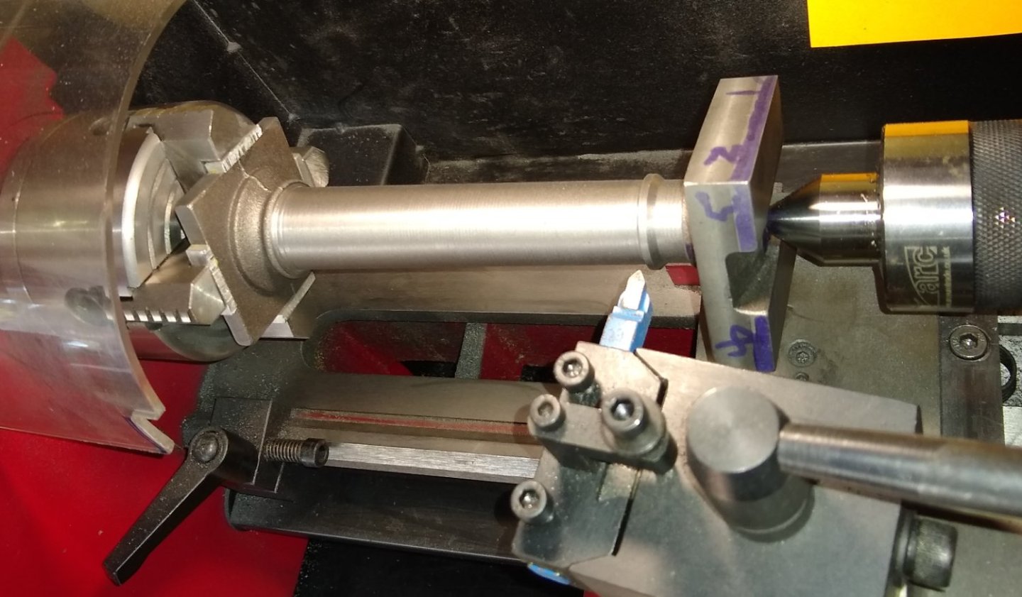
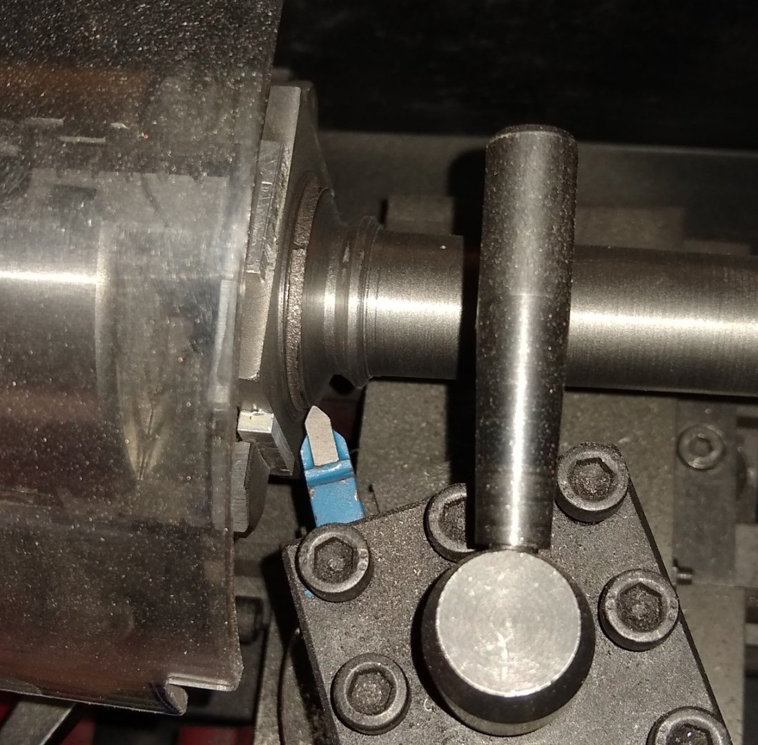
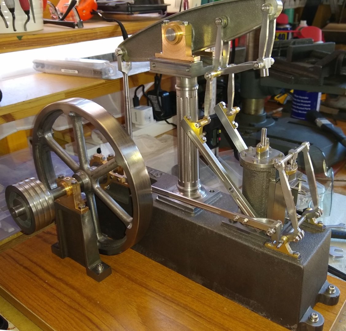
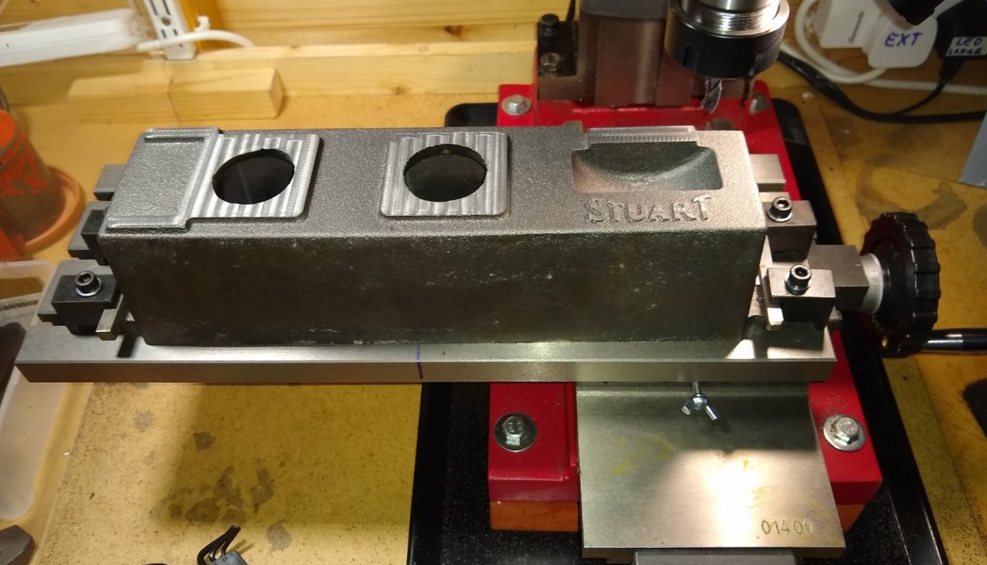
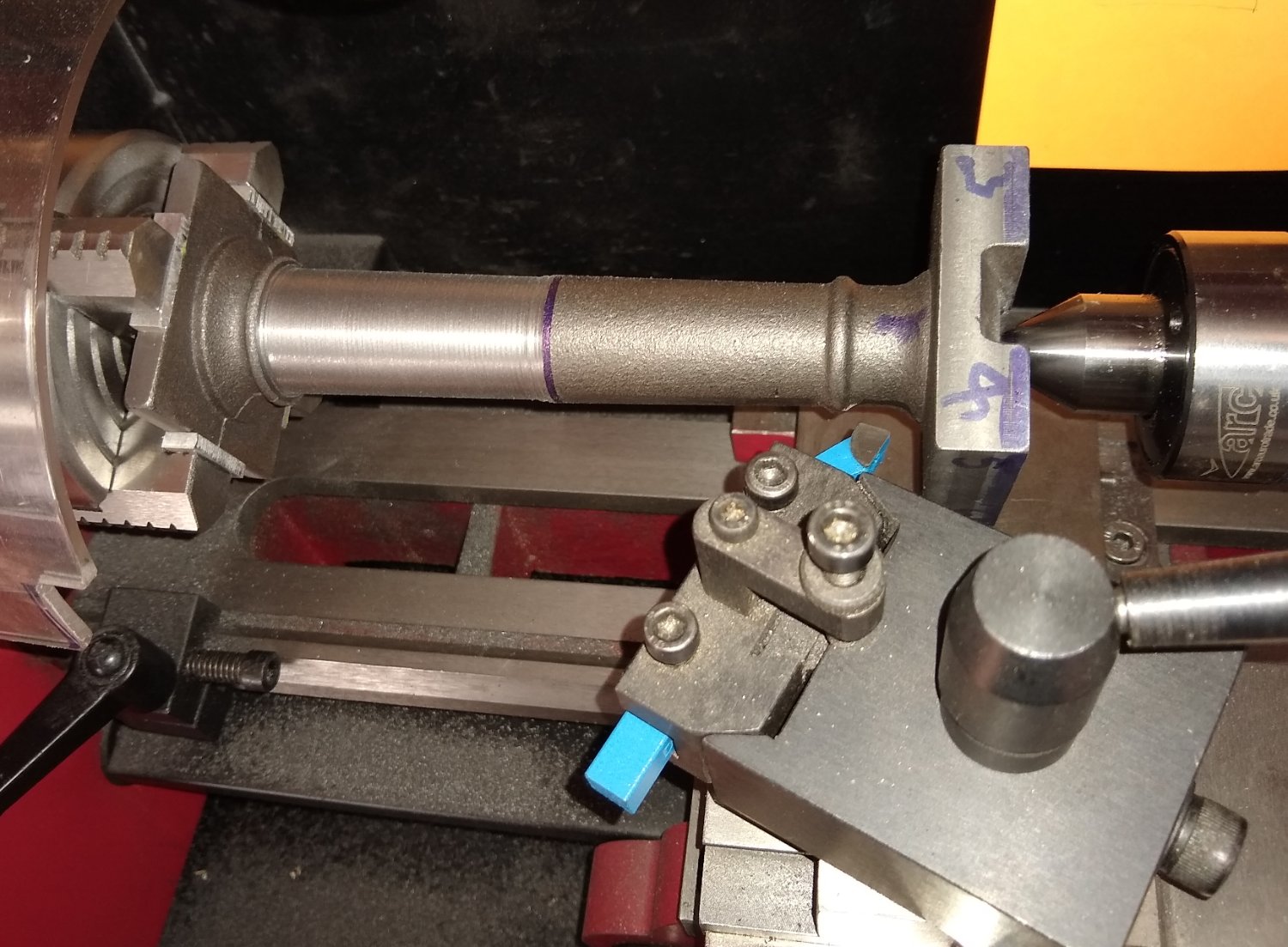
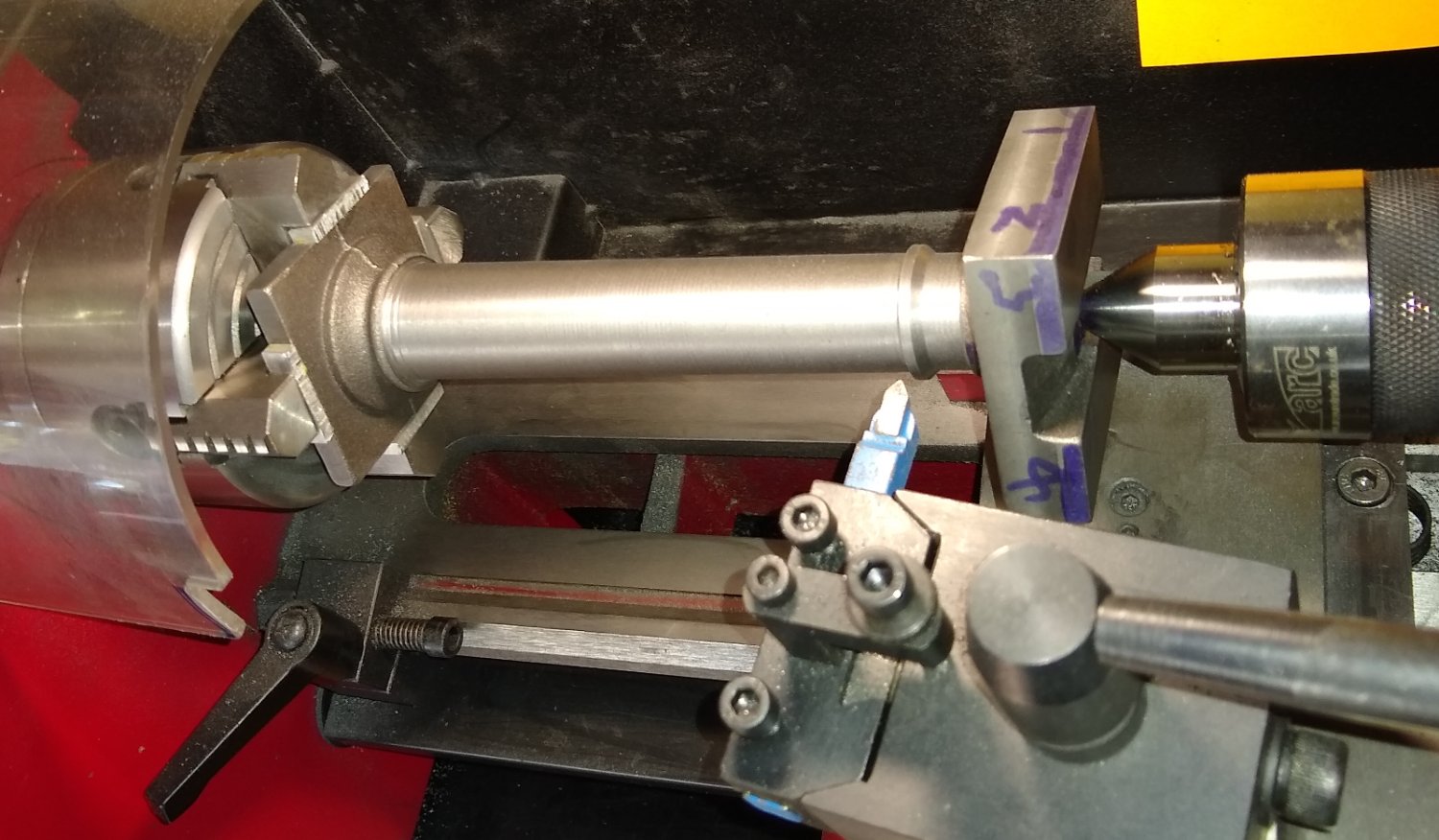
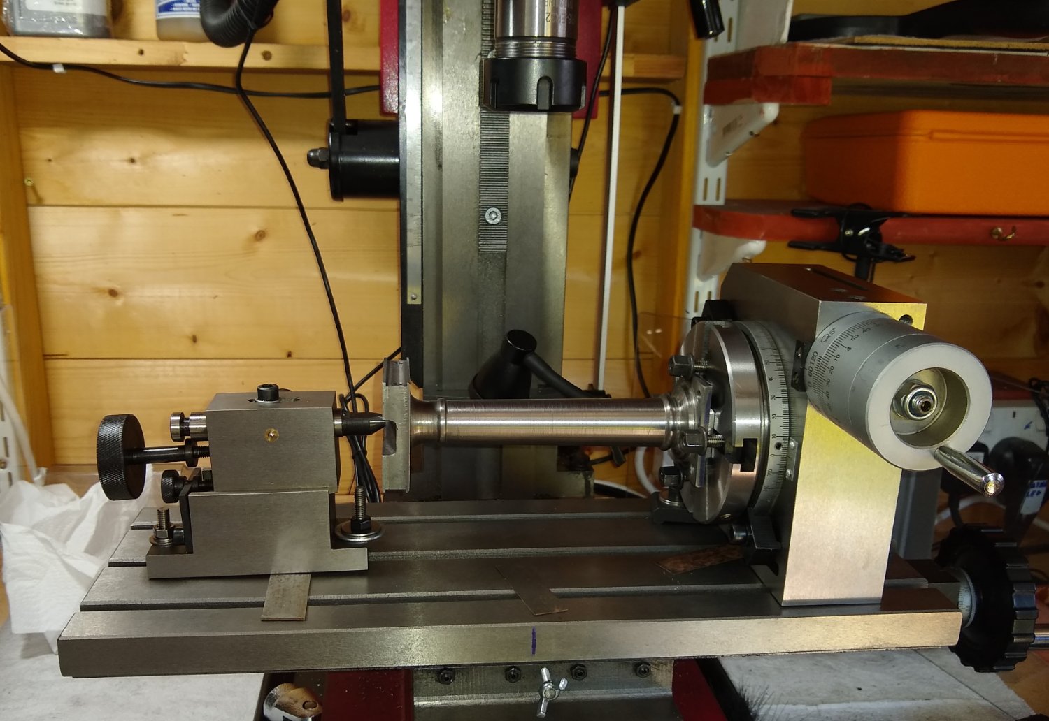
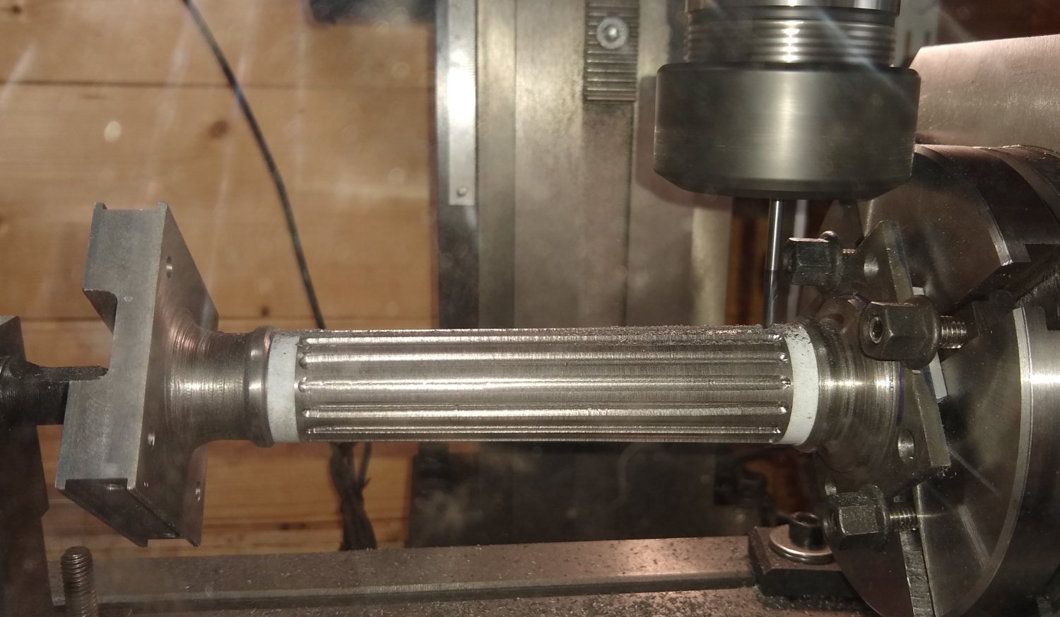
Hi all, Today I'll post some pictures and thoughts on the tapered Column manufacture. The Column supports the Beam itself. I believe that full sized columns were made as hollow castings. As with most of the larger parts for Stuart's model kits the column is supplied as a cast iron casting. It wasn't that rough around the edges regarding casting artefacts so less filing was required. I firstly mounted the column in the lathe to clean up the base's outer face ie the surface the column sits upon. I didn't notice at the time but the tapered part was oval in section and about 1 mm off centre from the square ends, which meant that if I had finished machined the square ends I would have later found there was not enough meat on the column to keep it co-axial with the ends. I did notice this issue in time, as it was being set up on the mill but I needed to do a bit of backtracking since I had already drilled a centre hole on the lathe in one of the square ends - I managed to fudge my way through that. Cleaning up and squaring the ends of the column on the mill. Now to taper the column on the lathe - it is held in the 4 jaw at one end and a live centre at the other. Again, because the lathe is on the smaller side of things, I needed to do the tapering in two steps since the cutting tool wasn't able to traverse the full length of the taper without clashing with the chuck. This meant the toolpost being reoriented along with the tool. Tapering pretty much finished and with a reasonable finish. Emery cloth brought a nice sheen to it. Profiling the curved lines of the ends of the column. I pecked away at this with the tool and then finished the curves off with a round file and Emery cloth. OK, now to the fun stuff - adding flutes to the column 🙂 The Stuart drawing doesn't ask for this but Beam models I have seen with fluting look that bit better. It's been decades since I used a Rotary Table (RT) so forgive me if my set up isn't traditional. I needed to get the top surface of the taper to line up horizontal, to match the cutting path of the 3mm round end cutting tool as it passed by. To do this I tilted the RT upwards. Unfortunately the RT Tailstock (although it has height adjustment) couldn't quite get it's nose up that high...so I tilted it upwards. This meant that the conical end of the dead centre in the tailstock was not sitting fully home in the centre drilled hole on the end of the the column - I got away with that, almost. The obvious thing to do would have been to raise the height of the tailstock and then point it downwards ...20:20 hindsight! I had calculated that I could make about 14 flutes at around 30 thou" (0.75mm) deep. It took 3 passes of the cutter to achieve the depth and then I indexed to the next flute position. All was going well until I was about 3/4 of the way around the column and I noticed the gap between the last two flutes was larger than expected. Something had changed....what I believe happened was that the tailstock dead centre had resettled into a different 'happy position' in the end of the column's centre. This was disappointing, but there was nothing I could do so, after a bit of recalculation of the indexing required, I continued on my way. My reasoning was, that from a distance and providing there were no Flute Inspectors around, no one would notice 😉 Below, the column sitting happily on the base. I think it looks acceptable. That's it for today, so catch you soon, Richard.

.thumb.jpg.5eb65c2eaf3341a2a9ccb89457262fdb.jpg)
.thumb.jpg.2a4ee6132ba5c62770f9c12f483b4e30.jpg)


- 72 replies
-
- 16
-
-
-
Rob, These static steam engine model kits are great fun. I'd highly recommend having a(nother) go 😉 Richard
-
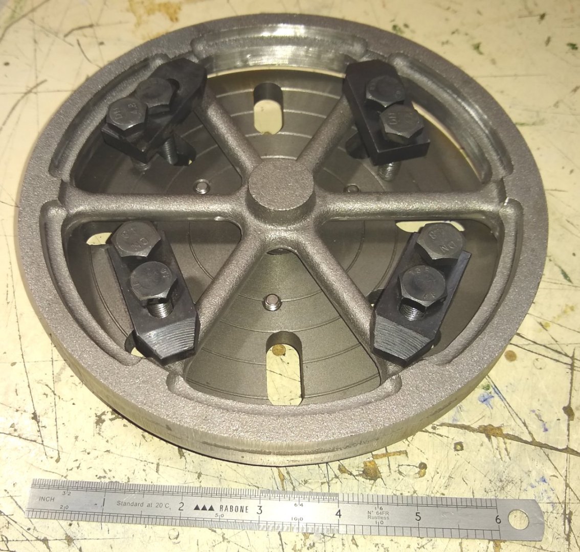
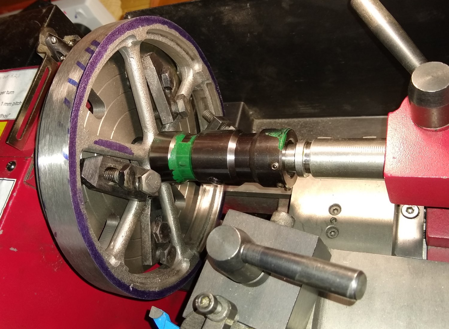
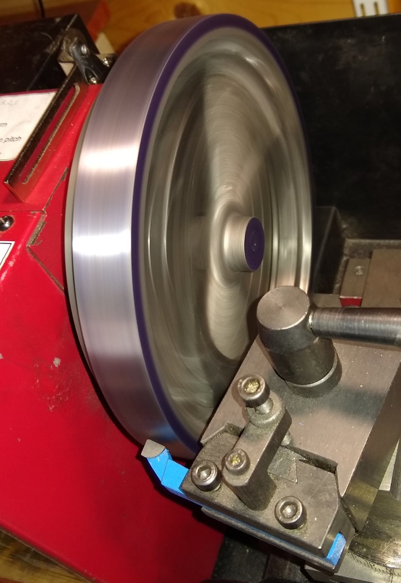
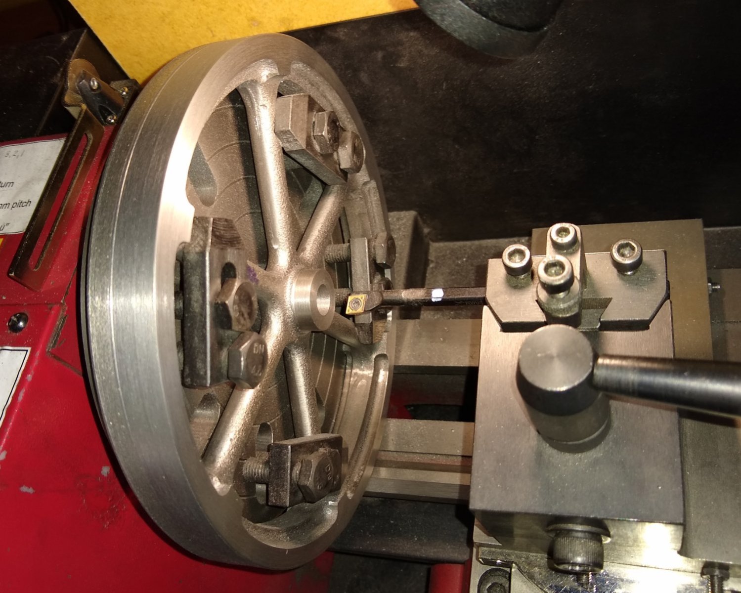
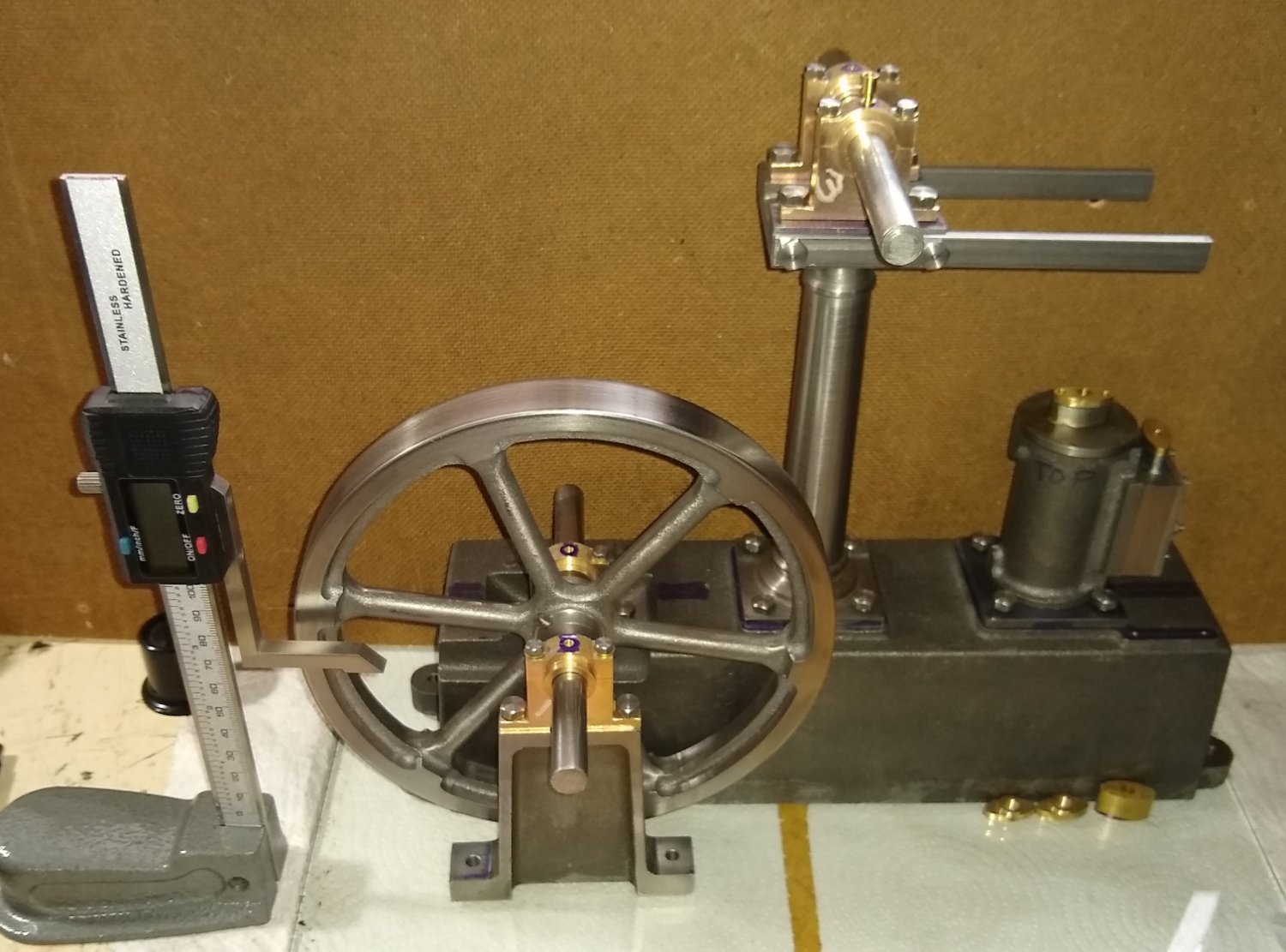
Hi all, Today a short post about the Stuart Beam engine Flywheel manufacture. The flywheel stores energy from the engine and that helps smooth out the pulses from the cylinder, and also encourages the crankshaft to continue in the same rotational direction when TDC and BDC are reached. The Stuart models cast iron flywheel arrives with a reasonable amount of casting artefacts and needs cleaning up before being mounted on the lathe. The lathe, a Sieg SC2, can accommodate a maximum diameter of 180mm ...the raw casting was larger than that. It's finished machined diameter is 177.8 mm (7"). After being cleaned up on the linishing belt there was about 0.5mm clearance from the bed of the lathe, which was fine. For a finished flywheel to appear to run smoothly to the eye one should carefully file the inner face of the rim since that cannot be machined. I also spent a good bit of time on the linishing belt trying to clear off the hard outer perimeter of the casting...I got most of it off but there were still some patches that gave my Carbide tipped tool a few moments. Below, the flywheel is mounted in approximate position on the faceplate, and away from the lathe to avoid a fight with gravity. Final alignment of the flywheel on the lathe was greatly aided by my trusty die holder which fortunately had the same end diameter as the boss on the flywheel. The four clamps were equi-spaced and didn't create much, if any, of an imbalance at the turning speed. Below, skimming the outer perimeter of the flywheel. Try as I may, I could never get the tool tip to cover the full width of the flywheel from one side - I resigned myself to having to finish that job by turning the flywheel over. Below, after part turning the outer surface and cleaning up the wheel face, I bored out the hole (7/16") for the crank shaft. I did need to buy a smaller boring bar than the ones I already had. The white dot was a rough indicator for when the tool was through the flywheel. Once done the crankshaft was a good sliding fit. You can also see the step on the outer surface of the rim which was as far as I could sensibly go - to finish it off the flywheel was turned over and re-clamped. Below, the finished wheel. It cleaned up nicely once I got the Emery cloth on it 🙂 The flywheel, and a few of the other rotating items are clamped to their axles by slotted-head grub screws. I don't feel this is entirely suitable for a number of reasons. The slotted head gets disfigured quickly (a socket key head is better), the axle gets marked (a flat needs to be added to the axle) and the grub screw can slip against the axle (again a flat will help prevent this). There are changes I plan to do. Catch you all soon, Richard


- 72 replies
-
- 11
-
-
fishbelly-shape Euler strut theory - I should have recalled that. pivot-pins Some of the pin material came as 1/8" stainless steel rod, so those I left alone, apart from adding threads on the end. Not being ground stock the stainless, IIRC, was not 0.125" but closer to 0.123"... but good enough for this job. Some of the other pins had stepped diameters ... the one shown in the pic with the 4 mm collet is 5/32" rod, with it's ends being turned down to 1/8" I should have mentioned I not only drilled the holes but did also ream them to size. tapping Yes, I tried using that method also when I first got that mill (SX2P), but the head has a bad habit of suddenly dropping if the clamping is a bit off. I also use the smaller taps in a pin vice held slightly loosely in the drill chuck. The pin vice knurling gives enough purchase to hand turn the (small) tap. Thanks for the inputs. Richard
-
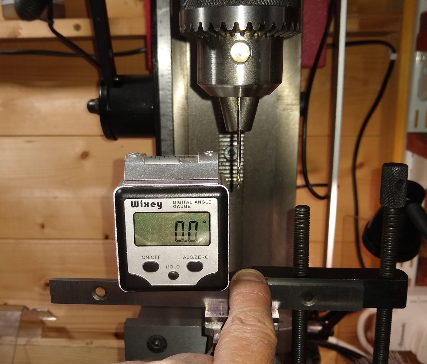
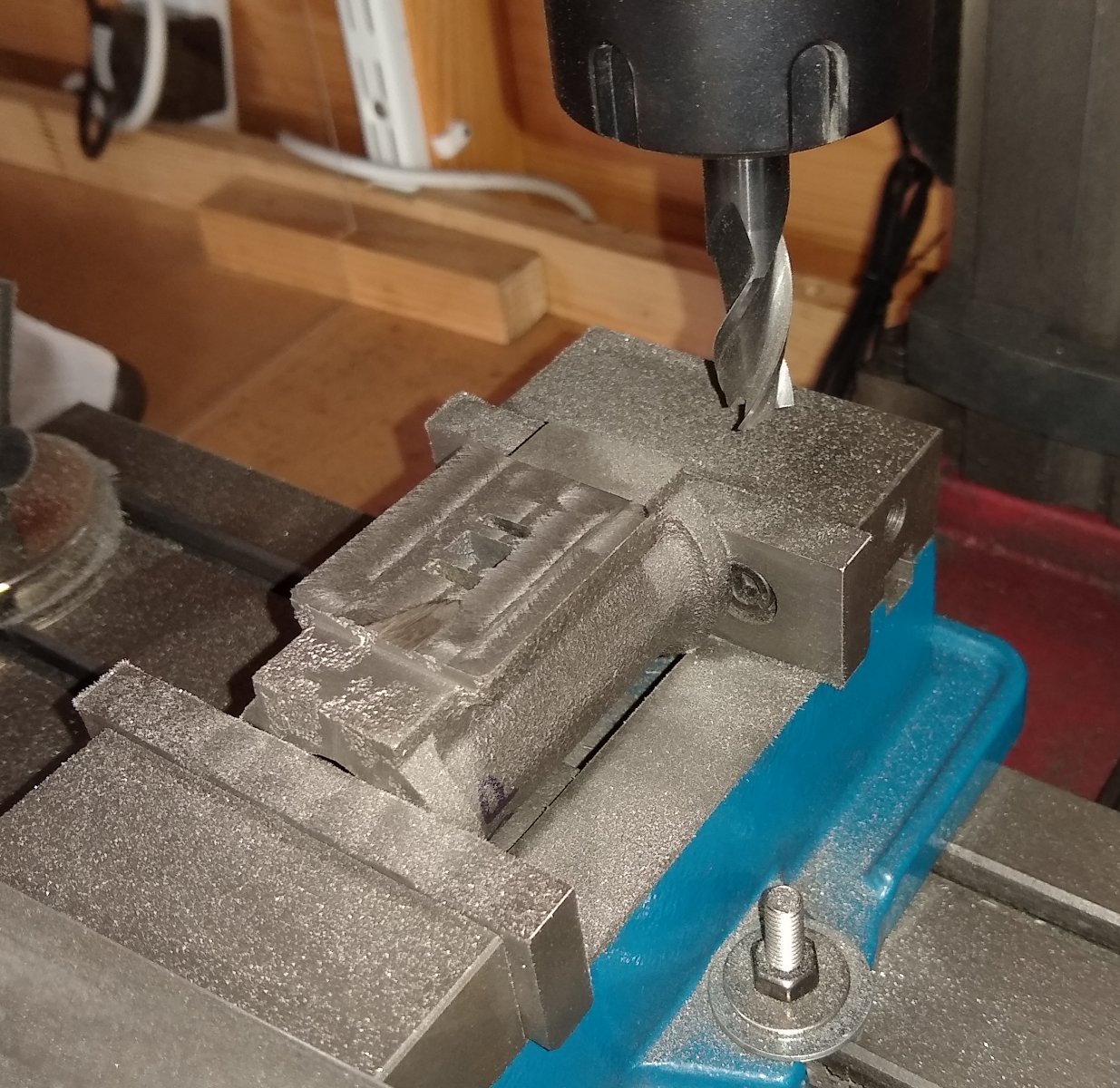
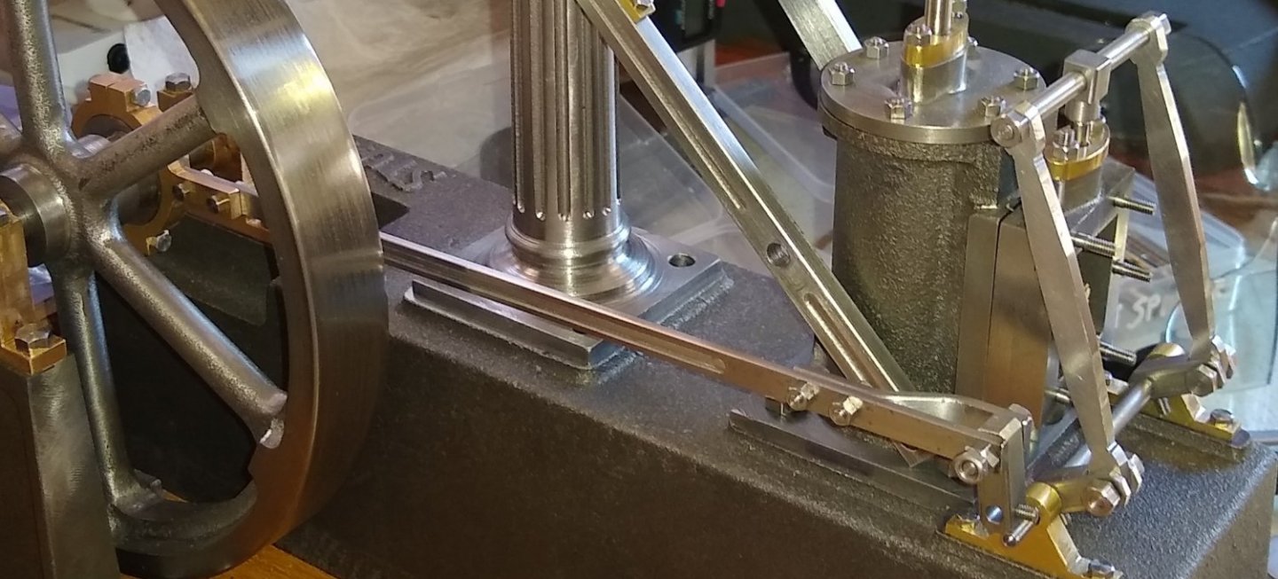
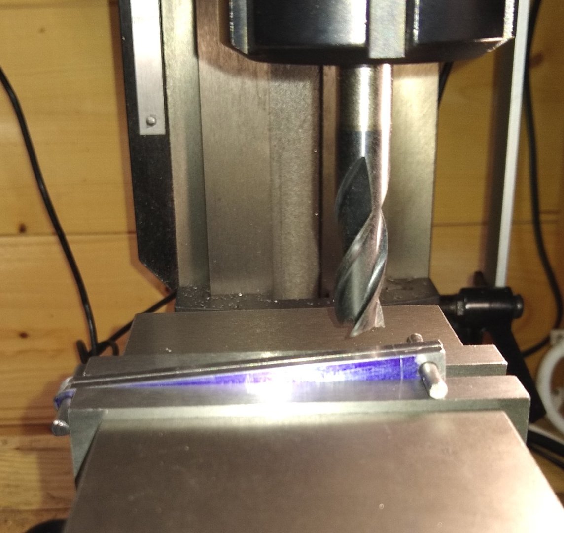
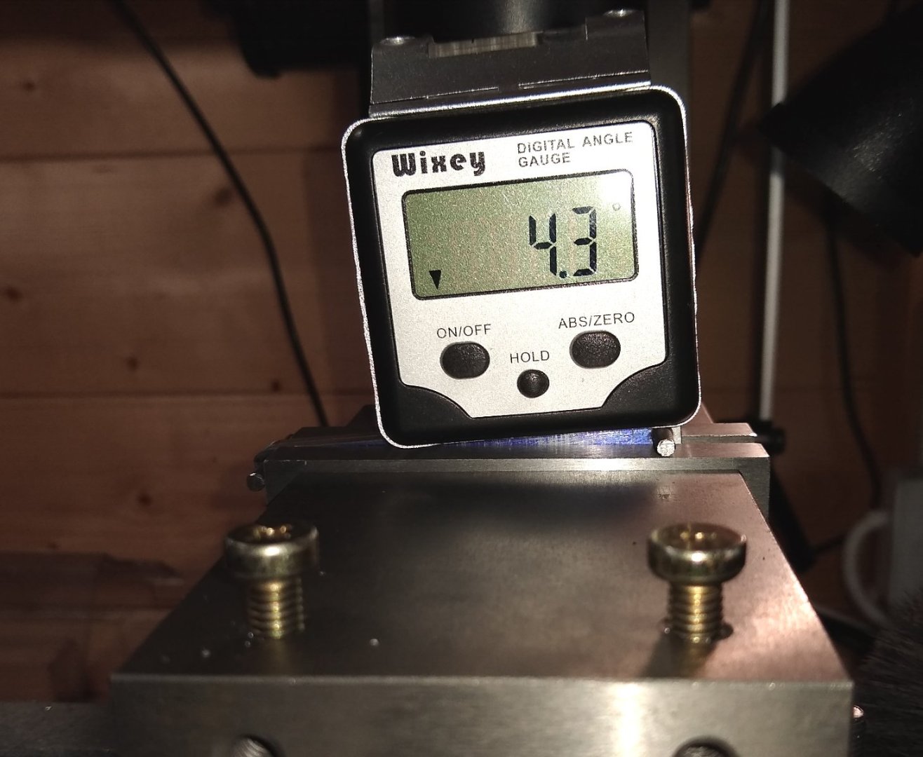
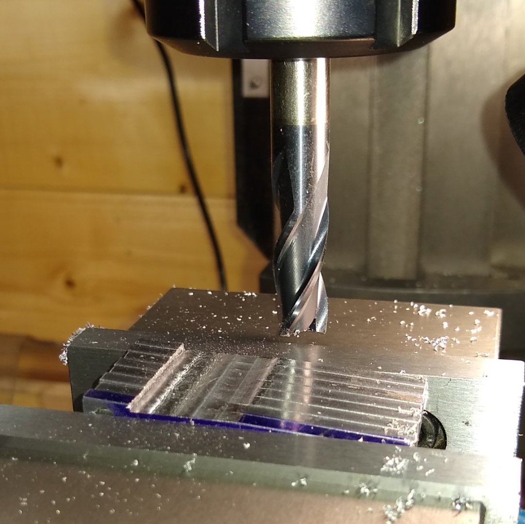
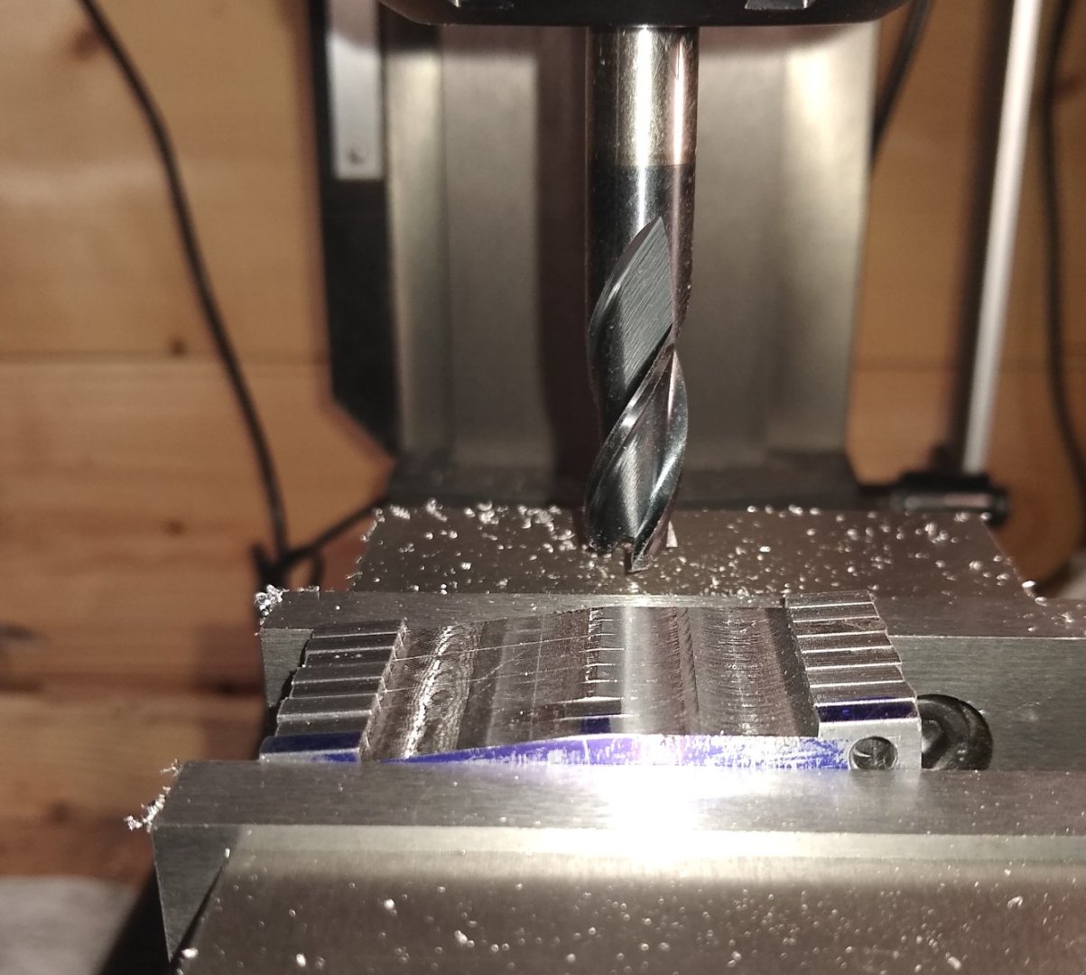
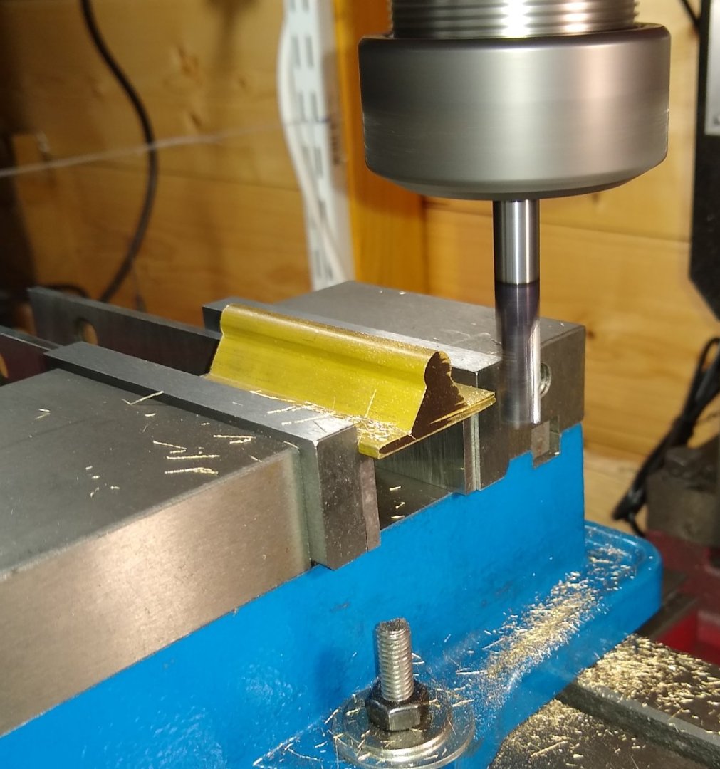
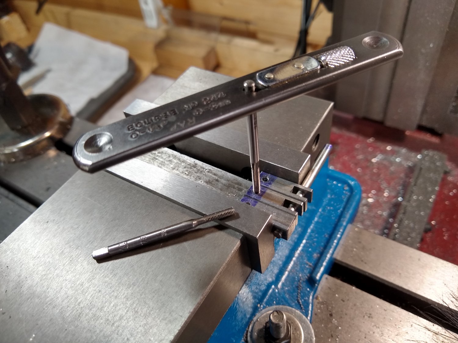
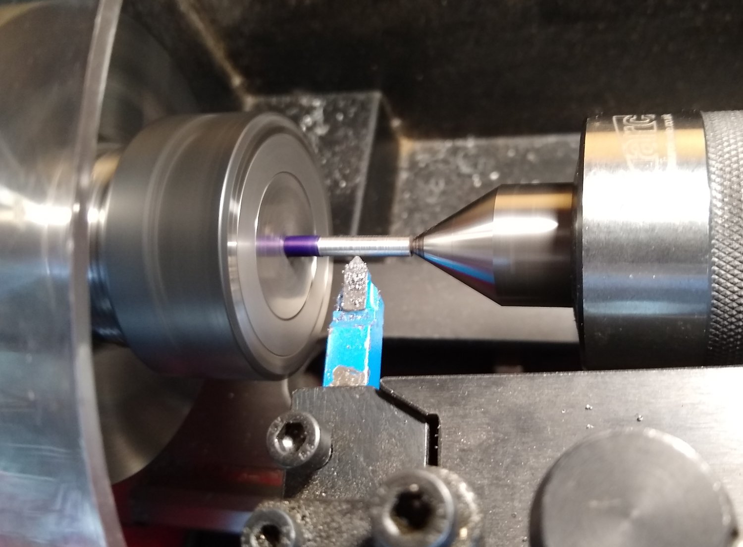
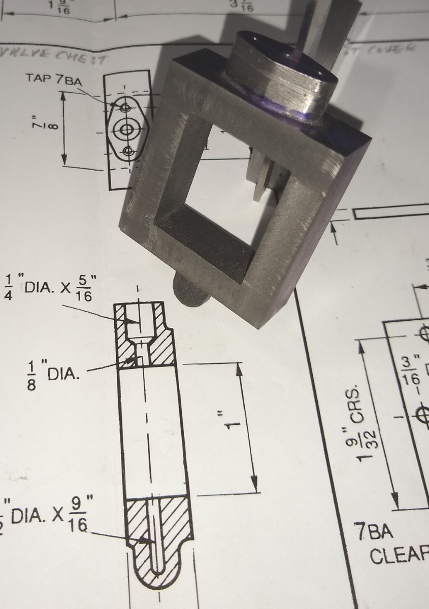
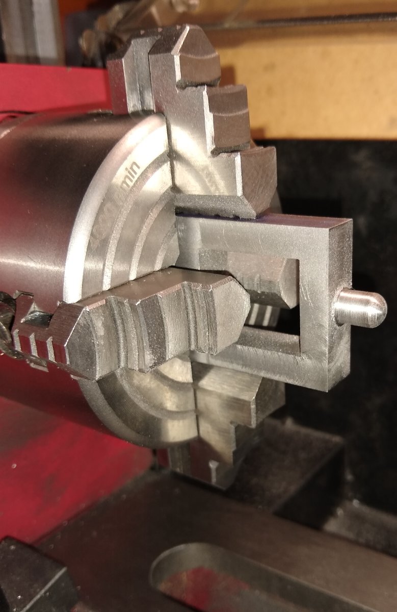
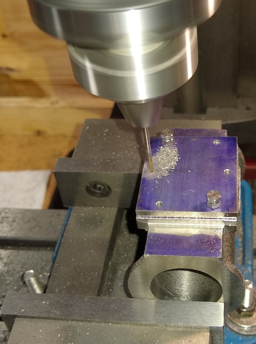
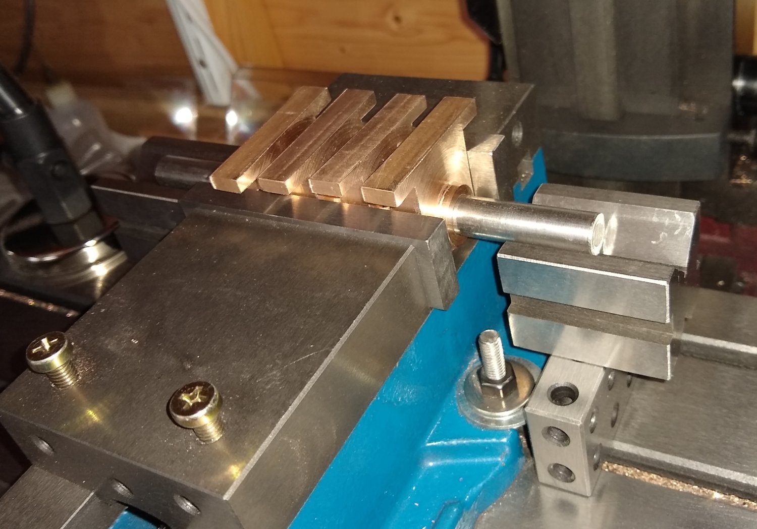
Hi all, Today, a short post on the Watt linkages, and the Valve Chest linkages. James Watt, regarding his linkage idea, wrote in 1784 ... I have got a glimpse of a method of causing a piston rod to move up and down perpendicularly by only fixing it to a piece of iron upon the beam, without chains or perpendicular guides [...] and one of the most ingenious simple pieces of mechanics I have invented. .... https://en.wikipedia.org/wiki/Watt's_linkage There were 8 off Watt links to make, plus two off Valve chest links. The Links are used in pairs. The linkages are usually given a fishbelly profile. I suspect this is done for looks, but any advice on that welcome. The fishbelly (on models) is achieved by mounting each linkage between centres in the lathe which allows an elegant shape that tapers from the middle to each end. I had a long thought about doing that but decided on a simpler process - use the mill to taper the links in one plane. Here is the pair of valve links in the mill vice, aligned with a pair of 1/8" pins. Below, to get a suitable taper angle I calculated that clamping the links at a 4.3 degrees slope was ideal. My Wixey digital angle gauge helped accurately set the angle. Below, the 8 off Watt links get the fishbelly treatment, again held in line with 1/8" pins. Reset the links and angle, and the other side is done. All 8 off Watt links almost completed. The ends of some need a bit of trimming, but since they were all to have their ends rounded anyway a file took care of that. The Valve Levers having slots cut in them. And then the Lever grub screw holes tapped. I tend to use my flat bar tap wrenches for most tapping jobs. But small taps don't have a guide hole in their end - I recently acquired a Starrett T Bar tap wrench which has a guide hole in its end so ensures vertically tapped holes - I think I'll be using it a lot more in the future. The Sterrett also feels extremly well made - the only drawback is that the wrench's cross-bar is much higher than the flat-bar one so has a higher wobble factor (assuming it isn't supported by the guide hole). One of the many 1/8" diameter pivot pins that the linkages use, being turned up in the lathe. Now a couple of pics of the cast iron Valve Chest. It's very similar to the 10V chest. It required mostly milling work. And a little 4 jaw chuck lathe work to round off the Valve rod dome - the tail of the valve rod always sits within the internal hole drilled in the dome. Using the cast iron Valve Chest Cover to spot fixing holes through onto the Cylinder itself. There are a number of brass glands required, for guiding steam in and out, and also for guiding the piston rod. For these Stuart supplies a length of brass extrusion that is turned to shape in the lathe, central hole drilled, parted off and then fixing holes added. Finally, we see the Watt linkages hanging from their bearing points on the main beam and entablature arms- the arms were still hanging loose at this point. Also the two Valve links are in place, connected to their levers which in turn are worked by the eccentric sheave on the crankshaft. Up next, in a day or two, should be the Flywheel 🙂 Regards, Richard


- 72 replies
-
- 11
-
-
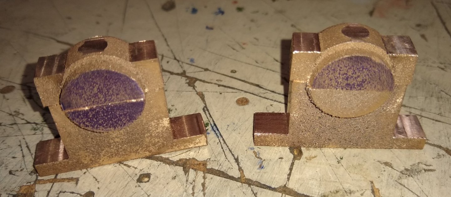
Roger, surfaces were often coated with Prussian Blue Yes, from what I've read recently there was quite a bit of fettling required to get a good rotating fit. Once electric motors became available I can see why they quickly replaced steam engines in many applications ie less maintenance and manpower required and overall, cheaper to run. Follow the money, as usual. I find steam engines fascinating and it is a shame they are no longer a part of our daily lives. However, nuclear power stations still heat water to produce steam so it could be argued that steam power is still very much with us. Richard
-
...housing was filled with molten Babbit- white-metal.... I didn't know that...very interesting and a clever solution, thanks. Richard
-
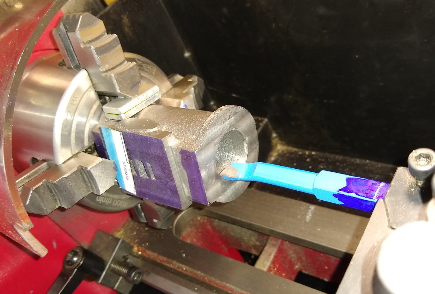
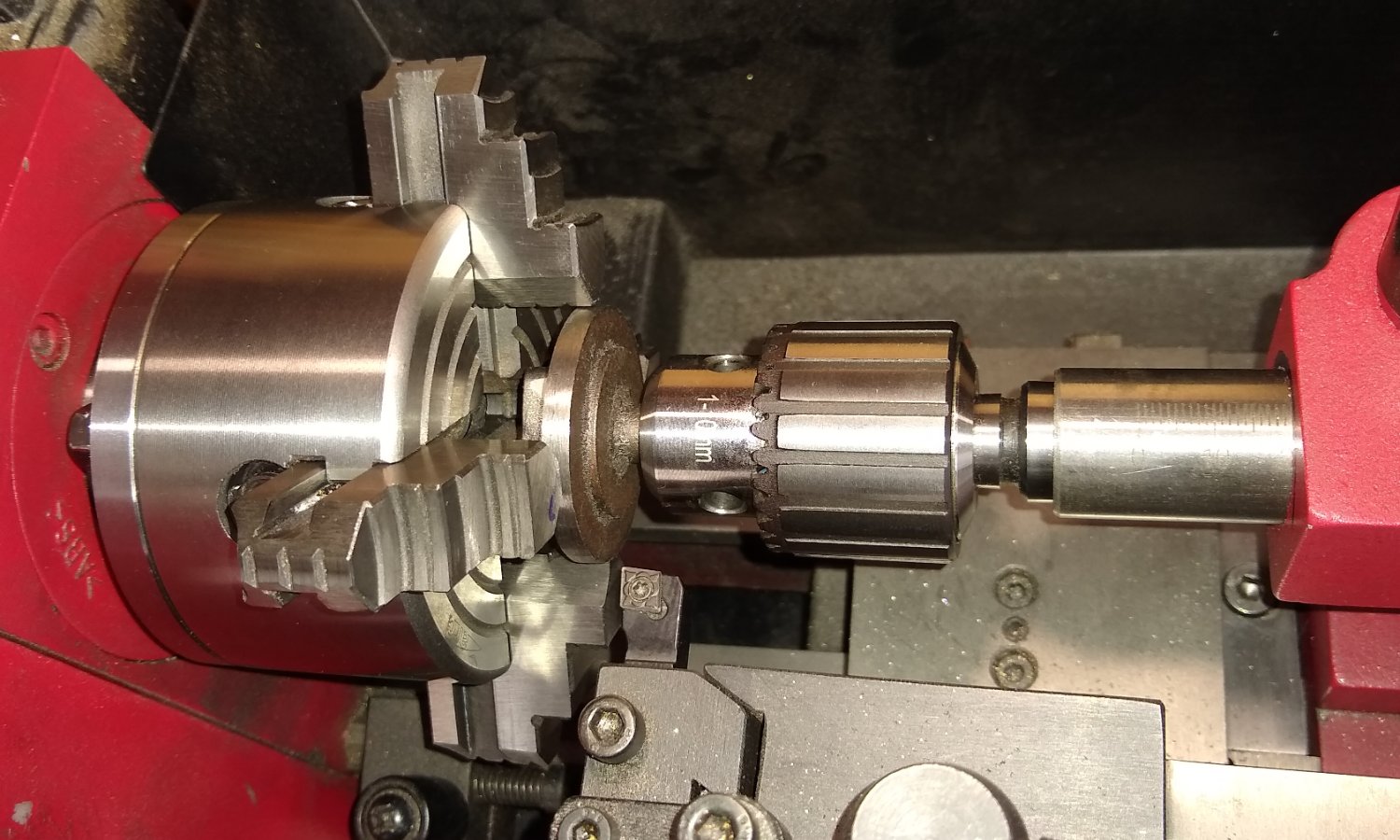
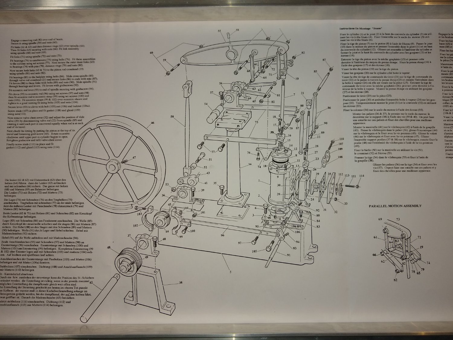
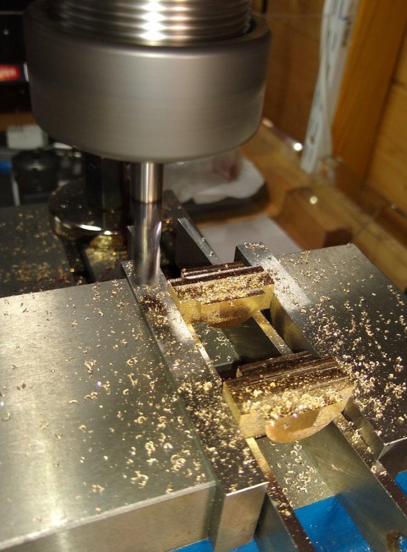
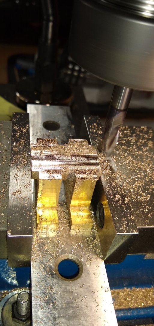
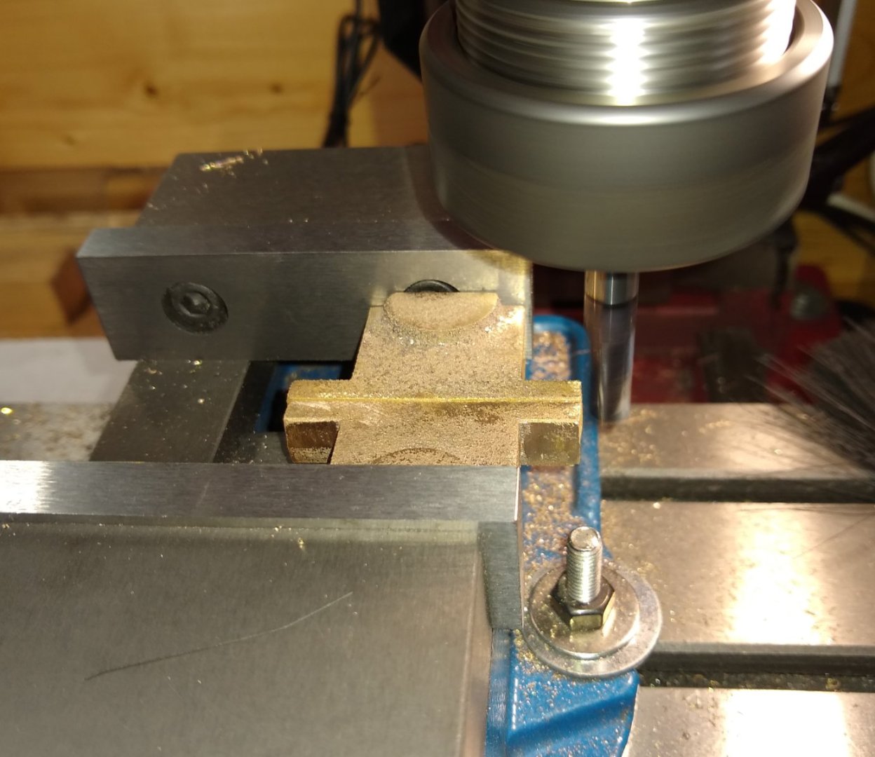
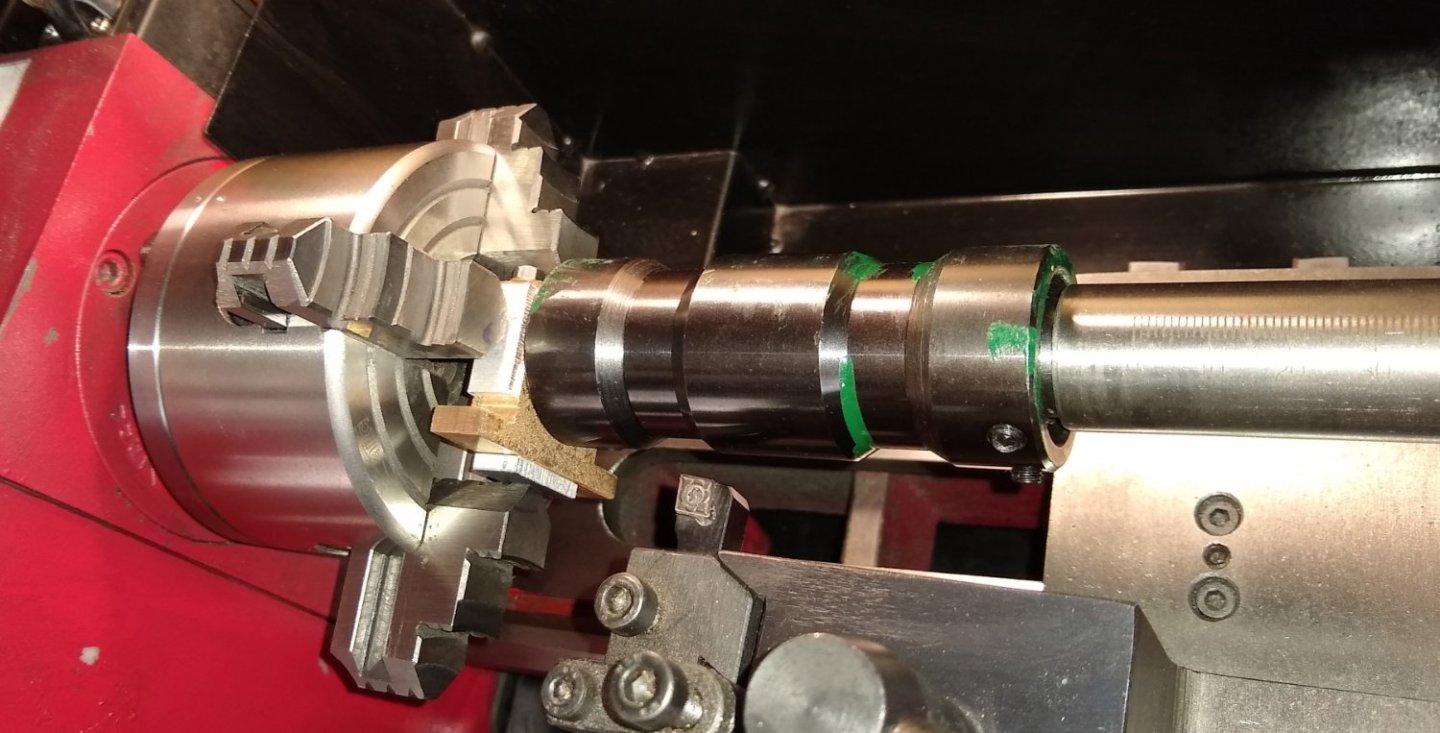
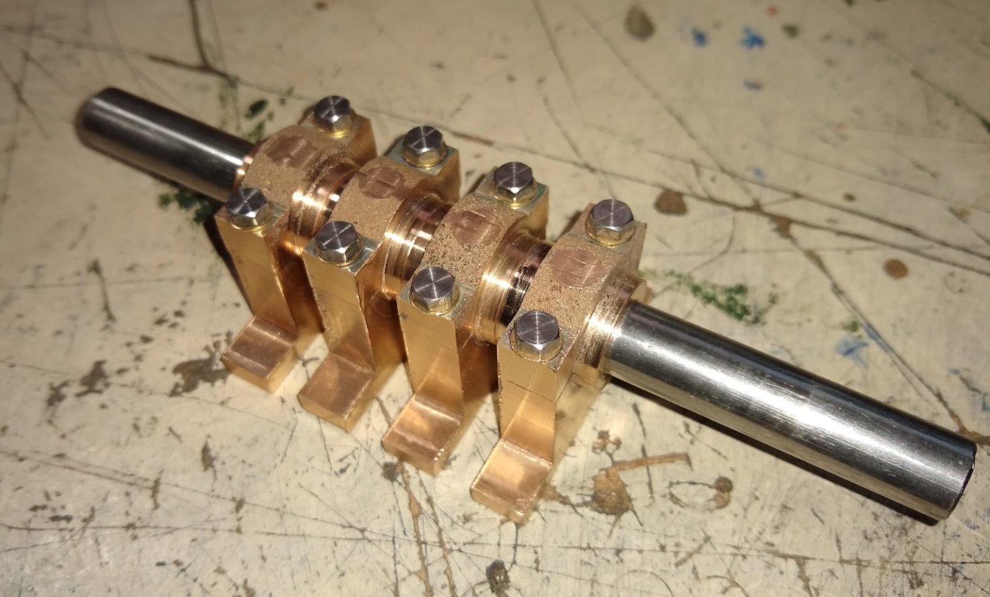
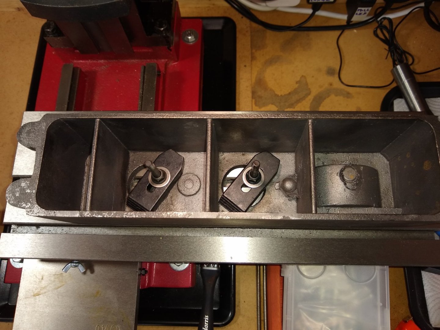
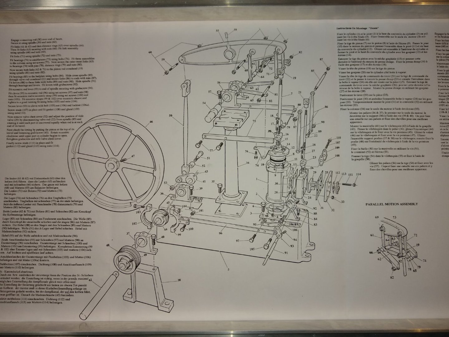
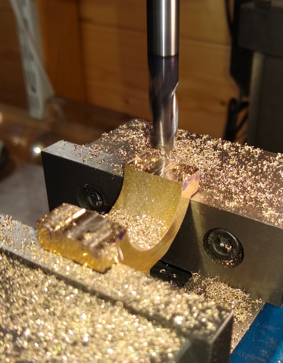
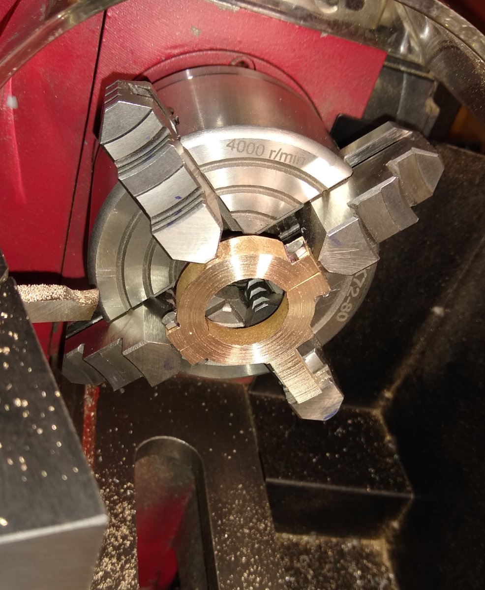
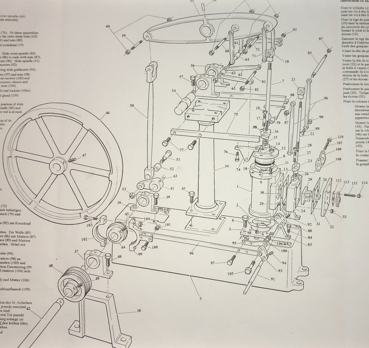
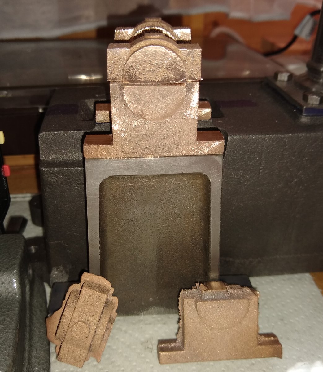
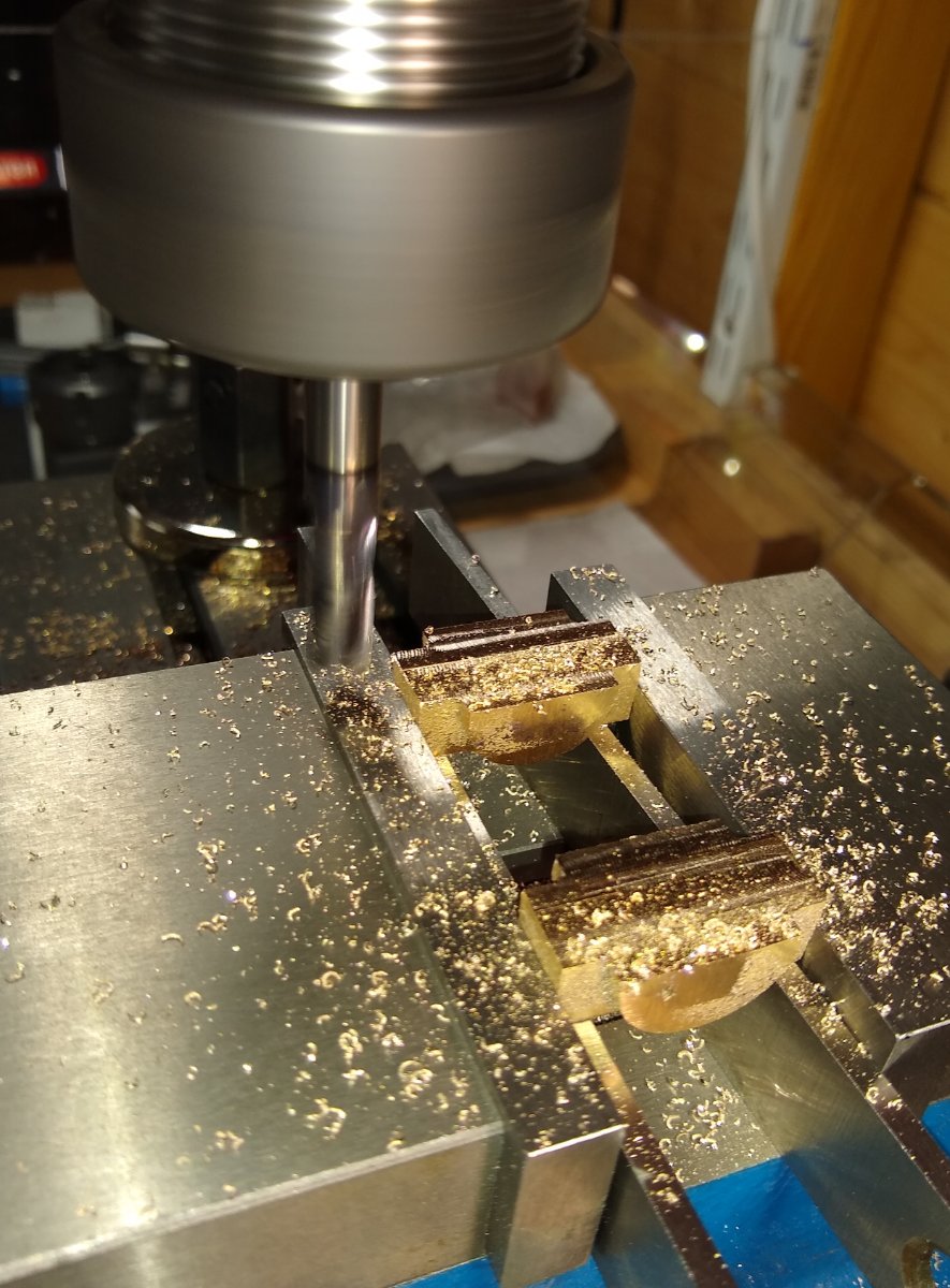
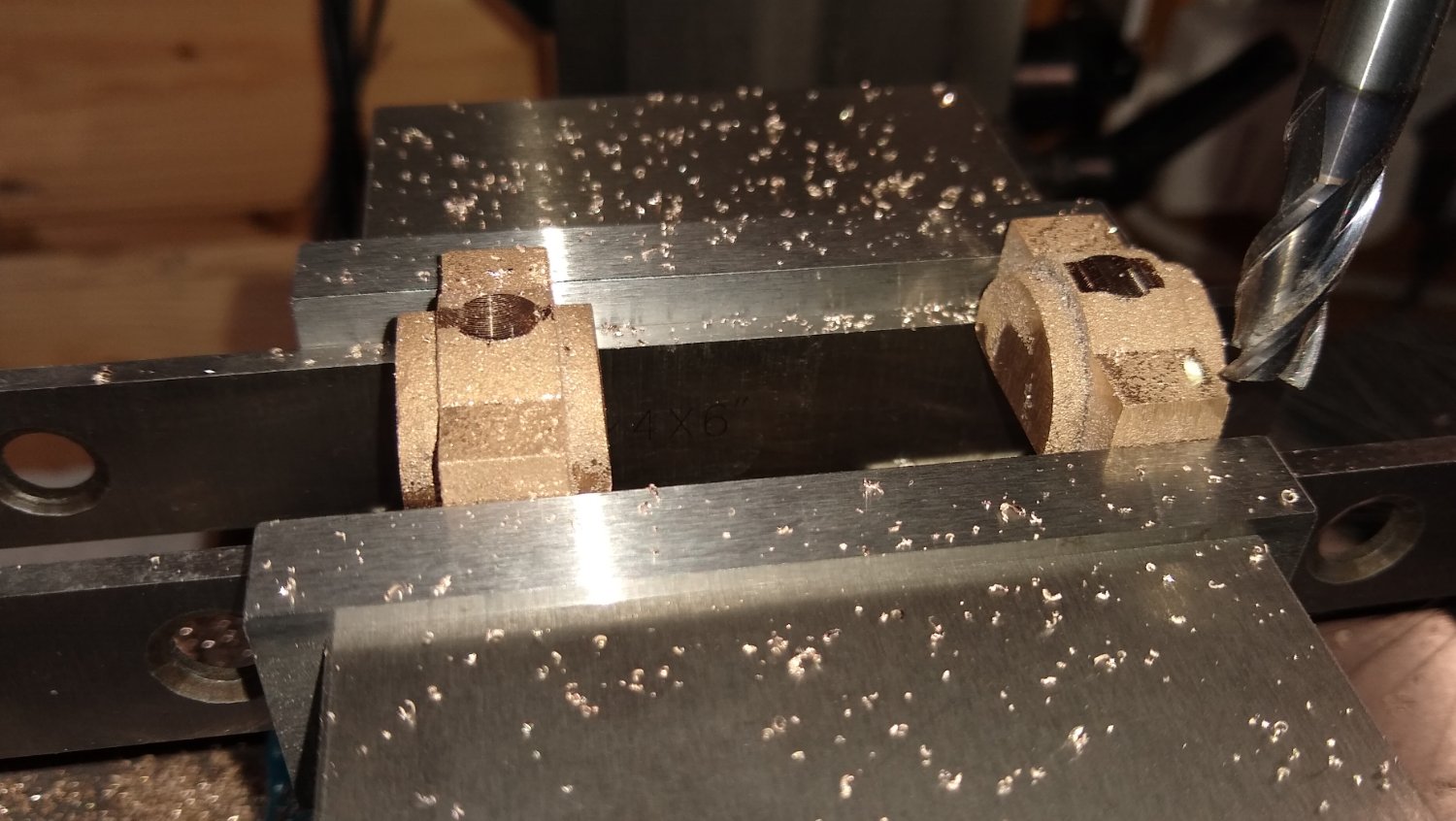
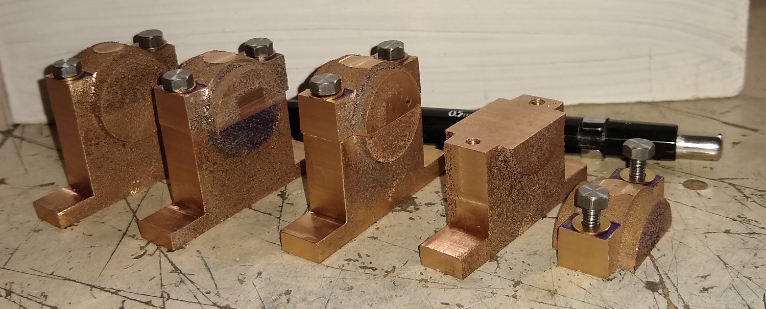
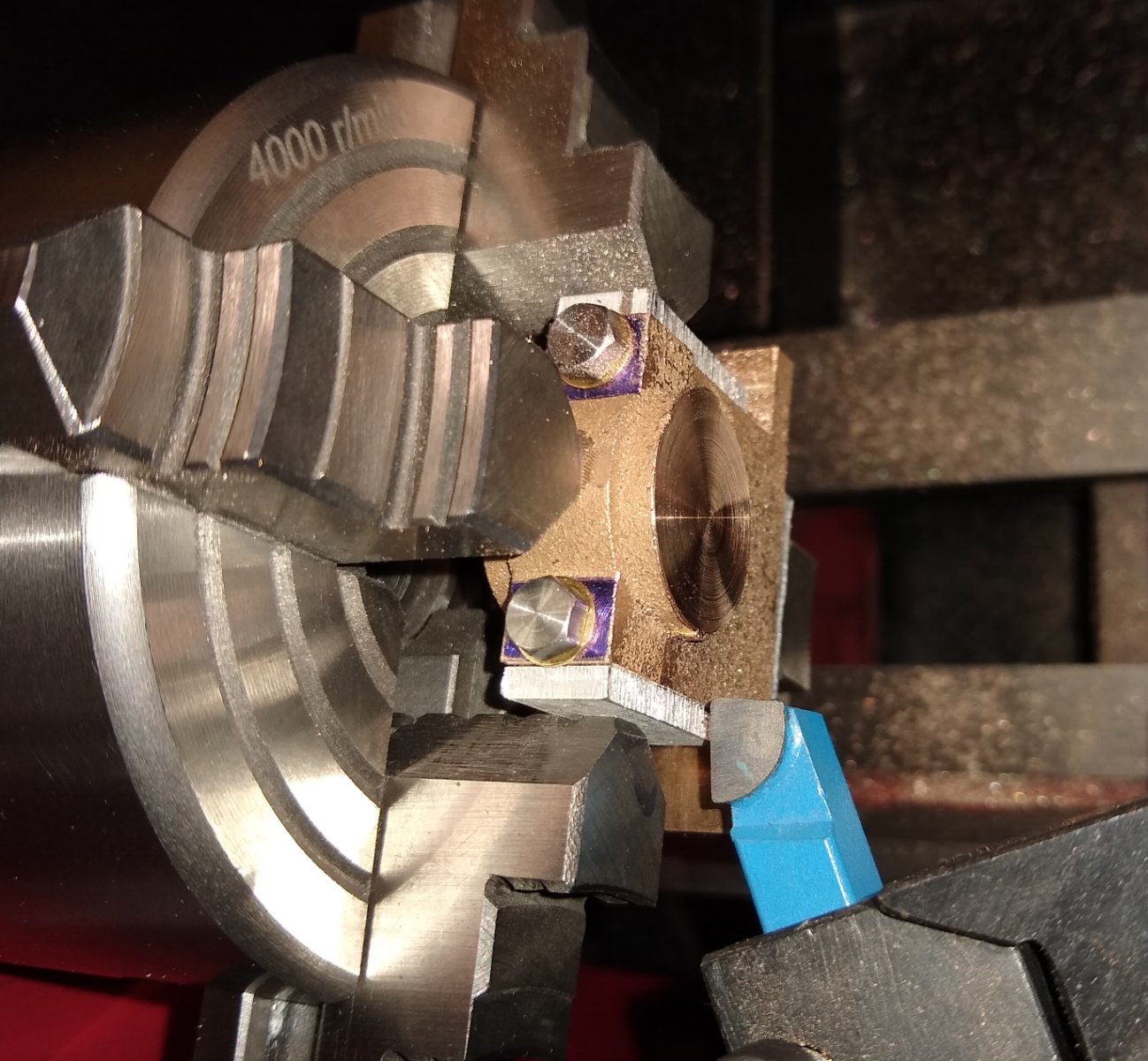
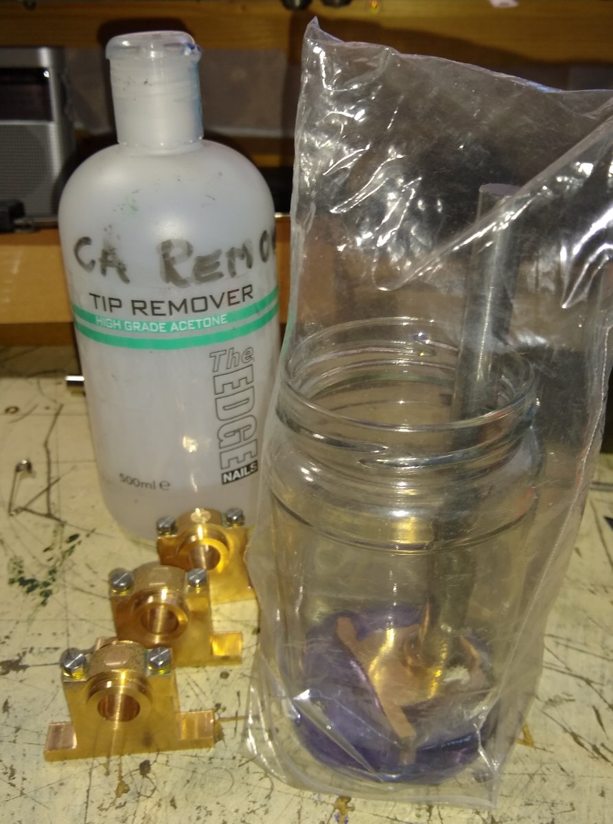
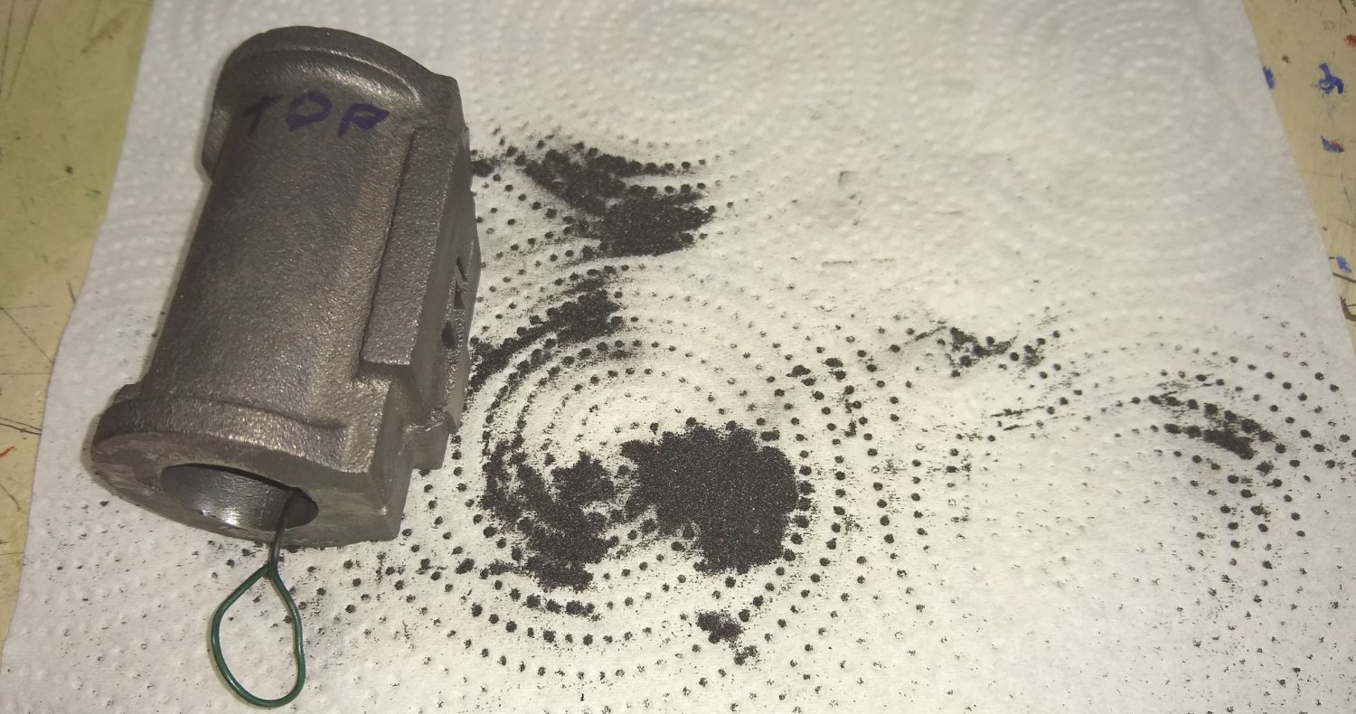
Hi all, Today I'm going to focus on the three sets of main bearings in the Beam engine, seen below in the exploded view ie the Crankshaft bearings (37 - bottom left), Beam bearings (56 - top middle) and the Watt linkage bearings (74 - middle right). In the real world, the Crankshaft bearings support great weights and experience constant rotation, so need to be tough, accurately made and have low friction. The Beam and Watts linkage bearings don't experience the same weights and experience oscillating part-rotational motion, meaning their wear pattern will be different from the Crankshaft bearings. The Crankshaft and beam bearings still need a lot of lubricating oil to prevent metal to metal contact and lower friction. And, I imagine, the oil also helps dissipate heat. I'm not sure if the Watts linkage bearings used oil reservoirs or relied on being made of a different material from the steel pivot shaft, say, Phosphor Bronze - more reading required and any advice welcome. Firstly, the Crankshaft/Beam bearings, shown below. They arrive from Stuart models as two-part brass castings . Earlier versions from Stuart seem to have been one-part castings. There are a number of faces that need cleaning up on the mill and lathe and the Crankshaft hole needs boring. Cleaning up one half of the mating Crankshaft/Beam bearing faces in the mill. Generally, I tried to machine the bearings in pairs to ensure they were dimensionally the same. They were spaced apart in the vice to allow even vice clamping forces, and are sitting on a pair of parallels. Below, the 'other side' of the bearing mating faces being milled. This time sitting on a single parallel that covered the gap in the base of the vice. It's always a puzzle as to what the optimum sequence of machining actions are eg the bearings underside had only been filed flat but my plan was to use the bored hole (later to be done on the lathe) as the datum for cleaning up the bearing feet. Below, cleaning up the sides of the bearing feet, again in pairs. And creating flats for the drilled and tapped holes that the oil reservoirs would screw in to. The Crankshaft/Beam bearings now ready to have the two halves joined by bolts. And here they are, ready to march off to the lathe. The bolts are 2BA (British Association) - I later replaced them with similar 2BA bolts but with smaller hexagonal heads that were more in keeping with the scale of the model. Below, positioning and gripping the bearings in the lathe's 4 jaw chuck was a bit tricky - there wasn't much to grip on, they needed to be axially correct for the Crankshaft/Beam bore and also had to be square to the chuck. The black thing is a threading attachment that happened to already be fitted to the tailstock and was called in to service to help achieve squareness of the part. Cutting the first surface on the lathe. The Stuart models part list does say the bearings are made of brass, but these parts have more of a Phosphor Bronze'y look to them, in my mind? I thought I'd photographed the boring of the bearings, but can't put my hands on the pics. I needed to buy a smaller boring bar than the one I had and that went fine. I used the (already made) Crank shaft as a gauge for the hole size. Below, the bearings were, one by one, Loctite'd to the Crankshaft for gripping in the lathe to face off the far side of the bearings. To break the Loctite bond I dipped the assembly in Acetone for about 5 mins - that worked fine. The four Crankshaft/Beam bearings sitting on the crankshaft ready for the next machining stage. Back to the mill. I used the crankshaft bore as a datum for machining the feet of the bearing to the same distance to the centre of the bore. Fortunately the vice was able to grip the bodies of the bearing without too much issue...I think I had to pack out a couple of them with a bit of paper. The Crankshaft os supported on V blocks sitting on 1-2-3 blocks. And now the Watts linkage bearings. They arrived as an extruded length of brass that needed drilling and cutting to width. The Watts bearing material centred in the 4 jaw. That went fine. I then tentatively parted off the two bearings whilst still held in the lathe, again that was OK...it it had been Mild Steel rather than brass I may have considered a different method eg saw to length and clean the sawn face up on the mill. Finally, a view of the bearings installed. The Crankshaft and Beam bearings proved to work fine - their shafts etc were already made, but the Watts linkage had to wait till their links were made. Also seen in this view are the machined Flywheel and partially-machined central support column, both of which I will add posts on in the near future. Regards, Richard Edit: I forgot that the Valve Linkage bearings (83 -bottom right of exploded view) were also made alongside the Watts Linkage bearings. So there were 4 pairs of bearings made in total.


- 72 replies
-
- 16
-
-
-
James, My initial post wasn't a 'complaint' .... it was more of a detailed heads-up for future reference for MSW Admin. Apologies if it was seen as such. As always, I think MSW is an amazing safe harbour - thank you. Regarding alerting folks (eg me) who refuse to allow 'social media' apps on their devices, how about an 'Announcements' heading on the NRG website ( https://thenrg.org/journal ) ...I don't think NRG use the same server as MSW since I'm sure I had a look on NRG for info when MSW was down. Regards, Richard
-
Roger, Yes, I did know of the power equation but I'll admit I wouldn't have recalled it easily since it donkey's years since I used it ;-). Fascinating that the diameter was the one variable that could be enlarged. I take it weight wasn't an issue and didn't affect the Centre of Gravity....I guess they placed the engine down the centre line. I did see a picture of a railway engine boiler explosion the other month .... it was dramatic....the cylinder burst open and many, many lengths of narrow diameter piping all over the place, and sadly some lost of life. I'm (so far) only running my steam engines on compressed air.... primarily because I don't want the risk of boiler explosion or fire near me (or anyone). Richard
-
I have been following this YouTube channel for a while Yes, I've been following Blondiehacks for a couple of years. She's very good at explaining things. That current steam engine build of her's is quite large and needs a bigger lathe than I have. But it is fascinating to see it coming together. Richard
-
Steam Trawler 'Huddersfield Town' off the Faroe Islands Tremendous. That sea colour is amazing. Richard
-
Roger, Thanks for that. The steamers on the Great Lakes are something that has recently appeared on my radar and is a fascinating subject. I need to read up on it. Six foot diameter is some size .... but no doubt designed to match the requirements. A few months back I bought 'When Rails meet the Sea' by Michael Krieger ...not got round to reading it yet but looking forward to it. It focuses on the American port cities 1830-1960. Richard
-
Egilman, Agreed. But since these are castings with little or no regular sufaces to locate on to I went for the mill first, to give me a square face to grip on once it was in the lathe. And since the batch size is only 'One Off' mating parts can be fettled to suit 😉 These engines are interesting and, usually, relaxing projects. One of my favourite scratch builds is this one here .... https://www.modelenginemaker.com/index.php/topic,10250.0.html It's a real tour de force requiring skill, perseverance and knowledge. Most of it was done on Sherline equipment ...the forum thread is over 140 pages long so that gives some idea of the complexity involved. regards, Richard
-
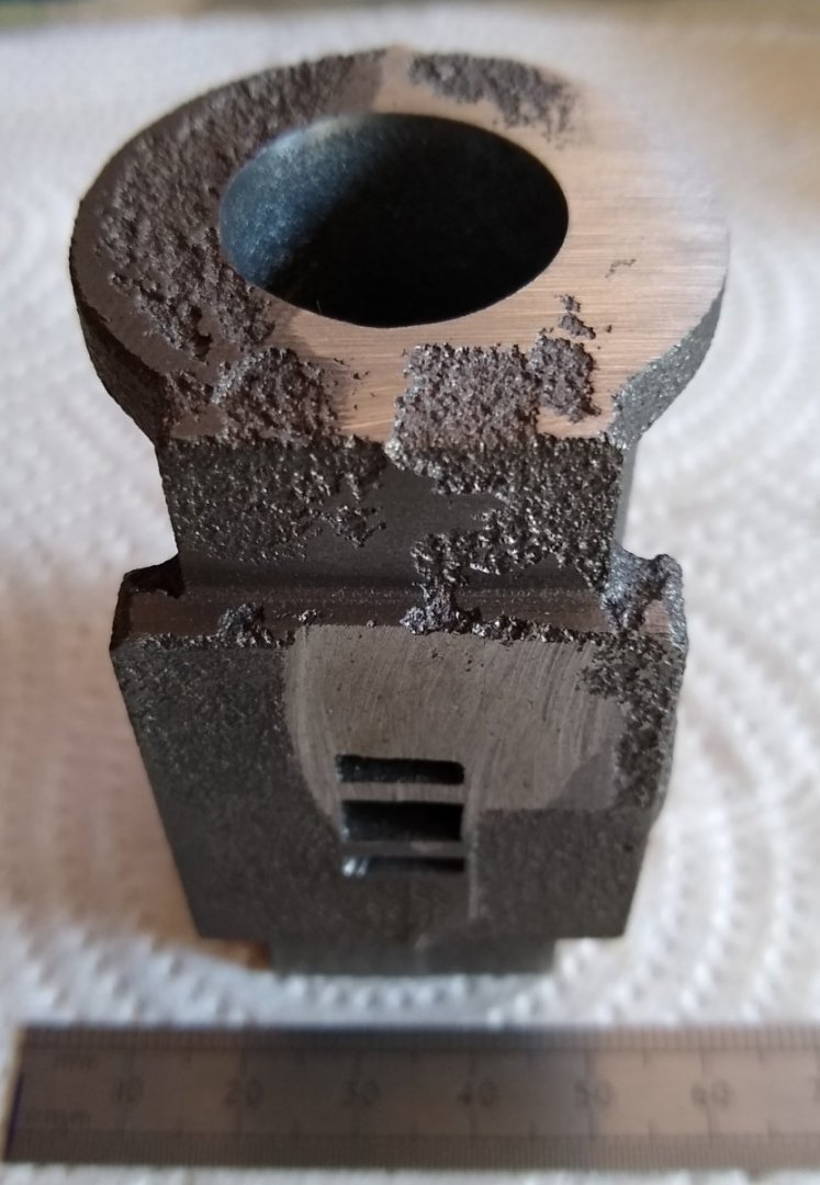
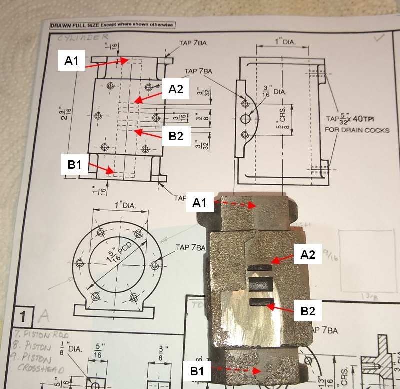
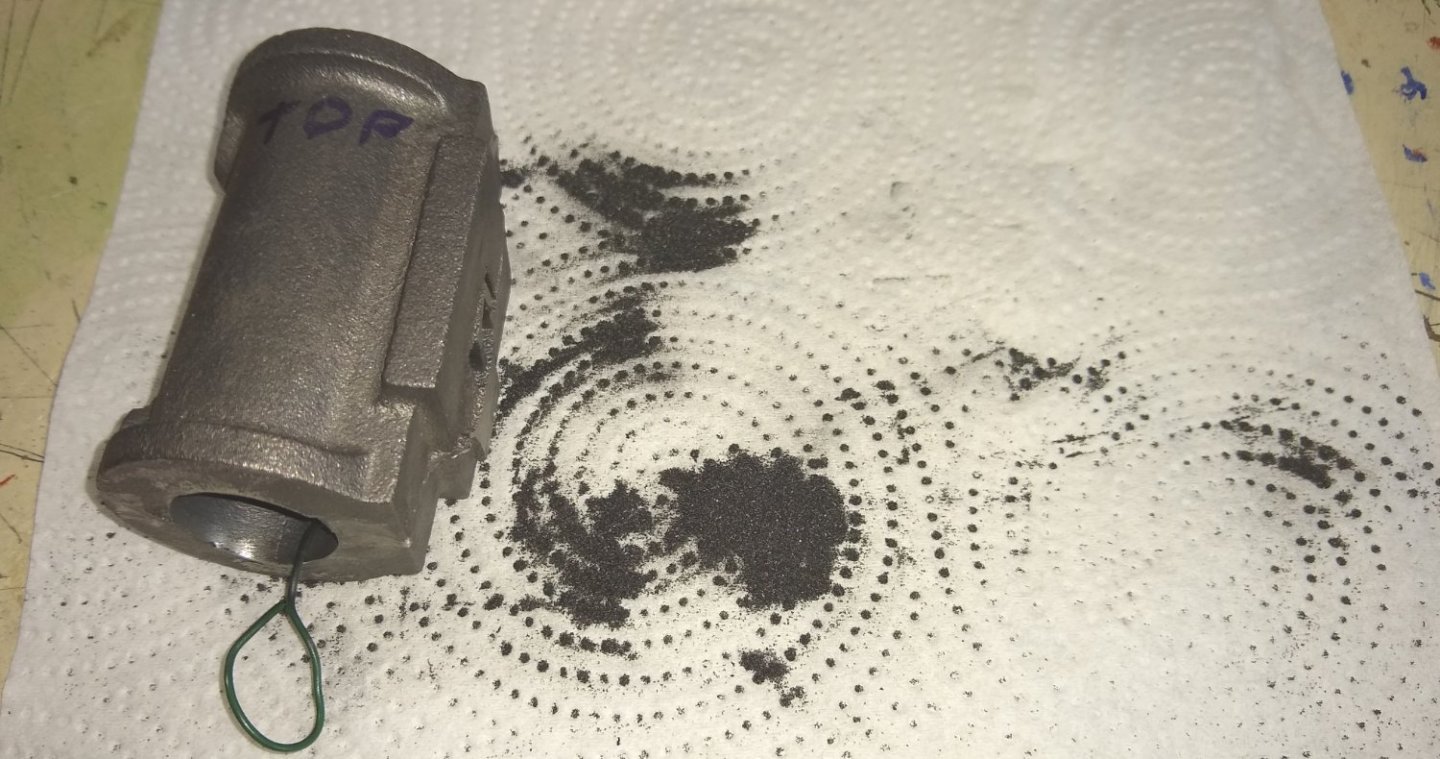
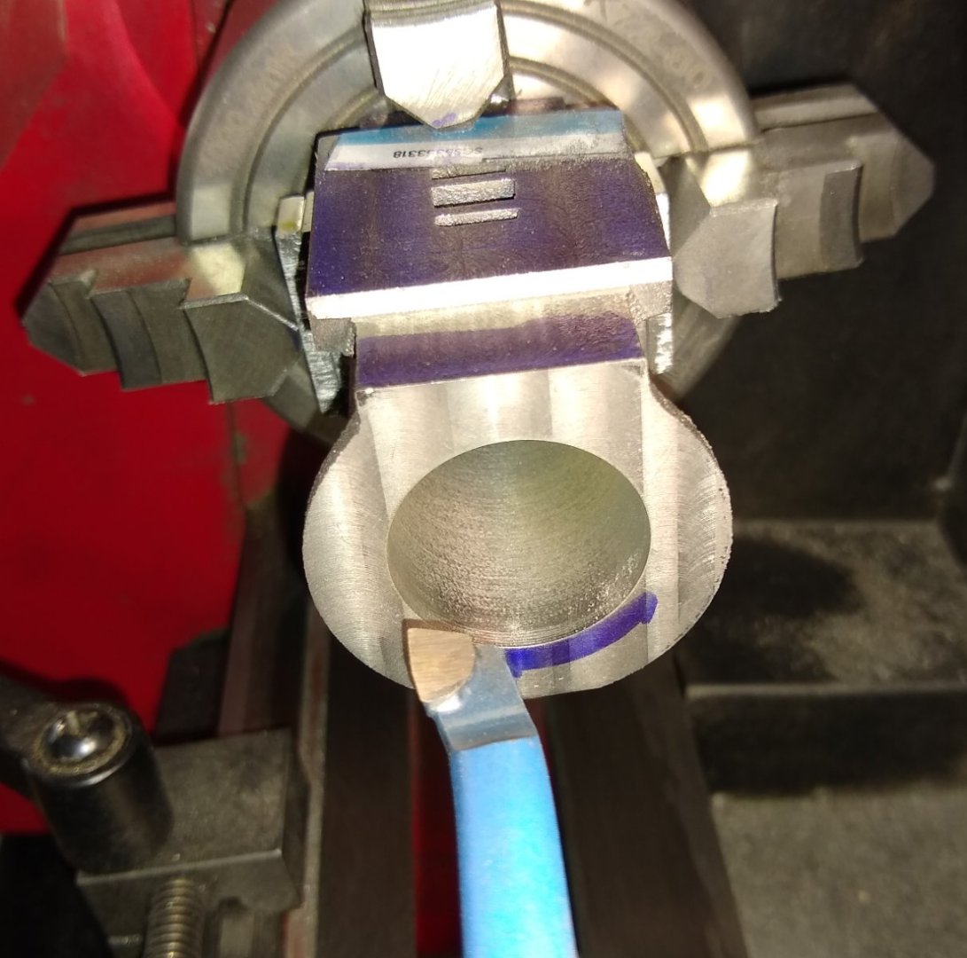
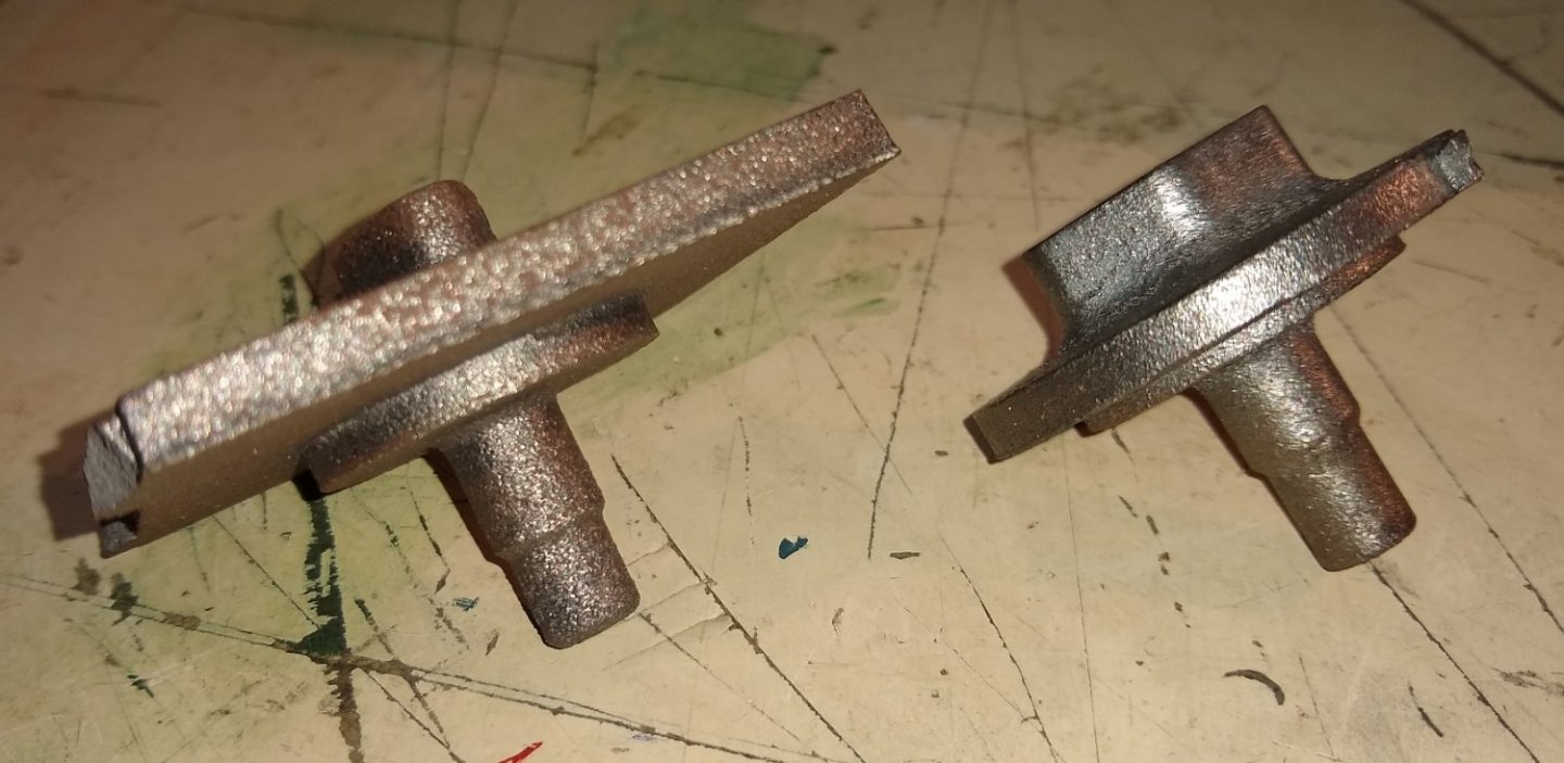
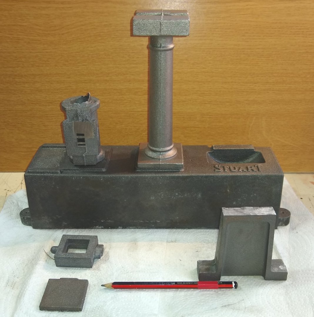
Hi all, Thanks for the Likes .... and Egilman... yes, materials are continually improving although I suspect that Stuart Models, who came in to existence in the very late 1800s, may still be using using some of their original casting equipments and methods. OK, that's a slight exaggeration but Stuart do hold on to their practices for a long time, which probably isn't a bad thing. Today I'll focus on aspects of the Cylinder, that part of the engine where the energy of the steam is turned in to work. Below is the exploded diagram showing the Cylinder...Part (1) over on the right side. As can be seen from above, the Cylinder has a Piston inside that moves up and down courtesy of the Valve (29) alternatively applying steam pressure to the Piston's (8) top and bottom surfaces. The power chain is.... Piston Rod end> Beam end at the right> Beam end at the left> Connecting Rod> Crank> Crank Shaft> Output Pulley. The Flywheel (46) stores energy, and also helps smooth out the 'explosive' outputs from the steam entering the Cylinder ends. Below, the cast Cylinder as it arrives in the box. Stuart Models give the cast parts a quick grind at their factory to remove the more obvious flash from the casting process. However, in this case the grinding went a bit too deep on the Valve face meaning there wasn't sufficient material left to meet the final dimensions. Stuart models happily replaced the part in a few days. Below is the Detail drawing of the Cylinder. You can see on the rectangular front face there are ports marked A2 and B2 ...this is where the Valve lets the steam enter the Cylinder. The steam works it way to either end of the Cylinder (A1 and B1) where it emerges on to the piston face. Above, there are three ports in the centre of the valve face outlined in dotted lines on the drawing. From top to bottom - - A2, feeds steam to Cylinder top, - Exhaust port allows used steam to exit, - B2, feeds steam to Cylinder bottom. Below, there was a lot of black casting sand left in the Cylinder ater the part had been cast - enough to firmly block off the connections between A2/A1 and B2/B1. It took about 30 mins to wiggle it all out with some garden wire. Below, the amount of sand removed. I was quite impressed by how much had crammed itself in there! Below, machining the Cylinder in the mill. The Wixey digital angle gauge proved to be a useful tool throughout this project. Below, machining the valve face smooth and flat. I later filed the three openings approximately to the sizes the drawing requested...I'm wondering now if I should have actually used a small diameter milling cutter to more accurately form those openings?...maybe, but from what I recall the openings weren't exactly in the positions the drawing showed. Now taking the Cylinder to the lathe to do some boring work ie open out the hole that the Piston will side up and down in. I wasn't 100% sure whether to bore out this hole first on the lathe and use it as a reference before milling the cylinder faces, or the other way around ie mill or lathe work first? - I eventually decided on 'mill first'. With a bit of careful clocking on the lathe using the 4 jaw chuck I got the Cylinder positioned good enough for a concentric bore. Below, finishing off the bore. It ended up about 10 thou" (0.25mm) undersize...enough spare material, should I later decide to do some honing on it. Below, are the two end caps that seal off the Cylinder (Bottom cap left, top cap right). Not the easiest of things to hold in a lathe....fortunately Stuart leaves a casting shaft protruding for gripping in the lathe. These shafts should be turned to a smooth finish before being turned around and held in the lathe chuck jaws. Setting up the Cap shafts for turning by using a drill chuck to hold the Cap square whilst the 4 Jaw was adjusted to grip the Cap. The already shiny perimeter of the Cap was done on a grinding wheel (to remove the hard cast outer layer) so is not that accurate, yet. It will be once the shaft is held in the 3 jaw chuck. Finally, the Piston (mounted on the Piston Rod).... and it's 'Piston Ring' aka O RingWhen the O Ring was originally fitted to the Piston it sat about 40 thou (1mm) proud of the Piston, which was of no use. I investigated alternative, small CSA O Rings and also tried some of the supplied Gland Packing material ...but no joy...none of them was going to give a reasonable piston seal/sliding action in the Cylinder. Note: The piston was already a sliding fit in the Cylinder so could probably have worked OK without any O ring. I eventually hit upon the idea of using Emery cloth to grind away about half of the O Ring till it was almost flush with the Piston. And after a few trial fits and a bit of lubricant this worked a treat 🙂 Well, that's it for today. Next up should be the Valve apparatus. Regards, Richard

.thumb.jpg.2b2457b3812aa2b2f876e5814d7ecda3.jpg)


- 72 replies
-
- 12
-
-
-
MSW was down for me in the UK - appx 10.30am - 4.30pm. Then it came back up for about 90 mins then down again, and has now resurfaced this morning at 10.15 am. Below is the error message that popped up after 30 secs or so. The 'new posts' all have a date stamp of '17 hours ago'. It seems I lost a Post I made yesterday afternoon in the 90 min window, but no big deal. Richard

-
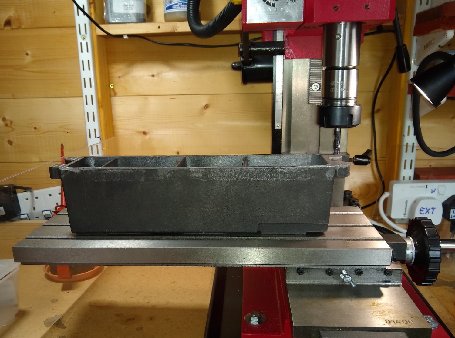
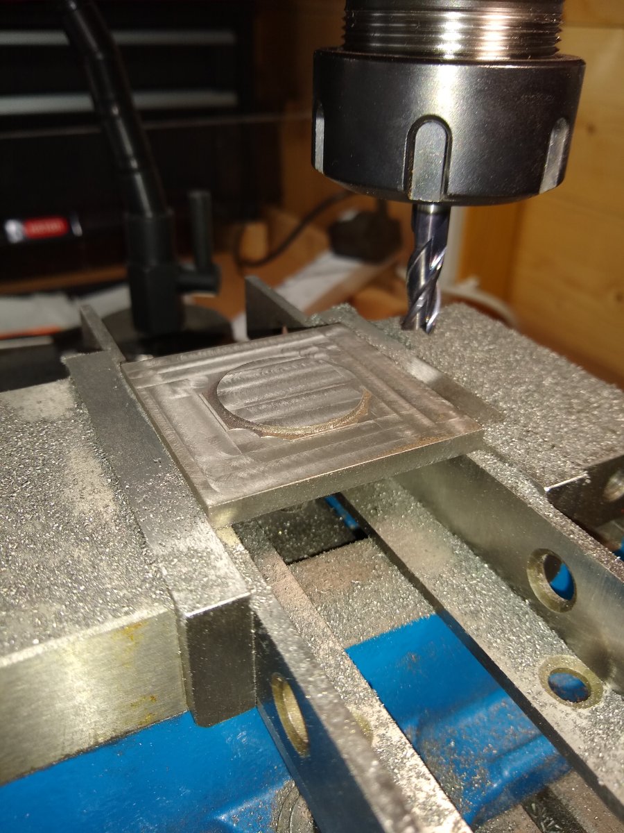
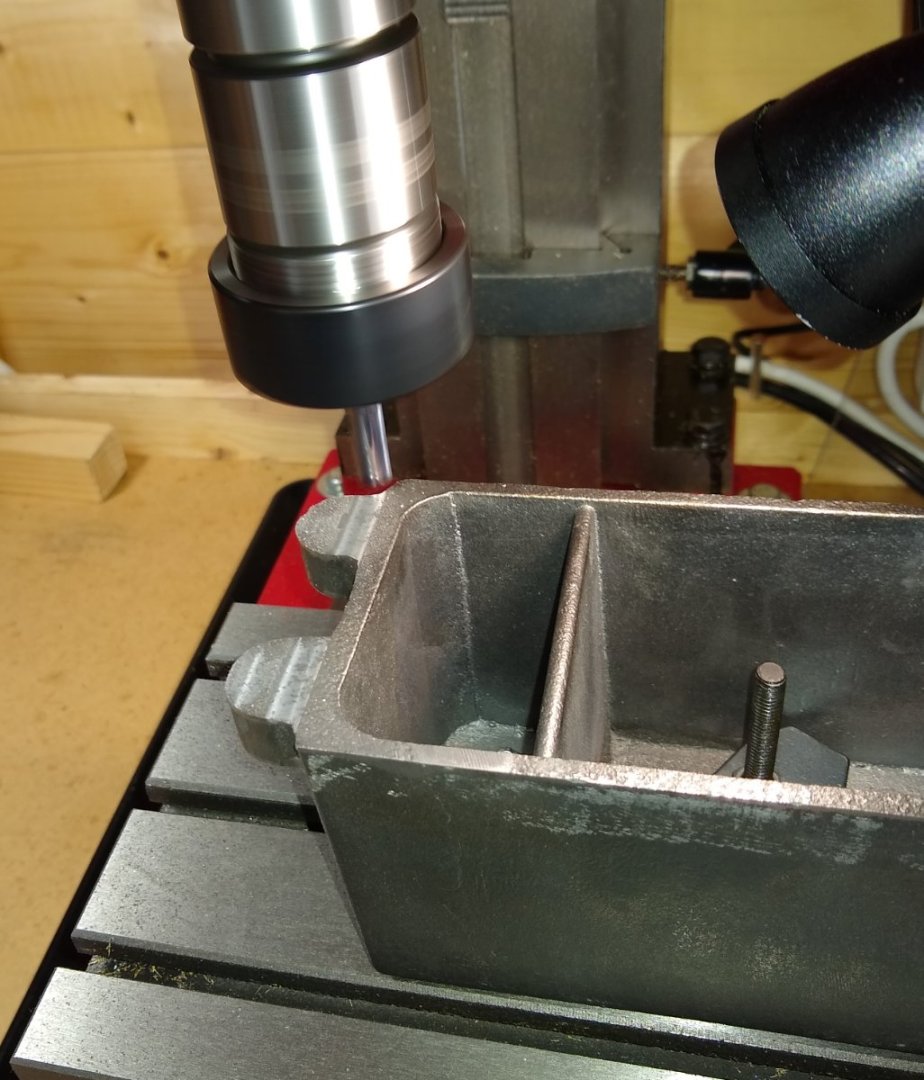
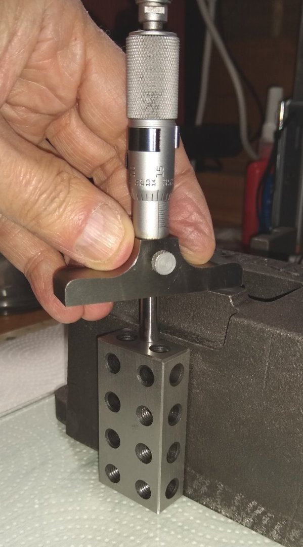
The first part to be machined was the engine's base, officially known as the 'Bedplate'. Below, I cleaned up the Bedplate by filing off casting flash before presenting it to my SX2P mill. The table of the mill measures 15 3/4" (400 mm) x 5 3/4" (145 mm) which meant it was 'just' large enough to hold the Bedplate. I think I used a 3 flute (diameter 8mm or 10mm?) carbide cutter for most of the machining on the Bedplate. Since cast iron can exhibit almost diamond hard surfaces if cooled too quickly, carbide tooling can sometimes be necessary .... High Speed Steel would blunt in a second. I don't recall any hard spots on the Bedplate but generally you never know they are there till you hit them. Below, clamping the Bedplate to the mill table. The four mounting lugs plus the underside of the Bedplate were skimmed level. Below, and flipping the Bedplate over (onto it's now-flat-base, I machined the mounting pads for Linkage Bearings, Cylinder, Column and Flywheel Bearing. Whilst I had the Bedplate on the mill I also drilled and tapped the holes (not shown) in the pads. As you can see, the clamps at both ends just fit on the length of the mill table. Below, checking the height of one of the pads during the milling operation with a 2nd hand Moore & Wright 1" depth gauge and a 1-2-3 block. I bought the depth gauge of eBay in the Spring, and once it was cleaned up it was as good as new. Note: The assembly isn't sitting on a paper towel 😉 ... it's sitting on a 1/4" thick 'Surface Plate' made of float glass. Below, the cast iron Cylinder Bottom Cover being machined on the mill. The Cover attaches the Cylinder to the Bedplate, and it did have some hard spots around the corners where it would have cooled quickest. OK, that'll do me for today. It's been a while since I did any Posting on the Forum so I feel a bit rusty ...apologies for any glitches. Regards, Richard


- 72 replies
-
- 14
-
-

-
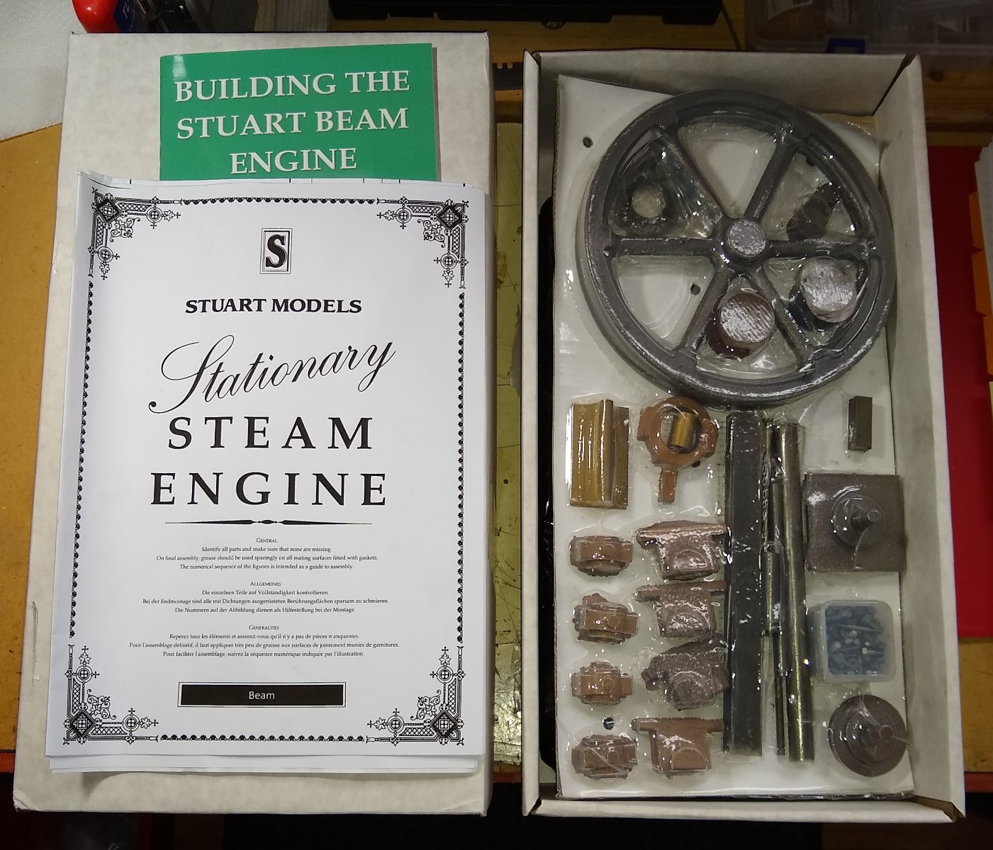
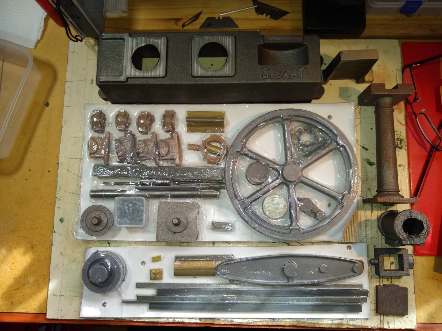
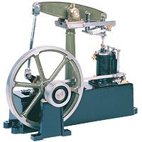
Hi all, This is a record of my Stuart Beam engine build. The suppled kit consists of cast iron castings, various sizes of brass and mild steel bar, fixings etc. It is available here - https://www.stuartmodels.com/product/stuart-beam-unmachined/ Rather than try to capture every step in the manufacture I'll concentrate on some of the more interesting/challenging aspects. But firstly, a bit of background on 'beam engines'. They had been about for quite a while before James Watt came along with his 1776 patent to improve the efficiency of the engine which turned it in to a more practical and cost-effective way of supplying power to various industries ( https://en.wikipedia.org/wiki/Beam_engine ) Watt also designed the Beam engine's Watt Linkage which allowed the vertical motion of the piston rod end to connect to the beam end (which describes an arc). One of the main applications of Beam engines was to pump water eg help supply a town's population with water. Quite a few Beam engines have survived to this day - a great example is the Rotative Beam Steam Engine At Crossness - https://www.youtube.com/watch?v=Zlp1aG1VJRI These are very graceful but powerful, slow moving machines (typically 11 rpm). My model rotates slightly faster 😉 (And since no 'garage' collection is complete without a Beam engine, Jay Leno also has one ... https://www.youtube.com/watch?v=zoBWAE0win0ce ) Electric pumps eventually replaced these wonderful machines, since they required much less maintenance and less bodies to keep an eye on them (eg oiling all the metal to metal interfaces). So, on to my build. As with the Stuart 10V I bought the booklet that covers the engine build - it was OK but perhaps not as useful as the 10V booklet. The cardboard box this time was much larger and heavier. The contents are shown below. Above, there are two large sheets - Detail Drawing sheet for all the parts, plus a Build guide/Parts list/ Exploded diagram sheet. The actual parts arrive sealed on to two pieces of cardboard. Below, doing a head count of the parts. Below, six of the larger cast items. The very large base (Bedplate) turned out to be a tight fit on my milling machine, with just enough space left at the ends for clamping. Below, the brief build instructions alongside the exploded view. The Beam flywheel is 7" diameter, when finish machined - the 10V's flywheel was 3" diameter, so at times I did wonder if this time I needed a bigger workshop. Well, that's a brief introduction to my Beam ... I'll follow up shortly with a post covering the machining of the base and maybe some other stuff if time allows. Bye for now, Richard


- 72 replies
-
- 13
-
-
Thanks Phil. I really enjoyed building the 10V. I've now started the Beam Engine .... https://www.stuartmodels.com/product/stuart-beam-unmachined/ ...which is a step up and should see me through the summer .... and then I have the Governor set to add to it. HMS Flirt is still sitting on my desk half finished.... I really need to get started on the rigging etc but I don't feel ready for it at the moment. I guess initiative comes and goes in cycles 🙂. I do miss the daily 'forum chat' associated with a ship buld log so I hope to get back to Flirt in the not-too-distant future. Richard
-
Dan, No probs. Actually, now I have had a look at your blog I realise I have already been reading it :-) The dark wooden finish looks great and the darker rubbing strakes etc set it off very nicely. Richard
- 49 replies
-
- 1
-
-
- Lady Eleanor
- Vanguard Models
- (and 1 more)
-
Dan, The colouring I used was 'Rit Dye Powder - Cocoa Brown' ... eg https://www.amazon.co.uk/gp/product/B00AQ6ZGAM/ref=ppx_yo_dt_b_search_asin_title?ie=UTF8&psc=1 I probably spotted it being used on one of the previous Fifie builds, or perhaps Chris recommeded it in the manual. I think I diluted it a little. Do you have a Fifie build log we can look in on? Richard.
-
kit review 1:200 German Battleship Bismarck - Amati
Rik Thistle replied to James H's topic in REVIEWS: Model kits
James, What a model!. It's a bit too large for me, but never say no 😉 I think the Cost -v- Build Enjoyment ratio will be very good with this model. The detail in the pics is impressive, as are the technologies these ships carried eg two side launching aircraft. Are you actually planning to do a build of this Bismark or was this a Review only?.... with all the builds you have going on I can guess the answer. Regards, Richard PS: And thanks for the 50 min video link...that's earmarked for this evening's viewing. -
Richard, I had responded by mentioning Keith Appleton as a 'beginner who started 4 years ago....whoops... https://www.youtube.com/c/keithappleton/featured. Keith is actually a very experienced hand at building and fettling steam engines and anything but a beginner. He also builds model steam powered boats/ships, amongst many other activities. I had meant to point you towards Andrew Whale .... Learning Turning Metal - https://www.youtube.com/c/LearningTurningMetalbyAndrewWhale/videos. Here is Andrew's first video - Sieg SC3 mini-lathe unboxing - https://www.youtube.com/watch?v=KP1MzFsrSLE Richard


.jpg.207f3843f6a8b599bae8957dc5fbe2f1.jpg)
.jpg.4281aca4ee6e4ea45cf4d71b9258358f.jpg)


.jpg.ca33e863800fa15aa551e28bc5cd60fc.jpg)