HOLIDAY DONATION DRIVE - SUPPORT MSW - DO YOUR PART TO KEEP THIS GREAT FORUM GOING! (Only 44 donations so far out of 49,000 members - C'mon guys!)
×

Rik Thistle
-
Posts
864 -
Joined
-
Last visited
Content Type
Profiles
Forums
Gallery
Events
Everything posted by Rik Thistle
-
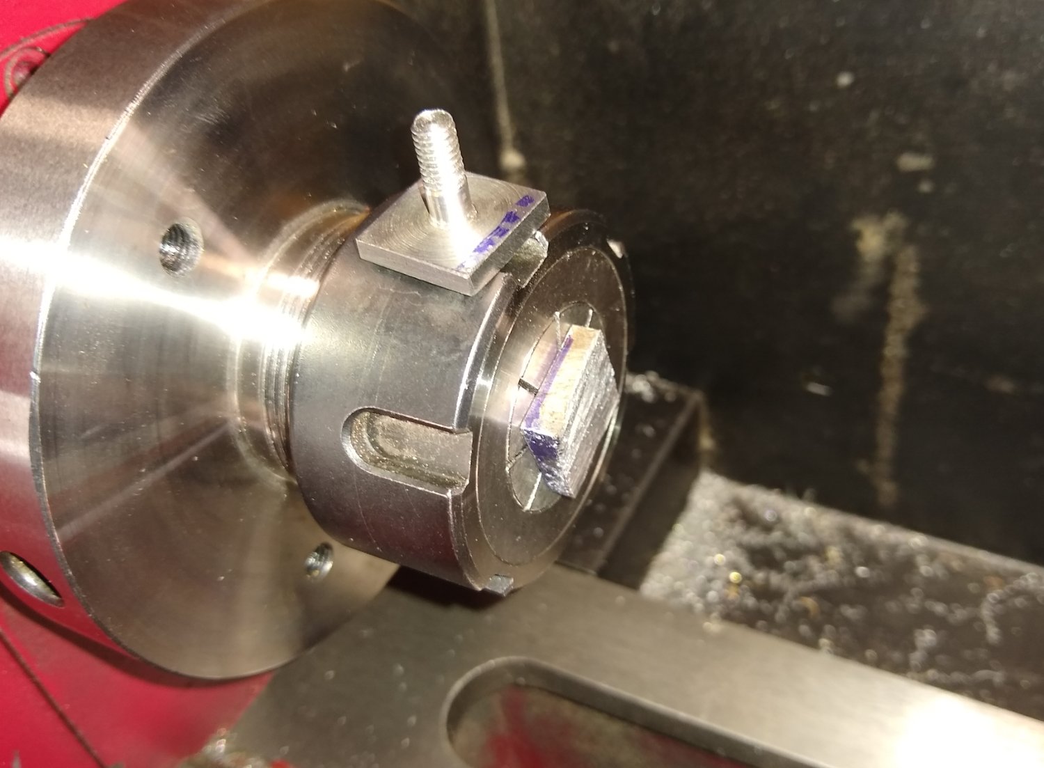
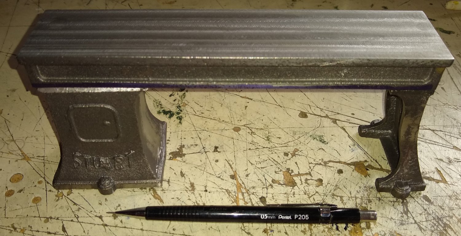
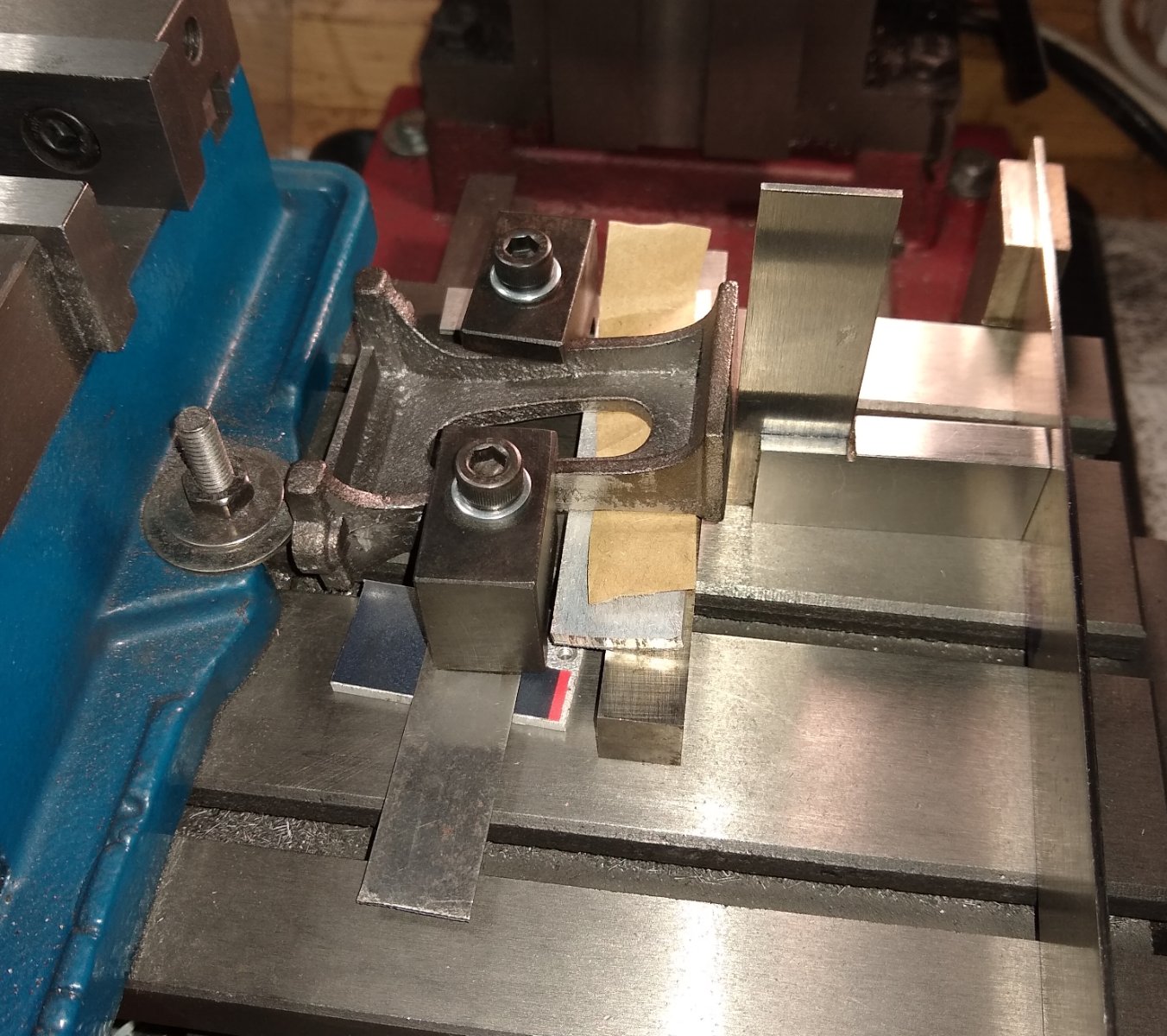
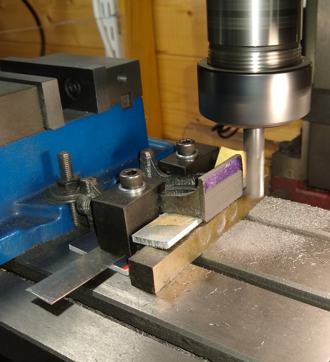
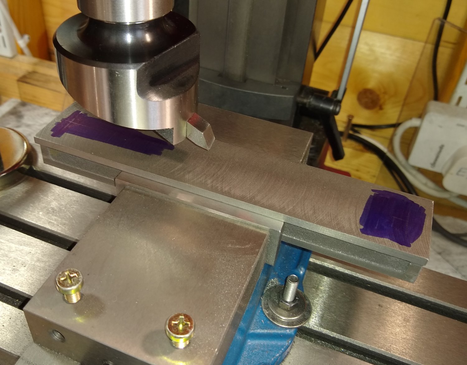
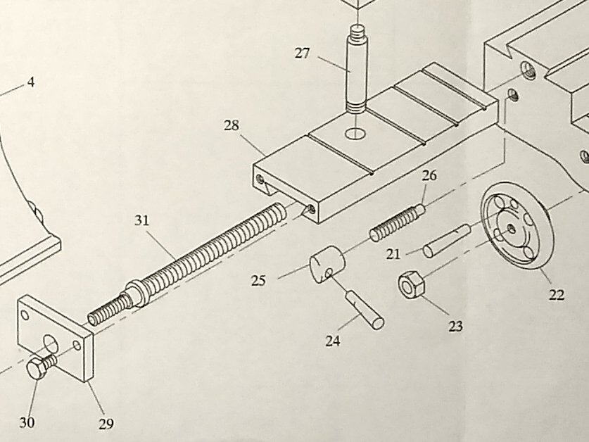
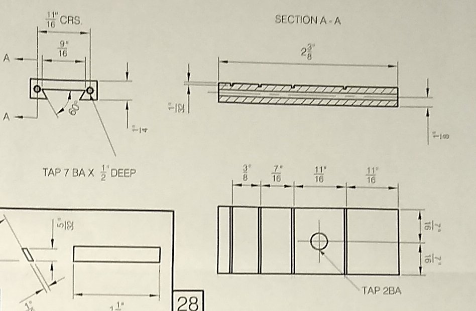
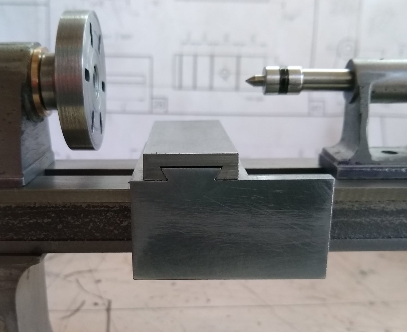
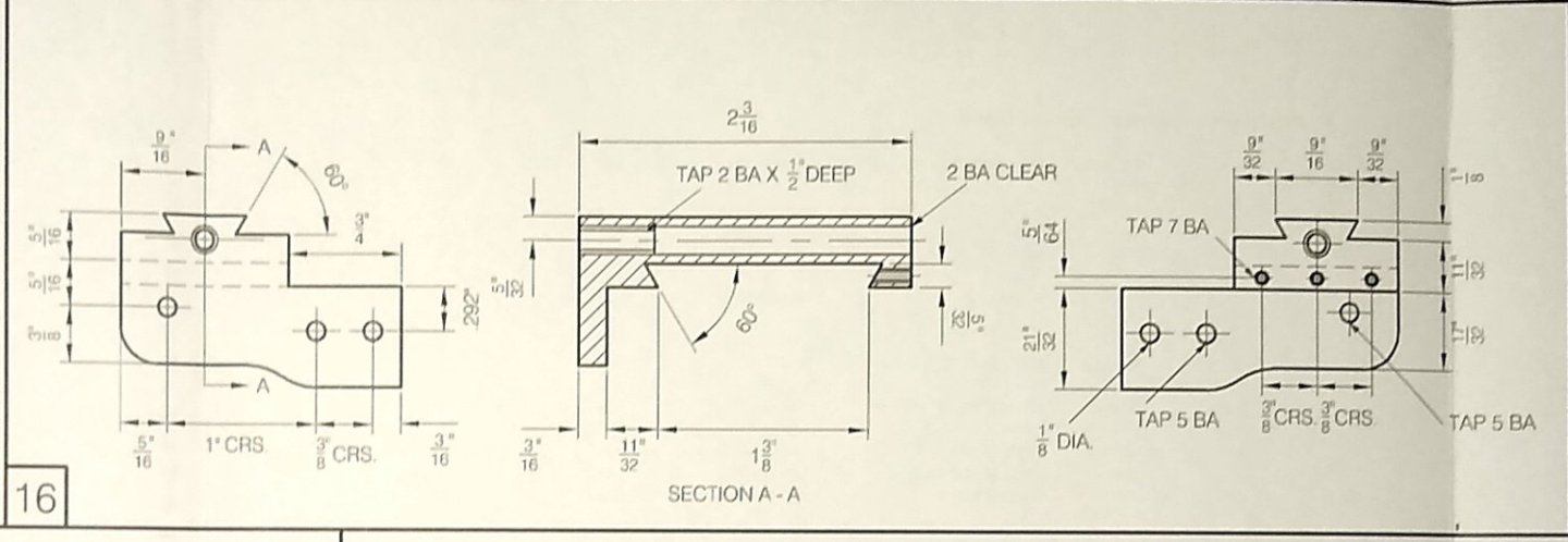
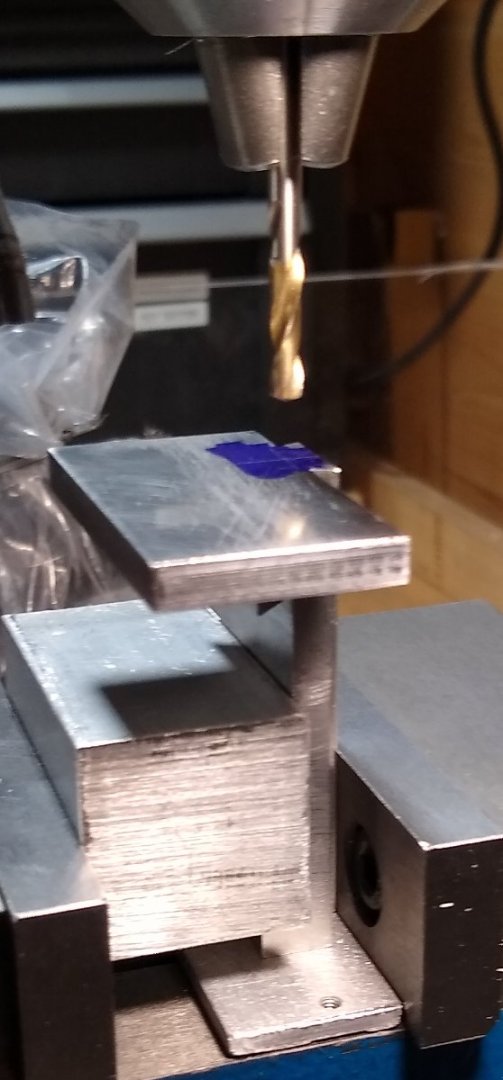
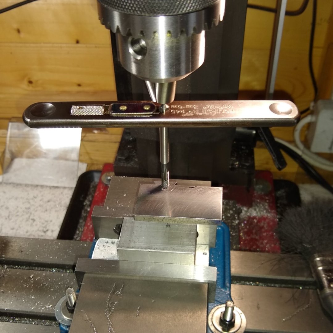
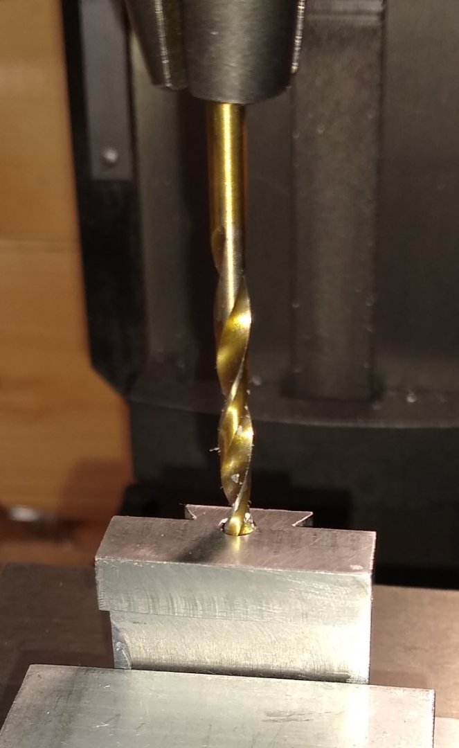
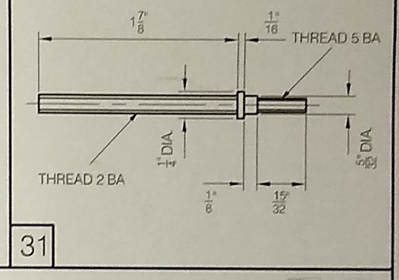
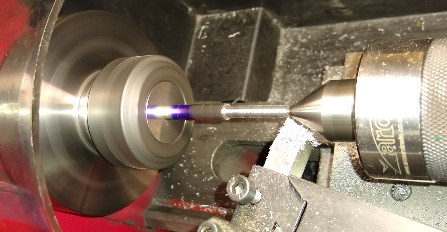
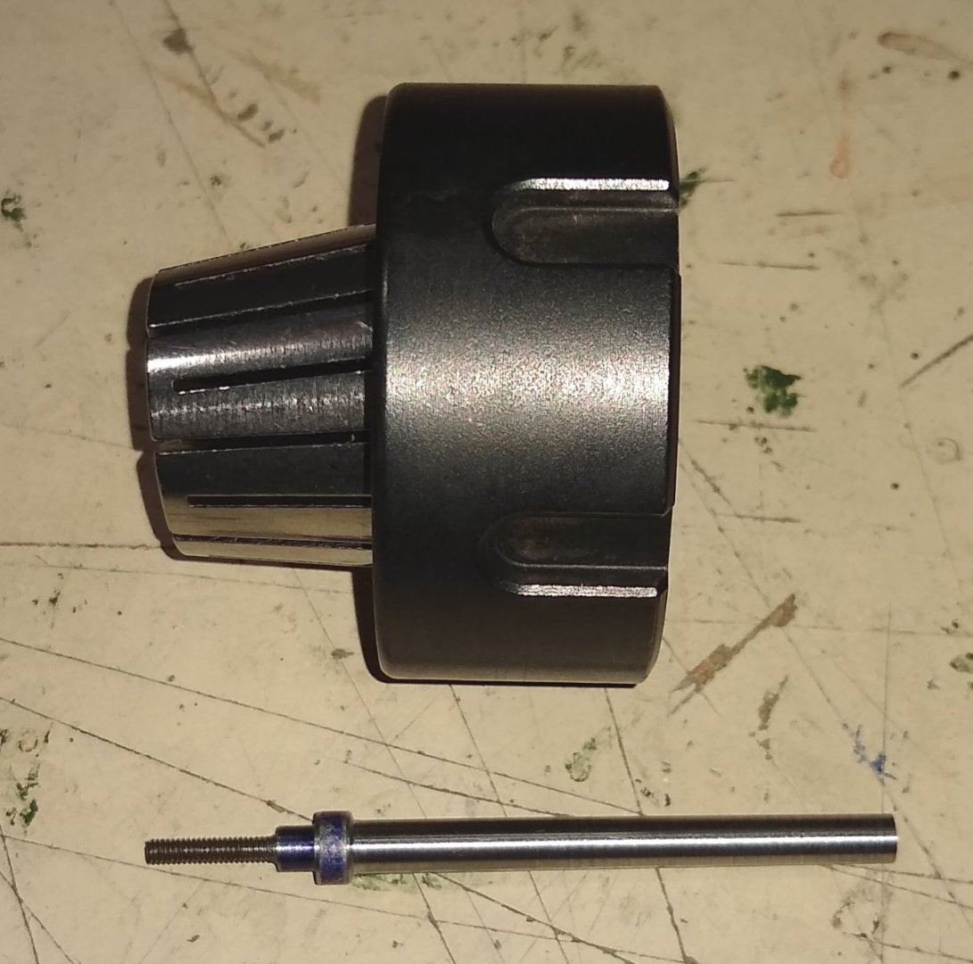
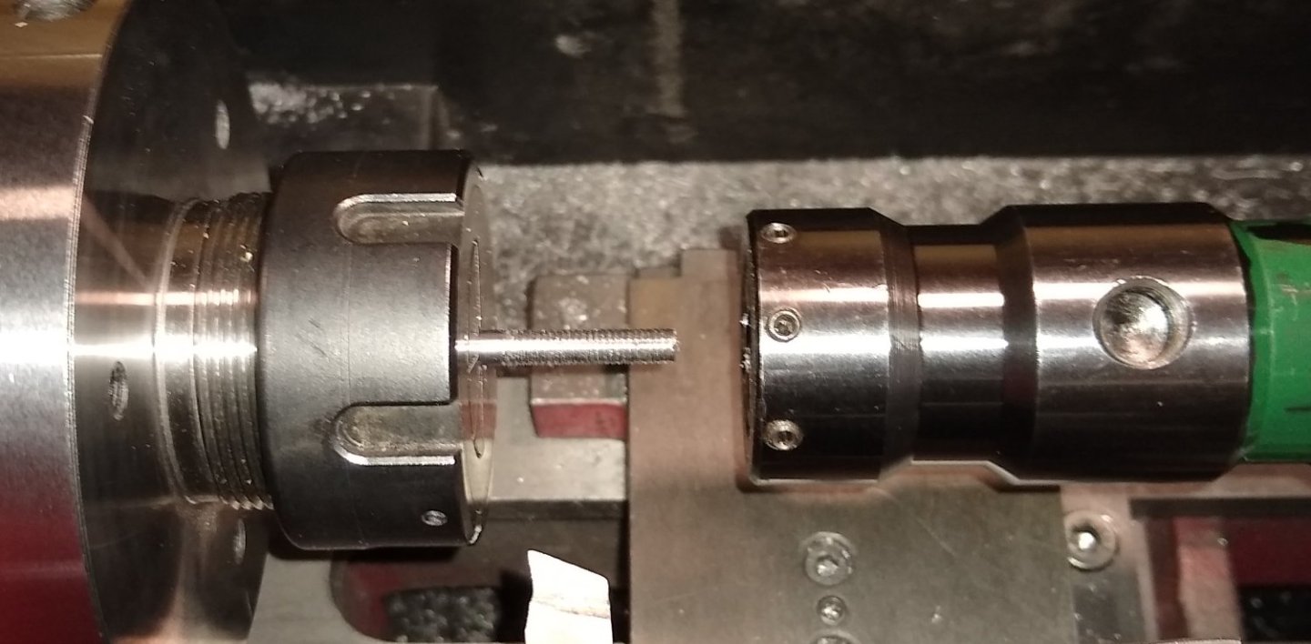
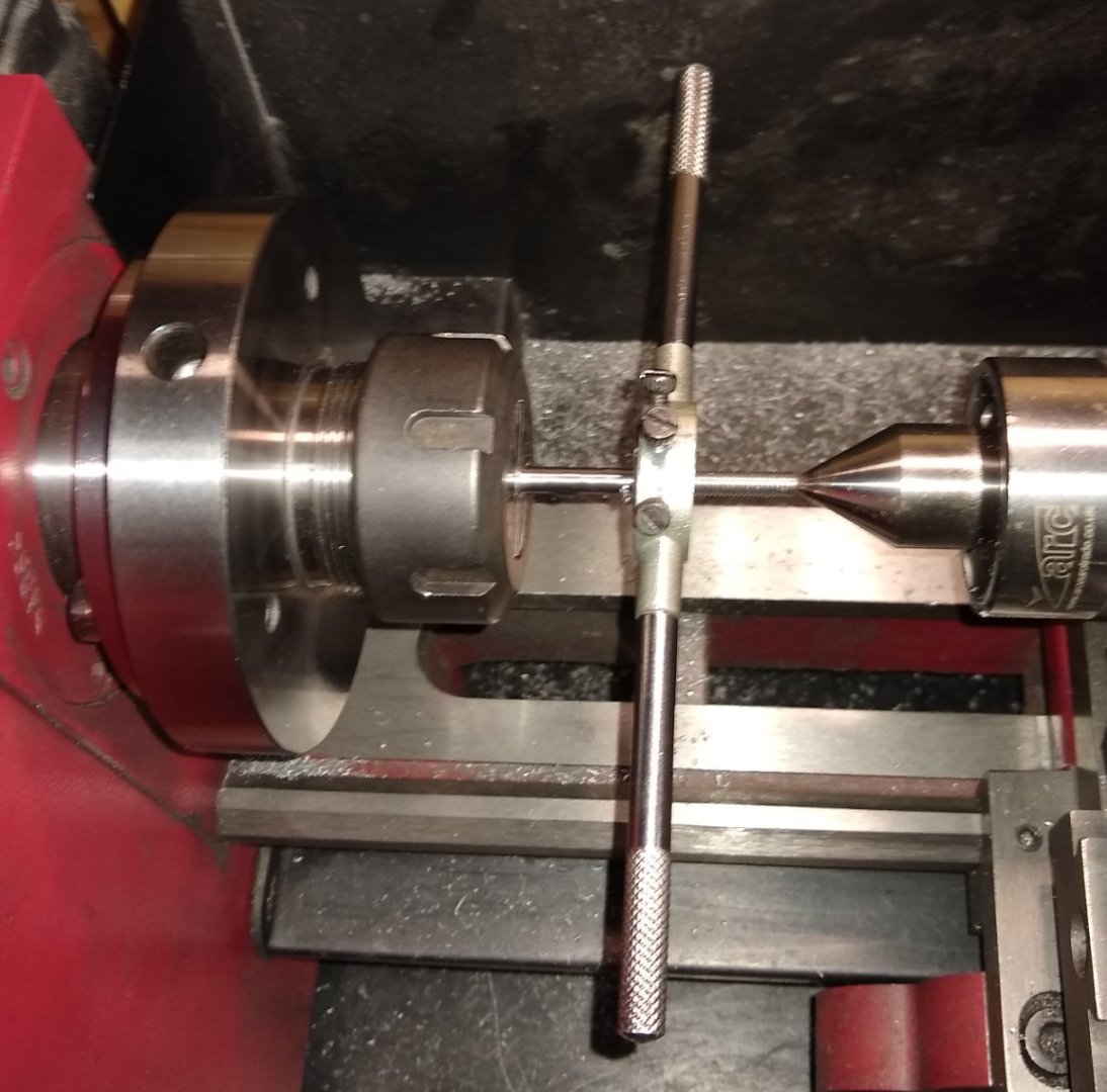
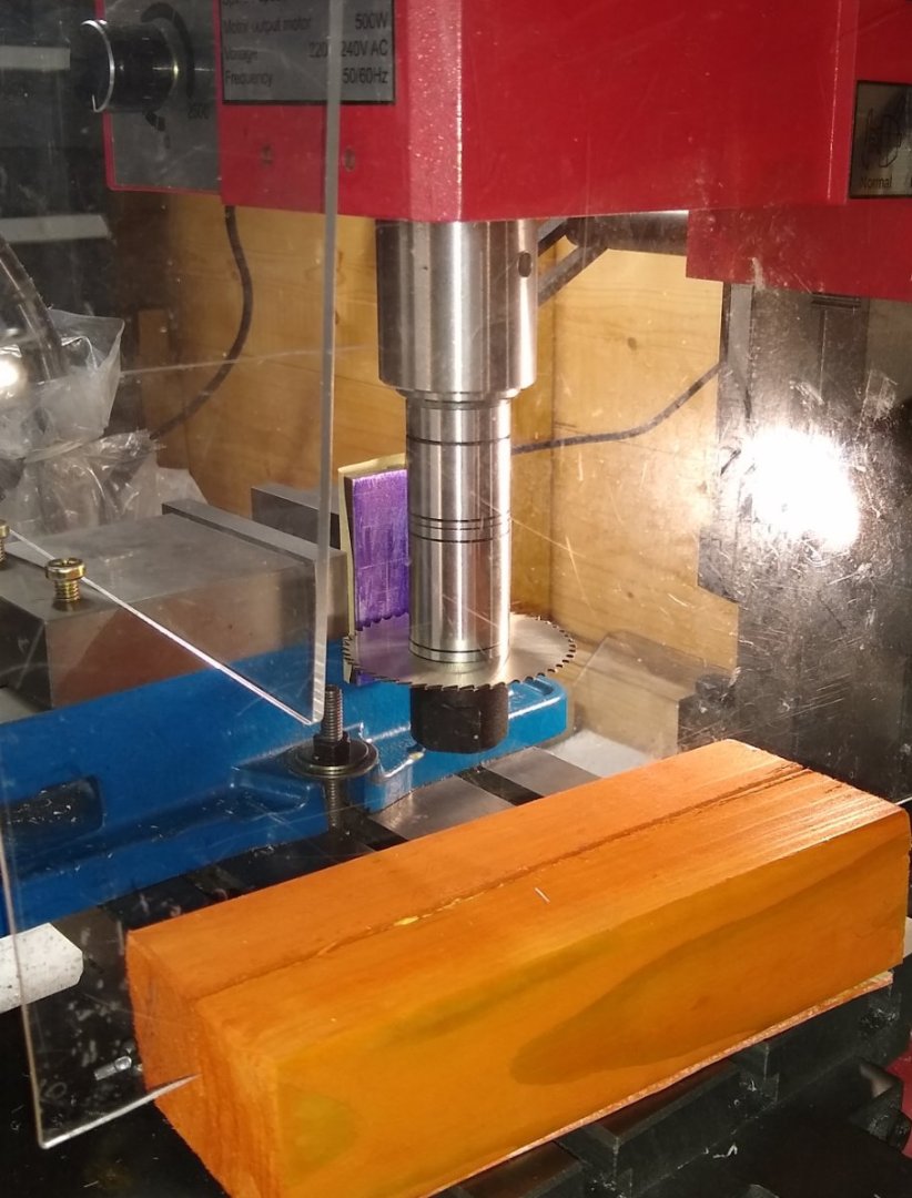
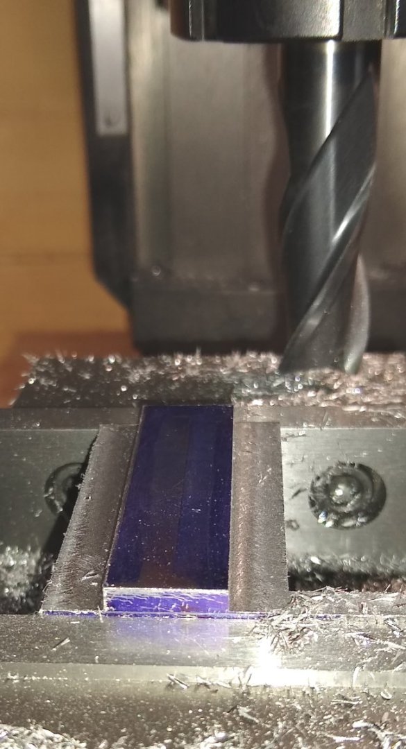
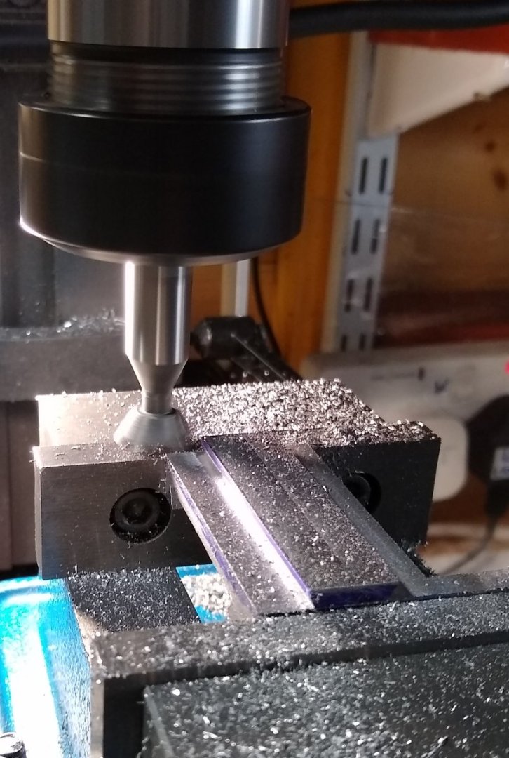
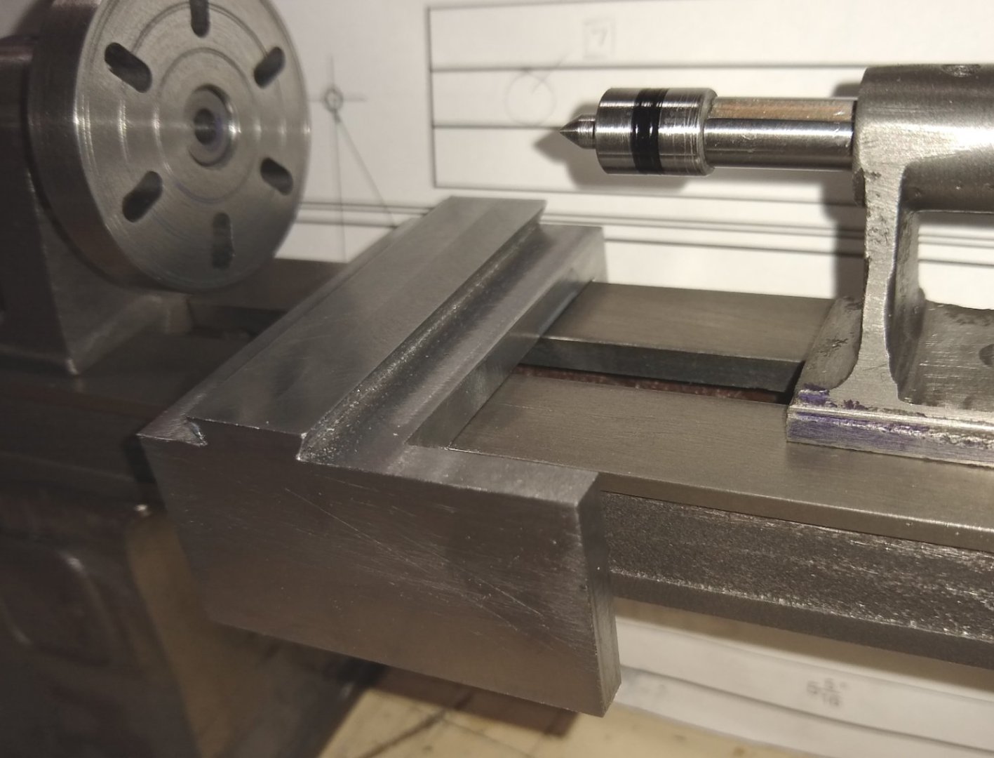
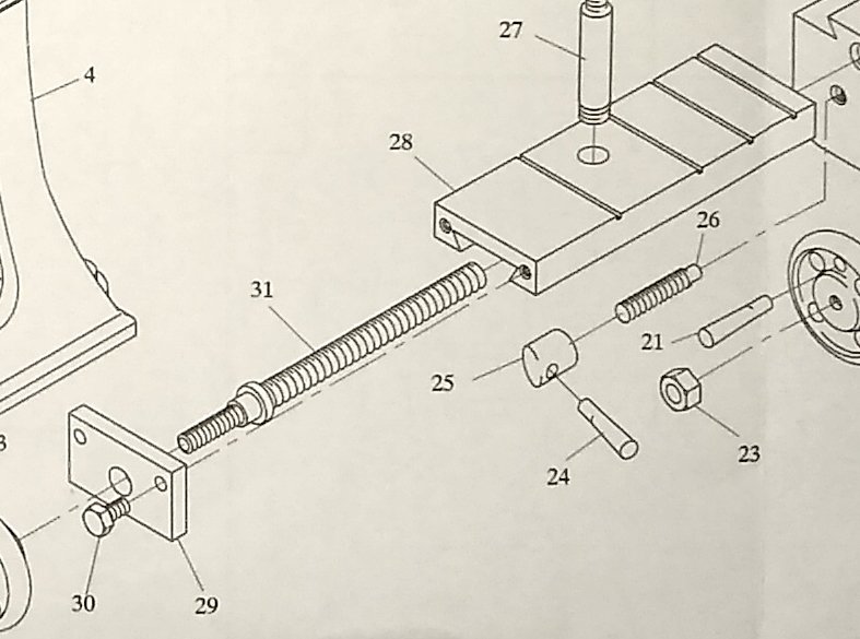
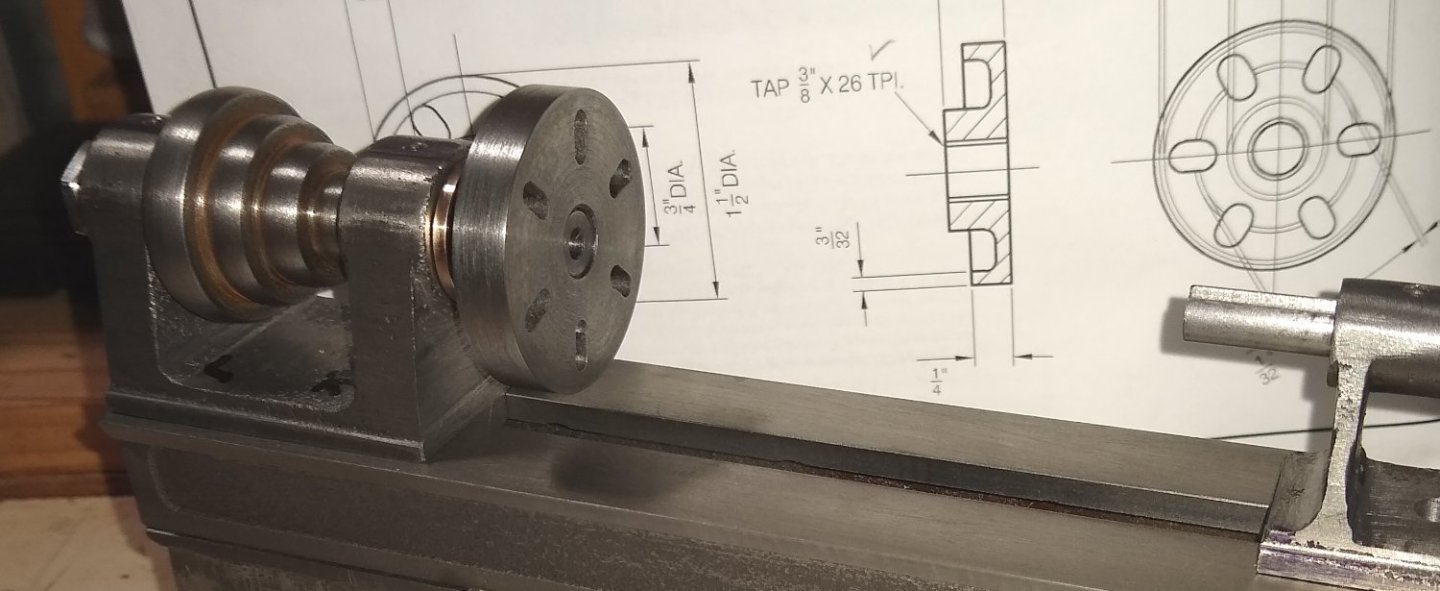
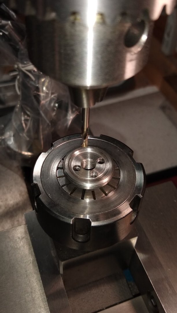
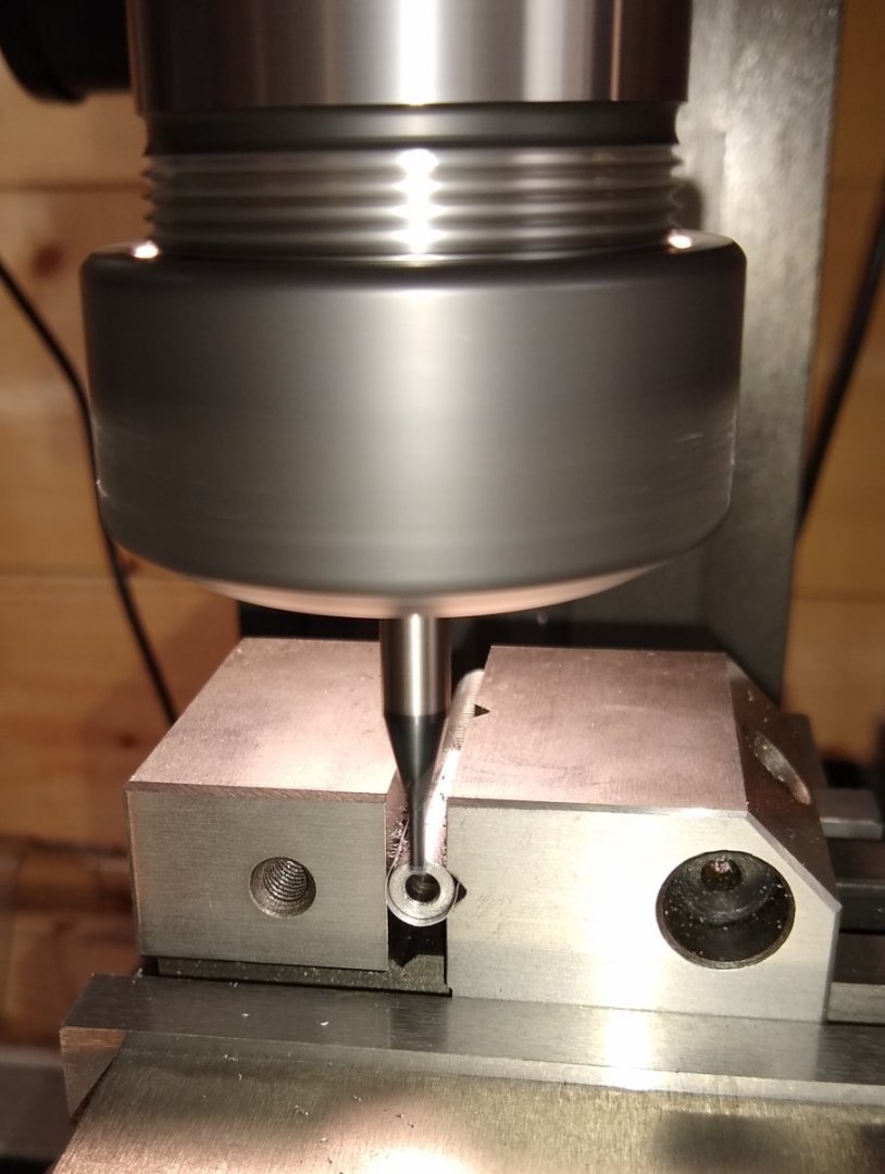
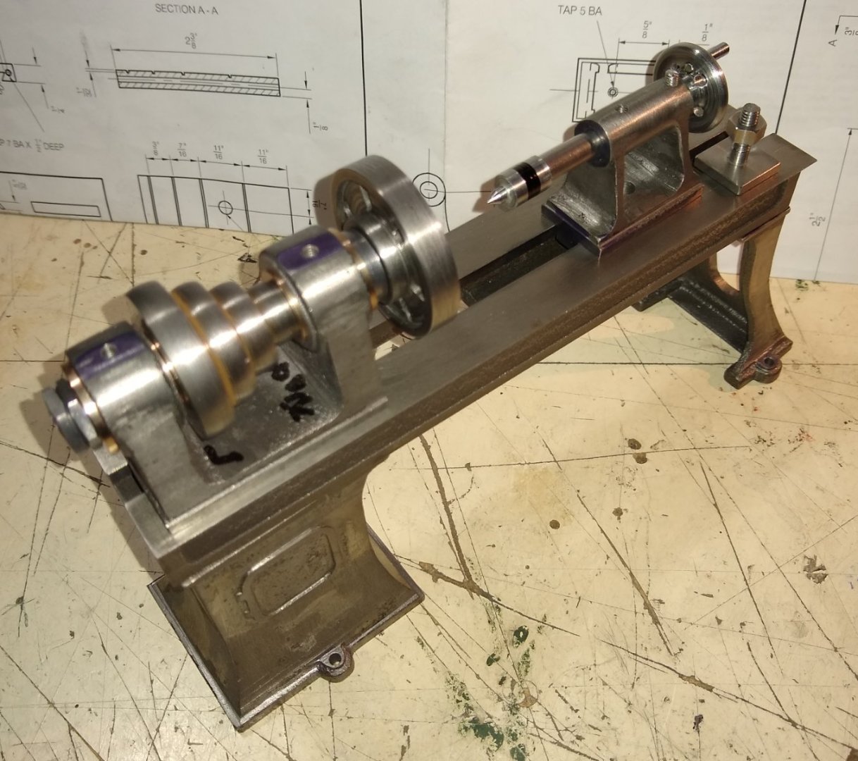
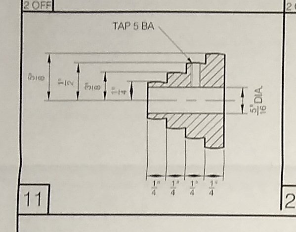
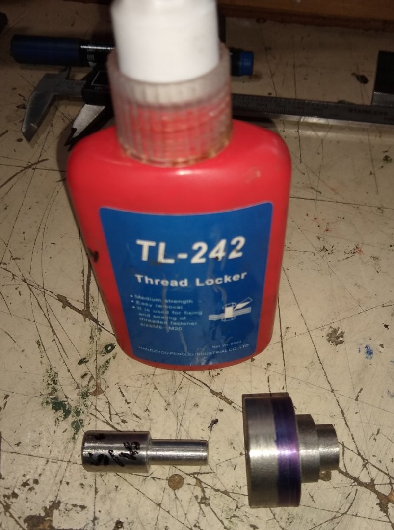
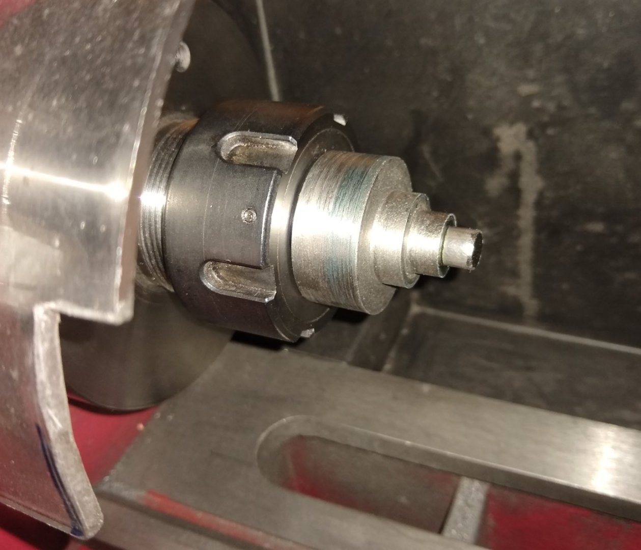
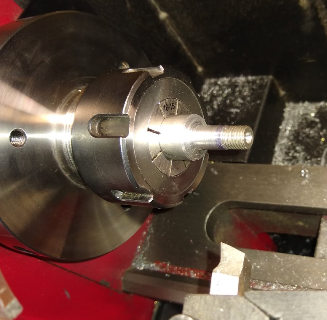
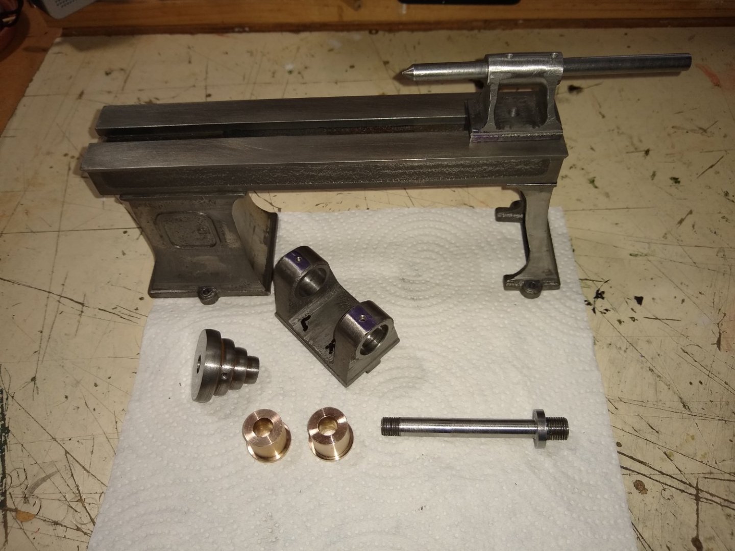
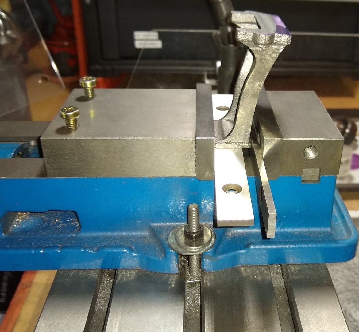
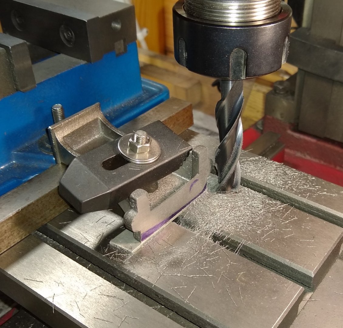
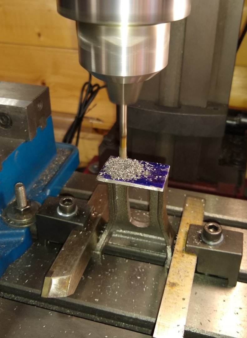
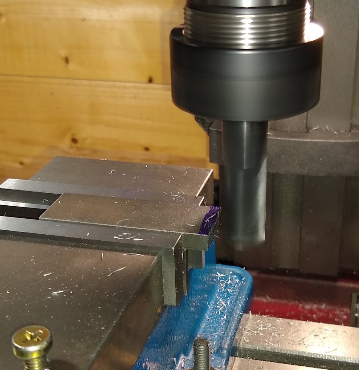
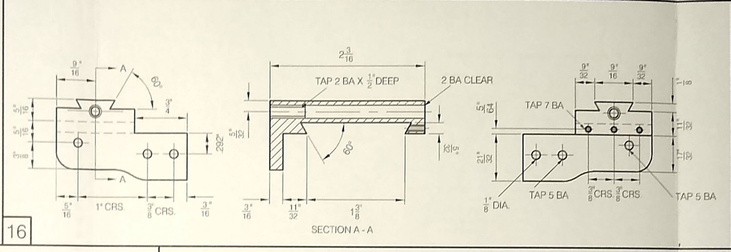
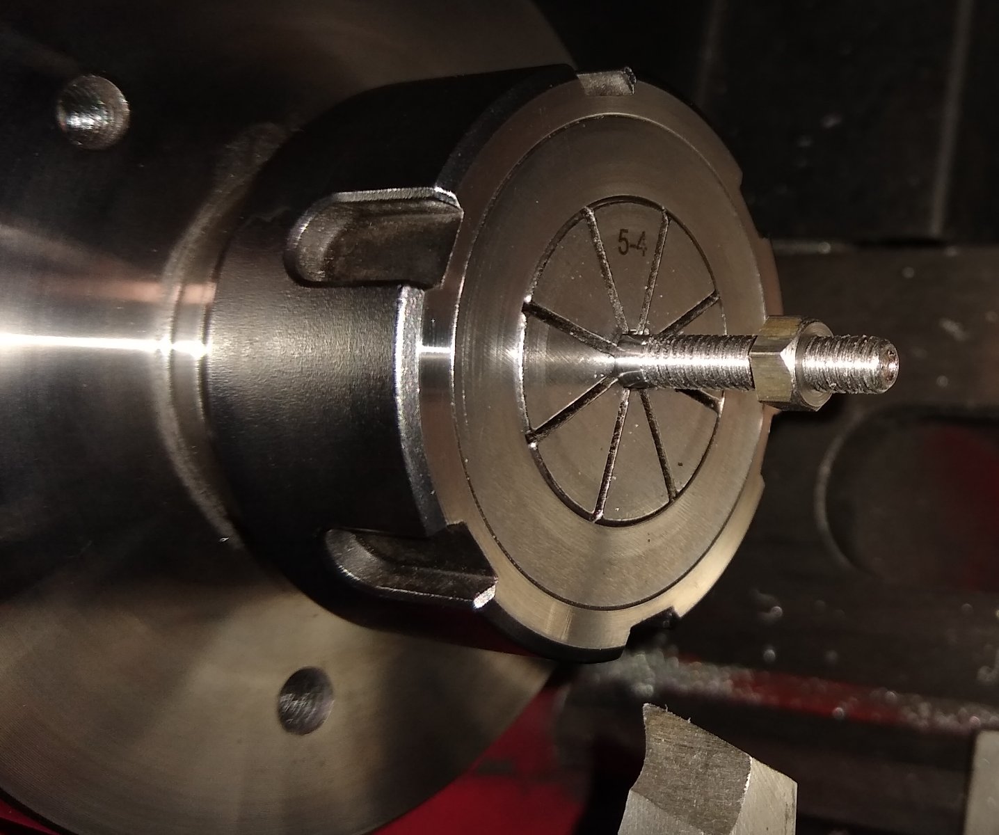
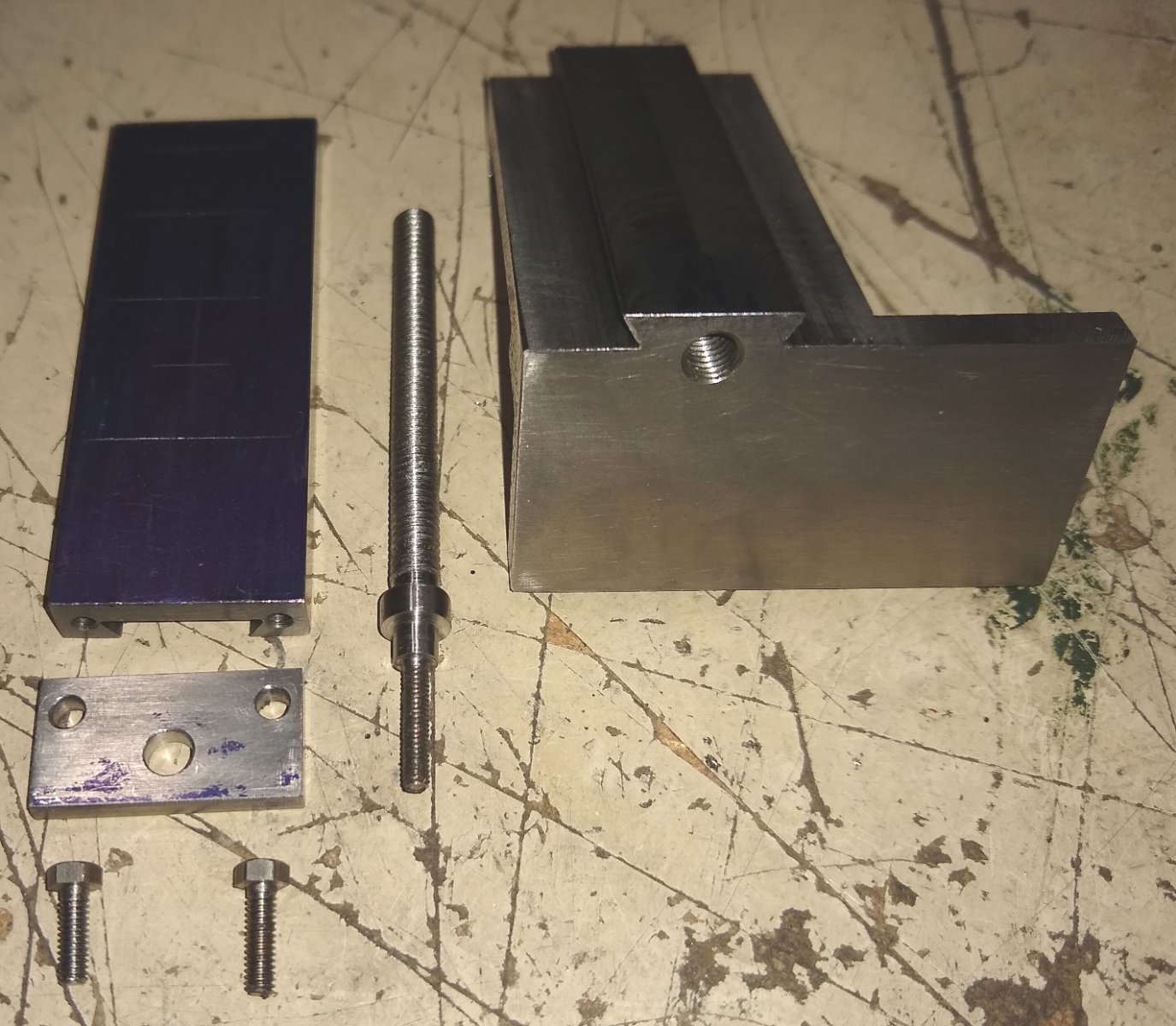
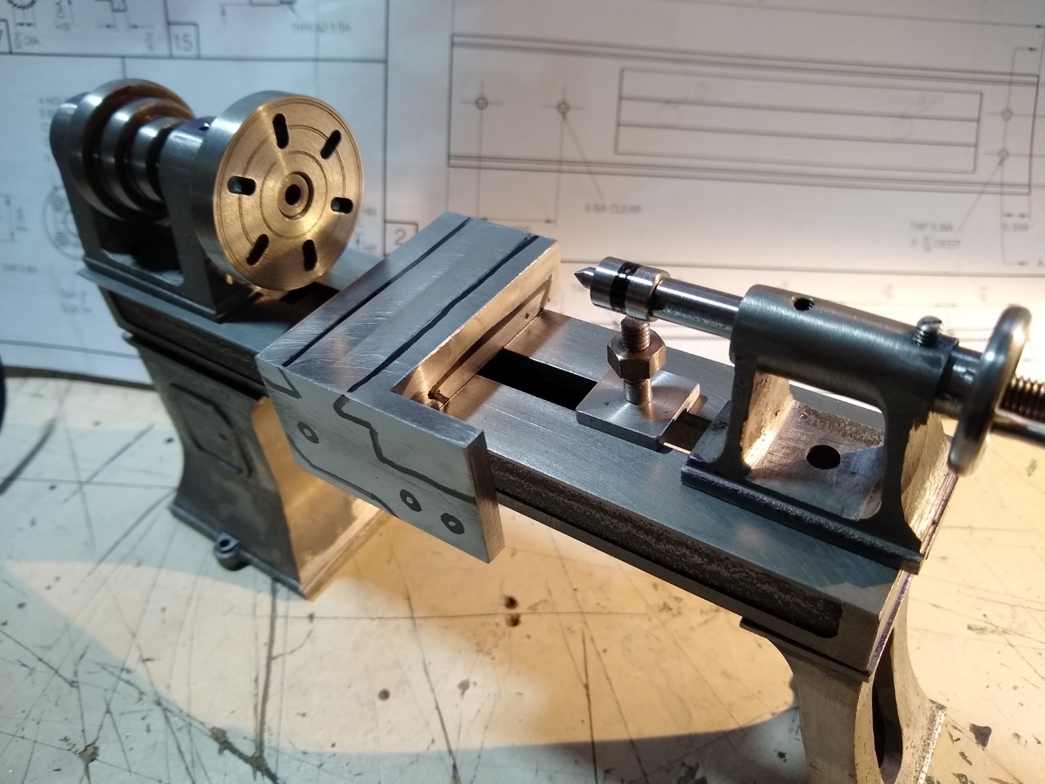
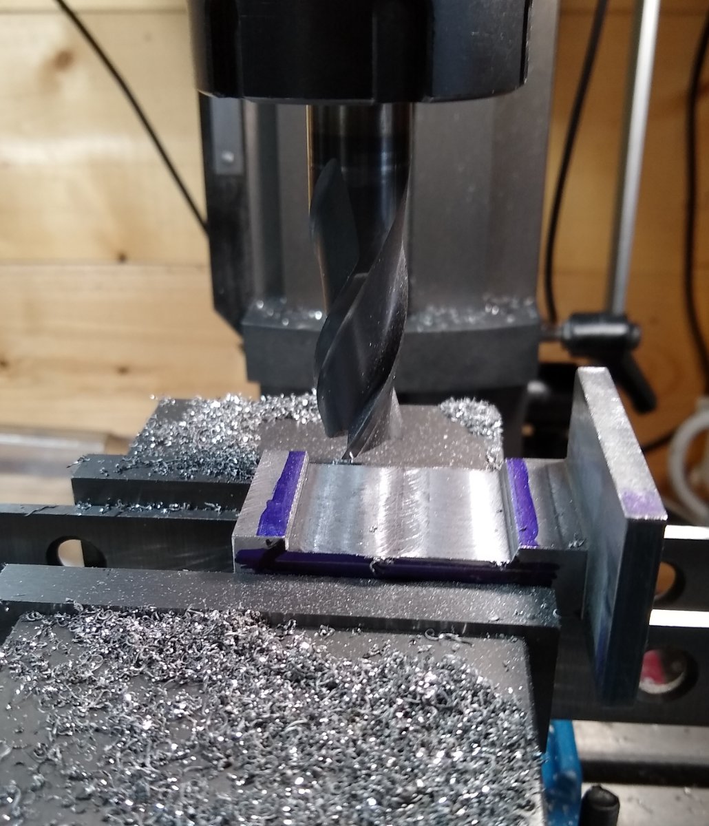
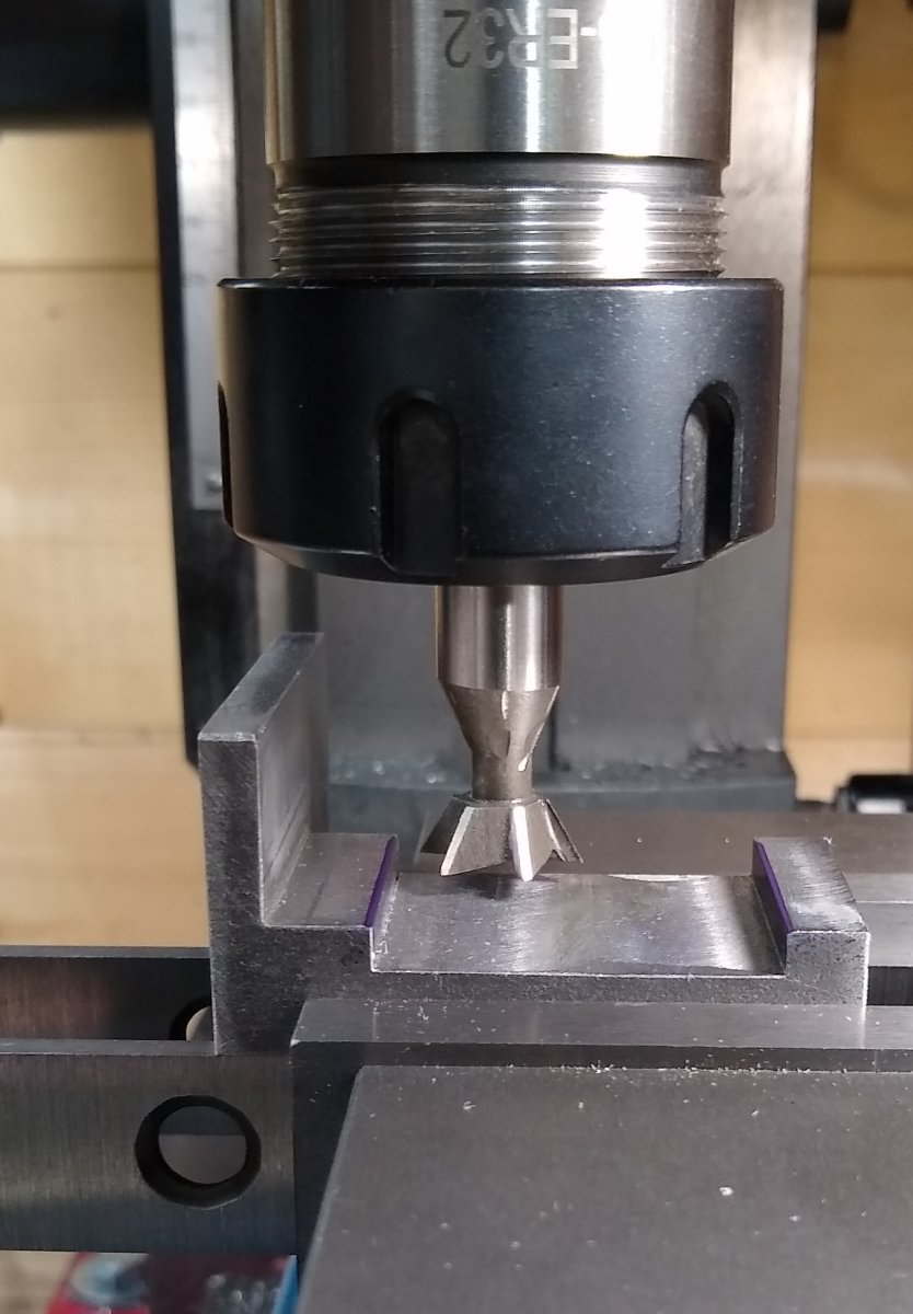
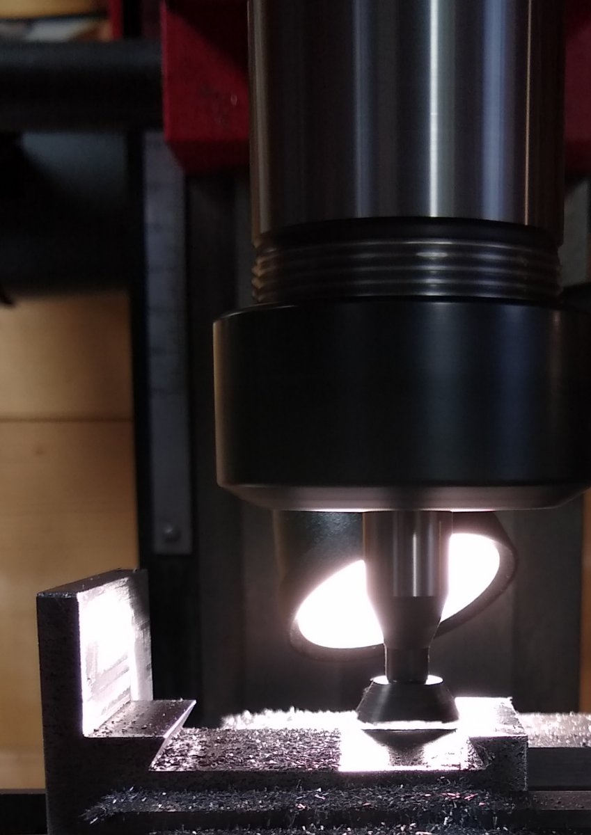
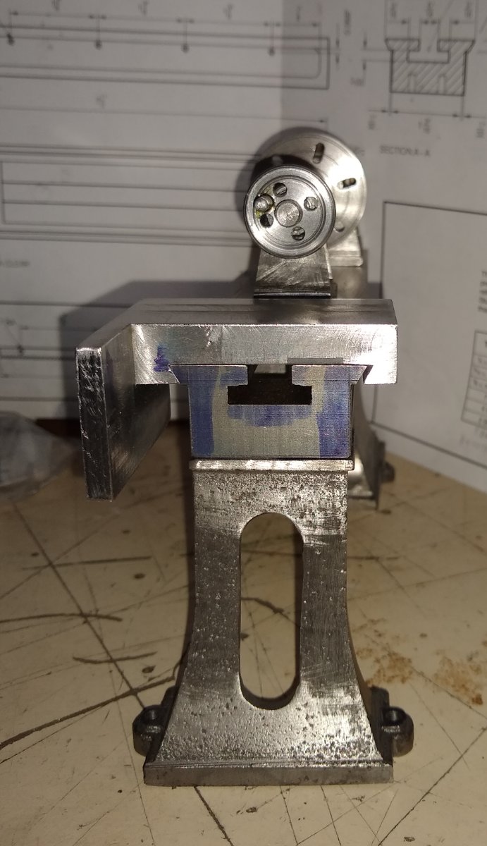
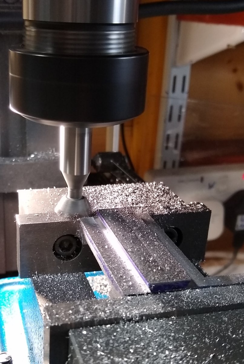
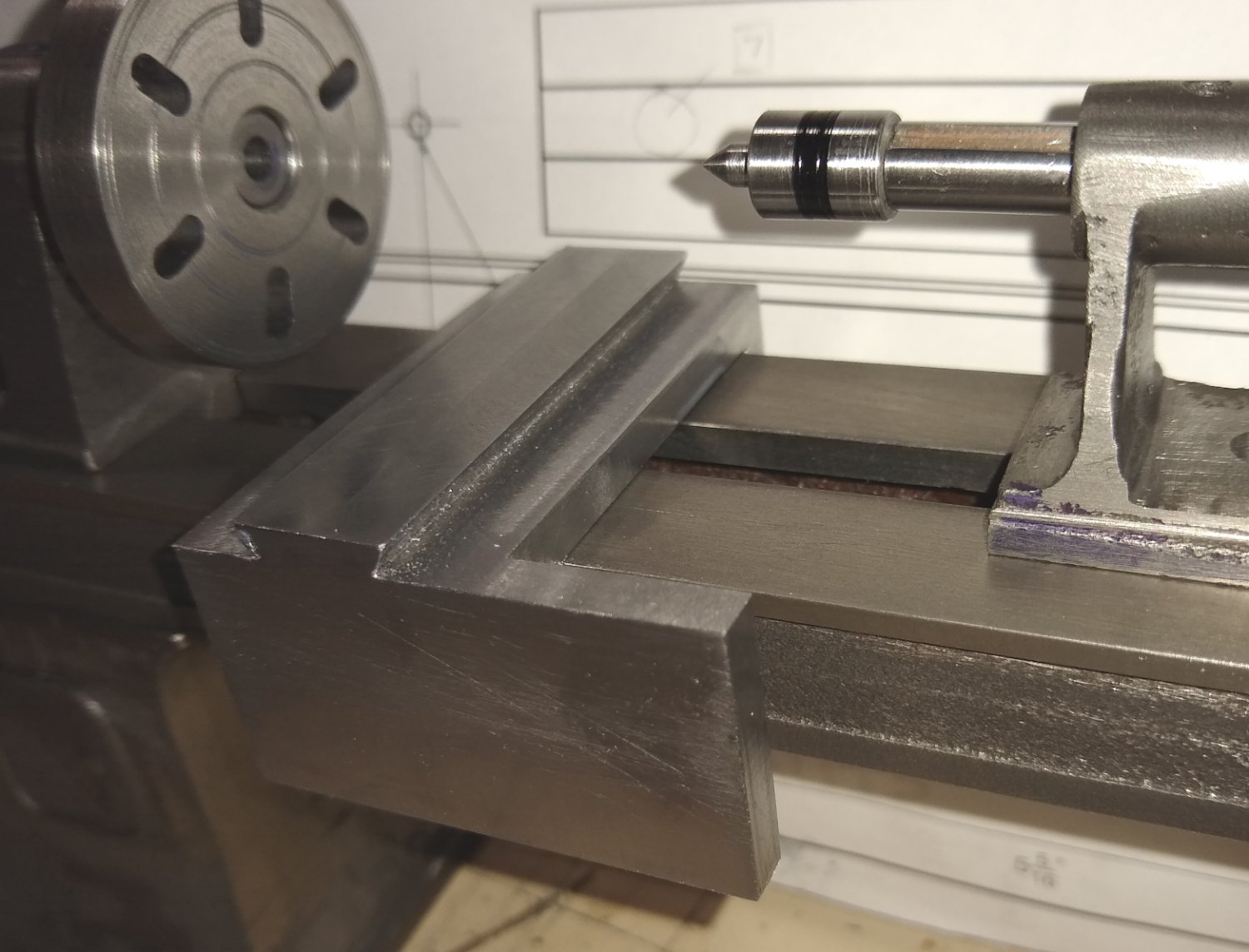
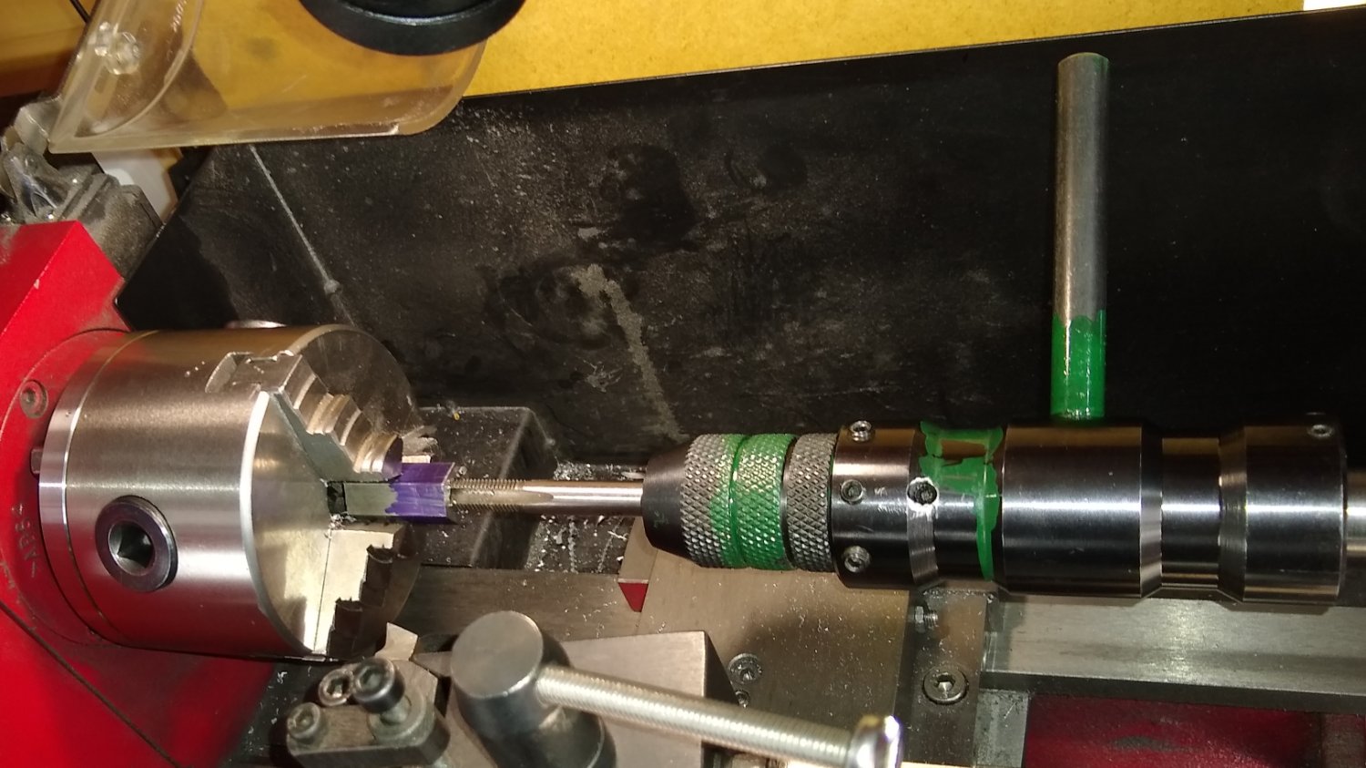
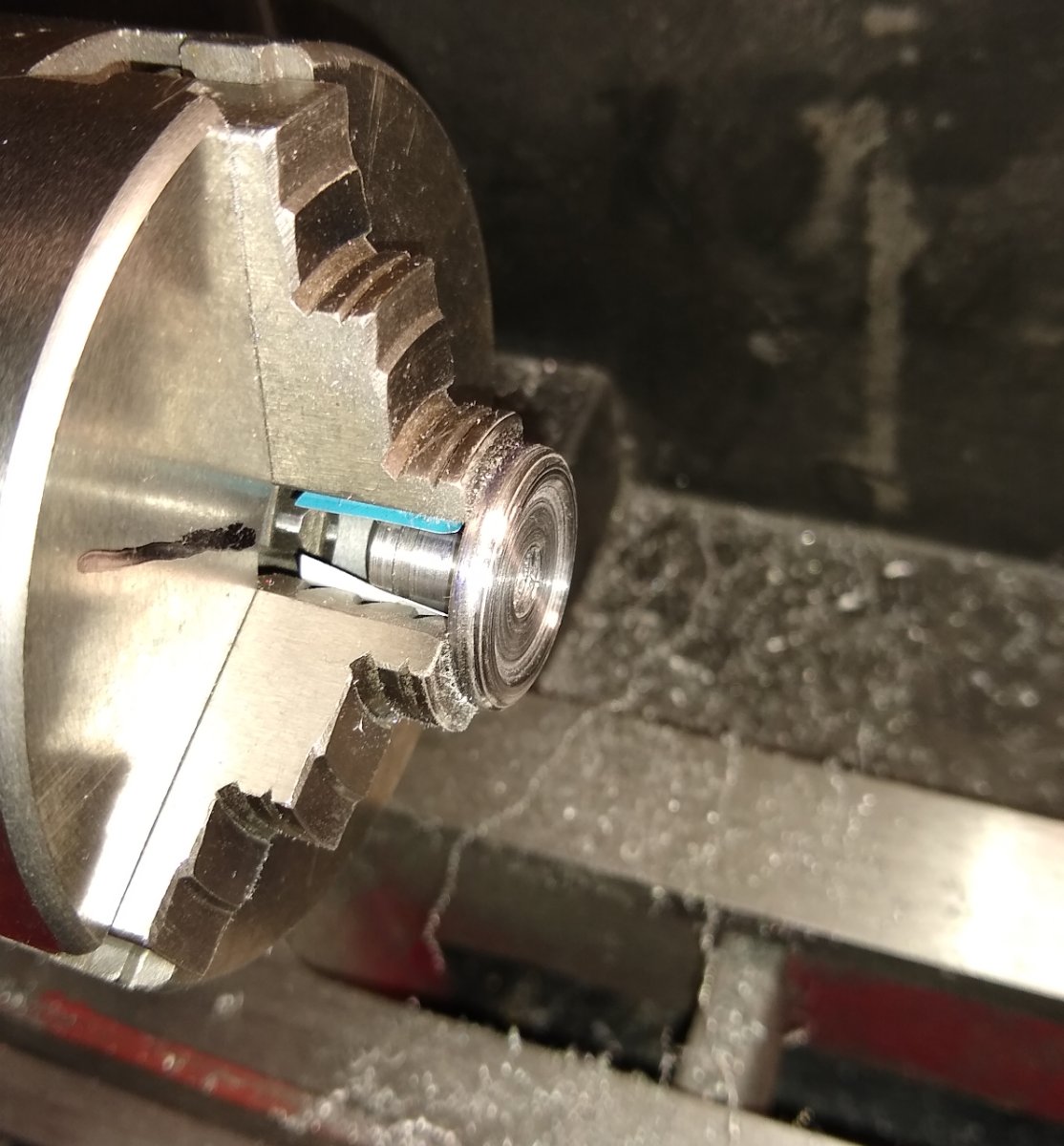
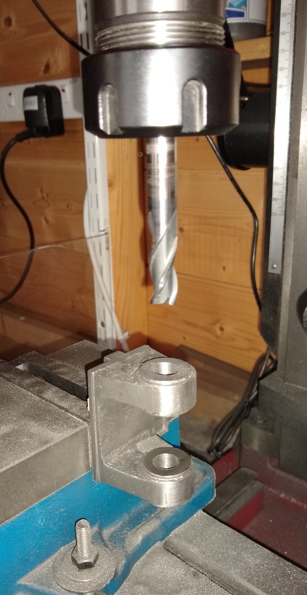
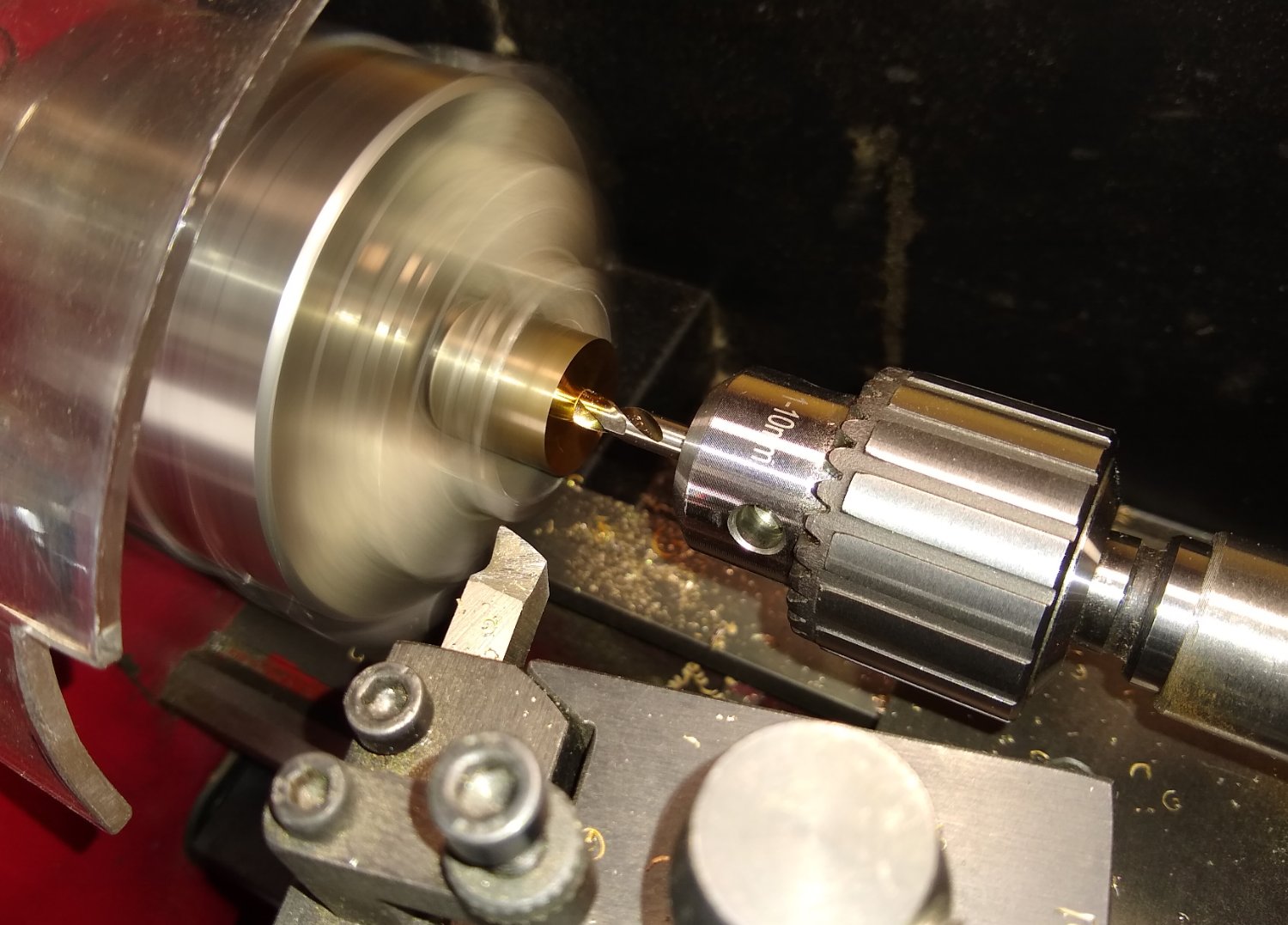
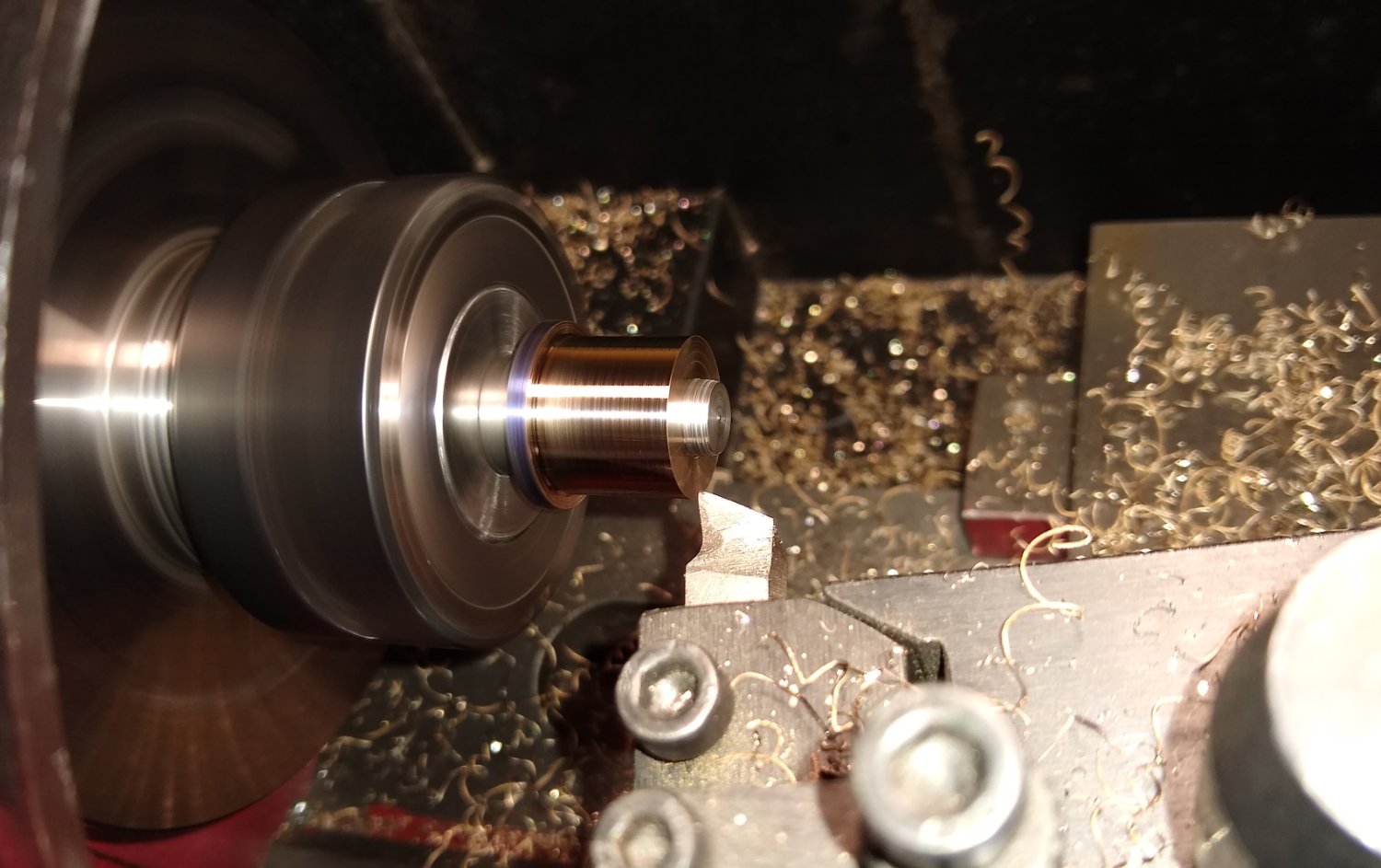
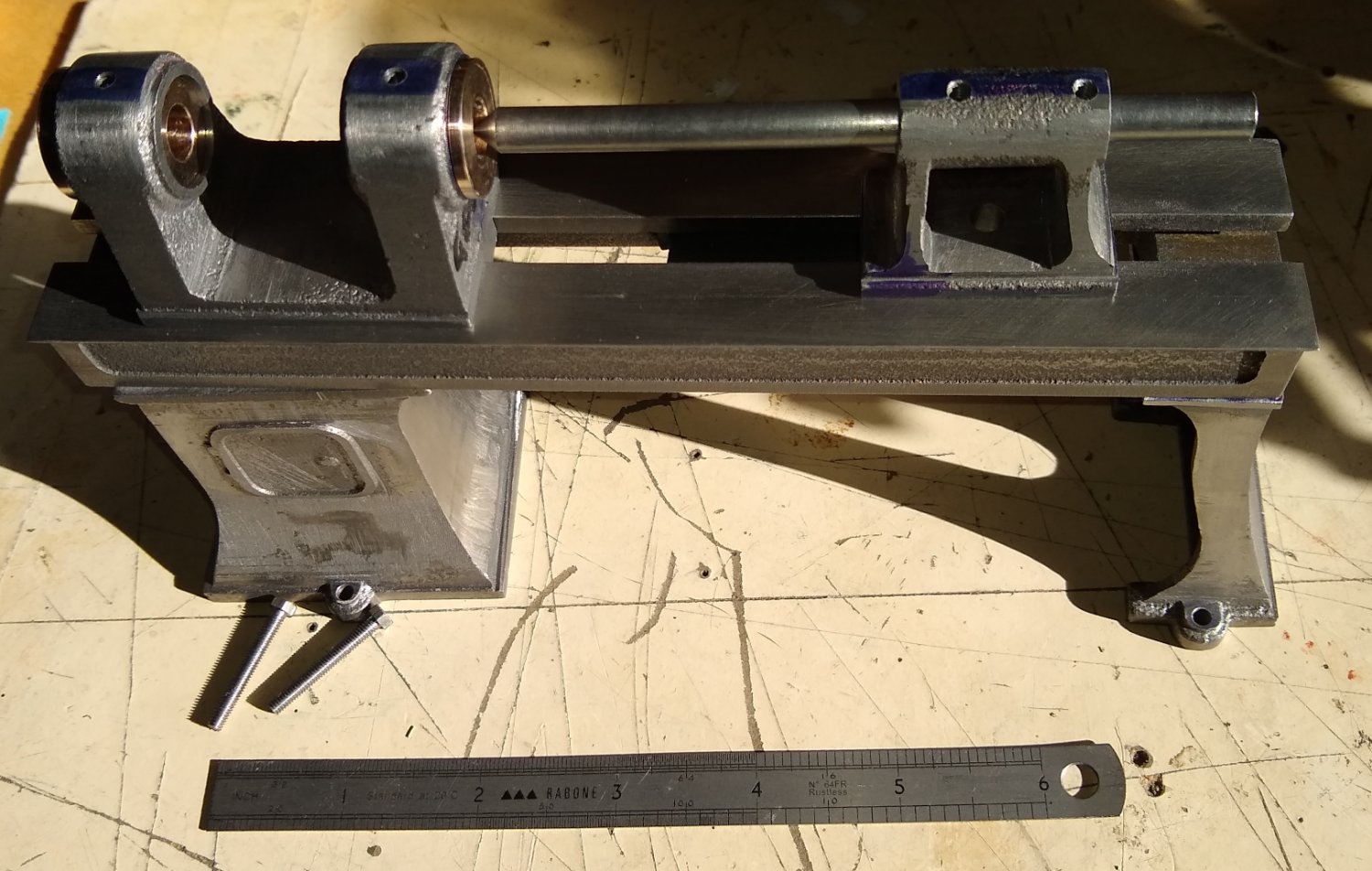
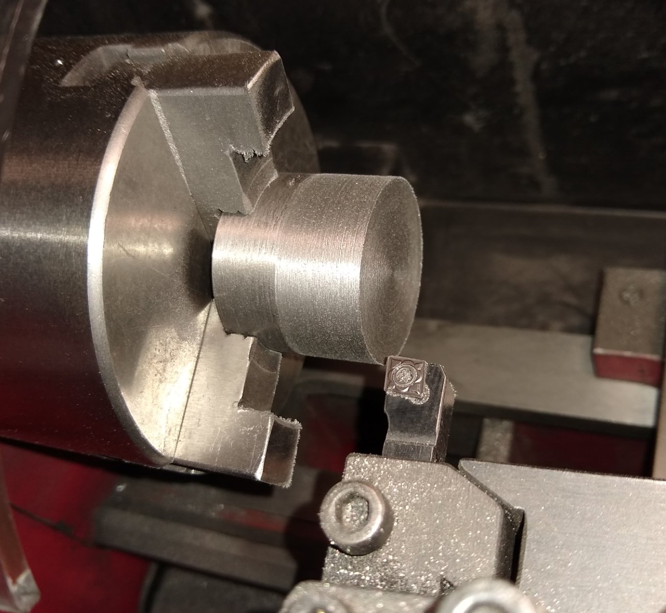
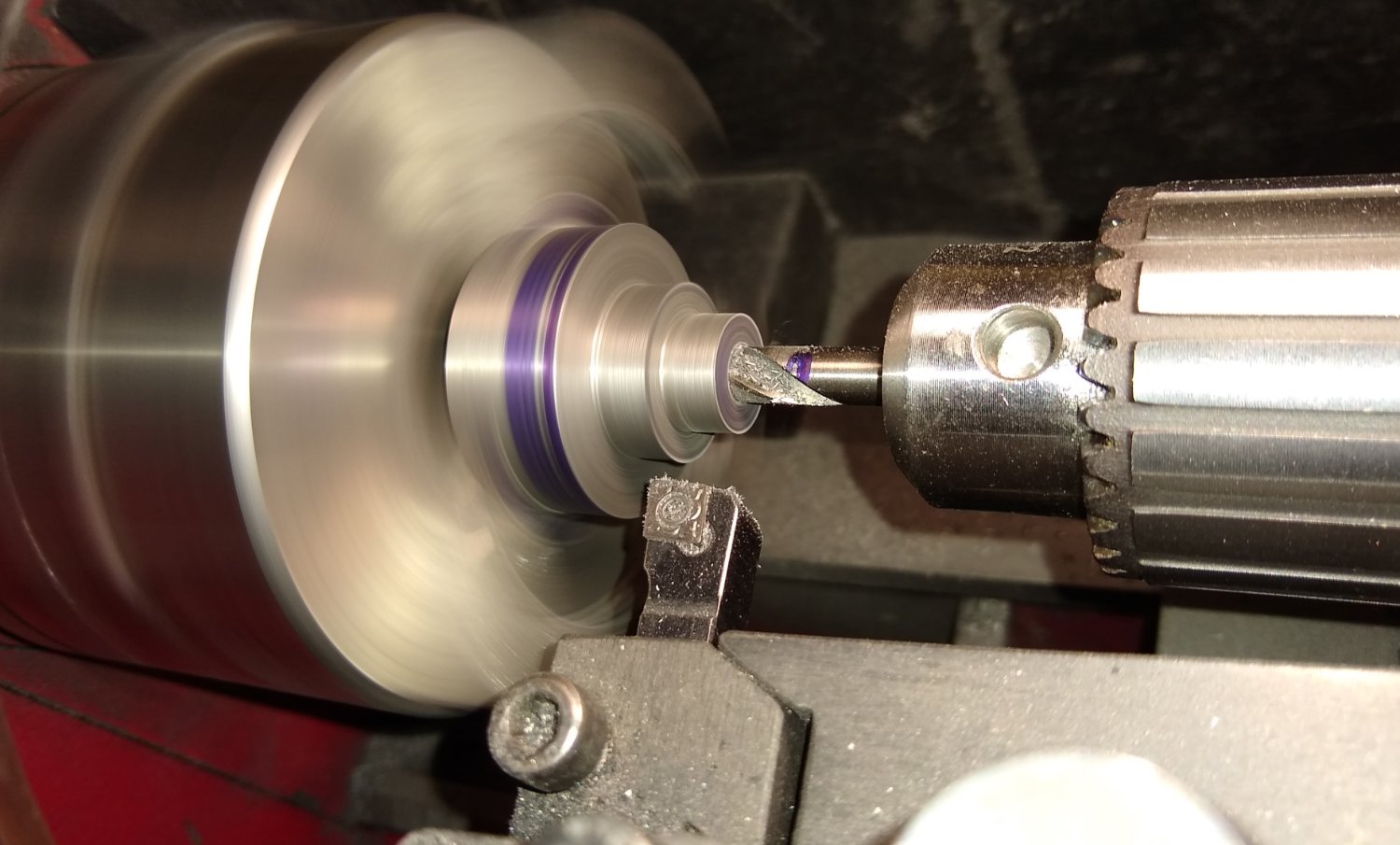
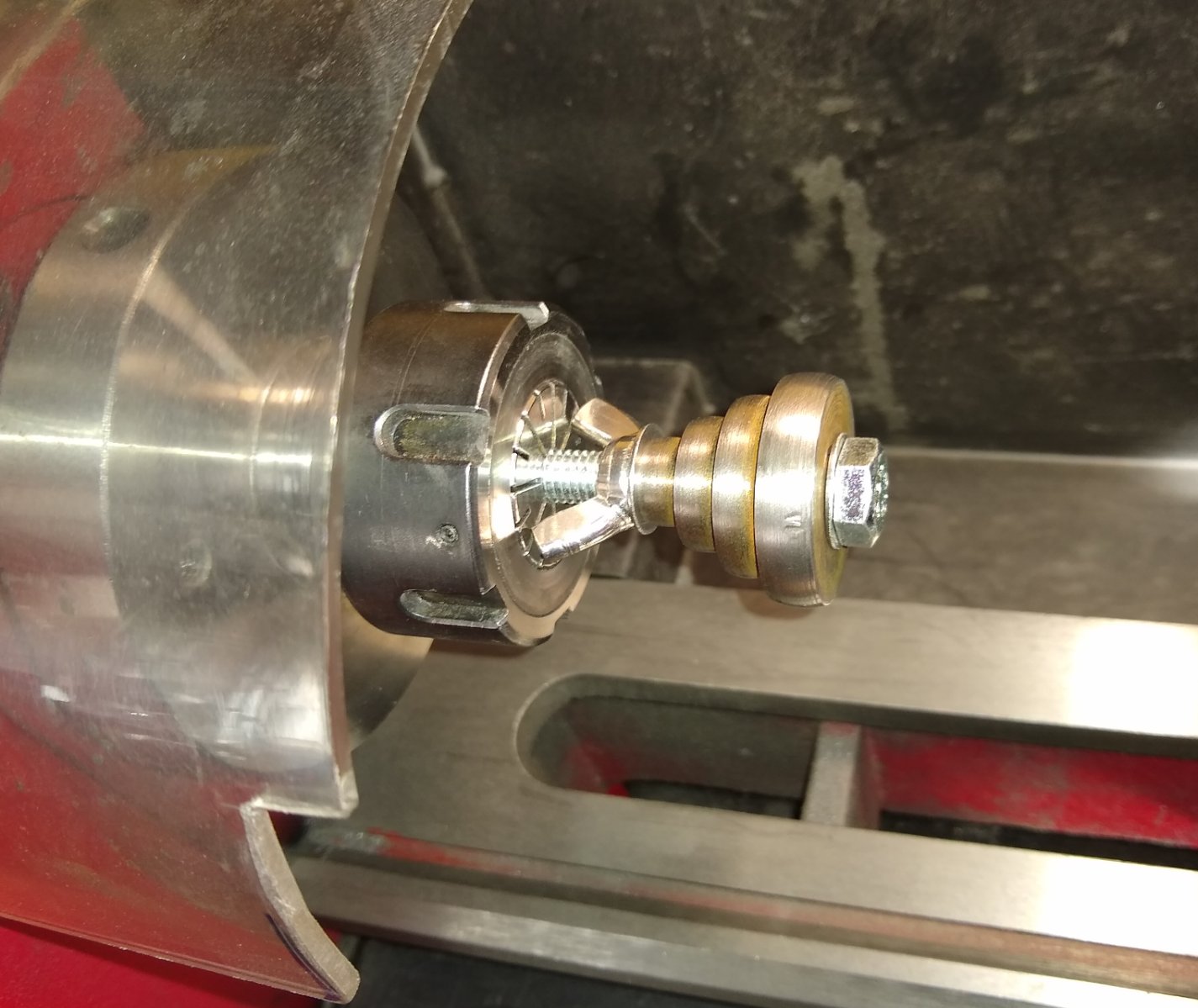
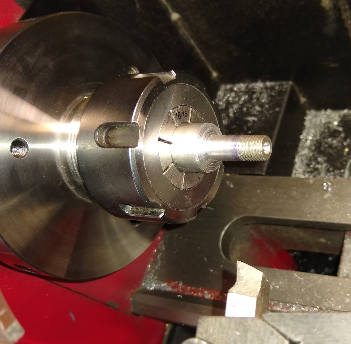
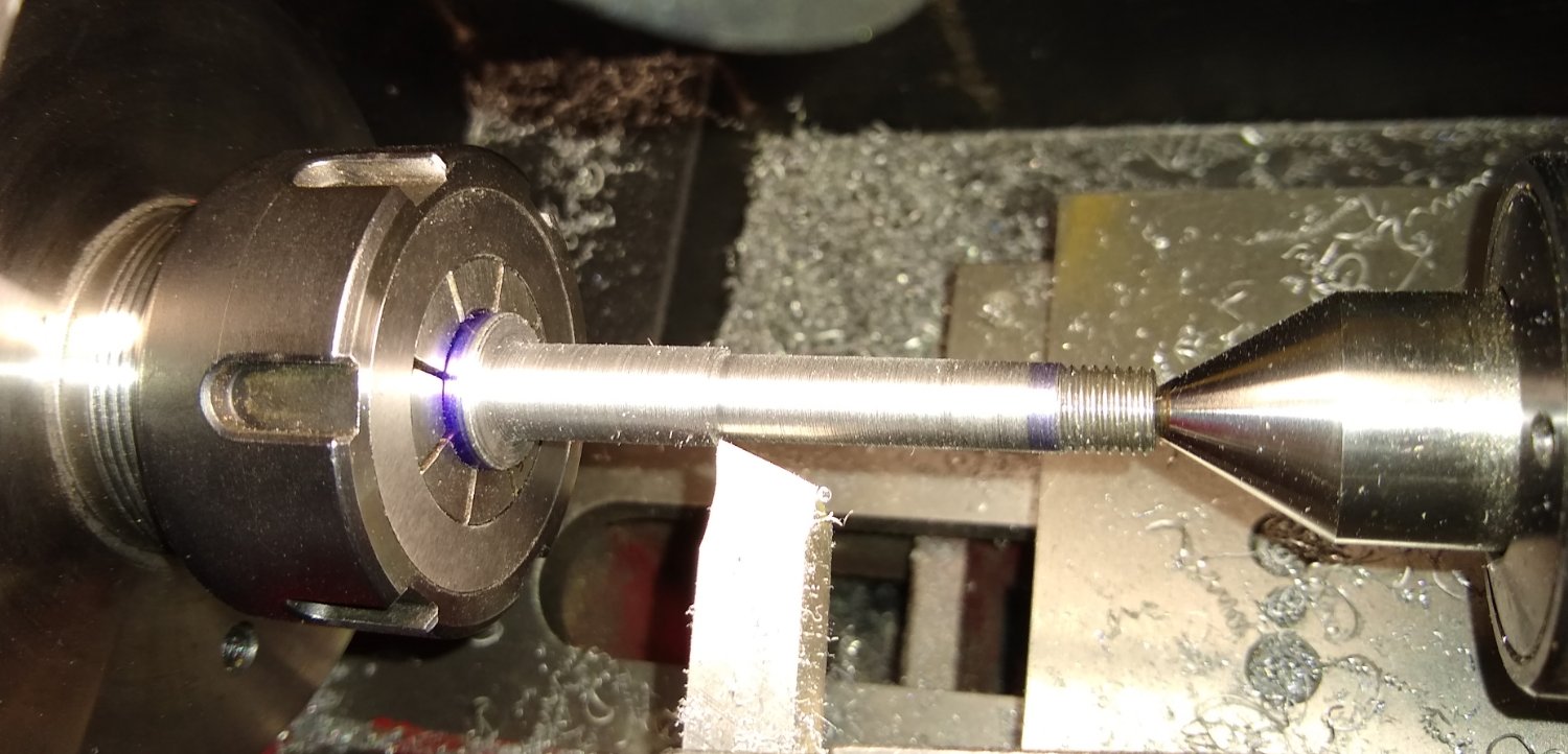
 Hi all, This post will focus on the lathe's Cross Slide (Pt 28), which mates with the Saddle's top dovetail. Below, a reminder of the grand plan. And here is the Cross Slide. Pts 29, 31, 28, 27, and the Saddle (Pt 16) should all make an appearance today 😉 But first, the main character, the Cross Slide. It's female dovetail mate's with the male dovetail slot on the top of the saddle. A sliding fit would be a good result, but in real life there would be an adjustable strip of metal (called a gib) to fill in the deliberate gap between the two dovetails - the gib is adjustable to compensate for fit and wear. The detail drawing of the Cross Slide. The two 7BA tapped holes seemed a tad too close to the corners of the dovetail slot for comfort, but I went with it anyway. The 2BA hole in the middle will accommodate the tool post column. Cleaning up the ends of the Cross Slide before milling out the bulk of the dovetail slot and then using the 60 deg dovetail cutter. And jumping ahead to the Cross Slide fitted nicely on to the saddle (...yup, I forgot to take pics of the dovetail being machined, but it looks just like the saddle machining did). The relative movement of the Cross Slide and saddle is controlled by a leadscrew. So the saddle needs a drilled hole to accommodate the leadscrew, with one end of the hole tapped 2BA (see centre view below). About to drill right through the length of the saddle with a 2BA tapping drill. 2BA tapping of the front end of the saddle's drilled hole. I'm using the chuck as a visual guide to help keep the tap wrench vertical. And now at the other end of the saddle, opening up the drilled hole to give 2BA clearance up to about 1/2" from the front face. This is the Leadscrew (Pt 31) that allows the Cross Slide to move relative to the saddle. As with a lot of parts I had to sit and think as to how to make this and in what sequence - that's a long, spindly 2BA thread! I decided to make a centre hole in the end of the rod, hold that end in a live centre and the other end in the collett. Then machine the diameter, in two sections, down to the 2BA threading size. The leadscrew, with a 7BA thread on one end (it should have been 5BA...whoops) , locating diameters and bare 2BA portion ready for threading. I tucked the leadscrew in from the back of the collett to give a strong start to the 2BA threading process. This was as much as would stick through the collett - I don't think I'd want any more anyway. And a 2BA die holder located on the tailstock to keep things square. A 2BA nut threaded on to check the thread had been cut to a reasonably snug fit. Now the leadscrew is taken out of the rear of the collett and re-located back on the live centre. And a simple die holder used to finish the threading. I couldn't use the 'green' die holder for this since there was little material to be held square enough in the collett. The Cross slide and associated parts. Pt 29 (the Keep plate) was finished 'off camera'. Almost there 😉 .... adding some fake T-Slots to the Cross Slide. I'm always very wary of slitting saws for some reason, hence two plastic guard sheets on duty. And finally, the Cross Slide fitted to the lathe. The toolpost column was also done off camera. It all fits together well and the Cross Slide (sans wheel) moves smoothly over the saddle. This post describes machining that is probably a bit nitty-gritty, but needs to be done nonetheless. Although it may not seem that exciting I found that I spend about 80% of my time measuring and planning what to do rather than doing.....just like model ship building I guess 😉 Thanks, Richard
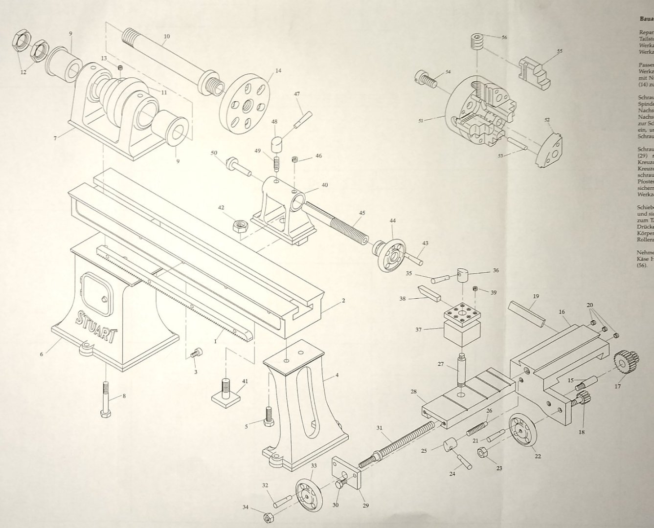


-
Roger, EG, Thanks for the comments. I find sketching a useful aid, and having been, in the earlier part of my career, a trained design draughtsman (BS308) it kinda comes naturally to me. Machining on the other hand, I feel I have a ways to go, which is fine since learning is enjoyable. Some of the machinists on YouTube are an order of magnitude away from me but that is their forte. Clickspring, although not a heavy machinist, displays some extraordinary skills and patience .... https://www.youtube.com/c/Clickspring/videos ... not least his work on the Antikythera Mechanism. Richard
-
Wefalck, Yes, if one part was crying out to be a casting it might be the saddle. It certainly would have saved me a lot of hacksawing, good exercise as it was. But, as you say, clamping would not be so easy on a casting. And as there was quite a bit of heavy machining going on, I wonder if a skinny cast iron part may have cracked, particularly with the hard outer skin on Stuart's castings. When I say 'heavy' the deepest cuts I tend to take with my end mills are about 10th (0.25mm). My milling machine isn't particularly sturdy and starts to vibrate if I go much above 0.25mm. But it is what it is, and for the price I paid, very good. Also a larger more powerful machine could get me in to a lot more trouble so I'm more than happy to live with my mill's shortcomings. Richard
-
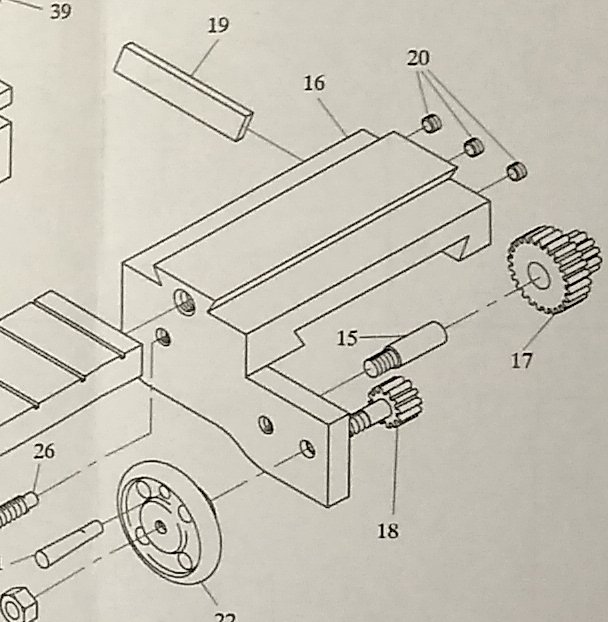
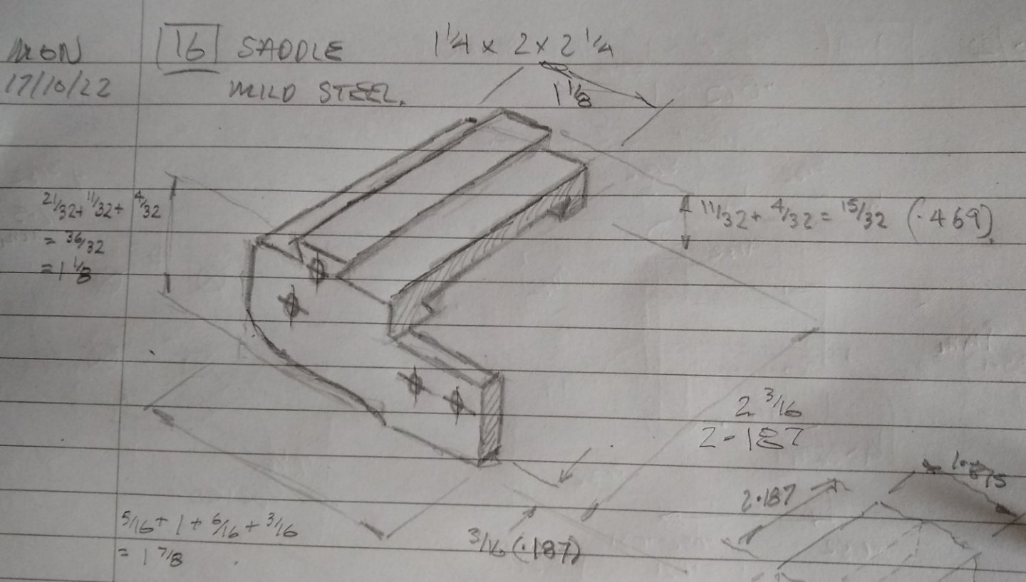
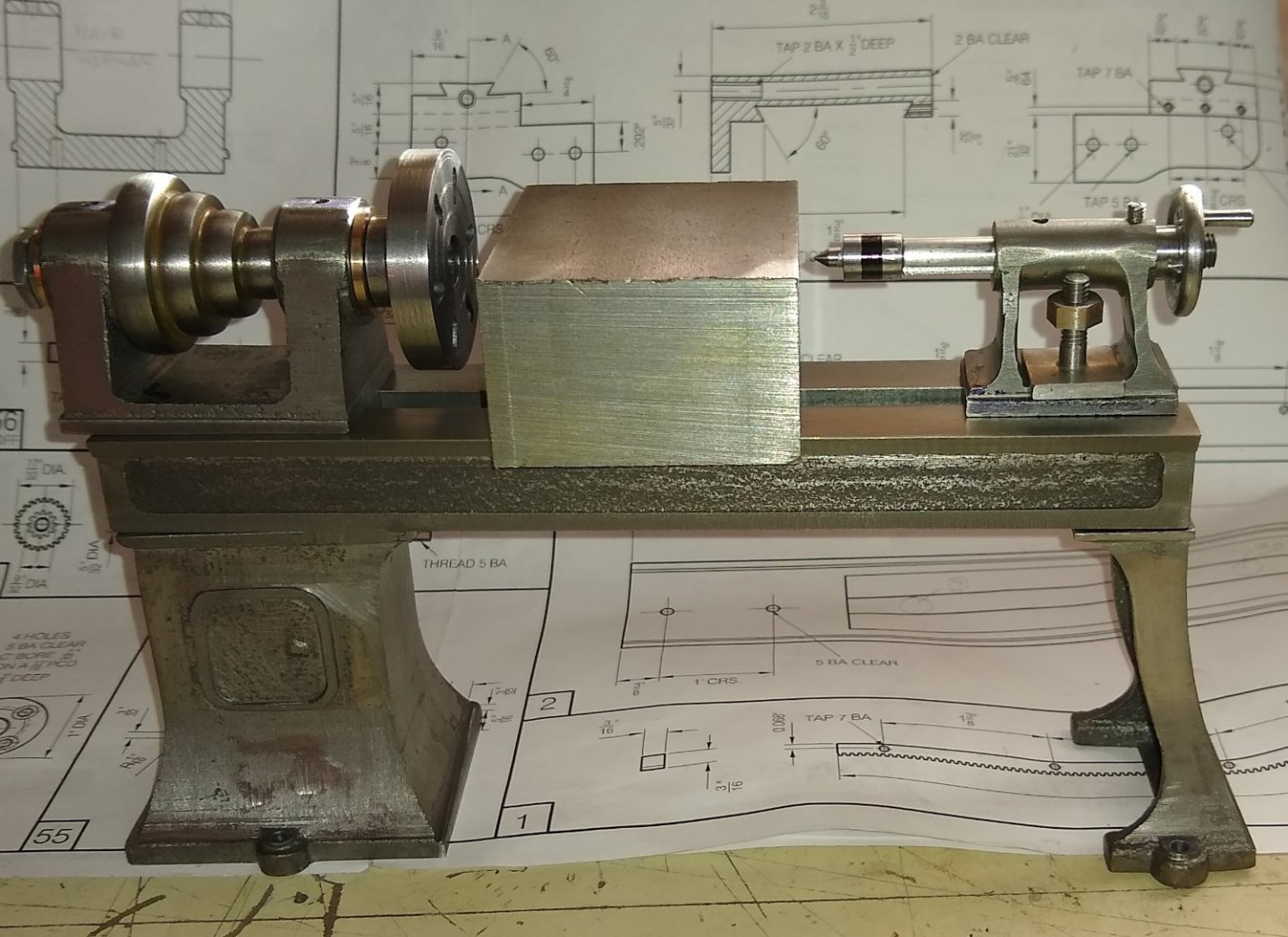
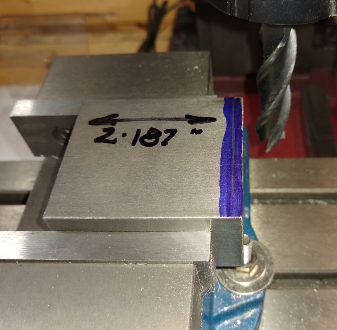
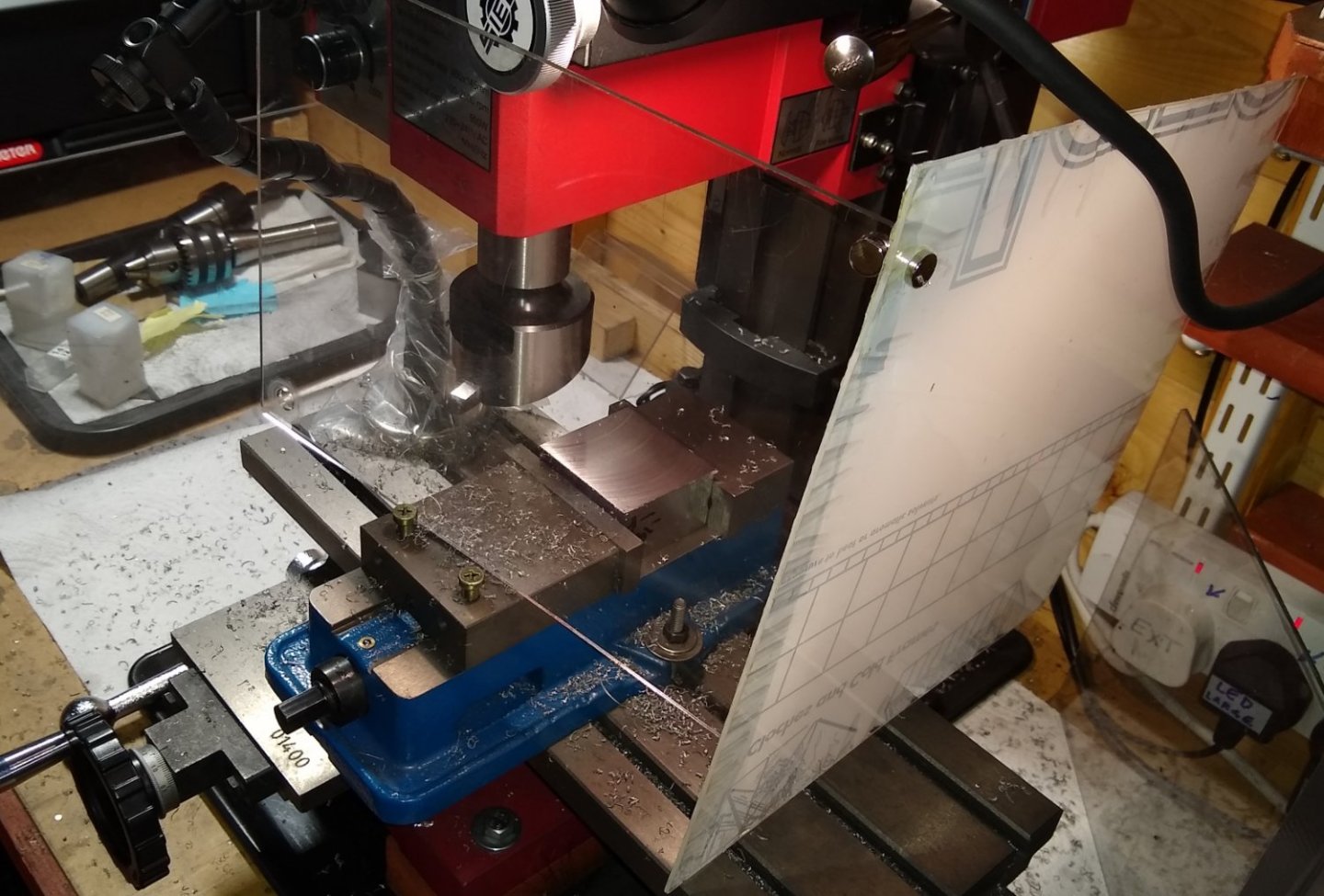
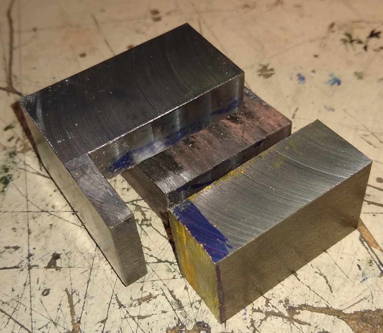
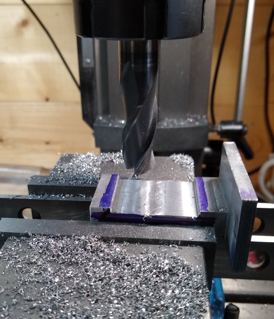
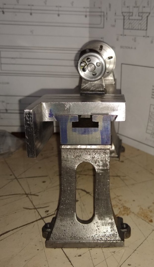
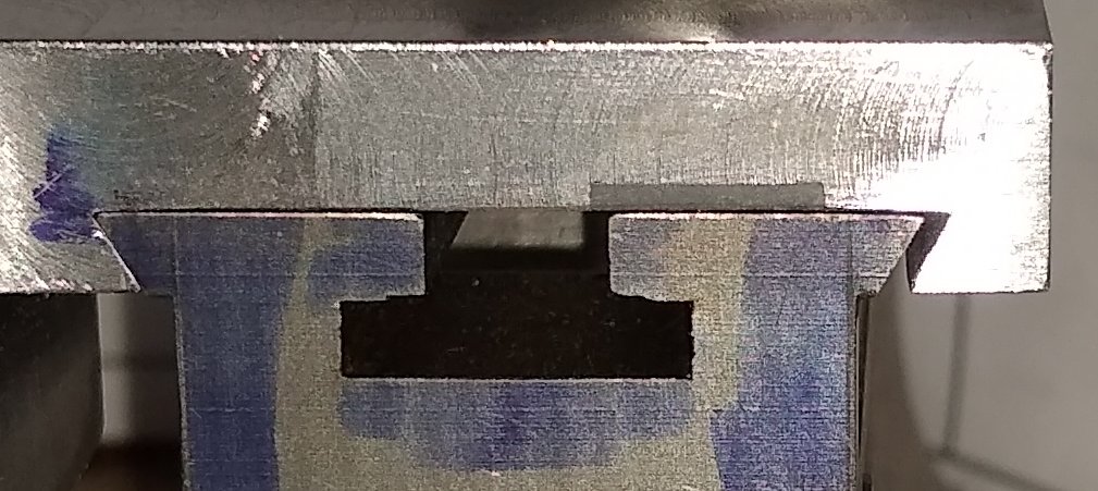
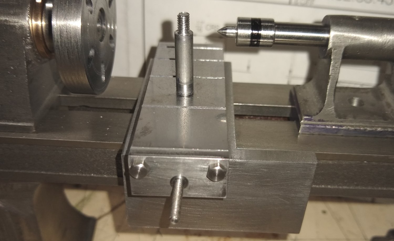
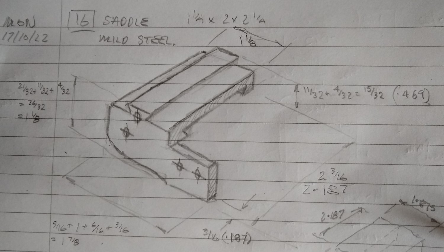
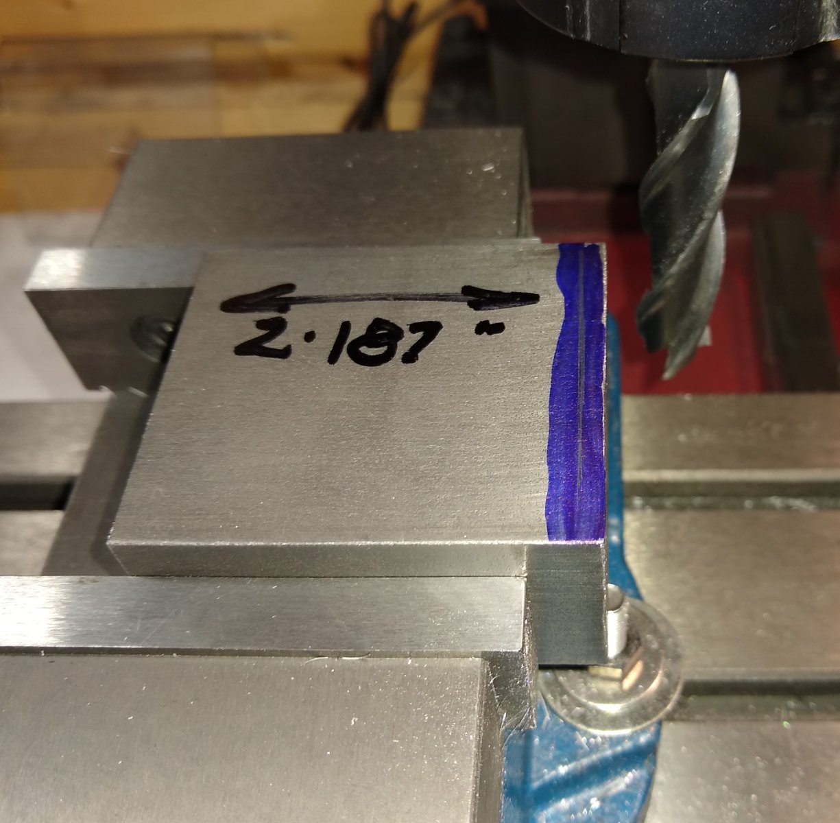
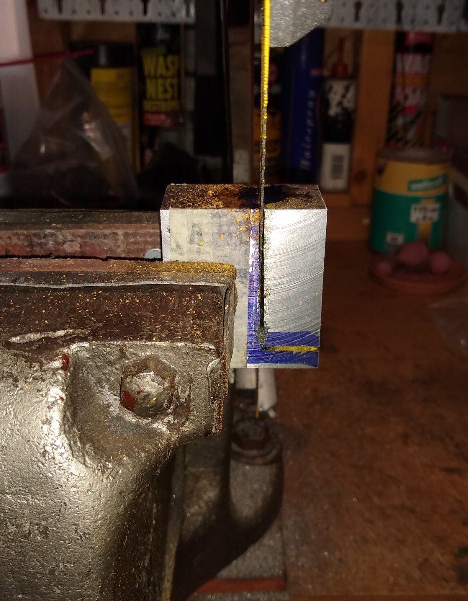
Hi all, This week's update on my Stuart miniature lathe's progress. Above, a reminder of where I am headed. And below, the subject of this post, Item 16 - the Saddle. The saddle is a fairly complex part with dovetail slots at 90 deg to each other and a number of holes etc. I'll concentrate today on rough machining the part to size and the dovetails. Below, I like to do a quick sketch of all parts I make since it gets my mind round what the part looks like, checks dimensions for correctness and/or omission. and helps formulate a plan of which order to machine the features and the appropriate clamping/work holding. With 'one-offs' like this I don't think there is ever a correct 'order' since people use different machines and have different skill sets, but my aim is to avoid finding myself halfway through machining the part and discovering I should have left meat in a certain area for clamping to, say...but unfortunately have already removed that meat. So here is the saddle, as it arrives from Stuart Models....a 2 1/4" x 2" x 1 1/4" lump of mild steel. After blueing the surfaces and scribing the dimension lines, I machined the block to an accurate rectangle. On some of the block's surfaces I used a 16 mm dia end mill, but reverted to a flycutter to speed things up. Flycutters tend to leave a rougher surface finish (...I'm still learning how to best grind the tool point) and tries to throw swarf into the next county...hence the extra Perspex shield (...this was later titied up into a more permanent solution). After machining to a correct sized rectangle, I needed to remove two large portions of the rectangle. I don't have a power hacksaw or bandsaw, so elbow grease was used. Below, the saddle hacked to something closer to it's final shape and then the sawn faces machined smooth and to size. The saddle positioned on the lathe bed with features drawn on it, again to give me a mental picture of what I was striving to achieve. Below, the first step in shaping one of the dovetails - metal removal using the 16mm endmill. And then forming the dovetail using a 60 deg cutter. It was only after inspecting these pictures I realised I had turned the part through 180 deg in the vice, from the roughing end mill cut. The tramming on the mill is not perfect so this introduced cuts which were not parallel. I later orientated the saddle block back to it's original position and touched-up the dovetail slots to make them parallel with the block faces. An atmospheric shot of the dovetail cutter, just for the heck of it 🙂 Below, the first dovetail cut and trial-fitted on the lathe bed. A close up shows three things... a) on the right side, the gap for the gib to fit in. Stuart calls up a 1/16" thick mild steel gib; I feel this is out of proportion so will use a slimmer brass gib. b) a grey, narrow oblong above that side of the dovetail that looks suspiciously like JB Weld....yup, I was distracted by the mill's Z axis DRO malfunctioning so forgot to clamp the mill head down before starting the cut. Moral - don't be distracted. c) the 'walk of shame' step in the T-Slot is still present ...it WILL be removed by the end of the project, honestly. Now on to the dovetail for the Cross Slide to run along. And the same 60 deg cutter is called in to action again. It was a cheapo cutter but is standing up quite well, so far. And the saddle with both dovetails machined sitting on the lathe bed. It's looking OK so far. There are a number of other features yet to be machined in to the saddle but I will leave them for now as these features 'mate' with other, as of yet, unmade parts. Talking of which, item 28 - the Cross Slide. This is next on the to-do list, and has a dovetail slot which fits on the saddle. So this will be the subject of my next post. Well, that's all for today, take care. Richard


-
B.E., Looking good. I hope we will see something being cooked on your finished stove 😉 Which makes me ponder what did they actually cook on these stoves, how many and how quickly could the stove serve the crew, and what fuel did they use? OK, off for a wander around Google.... Richard Edit: Found this ... 'Cooking on wooden sailing ships in the 1700s and 1800s' - https://margaretmuirauthor.blogspot.com/2012/11/cooking-on-wooden-sailing-ships-in.html 'Cooking could be done in the oven but the pork and beef was boiled in large round pots which sat in large round holes on the top - next to the hanging net bags into which each mess-table put its 6 pieces of meat and each bag was labled with the table’s name. To prevent heat descending to the wooden deck, beneath the fire hearth was a layer of sand with bricks, slate or stone slabs.'
- 27 replies
-
- 2
-

-
- galley stove
- Syren Ship Model Company
- (and 1 more)
-
Welfalck, Yes, Stuart cheaped out 🙂 I see what you mean though by the tapered bush/spindle .... not totally impossible to make even for a model but I'll leave that 'mod' for another day. There is a slightly more elaborate model lathe on the market ... https://www.pmmodelengines.com/shop/machine-tools/machine-models/engine-lathe-kit/ ... .... which tends to use Aluminium rather than cast iron. The talented Joe Pie does an excellent build on it ... I had considered doing this one rather than the Stuart, but Stuart is 'local' (ie in the UK) so easier/cheaper/quicker to get replacement parts from since PM Research is USA based. Regards, Richard
-
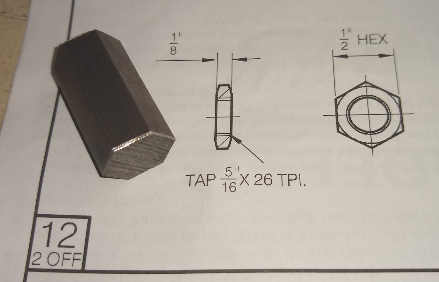
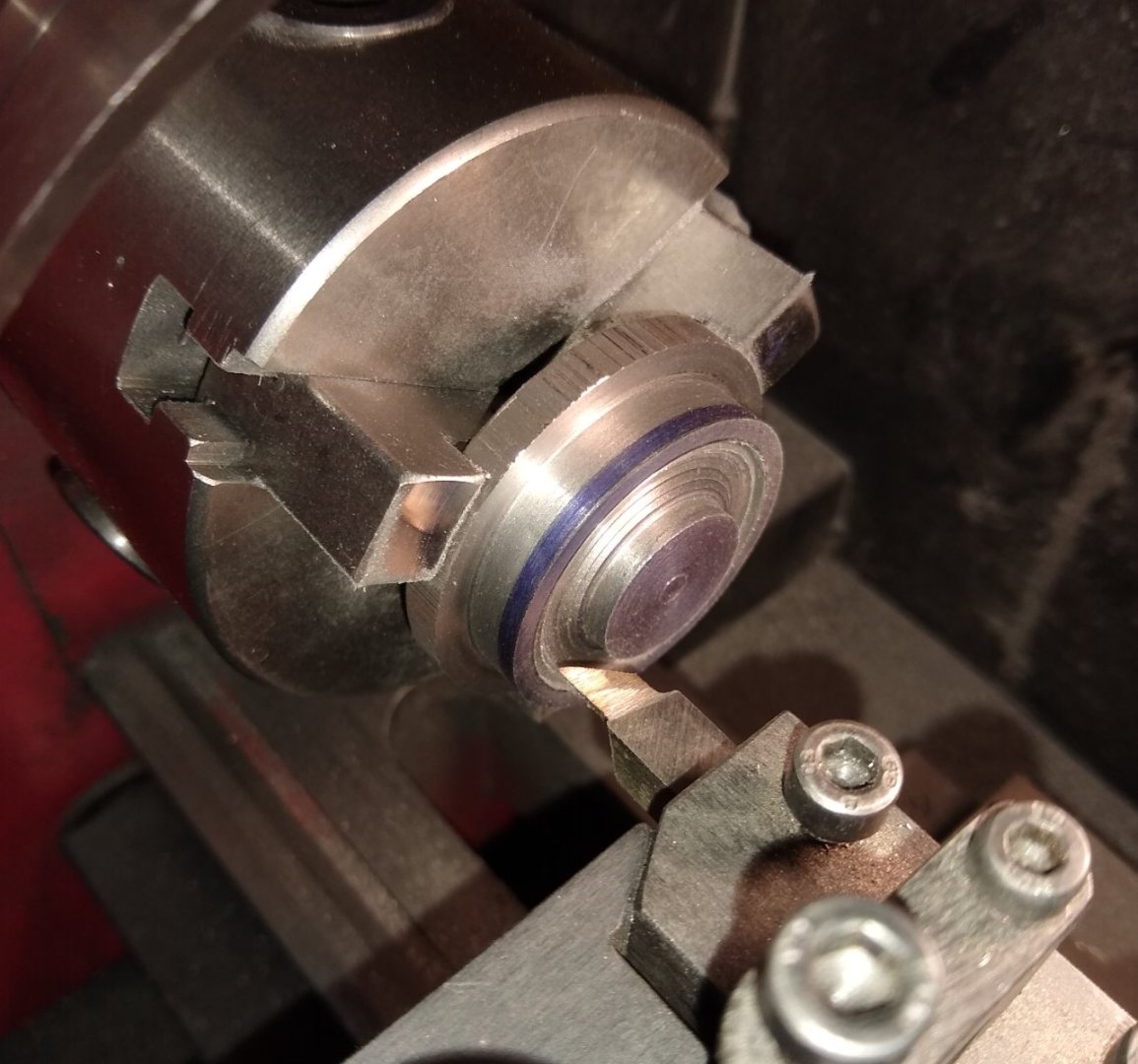
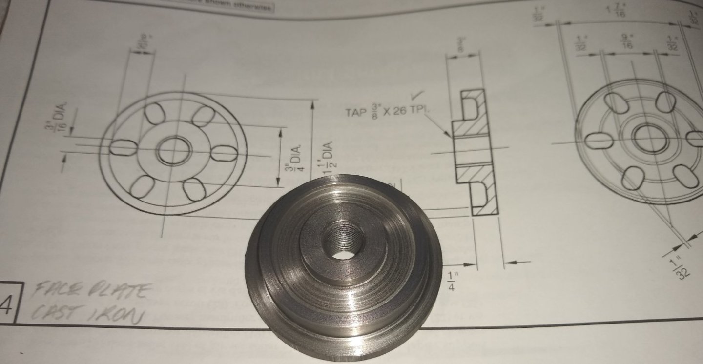
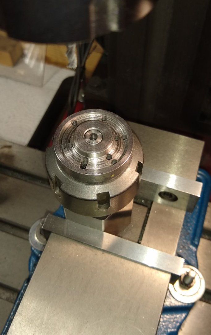
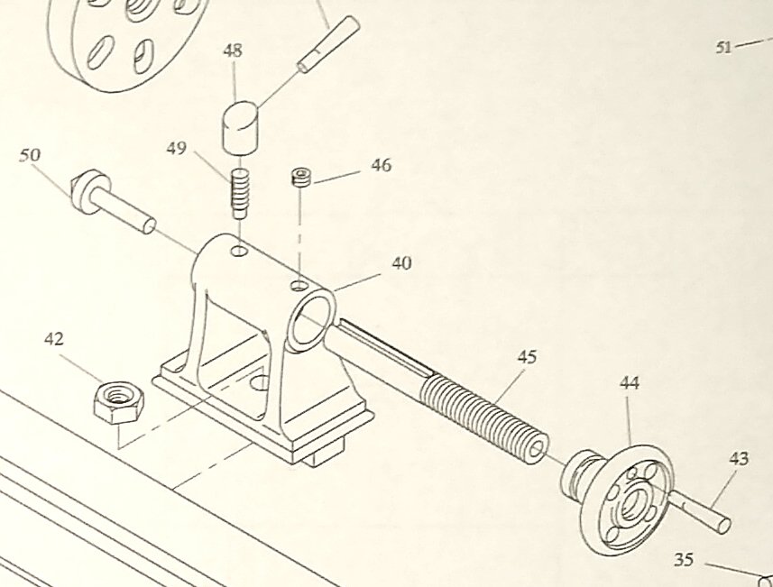
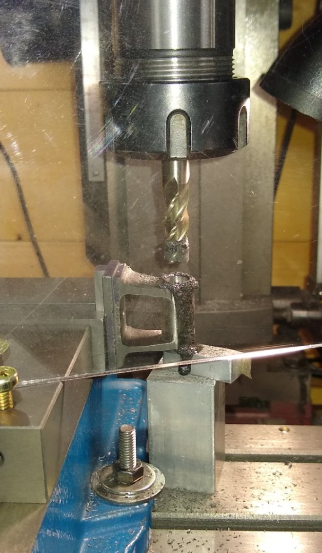
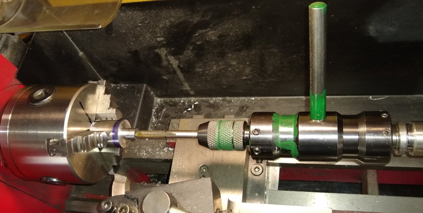
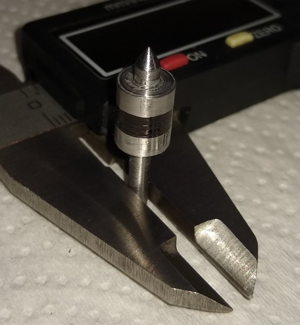
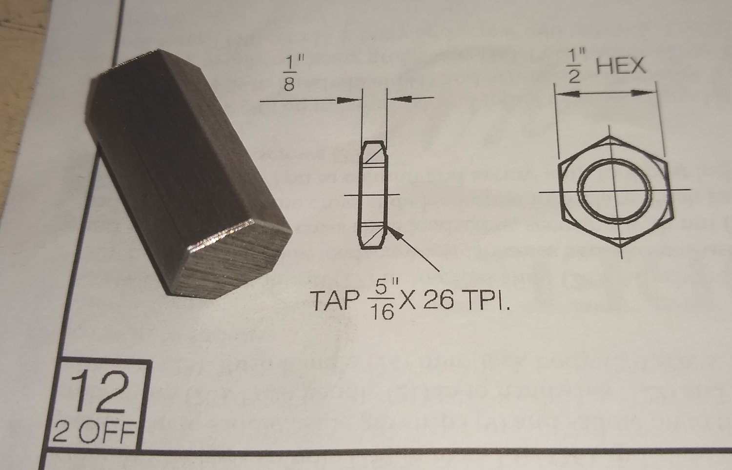
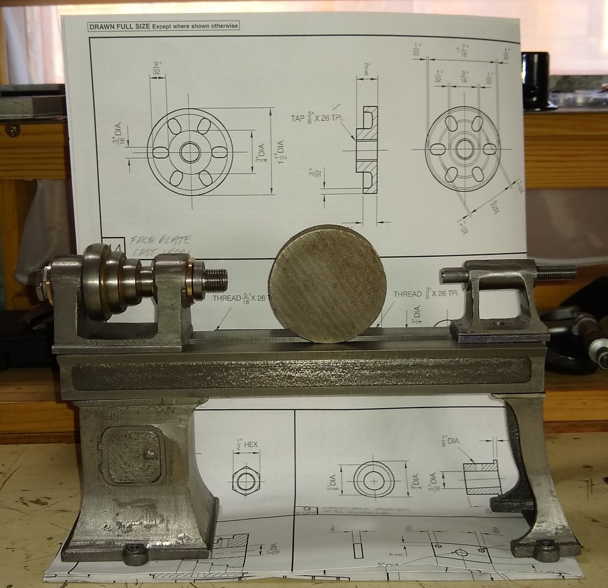
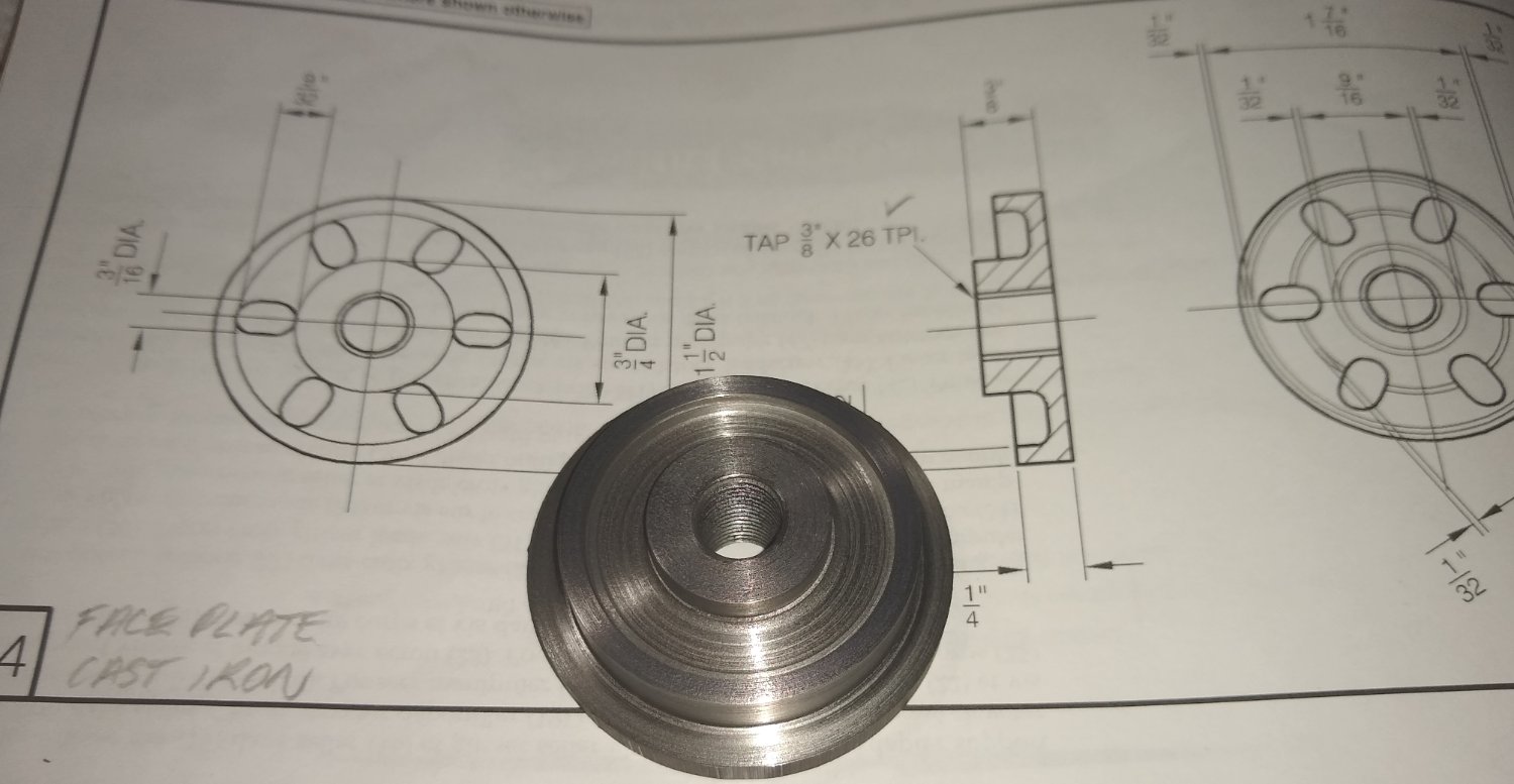
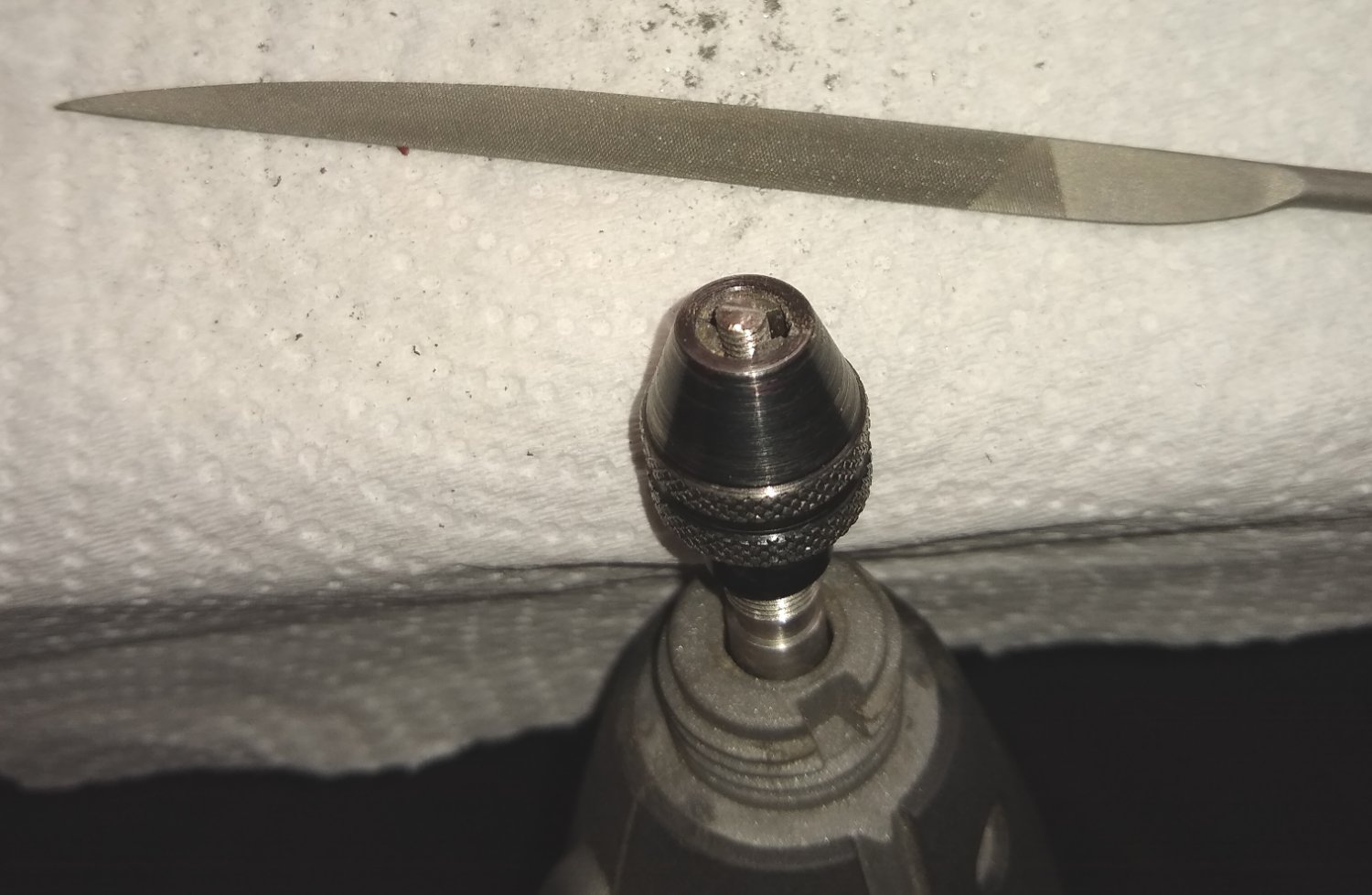
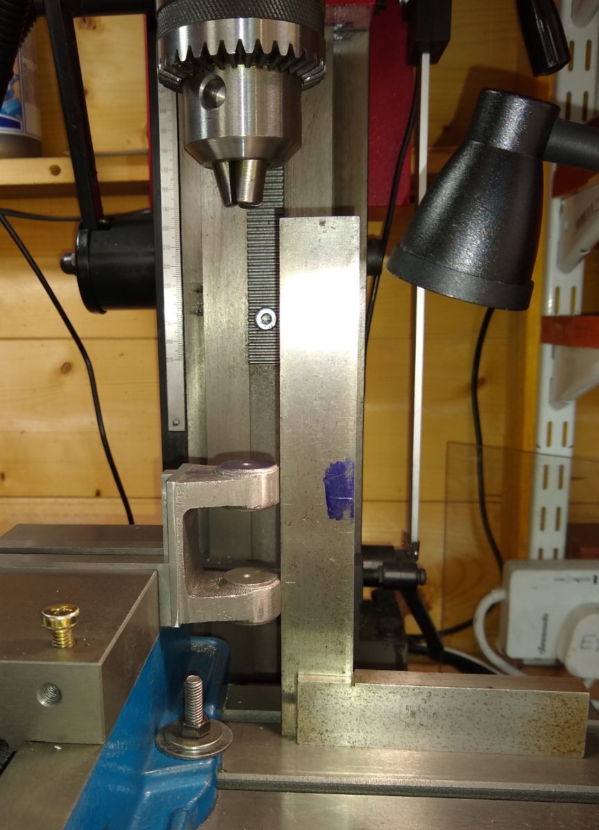
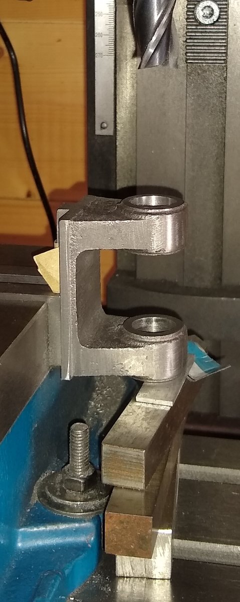
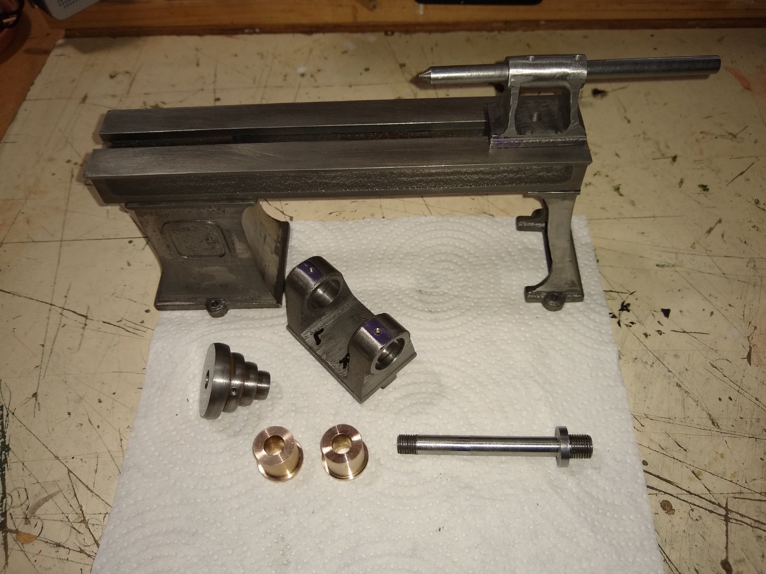
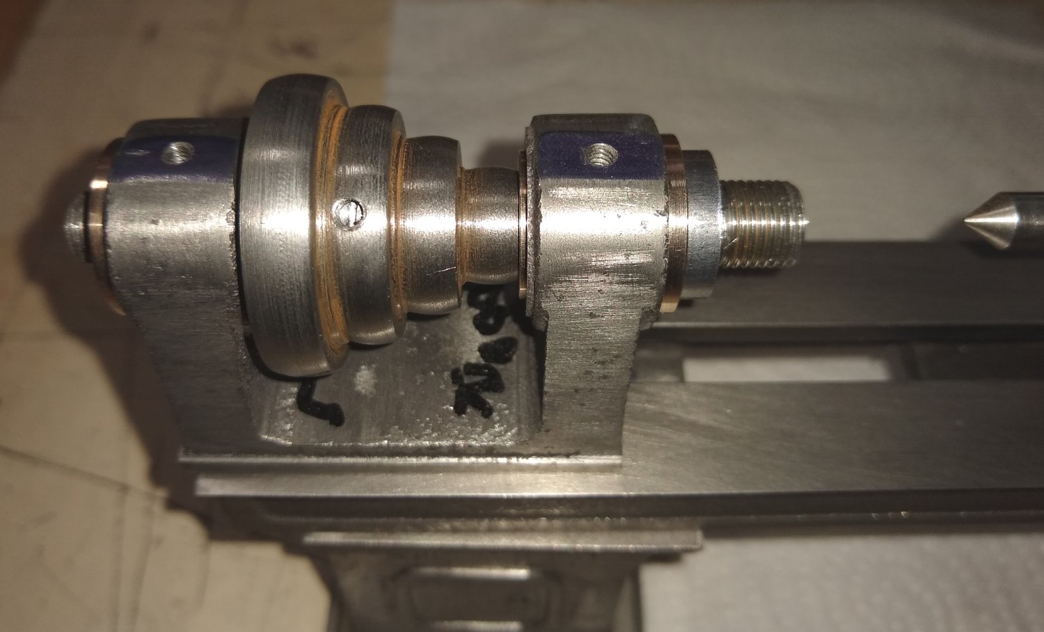
Hi all, Some more pics and info on the lathe build, relating to the Headstock and Tailstock. Below, a reminder of the Headstock parts. This week I firstly I made the two slim nuts (Item 12) that hold the Spindle on the headstock. A piece of 1/2" hex bar is supplied with the kit, and the nut manufacturing process is fairly straightforward. Firstly square off the end, drill and tap the thread, chamfer the nut corners and then part-off. Below, both nuts ready for screwing on to the spindle. The nuts are locked together leaving just enough gap for the spindle assembly to rotate freely. Next, the Faceplate, Item 14. The faceplate is used to securely hold larger and/or more awkward shapes than the chuck can accommodate. Machining one side of the cast iron faceplate. I had used a carbide tipped tool to remove the outer hard skin of the cast iron. Then I reverted to a HSS tool which could be ground into profiles that allowed me to cut in to the recessed corners of the faceplate. Below, one side of the faceplate finished, complete with the through tapped hole. The faceplate drawing shows six radial slots for clamps to use. The drawing slots looked a bit fat and chunky so I made them narrower. Below, the faceplate is held in a mill collet attached to a hexagon Stevenson block. The block is a simple way to index the six locations of the slots. I positioned the block to one end of the vice, sliding it up against a parallel held against the square vice sides. This ensured that every time I rotated the block 60 deg it always was in the same position relative to the milling cutter. I initially drilled two holes for each slot to lessen the workload on the cutter but in hindsight one hole might have been enough. The finished faceplate screwed onto the headstock spindle. Now to the Tailstock. Item 40, the tailstock body had been awaiting the delivery of a 9mm end mill to make a counterbore to accept the wheel end. The drawing called for a 3/8" (9.5 mm) counterbore but that would have left very little meat to tap the 5BA thread (item 46) in to....hence the slightly smaller 9mm cutter. Now on to the tailstock Wheel, item 44. I had to remember that the wheel shaft should be turned to 9 mm diameter rather than the drawings 3/8" (9.5 mm). Below shows the wheel being threaded for the tailstock leadscrew. The tap holder and associated parts have green paint on them to make sure they don't get separated into other tool drawers 🙂 The wheel turned around in the chuck and having the other face machined. Drilling the four holes in the wheel. This time a square Anderson block was used. The tailstock wheel is retained in the headstock by a 5BA grub screw (Item 46) with a small nipple on one end (that locates in a groove on the wheel) whilst the other end has a screwdriver slot filed in to it, with a knife needle file. Below it is shown held in a Dremel chuck - this was quite a handy 'vice' for a small part like this. The Dremel was also used to form the nipple by grinding it's shape with a square needle file. A 'live' centre was also made for the tailstock, Item 50. The drawing shows a fairly basic shaped centre so I tried to make it look a bit more realistically proportioned. A groove being cut in the tailstock leadscrew. Again a screw locates in the groove, this time stopping the leadscrew rotating but allowing it to move in and out as the tailstock wheel is turned. Finally an assembly pic of where we have got to so far. I've sat the tailstock T-Nut on the bed end ...it would normally reside inside the T-slot and clamp the tailstock to the bed. I've still some small parts to add to the tailstock but can include them in a later post. What's next?...well, it's either the Chuck or the Saddle + Cross Slide parts .... I think I might leave the Chuck till last, maybe. Regards, Richard


-
I went with a reamer. Yup, that's what I did, when it eventually arrived by post 😉 Richard
-
Welfalck, Yes, a boring bar is my go-to tool for straight holes. But with the hole diameter being quite small - 5/16" (8 mm), I didn't have a stiff boring bar small enough to fit inside that diameter. I do have some very small diameter home-made boring bars (eg 1/8" dia) but I felt the hole was too deep so the bar would flex, and the Bronze material was already proving quite tough to machine. Yes, it's a fun project and, as you note, enhanced by the generous side-discussions 🙂 Richard
-
Mark, Thanks also to you and EG. You both got me reading up on pulleys and belts and I now know interesting and useful new stuff I didn't know a few days ago 😉 It is quite a fascinating subject, simple as it may appear on the surface....curvatures/angles, belt materials, distance between pulleys, which pulley drives, efficiency etc etc . For example - https://www.plantengineering.com/articles/basics-of-belt-drives/ Richard
-
EG, Thanks for all that ...interesting. Yes, my rounding might be a bit excessive. I can tweak it later. I have a Stuart drive belt and plan to connect the lathe to my Stuart 10V engine and run the two. I'll watch how the belt performs. I think when I was happily filing the curves on my pulley I had a mental picture of my belt linisher's curved pulley ...as I recalled it had quite a curvature but memory plays funny tricks. Thanks again, Richard
-
Hi Mark, Yes, the Pulley has the diameters rounded - I believe this is to help the belt self centre. I rounded the surfaces with careful use of a smooth file and some emery cloth. The pulley on a belt linisher has the same type of curvature. Regards, Richard Edit: Mark, you got me to go and read up on this. So I've learned something new. thanks. It seems that the edge of the belt closest to the crown of the pulley is stretched tighter than the other (slacker) side of the belt. So being tighter bulges towards the crown and therefore pulls itself back to the middle. An explanation with diagrams here .... https://www.tec-science.com/mechanical-power-transmission/belt-drive/why-do-crowned-pulleys-keep-a-flat-belt-on-track/ Any further insights welcome.
-
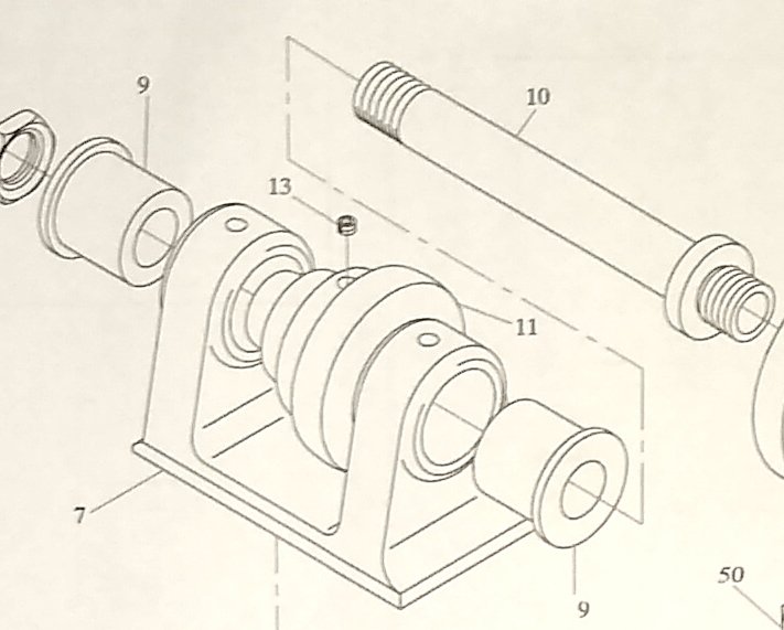
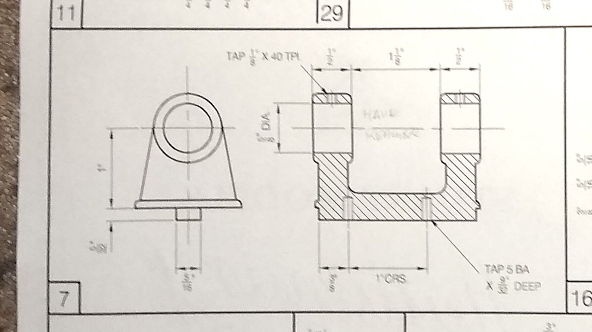
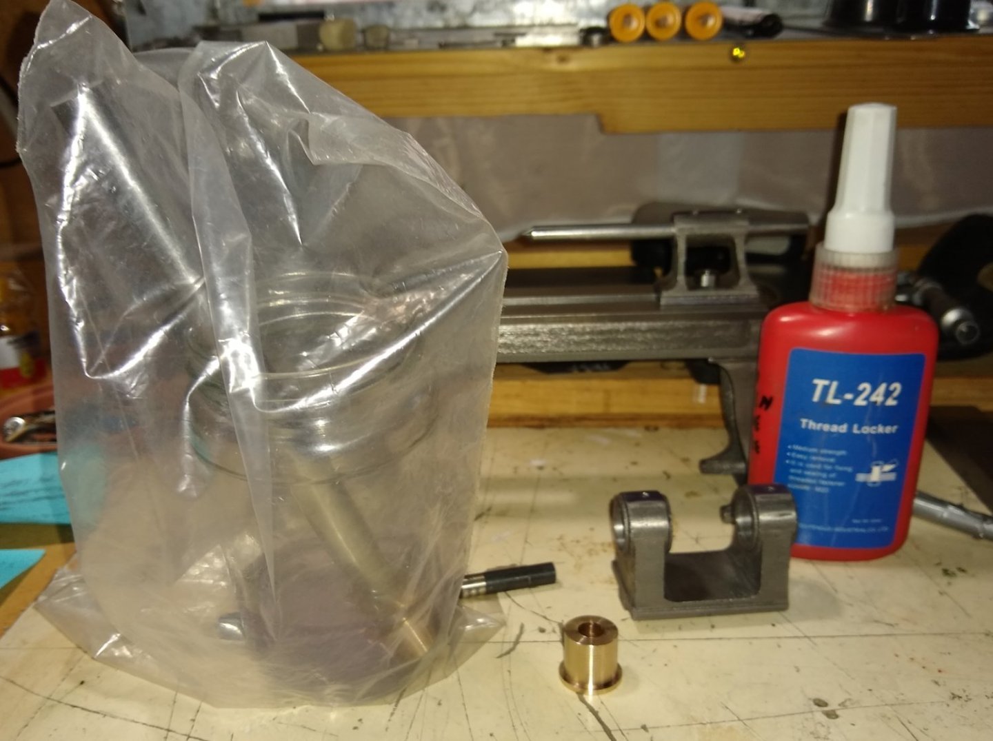
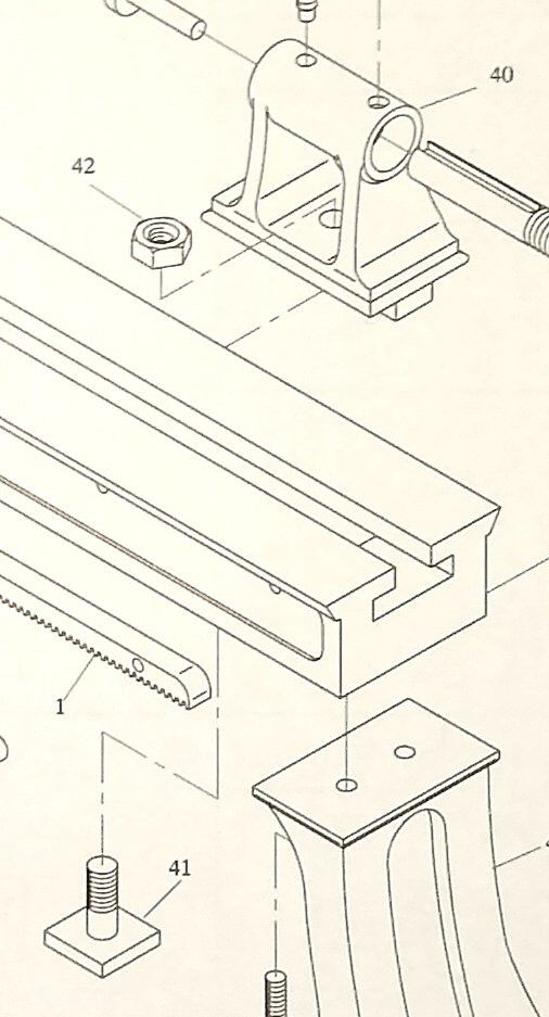
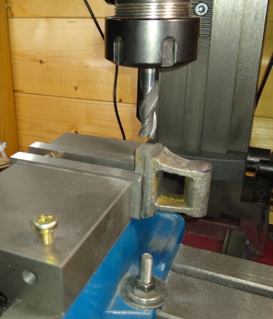
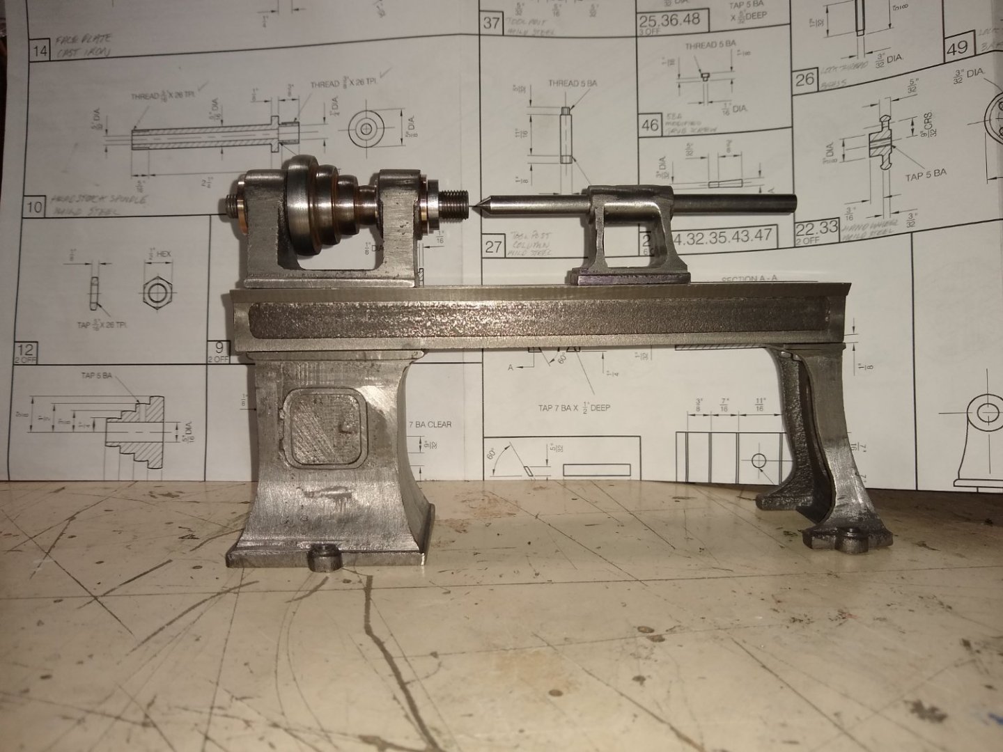
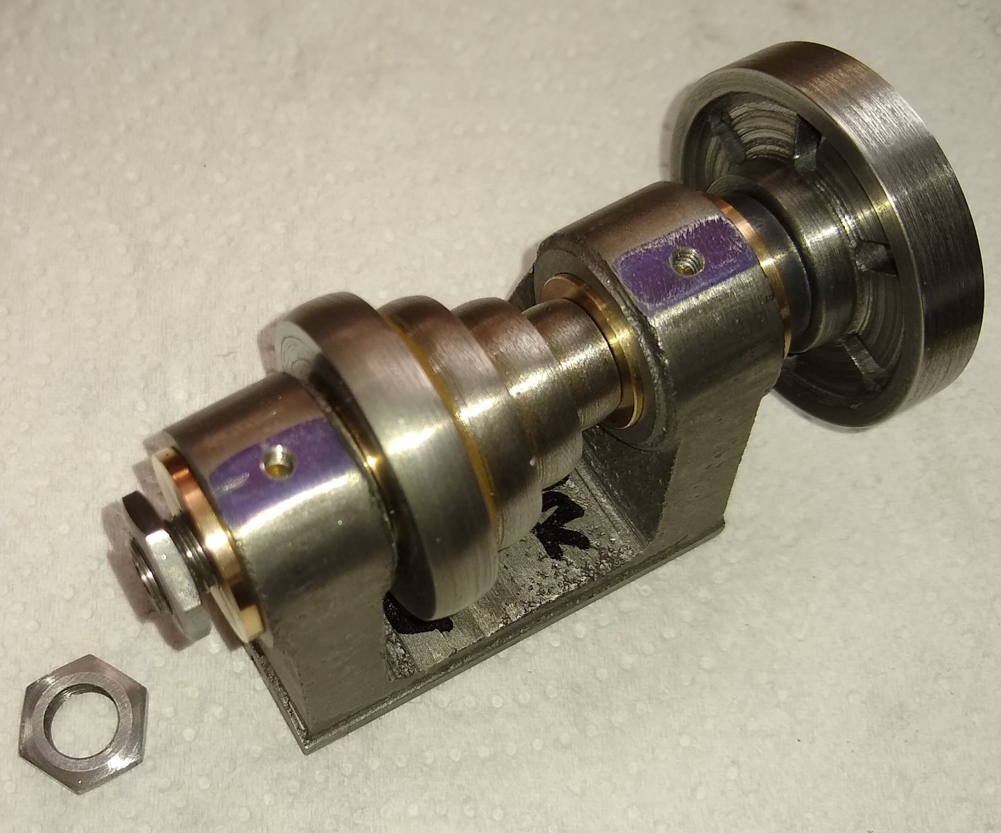
Hi all, After roughing out the cast iron lathe bed and it's 'legs', it was time to have a look at the lathe's cast iron Headstock and Tailstock. Basically, the headstock clamps and rotates the workpiece, whilst the tailstock mostly provides a means of accurately supporting longer workpieces and drilling down the centreline of the workpiece. The headstock is fixed at the left end of the lathe (where it is attached to the motor or belt drive) whilst the tailstock can be slid and clamped at a chosen position along the length of the bed. Below shows an exploded view of the main parts of the headstock. Item 7, the headstock body was first in the queue. So I started with the headstock body itself (7). It is a casting and has no square surfaces. I had to decide what I would use as the reference plane/dimension. This is important since the large holes through the two lobes of the headstock must end up the same height above the lathe bed, parallel with the bed centreline and coaxial with the tailstock. Since there seemed plenty meat on the base of the headstock I decided to machine that first, and if I later found the coaxial holes were too high, say, I could machine more meat of the bottom face. I filed the two longer bottom edges as parallel as I could and then clamped those edges in the vice to mill the tongue that slides in the bed slot. I formed the tailstock tongue the same way. I then gripped that tongue in the end of the vice. Note: The tailstock, with the same width of tongue, is clamped (out of picture) in the other side of the vice to ensure the vice jaws clamp squarely. Above, whilst machining the tongue and it's adjacent faces I also took a light skim off the tops of the two lobes to make the lobe tops parallel with the bottom surface....this allowed me to use a set square to make sure the headstock was at 90 deg to the mill table. Below. I then, after drilling a 6mm hole in both lobes using a stub drill, opened up the lobe holes to finished size using a series of end mills of increasing diameter. Above, I was wary that the mill would exert a strong downward force so packed out the underside of the headstock. Below, that looks like the job is done...so on to the next items, the Bronze bearings 🙂 There are two pieces of (Phosphor) Bronze bushes supplied with the kit. These fit in the lobes of the headstock and allow the headstock Spindle to rotate freely. The raw bush material is not long enough to be supported in a chuck whilst all maching is done, so a 5/16" dia mandrel had to be made. Below. Firstly, a new 6 mm stub drill was gently drilled through each bush, without issue. But once I started to drill close to the finished diameter using normal twist drills they started grabbing the inside of the bush. I wasn't sure what was going on...I tried some lubricant, slowed the drill speed and lowered the force and eventually got through but it was a chore. I believe the Bronze may have been heating up and grapping the drill tip ...also there may have been some galling and burnishing going on inside the hole. Strangely, after the hole was drilled, the 5/16" twist drill could be hand fed through the hole but a 5/16" rod couldn't...I eventually realised the hole was slightly bent in both bushes. The (long awaited) 5/16" reamer eventually arrived and that allowed me to straighten out the holes....and then the 5/16" rod ran smoothly in the holes....phew. Below. Cleaning up the bush exterior faces on the mandrel using a HSS tool without issue. The bush is 'glued' to the mandrel using green thread locker. Above. Using Acetone to get the mandrel out of the bush, once machining was completed. Sometimes a 15 min dip in Acetone is sufficient, sometimes 30 mins in the oven at a high setting is required. I think it depends on the amount of threadlocker applied and the area it covers. It seems a bit of a black art. Below, the Bronze bushes now sitting happily in the headstock and well aligned with the tailstock. Now on to the headstock Pulley - the pulley connects via belt drive to a ceiling mounted, powered pulley.. Again, this is another cast iron part. Below, the pulley is being cleaned up to diameter and length...it had to be turned around and re-clamped in the 3" chuck jaws to complete this machining. There are four stepped diameters on the pulley, to give different belt drive speeds. The picture shows the hole (for the Spindle) being drilled. Again, a mandrel was required to complete the machining. I was probably a bit too generous with the threadlocker this time since (once the machining was finished) I spent about a day trying to get the darned pulley off the mandrel...eventually i put it in the kitchen electric fan oven for 30 mins on a high setting ...it then came off relatively easily. Below, still on the mandrel, waiting for the kitchen oven to warm up. Unfortunately, when removing the well cooked pulley from the well cooked mandrel, the largest pulley diameter got a bit marked...no big deal...I attached it to a makeshift mandrel, then a light filing + emery cloth and all was good. Now the heastock Spindle ie the shaft that runs in the bronze bushes and supports the chucks and faceplate. It was machined in steps, since it is long and spindly. Then held in the lathe's live centre for a final light cut to size. Below, the results of the (few) days efforts ...all keen to be assembled. And a free running headstock assembly is achieved. Still lots of cleaning up of cast surfaces to do but the main machining features are now in place. Yup, there's more 😉 ...the Tailstock. The tailstock followed a similar machining process to the headstock. I've still to put the 3/8" counterbore in the right-hand end .... and I'm not 100% sure how to do that since the barrel of the cast tailstock was way off centre and filing it back central has removed a lot of meat, meaning 3/8" is now too large.So I may have to drop the 3/8" dia to 9mm (...end mill on order). Below, we see the tongue of the tailstock being machined...I tend to use a strip of paper on the clamped surfaces to help even out any surface irregularities. And turned 90 deg to get the through hole milled, similar to the headstock. Shown below is the faces being cleaned up before the holes were added. Almost there 😉 The tailstock is held in position on the lathe bed by a T Clamp.. The first clamp I made was to the drawing dimensions but turned out way too short ...so here I am making anothe clamp with an 1/8" longer threaded portion. And the old T Clamp sitting atop about to be launched into orbit. Finally, a sub-assembly of where I am so far. A lathe shape is beginning to vaguely emerge. Thanks for bearing with me :-.) In spite of some of the issues I encountered, I actually enjoy this stuff....happy days. Regards, Richard


.jpg.9e54c72da63e41c42d7f57c2bf2af440.jpg)
.thumb.jpg.c67233dec4dc540d4e95bae5ca45edad.jpg)

- 74 replies
-
- 11
-
-
Fly cutters, a machinists dream or nightmare. 😉 Fortunately it wasn't a large diameter cut.... or it's wayward cousin the Trepanning tool .... now that's one to keep your eye on! But wait till I get to the bit about machining the Bronze bushes! ... what a weird material. Richard
-
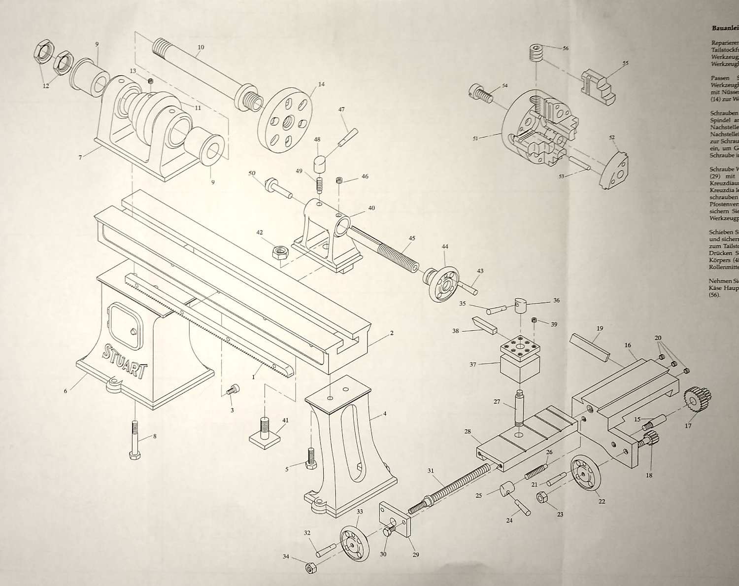
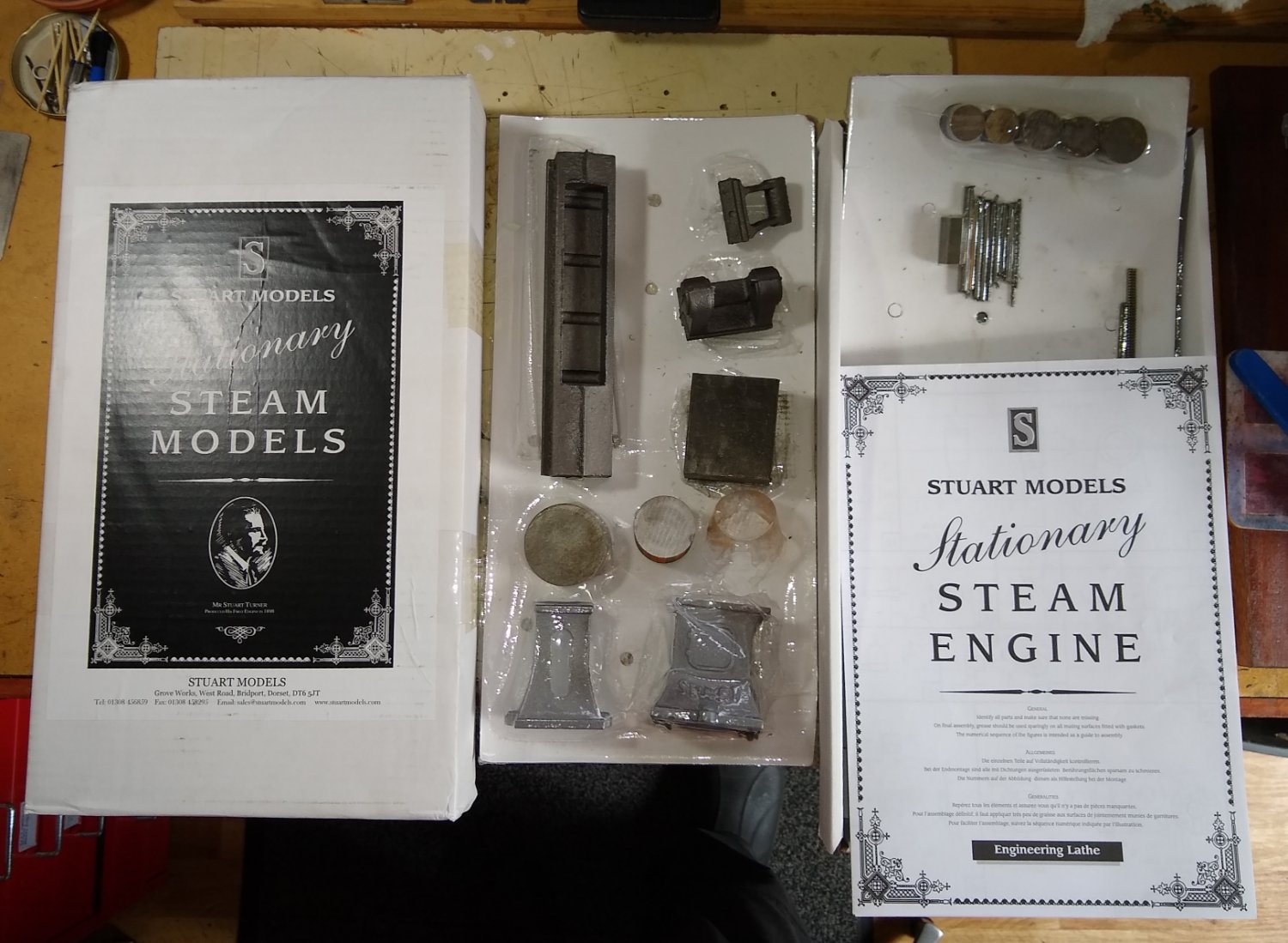
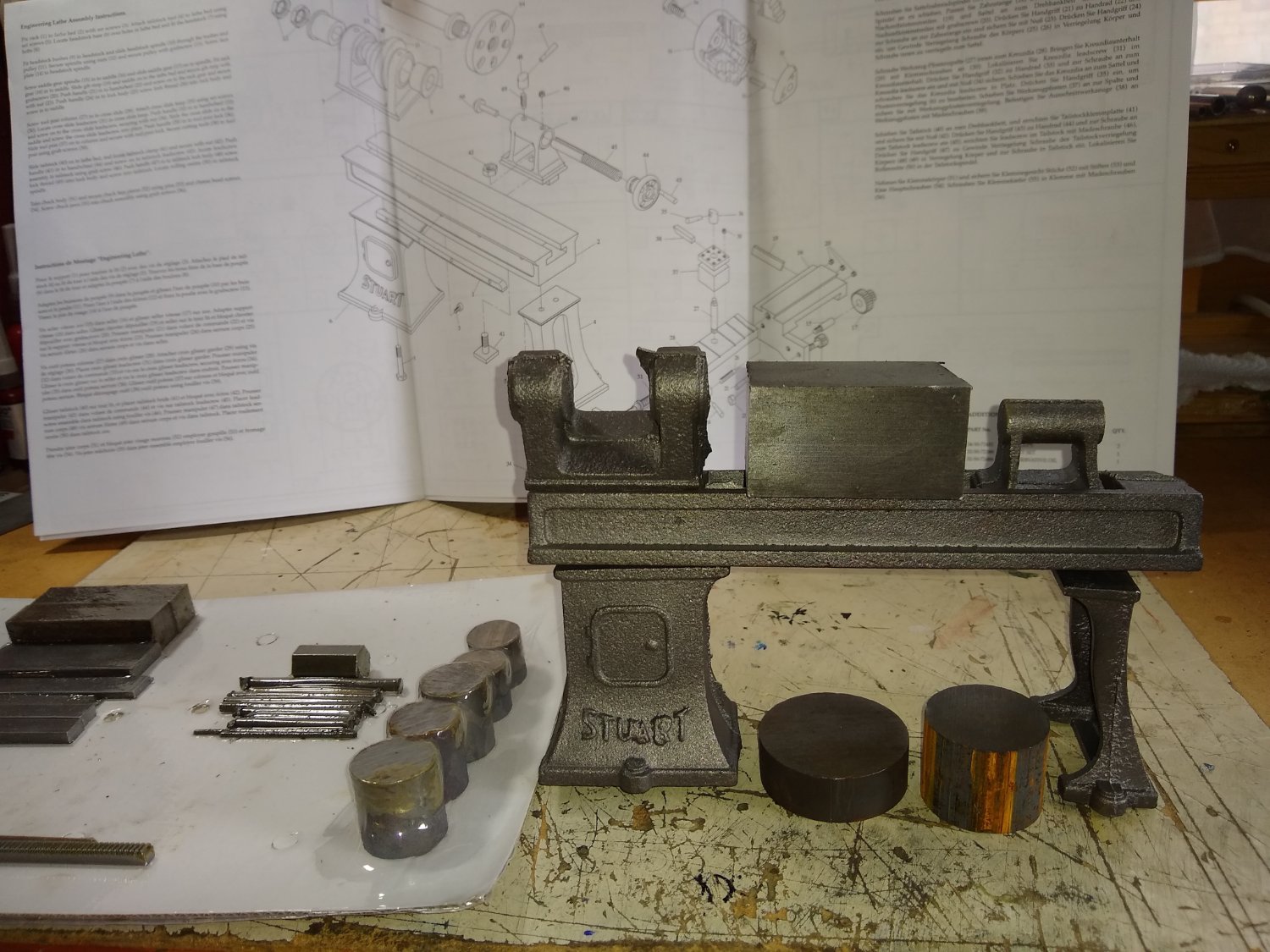
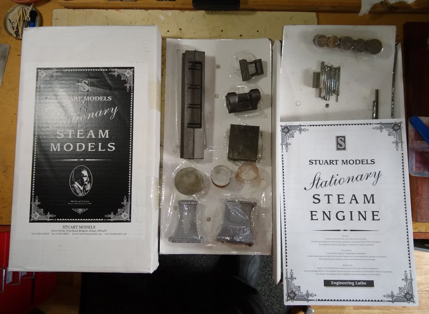
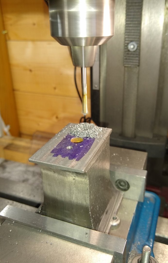
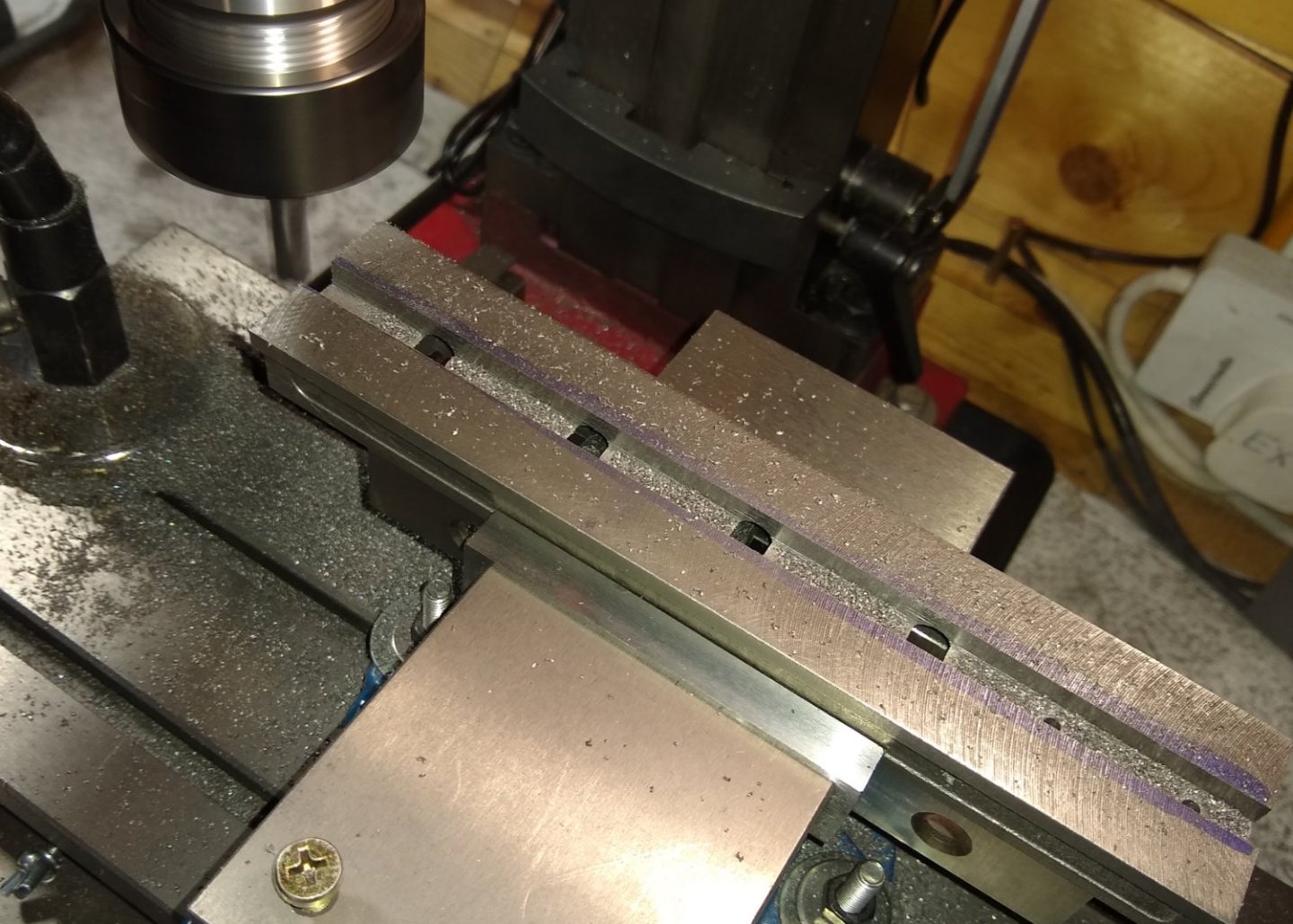
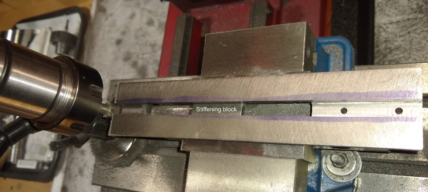
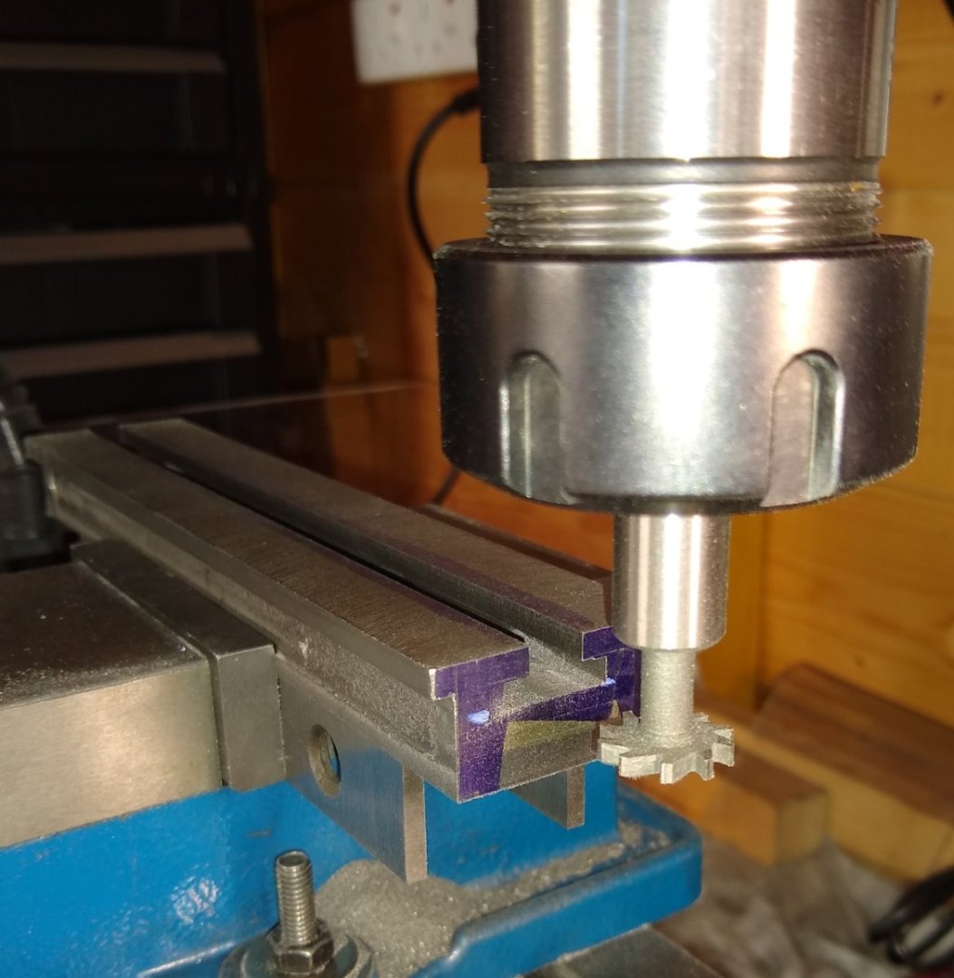
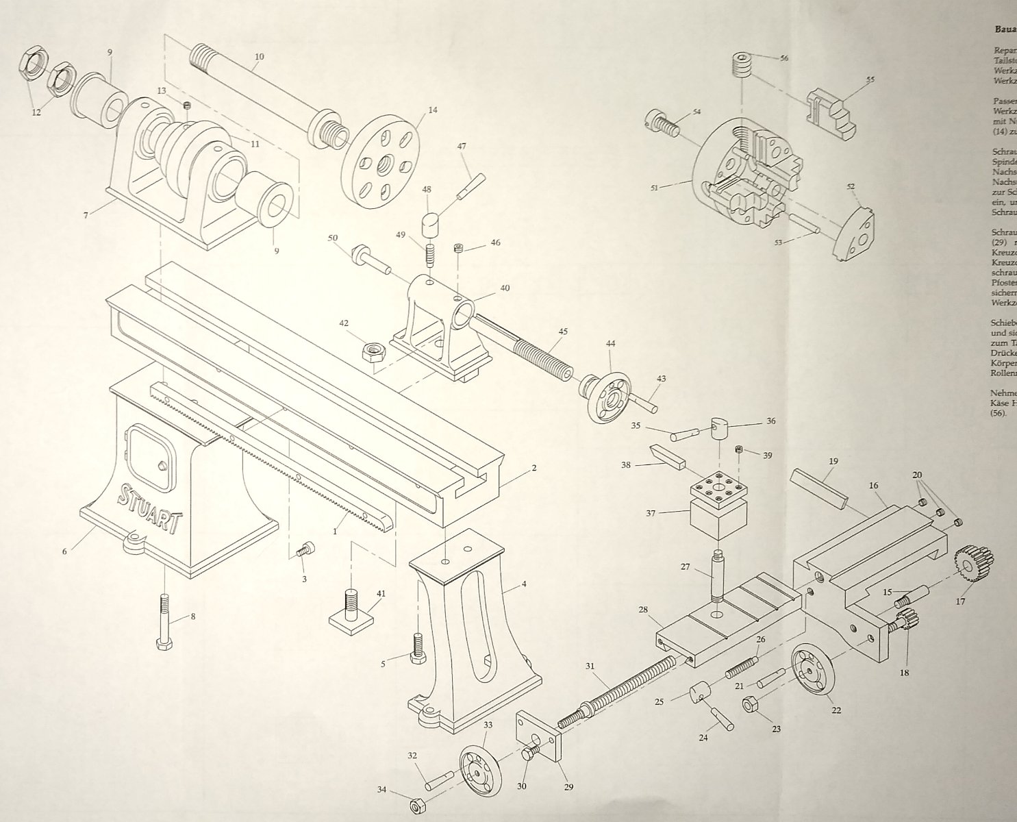
Hi all, This summer I bought the 'Stuart Models Engineering Lathe - unmachined' as a short project to tide me through to winter .... https://www.stuartmodels.com/product/stuart-engineering-lathe-unmachined/ I started on it a few weeks ago so haven't yet completed it and will post updates as I pass the build milestones. Not surprisingly I'm using a lathe to build the lathe, and a milling machine. Below is the lathe's exploded diagram supplied as part of the instruction set. At first look it seems a bit simpler than the Stuart Beam Steam Engine build, say, but it isn't without it's own challenges and head-scratching moments. Below - As usual, everything arrives in the rigid Stuart cardboard box. And here is a quick 'lathe assembly' of the larger parts, next to the other materials and the instruction sheet. The big square metal lump sitting in the middle of the lathe bed is Item 16, the lathe Saddle ... I'm guessing it will mostly end up as a slim elegant item and a big pile of swarf! Above. As usual, the larger parts are made of cast iron so will require grinding/filing to remove the casting flash and to introduce the beginnings of 'squareness'. Squareness will be quite important since it has a direct effect on 'work holding' in the mill vice or lathe chuck(s). And, as also usual with these items, the question of what surface(s) to use as the initial reference plane raises it's head. I'm not sure if there is a definitive answer to that one since it can depend on the machinist's ability and the machinery available. Anyway, my strategy with these builds tends to be to rough out the larger parts first and take it from there. Below, the lathe bed sitting on Headstock Base and Tailstock Foot. The bed had had it's top and bottom surfaces milled flat using a 10mm diameter cutter. This involved a lot of winding the mill bed backwards and forwards - there must be a better way 😉 Below, the Tailstock Foot being clamped to the mill bed - this surface would then be used to reference the bottom surface from so that both were square and parallel. Below, and the milling begins. I'd Blue'd the surface to give me a sanity check on how much material I needed to remove. And talking of sanity, I thought (for a tiny fraction of a second) that this 'work holding' might work to allow me to mill the top face. It did allow me to use the bottom face as a reference but there wasn't too much else to be said of that idea. So back to clamping on the mill bed. Setting up the squareness was a bit more difficult but clamping was way more secure and safe. Once both the Tailstock Foot and Headstock Base had had their two main surfaces milled flat and parallel to each other, it was on to drilling holes for attaching to the lathe bed and a clearance hole for the Tailstock Clamp (Item 41). After having wound the mill table up and down countless times on these sort of projects I knew it really was time for me to buy a Flycutter. As opposed to an end mill, a flycutter is a single point cutting tool but covers a much wider swathe. The finish was quite rough - I was moving the table too quickly and taking too deep a cut - but I later smoothed the lathe bed top surface to a better finish using a draw file and emery on a surface plate. Now to cut the central slot in the lathe bed that the Headstock and Tailstock will locate in to. This was reasonably straight forward. However, as I cut the slot deeper it dawned on me that I was removing the material that the vice was clamping against. I needed to put in a temporary spacer to stop the vice pressure collapsing the sides of the lathe bed. The stiffening block spacer was held in position with a strip of double-sided sticky tape. Top view of the lathe bed and the stiffening block. Now on to some fun stuff. The lathe bed has a T-slot cut in it to accommodate the Clamp for the Tailstock, and the slot runs the full length of the lathe bed. Sourcing a cost effective (ie cheap) T-slot cutter wasn't straightforward - good quality ones of the exact size seem to start at around £40 and head upwards rapidly. I eventually managed to find two cheaper ones of different sizes, the smaller size to rough out the slot and the larger diameter one to finish the slot off. Finally another cutter was procured to cut the 60 degree angle of the sides of the lathe bed. That worked OK. A keen eye will notice that the T-slot has a small step on it's top surface ... the mill operator wasn't paying attention! This can be remedied at his leisure 🙂 Well, I think that's it for today. The Stuart lathe has been a good buy, with the usual caveats eg the cast iron parts still suffer from glass hard corners and surfaces where rapid cooling occurred, and some cast items are almost at their finished dimension even before machining has started, but all-in-all I'm pretty happy so far. See you soon. Regards, Richard


- 74 replies
-
- 16
-
-

-
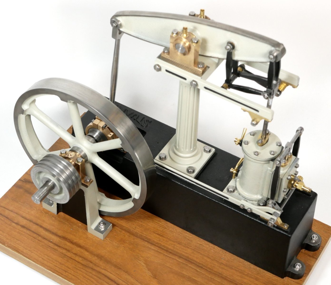
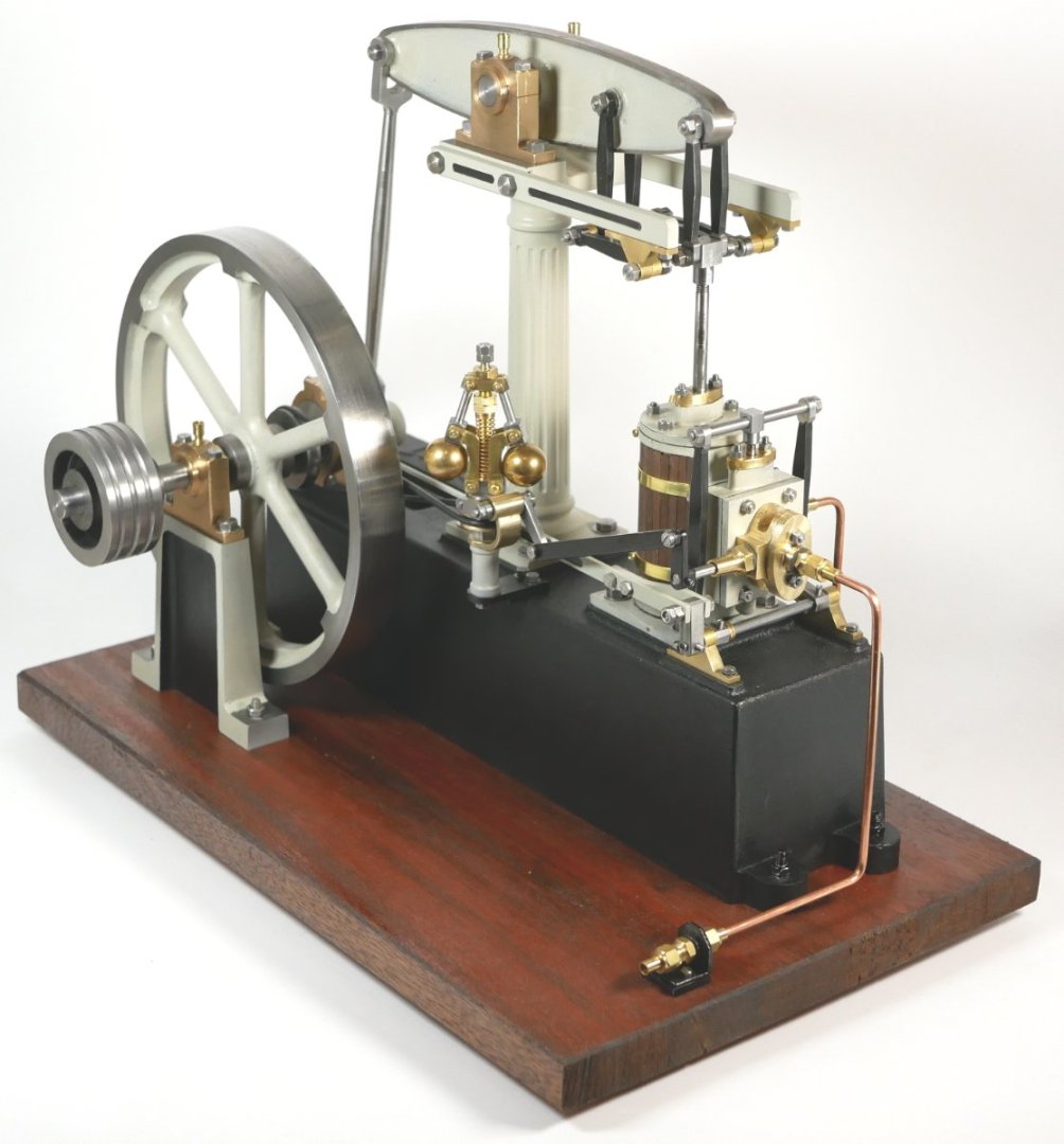
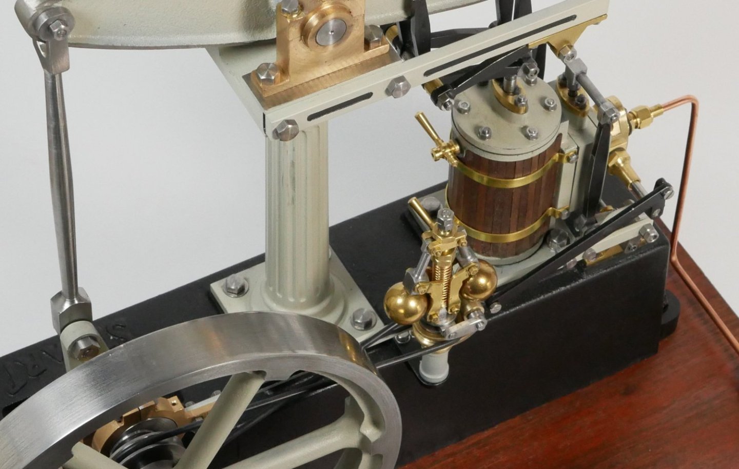
Hi all, A couple of final pics to close off the build thread. I've added the Governor mechanism, lagged the cylinder and attached copper (Inlet and Exhaust) pipe work. But still in the process of setting the timing etc. The Governor build went reasonably well, although with hindsight I may have built some of the parts differently from the Drawings...next time! The Governor connects, via a linkage, to the Inlet at the front of the Cylinder and controls flow by a throttle type flap. There is some debate as to whether these governors actually work properly at model level, and even at full size level where they may in fact only be a safety feature in case the belt drive snaps.... any thoughts welcome. The cladding, like the fluting on the column, IMO adds that bit extra to the build. I used spare wood from one of my model ships and brass banding from a UK supplier. If anyone fancies building one of these steam engines feel free to ask me any questions here. And/or visit https://www.model-engineer.co.uk/forums/, https://www.modelenginemaker.com/ etc for great examples on top notch steam engine builds. I'm not sure what my next build will be - steam engine, model ship or HMS Flirt 😉 ...time will tell. See you all soon, Richard [Edit: Timing is sorted so the Beam Engine now runs very smoothly and peacefully ;-). I've also bought the Stuart Engineering Lathe model as my next project.... watch this space]
- 72 replies
-
- 16
-
-
-
Woodepgh, I wish you luck ! As I mentioned in the thread there were a couple of decades between me starting the Dallas build (completing the hull, deck etc) ...and then digging it out of the attic and completing the ship (masts, rigging etc) ... this seems to be a fairly common phenomenon 😉 When restarting, it took me a few weeks to get up to speed again with the instructions ... which, as you say, aren't the clearest. The drawings were OK though, but sometimes did require close examination with a loupe to eke out the tiny details. Regards, Richard
-
John, Thanks. Collins is a respected name in the Avionics business....I worked in that area for a few years. I have a friend who designed and marketed an amateur radio Transceiver with a ridiculously low oscillator drift. It's a fascinating and deep subject. Richard
-
wefalck, Thank you for the detailed insight. It's an interesting subject in it's own right. I remember the London workshop I did my training in during the 1970s having a 'paint weekend' where all the machines were to be given a fresh coat of paint - volunteers required. There was some debate leading up to this weekend regarding sourcing the paint and colour choice. It had been a number of years since they were last painted so availability and fashions had changed. IIRC, we ended up using a Sky Blue paint with a hint of green in it ... this may have been similar to the Sea Foam Green referred to in the above link. After thoroughly cleaning the machines down and disassembling some, a (very ) thick coat was applied. Richard
-
Wefalck got me thinking and then reading about paint colours for machinery. It may be that 19th century Beam engines were originally painted black, and as time went by and new colours became available (as well as the machinery needing a fresh coat due to wear) other colours were painted over the original black. This American forum thread has a number of interesting opinions on the subject ... 'Any idea of original factory colors of machines?' - https://www.practicalmachinist.com/forum/threads/any-idea-of-original-factory-colors-of-machines.279746/ Extract - The development of paints had some bearing on the colors machine tools were painted. In the late 1800's-early 1900's, a lot of paint was hand mixed by the person doing the painting. Linseed oil, Japan drier, and a pigment, perhaps thinned with turpentine. House paint was pigmented with white lead. Black paint got lamp black for pigment. Not too many color choices, as it were. Colors varied slightly from one batch of paint to the next. Black was predictable, while gray was going to vary from one batch to the next. I think that battleship gray came into use when it became commercially available in consistent color from one batch to the next. Battleship gray probably came into use as it made for a lighter shop in an era when shops were notoriously dark. Relying on natural light filtered through a jungle of belts, with dirty window panes and minimal artificial lighting, and dirt and grunge from the lineshafting (leather particles mixed with oil from the lineshaft hanger boxes got all over the shop), and black machine tools, the shops were dark places. Battleship gray paint had a psychological edge to it, as it was the era of the Dreadnought or the heavy battleships. I am guessing the gray paint took over some time around WWI. Richard
-
Thanks Rob, It was a bit of a retrospective build log since I already had all the pictures taken and the build complete. I'm now realising it is simpler posting each stage of a build as it happens, rather than trying to construct a timeline after the build is complete 😉 I did keep regular downloads of the pics in dated folders on my computer and written notes, but it's surprising how much I rely on using fresh memories to make sure I don't miss something when doing an actual 'live build' as opposed to this build. regards, Richard Edit: And thanks Wefalck ...I could have easily doubled the length of the build, but at the back of mind always was 'remember, this is a model ship building forum' so didn't want to overdo it. Good point about the darker colours. Also, I think I read somewhere that 'green' was the more easily available colour in those days, for what ever reason.
-
Roger, Egilman, True that! Sorry Rik.... It's OK 🙂 It's the end of the build log anyway, and it's always interesting to read information about all branches of engineering/technology and reports from the coal face. Richard
-
Hi Ian, Thank you. Yes the Clyde was at one time a hot bed of ship building and other industries. Yarrow still does work there, I believe ... I've been on a number of their frigates around the world, but not as a service person. And a toolmaking apprenticeship at RR would be a feather in one's cap...still is. cleaner Back in the day 'engineering' may have been seen as a less promising career by those who didn't know it, but in my book it is the prosperous foundation on which most of a country is built. These days engineering, like most prefessions, relies heavily on computers etc .... but there is absolutely no substitute for hands-on experience to complement the 'higher-tech' skills. Richard
-
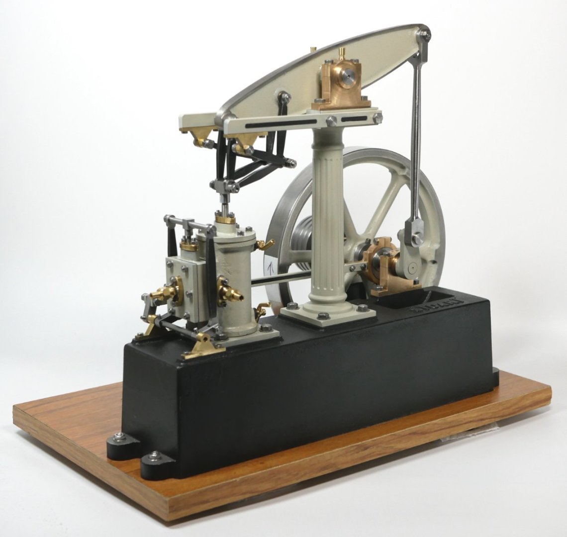
Final assembly, test and painting. The engine was piece-meal assembled as finished parts became available. Once enough were available I connected a cordless drill to the end of the crankshaft and powered it up to get a general feel for how well it would (or wouldn't) function - all seemed OK. Before painting I did a full assembly, had an initial attempt at setting the timing and then applied compressed air to the Steam-In port on the front of the Cylinder. There was little or no movement, so I tweaked the timing...now it moved hesitantly but required about 40 psi - far too much! After a day or more of further tweaking I could get the engine to run very smoothly at 1 psi, according to the pressure gauge. These gauges are not accurate on the first 15-20 % of their scales so I'll call it 5psi and a very satisfactory result. Whilst I had been building the Beam engine I had been researching other's build and the paint schemes they chose. Traditionally the full sized engines were painted mainly green with red highlights. I wasn't too keen on that scheme since, although accurate, I felt something a bit 'different' but still industrial looking was required. So I ended up choosing PlastiKote Satin Black and Satin Warm Grey - results below. The current wooden base is only temporary. I may add a Stuart models Engineering lathe (https://www.stuartmodels.com/product/stuart-engineering-lathe-unmachined/ ) so a larger piece of wood will be required. (Edit: On 2nd thoughts a lathe would be inappropriate for a Beam engine - it would be more suited for the 10V). Close-up. View from the other side. Finally, my 6" high Stuart 10V with a 3" diameter flywheel next to the Beam engine with it's 7" flywheel. It was a fun build with a good bit of puzzle solving helping keep the grey matter in shape. I started it in April and finished towards the end of July, doing a little bit most days. I'm currently building the Governor for the Beam engine so will add a picture of that on the Beam when the time comes. Thanks for all the Likes etc and the interesting side-discussions on related topics 😉 All for now, Richard


- 72 replies
-
- 12
-

-
-
-
Mark, Egilman, Interesting stuff, thanks. downforce created actually slows the car by about 20% I always wondered what the actual effect of downforce was on all-out speed. From the little I know about F1 design I believe that downforce pays dividends in cornering ability though. From https://en.wikipedia.org/wiki/Stanley_Motor_Carriage_Company it would seem that the Stanley brothers eventually had an unbeatable competitor at 25% of the price and with instant start. Richard


.jpg.ca49a73194a732db35da6b479f23d0b2.jpg)