


AnobiumPunctatum
-
Posts
1,267 -
Joined
-
Last visited
Reputation Activity
-

 AnobiumPunctatum got a reaction from mtaylor in Mercury by SimonV - Amati/Victory Models - Scale 1:64 - 99% scratchbuild
Really nice carvings, Simon
-
 AnobiumPunctatum got a reaction from SimonV in Mercury by SimonV - Amati/Victory Models - Scale 1:64 - 99% scratchbuild
Really nice carvings, Simon
-
AnobiumPunctatum reacted to SimonV in Mercury by SimonV - Amati/Victory Models - Scale 1:64 - 99% scratchbuild
My First attempts in carving... . Very enjoyable but slow work, with pleasing results .
At first I was thinking to make 3D models and complete them on CNC milling machine, but investment would be too high for now. So, everything will be hand made.
-
AnobiumPunctatum reacted to SimonV in Mercury by SimonV - Amati/Victory Models - Scale 1:64 - 99% scratchbuild
Almost there ... currently working on garboard plank and keel .
-
 AnobiumPunctatum got a reaction from Nirvana in Mercury by SimonV - Amati/Victory Models - Scale 1:64 - 99% scratchbuild
Simon,
very nice build.
If you cut the parts of the components for the stem, you have to look to the grain of the wood. It should be always in the longitudinal direction of the part and not perpendicular as seen on your stem. Take this for the future and don't changeit on your model, after coppering not much will be seen from this.
-
-
 AnobiumPunctatum got a reaction from KennyH78 in H.M.S Triton Cross Section by KennyH78 - FINISHED - 1:48
It's looking great, Kenny.
-
AnobiumPunctatum reacted to archjofo in La Créole 1827 by archjofo - Scale 1/48 - French corvette
Hi Nils,
thank you for your nice reply.
And this is how the result looks.
-
AnobiumPunctatum reacted to cabrapente in L'Amarante 1749 by giampieroricci - FINISHED - 1:30 - French Corvette
Hola, ¿de dónde sacas esas grandes monedas?
-
 AnobiumPunctatum got a reaction from Canute in H.M.S Triton Cross Section by KennyH78 - FINISHED - 1:48
It's looking great, Kenny.
-
AnobiumPunctatum got a reaction from Canute in H.M.S. Triton Cross Section by Ainars Apalais - 1:48
Looks good. The redesign of the gun port sills is not necessary. The joints are very stable. If you want to make the joints stronger, you can use some tree nails
-
AnobiumPunctatum got a reaction from mtaylor in H.M.S Triton Cross Section by KennyH78 - FINISHED - 1:48
It's looking great, Kenny.
-
AnobiumPunctatum reacted to KennyH78 in H.M.S Triton Cross Section by KennyH78 - FINISHED - 1:48
Got a little more work done in the shipyard today. Finished up the grate for the after hatch and the stair ladder for the forward hatch. I installed the hatch coamings and the grate and the stair ladder. I still need to apply some wipe on poly finish. Next up is the top sail bitt. I also need to make some rope and rig up the guns. Enjoy the pics and any and all comments/critiques are welcome.
-
AnobiumPunctatum reacted to woodrat in Venetian Carrack or Cocha by woodrat - FINISHED - 1/64
I do apologize for my tardiness in updating this log. I have been in the process of restructuring my professional committments and, consequently, have neglected the more enjoyable of my pursuits. I have, however, finally worked out the likely method that was used to laterally stabilize the mainmast. The shrouds are passed inboard, not as in later vessels outboard to chainplates. The pendants from the mainmasts ( more later) are secured by tackles. This is more in keeping with the iconography of the period in mediterranean vessels. It may well have been different in the northern european vessels as illustrated by the drawings by the flemish master WA, which show chainplates. Certainly it would have been vastly simpler for me to secure the pendants outboard but, in shipmodelling, it is sometimes better to aim for accuracy rather than facility. Nonetheless, I offer this as a solution which is consistent with the scanty evidence.
Dick
-
 AnobiumPunctatum got a reaction from Elijah in HMS Atalanta 1775 by tlevine - FINISHED - 1:48 scale - from TFFM plans
Wonderful result, Tony
-
AnobiumPunctatum got a reaction from mtaylor in H.M.S. Triton Cross Section by Ainars Apalais - 1:48
Looks good. The redesign of the gun port sills is not necessary. The joints are very stable. If you want to make the joints stronger, you can use some tree nails
-
AnobiumPunctatum reacted to tkay11 in NAIAD II, Ed Tosti (Moved by moderator)
Thanks, Ed. The two volumes are already with me and I've been studying them. They're helpful not only for what I'm doing now, but will certainly be of use for my next model (probably Le Rochefort) and then, quite probably, the Naiad.
Tony
-
AnobiumPunctatum reacted to Ainars Apalais in H.M.S. Triton Cross Section by Ainars Apalais - 1:48
Hello everyone.
Decided to slightly update my work.
I made Tree nails for frames
.
Clean all the paper. And recommendation of using Fixo gum glue had perfect.
Before assembling cut out recess for gun ports.
And finally start assembling frames.
I slightly redesigned Gun port sill. To create more stringent joint.
At the moment it would all.
But to be continued.
-
AnobiumPunctatum got a reaction from mtaylor in HMS Atalanta 1775 by tlevine - FINISHED - 1:48 scale - from TFFM plans
Wonderful result, Tony
-
AnobiumPunctatum reacted to Baker in Golden Hind (ex-Pelican) by Baker - FINISHED - scale 1/45 - Galleon late 16th century
Hello
The upper ends of the frames are provided with supports.
So that they can be less easily damaged.
I started with the filling of the lower space of the frames ( i think "fillerbloks" is the correct word).
Wooden pieces are sawn to length.
These pieces are then made at approximately the right shape.
And glued between the frames
A few frames also had to be adjusted.
One side is filled up, and can be sanded.
One side is sanded
I used this machine to sand the rough shape
Some test planking is attached (looks ok)
The frame of the stern has been modified and should now have better shape (thanks druxey).
One side is done and seems to have the proper shape below the waterline
One side to go.
Ps,
I had picture uploade problems, see :
http://modelshipworld.com/index.php?/topic/15445-images-size-fixed-at-12-px/
Groetjes
Greetings
-
AnobiumPunctatum reacted to EdT in Young America 1853 by EdT - FINISHED - extreme clipper
Young America - extreme clipper 1853
Part 198 – Making Futtock Shrouds
The lower futtock shrouds on the fore and main masts are 5 1/4" rope (meaning the circumference is 5 1/4"). This equates to a rope diameter of about 1 ¾", about .024" at 1:72 scale. The mizzen shrouds will be 4 ½".
I used rope made from three strands of (.012" dia.) Barbour Irish linen suture thread for this. I hope to use linen for all of the standing rigging – if the sizes I have will work out and if my limited inventory of quality linen holds out. I like the hardness of the linen and its resistance to stretching for the taut standing rigging, but quality has deteriorated in recent years. I will forgo a discussion of rope making and sizing here, but expect to fully describe the process that I use in Volume III. Rope making methods and hardware have been well described in many sources. I find it to be more of an art than a science that can be described simply.
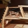
I will instead start with the serving process. I made my serving machine ten or twelve years ago for my Victory model. It is shown, with some modifications since then, in the first picture.
The machine consists of large crank-driven gears at each end connected with a jack-shaft as shown. These gears drive smaller spur gears in synchronization and at stepped up rpm. Rope is stretched between tubular shafts through the smaller gears. The next picture shows one of the crude collets that hold the rope.
The rope passes through the tubular shaft, allowing long lengths to be fed through at the length needed. The picture shows the method I use to start the serving thread. A needle is passed between the strands and the thread pulled through. The thread used here is Guterman quilting cotton, a long-staple, fine cotton thread with virtually no fluff. It measures about .005" to .007" diameter, equal to about ½" at 1:72 scale. A bit thick perhaps for serving yarn, but considering that the actual rope would have been wormed and parceled before serving, not far off.
After several turns are lapped over the short end, it is clipped off and the serving proceeds as shown below.
The rope length between collets is adjustable by pulling the shafts through the spur gears then retightening the set screws holding the gears. The futtock shrouds are short. A more complete description of the process may be found in my earlier Victory log, here:
http://modelshipworld.com/index.php?/topic/316-hms-victory-by-edt-196-pob/&page=2
A number of served shrouds for the main and mizzen masts are shown below.
Served eyes of this large size are made from the served rope by wrapping it around the thimble and securing it with darkened Titebond glue. It is held together until well bonded using the surgical clamp shown below.
The jaws of the clamp have been filed to form a round opening. The eye splice in the picture has been bonded through the serving by wetting the splice before applying glue. When fully dry, the short end is shaved back to blend with the rope using either a razor blade or very sharp scalpel. The joint from the thimble down to the end of the splice is then coated with glue and wrapped with serving thread as shown below.
The glued serving reinforces the splice.
Because of the (overnight) wait time for the Titebond to fully bond, I also tried CA on the splice with Titebond on the serving. The CA joint with the linen does not seem to be as strong as the Titebonded joint. I may need some more clamps.
The opposite ends of these futtocks are spliced in the same way, but without hooks.
Ed
-
AnobiumPunctatum reacted to EdT in Young America 1853 by EdT - FINISHED - extreme clipper
Young America - extreme clipper 1853
Part 197 – Topmast Shroud Deadeyes
The last post showed the forward futtock shrouds installed, but was mainly concerned changes to rigging sizes, so I skipped over the work on the shrouds. This work started with making straps for the deadeyes from copper wire.
The first picture shows wire wrapped around a dowel to make consistent-sized rings that will be formed into straps.
After some testing of ring size, a ¼" dowel was determined to be the right size for this – conveniently. I was hoping to avoid turning a special size. After wrapping tightly, the rings were parted as shown below.
The razor blade shown above makes a clean cut in the 22 gauge wire used for these – but only one or two at a time. The next picture shows some rings before soldering as well as the test assembly fitted into the top.
The next picture shows the top with its six deadeyes fitted through slots in the iron reinforcing strip and the wood rim below.
A variety of futtock shroud materials and methods of fastening were used during the period. Iron bars were coming into use. Where rope was used, connections might be shackles, hooks or lashings. Mast connections varied. I decided on rope with hooks at the top and lashings at the mast eyes, typical of the early clipper years. The next step was to make the hooked-thimbles. Some are shown in the next picture.
These thimbles were cut from 1.5mm brass tube then flared by tapping with a shaped punch. The thimbles shown happened to be blackened first – not necessary. The eyes in the hooks must be large enough to pass the served shroud. To ensure this, the brass rod shown was used as a gauge when forming the hooks. In the last picture the hooked thimbles have been blackened and are shown suspended from the straps, awaiting connection of the shrouds,
Making the shrouds will be described in the next part.
Ed
-
AnobiumPunctatum reacted to guraus in Machine a curer les ports 1750 by guraus (Alexandru) - FINISHED - 1/36
Hello,
Yes Druxey these things were human powered from the start well into the steam engine era.
Here are some more progress pictures. I started the bow and stern planking then I went to the side planking. On one side I will let an opening in the side planking. I had to add a couple of temporary longitudinal stiffeners until the side planking was fixed as the model was starting to hog. The stiffeners are now removed so I can fair the inside before installing the deck clamps and other permanent longitudinal pieces. I will also plank the bottom on the outside but again I will let some opening on one side.
On a different note - I just noticed the forum site face lift and it took me a bit to figure it out but works better than the old one. GREAT JOB web admins!
Alexandru
-
AnobiumPunctatum reacted to tlevine in HMS Atalanta 1775 by tlevine - FINISHED - 1:48 scale - from TFFM plans
The plans do not show a binnacle but the contemporary model does. I decided to build one. The binnacle was made out of pear and is glazed with mica. I toyed with the idea of putting a compass and lantern inside but for the time being I have left it empty. The "sliding" door on the back is tack-glued so I can remove it later if I decide to make them. The binnacle will eventually be attached to the deck with ropes via two eyebolts in the deck. I have shown it in the correct position just abaft the mizzen mast. The chimney is turned brass and will be kept bright. The tiller has also been reinstalled...correctly.
-
AnobiumPunctatum reacted to tlevine in HMS Atalanta 1775 by tlevine - FINISHED - 1:48 scale - from TFFM plans
It has been a while since my last posting, not for lack of working on Atalanta but for a lack of acceptable results. The next items to make were the rails surrounding the stairway. There are four iron stanchions supporting a rail on three sides. The aft two are shorter to compensate for the angle of the quarter deck. My first thought was to turn the stanchions. There is a ball top and a flared base. Sounds simple enough... I tried every imaginable rpm and feed rate and universally the piece snapped off before completion. I looked at Dan's Vulture log and he stated that he was able to turn the stanchions. Suffice to say, after way too many hours of frustration, I gave up. On to Plan B. I used segments of brass tubing threaded on to the correct diameter brass wire for the ball and flare, silver soldering them in place. Then I hand-filed the appropriate shapes. Two of the stanchions have a single eye soldered on to them and the other two have a figure of 8 so two rails could attach to them. All told, this deceptively simple part took almost 8 hours (otherwise known as an entire weekend).
The upper capstan is temporarily positioned and the cleats have been installed.