


AnobiumPunctatum
-
Posts
1,267 -
Joined
-
Last visited
Reputation Activity
-

 AnobiumPunctatum got a reaction from garywatt in Bounty launch by Cathead - FINISHED - Model Shipways - 1:16 - small
It's interesting to see how many of you speaks German.
-
AnobiumPunctatum reacted to Siggi52 in HMS Dragon 1760 by Siggi52 - FINISHED - Scale 1:48 - English 74-Gun ship
Hello,
I need some help from the experts. When looking at Lavery's plan for the wardroom in his Bellona book, it's looking quiet easy. In reality it is't so.
When I arrange the cannons as usual, it would look so:
The large paper in the middle is the pantry, the small stripe the bulwark and the scribing on it , the doors.
Lavery had the muzzles of the cannons within the gun ports. That would look so:
I arrange the pictures so that you could better see the difference. The small wood stripes are the outline of the cabins.
When I lower the cannon muzzles down, I could earn 5 mm/ 25 cm more. But also then is the passage between the pantry and the cabin only 75 cm in reality. The smallest part of the open space would be nearly 2,60 m wide. There is just enough space for a table and benches on both sides.
What I did't like on these two versions is, that the cannon muzzles rest against the port lids.
Or did they store the cannons at the walls? But then is there no more space in the cabins. It is't very high there under the beams.
The cabin in front of the bulwark at Lavery's plan I would skip. I think Lavery used the decks plan and did't think about the fact, that the walls there rapidly go inside. Also is the decks plan at the bulwark 10 mm broader then my ship and also the body plan and so Lavery's plan.
Many thanks in advance,
Siggi
-
 AnobiumPunctatum got a reaction from GLakie in HMS Vulture 1776 by Dan Vadas - FINISHED - 1:48 scale - 16-gun Swan-class sloop from TFFM plans
Really wonderful as allways. Each time I read in your wonderful log I am impressed.
Please can you give me the dimensions of your fully rigged model (Length over all and Height).
-
AnobiumPunctatum reacted to druxey in Young America 1853 by EdT - FINISHED - extreme clipper
Bee-ootiful, Ed!
Your comments on 19th century paint are interesting. I agree that oil based paints dry to a glossy finish, but the addition of turpentine as drying agent will tend to flatten the finish somewhat. Without drying agents in the paint, the film would take weeks if not months to polymerize, i.e. 'dry'. I imagine that the shipyard would have used some turpentine in their paint mix.
-
AnobiumPunctatum reacted to BenF89 in Young America 1853 by EdT - FINISHED - extreme clipper
This is an awesome project - in every sense of the word!
I actually attended Webb Institute for my NavArch degree - so this post is very interesting to me, given that it is a unique insight into the design and construction of one of Webb's ships.
I would highly recommend contacting the school regarding your project (if you haven't done so already.) Even if it is a little late for trying to compile any research on the ship that they may be in a unique position to offer, they would at a minimum be interested (and likely inspired!) by your dedication to re-constructing the ship in miniature ('building a model' does not seem to carry enough weight!) and would love to see it! If you like, I can fish out the contact for the person that kind of heads up the volunteer group that focuses on the history of Webb and his projects.
There was a model of Young America at the school (of course) but it didn't stand out as anything other than a model of the ship. Had something of your caliber been there, it would have engaged me for hours inspecting the details of the construction! I'm not at all suggesting yours should be there; just contrasting the caliber and attention to detail of the only other model of YA I am personally familiar with.
This is a great project I am really looking forward to following your progress, even if I am showing up to the project a little late.
Regards - Ben
-
AnobiumPunctatum reacted to EdT in Young America 1853 by EdT - FINISHED - extreme clipper
Young America - extreme clipper 1853
Part 109 – Pin rails/Hawse holes/paint
Since the last post, the four long pin rails were made and installed. The first picture shows one being pinned in position.
These fit up under the main rail and are glued and bolted to the toptimbers. Paint was filed off these first. The rails are cherry. Most of the main deck natural wood structures will be of this species - slightly darker than pear. The pin hole drilling was aided by the right angle drill in the picture. The wood blocks help keep the rail up until the pins are in. In the next picture the rail is ready for glue.
Before the hull could be painted, scuppers and hawse holes needed to be fitted. In the next picture the hole for the smaller of the two hawse openings is being drilled out.
These openings are parallel to the keel on the lines from the chain tube openings on the main deck. They slant down to emerge at the correct position on the outside. Small pilot holes were drilled then enlarged to fit metal tubes. The tubes are shown in the next picture.
After fitting, they were epoxied in, sanded off flush and rounded off. They will eventually get painted red.
All of this was in preparation for painting the hull below the planksheer. This consumed most of the time since the last post – reminding me why I prefer not to paint models. My father used to say painting covers a multitude of sins – until it dries. He was right as usual. This is especially true with gloss finishes. The next picture shows the finished starboard side.
The paint is fluid artist’s acrylic, thinned and applied in several coats over acrylic sanding sealer, then rubbed out when dry between coats. Why gloss? I may be wrong, but I do not think flatting agents for paints were invented until the 20th century. I am sure in 1853 the paints were linseed oil and lampblack – or white lead for the white. Definitely gloss but probably not this smooth. In any event, the hulls of these clippers were usually finished as smooth as practical given their size.
The last picture shows the view from the stern.
The planked area below the black on this side will be metal sheathed – once I get comfortable with the paint finish. The planking on the port side extends only a few strakes below the channels – no sheathing required.
Ed
-
AnobiumPunctatum reacted to Siggi52 in HMS Dragon 1760 by Siggi52 - FINISHED - Scale 1:48 - English 74-Gun ship
Hello,
while I brewed yesterday a good stoud for the workers, they painted the back of the upper gun deck.
I build the door for the side galleries after the plan, it's in reality 1.35 m high! Behind that door it goes a real step down. It's only something for artist and nothing for me
And because the gun deck is now ready, I made the official pictures.
When I saw the first picture, there comes the question, what did you do against dust.
Regards,
Siggi
-
AnobiumPunctatum reacted to Siggi52 in HMS Dragon 1760 by Siggi52 - FINISHED - Scale 1:48 - English 74-Gun ship
Hello,
the workers where busy and have already planked the deck and the walls. Today they have build the bench seat and the hood for the rudder at the stern of the upper gun deck.
Regards,
Siggi
-
AnobiumPunctatum reacted to Siggi52 in HMS Dragon 1760 by Siggi52 - FINISHED - Scale 1:48 - English 74-Gun ship
Hello, the capstan is ready! I think I must not explain the pictures, they say all.
Regards,
Siggi
-
AnobiumPunctatum reacted to Siggi52 in HMS Dragon 1760 by Siggi52 - FINISHED - Scale 1:48 - English 74-Gun ship
Hello, the capstan is growing. But now I have to pause, I hope for only a short time. The man in the saw pit are on strike. That means my circular saw needs repair. But here the newest pictures. The paint is't already dry, so new they are
Regards,
Siggi
-
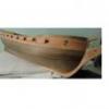
AnobiumPunctatum reacted to Cathead in Bounty launch by Cathead - FINISHED - Model Shipways - 1:16 - small
Okay, I just had to take photos in better light. Here she's set on the kitchen floor just inside our glass doors, with snow-softened light streaming in.
I like the lighter walnut stain on the gunwales, backrest, & knees setting off the darker cherry stain on the rest of the hull.
I have successfully resisted the urge to try treenailing anything, as tempting as it is seeing the gorgeous results of others. My goal going in was to built the kit "out of box" with nothing added, and I have largely stuck to that. Perhaps the next project I will go down that particular rabbit hole.
-
AnobiumPunctatum reacted to Remcohe in HMS Kingfisher 1770 by Remcohe - 1/48 - English 14-Gun Sloop - POF
Thanks all for your kind comments.
Nick, with diluted tung oil (applied sparingly ) it has no sheen and thats what I meant with dead flat. I have the mixture in a small jar and it will keep for at least 2 years, that is how long I kept is. Glue won't stick to well if the wood has been treated with tungoil or any other oil or wax based finish. So you'd better think ahead before applying it.
The fore mast step, this is a nice little 3D jig saw puzzle. I realised I had to reposition the two deck beams that incorporate the mast step to properly align with the mast. No big deal but I felt pretty dumb when I noticed my mistake. Most straight forward cuts were made on the table saw that acted as router. The rest was cut with a chisel.
Remco
-
 AnobiumPunctatum got a reaction from mattsayers148 in Bounty launch by Cathead - FINISHED - Model Shipways - 1:16 - small
Really nice progress. I like the color of your stain
-
AnobiumPunctatum reacted to Trussben in HMS Pegasus 1776 by Trussben - 1:48 - Swan-class sloop based on TFFM
Well on the 13th month anniversary of the start of the build the final full frame has been installed.
Ben
-
AnobiumPunctatum reacted to Jaekon Lee in HMS Alert 1777 by Jaekon Lee - 1/64
Garboard
Thank you Nils. Small update after long break.
For the start of clinker type planking of port side, the garbord strakes were attached along the keel. Rabbet was scored at the upper side of strake to receive the plank strake above.
Cheers, Lee
-
AnobiumPunctatum reacted to Dan Vadas in HMS Vulture 1776 by Dan Vadas - FINISHED - 1:48 scale - 16-gun Swan-class sloop from TFFM plans
Topmast Ratlines
Nothing real different here, just more ratlines. At this stage I only have most of the ratlines on the main topmast left to do.
Here are the foremast ones :
And the mizzen topmast :
Danny
-
AnobiumPunctatum reacted to Cathead in Bounty launch by Cathead - FINISHED - Model Shipways - 1:16 - small
Progress!
Facing the dreaded spreading-hull syndrome, I decided to tackle the issue head-on. With carpentry clamps. Using the thwarts as a guide, I set up two clamps and gradually tightened them until the thwarts fit snugly. Some minor hull popping and creaking made me nervous, but she's a strong little boat. With the clamps stable, I glued in all but the aft two thwarts (to leave room for building the quarterdeck).
Part of this process, though not shown, was aligning two thwarts properly with the mast steps. I inserted the dowels, held them straight with a square set onto the floor, and adjusted the thwarts as needed. The slow set time of carpenter's glue allowed this to work properly.
My gamble was correct; when the clamps were removed, the thwarts held the hull in shape. Test-fitting the gunwales proved that the original kit design is accurate; when the thwarts fit snugly, the gunwales will as well. So I glued them on, using the thick-rod-and-rubber-band method I stole from someone else (I have read so many Bounty Launch logs that I cannot keep them straight anymore).
On to the quarterdeck. I spent an afternoon reading about 8 build logs to develop my plan of attack for this, and decided to build the deck on the plans before installation. Here I stole an idea from my model railroading background, and laid a wide strip of masking tape face up, securing it with two other strips at each end. Then I laid the rough-cut cherry frames across the tape, which holds them in place for further assembly. The tape is translucent enough to allow for tracing appropriates lines to ensure accuracy.
At right you see the assembled deck, with hatch cut out. I left the frames long intentionally, and slowly cut them down as needed, with a lot of test-fitting, until the deck seated properly into the hull. I used a neat little tool for notching the hatch-planks (the plan shows it done this way, though some logs have used three full planks), also from my model-railroading background:
There it is on the left; the Nibbler. It takes perfectly square chunks out of strip wood, and is invaluable for cutting precise window/door holes in buildings and other projects. This is how I did all the windows on my steamboat. On the right is another excellent tool, the Chopper. It makes perfect 90 degree cuts of stock, with frames that let you set repeatable lengths. I use this for all manner of projects, and it is perfect for decking like this.
And here is the current status. The hull is effectively done, save one last sanding and perhaps one more coat of stain. Two insets show changes I made. On top, I made new quarterknees because the kit's did not fit properly with the angles my hull ended up with. They were too short, and the aft angle was wrong. So I traced and carved new ones. The stained piece is from the kit, the unstained my own replacement, cut from the same stock as the original.
The other inset shows my hatch-rope, an idea shamelessly stolen from CaptainSteve. His used a tighter loop; Bligh would probably trip over mine. But I went with a design that I thought would be more visible, if not quite as realistic.
Apologies for the color balance on these. Outdoors we are getting a mix of rain, snow, and other in-between mess that makes the indoor light rather dim and harsh. One of these days I will take this outside for some better photos.
I had intended to build this without masts, thinking it would fit better on a shelf somewhere. Fortunately, I happened to mention this to Mrs Cathead just before gluing in the thwarts, and she made it known that masts would be a good thing. So I took the extra time to align the thwarts and mast steps, which I would otherwise have not bothered to do. So very soon I will begin shaping masts and oars, and starting to feel sad that this wonderful project is now closer to its end than its beginning.
-
AnobiumPunctatum reacted to EdT in Young America 1853 by EdT - FINISHED - extreme clipper
Young America - extreme clipper 1853
Part 107 – Lower Hull Work
I finally finished the hull planking this week and got some other tasks well along. The first picture shows the full extent of the planking on the port side – as yet unpainted..
The deck is still masked for painting the white inside bulwarks. That work is now also finished and the installation of the painted waterways can proceed.
The next picture shows some of the seemingly endless task of treenailing the planking.
This work, too, is now complete on both sides of the hull. The picture also shows work on the rudder gudgeons. These were made by first silver soldering a tube into a groove in a sheet of .032” brass. The rough gudgeons were then ripped off on the circular saw as shown below.
The .032” brass – about 2 ½” at 1:72 – is too thick for the straps, but allowed the thick area at the hinge to be shaped. The 6” wide straps were then bent and filed back to about 1” thick. The next picture shows the bottom four installed using small brass nails.
The 16” aft face or the stern post is notched to receive the 6” wide gudgeons. These were aligned when being fitted by a stiff, straight rod through the holes. The end of the rod will mark the final center of the round helm opening – which must be on the hinge centerline.
The next picture shows the gudgeons on the starboard side.
The top one will be installed after this side is painted. Some of the lowest rows of “yellow metal” sheathing have been installed around the gudgeon. This will be the only gudgeon requiring this, since this is the lowest of the planking at the stern. The top of sheathing line – parallel and slightly above the load waterline - can be seen in this picture. There will be several rows of sheathing. The top row will be on the straight, horizontal sheathing line. The strakes below will follow the planking shear and “gore” into this top strake.
The brass plates were cut from .002” brass. The nailing pattern was embossed into the plates used an embossing device. The picture below shows the nail pattern being drilled in a wood block to make this.
The thickness of the block was sized carefully to allow small steel nails to be inserted from the underside. The tips protrude just enough to impart the pattern when stamped as shown below.
Stamping these plates is almost as thrilling as treenailing. Fortunately there are only about a half-dozen rows. A close up of the first few stamped plates is shown in the last photo.
After the pine stamping block “breaks in” the dimples become more regular. These are like little cheese graters. They are fastened with contact cement – another enjoyable task. After making and installing 3700 of these my Victory model, I swore I wouldn’t do this again – but that was in 1978.
Ed
-
 AnobiumPunctatum got a reaction from Jeronimo in La Salamandre by tadheus - 1:24
It's a shame, that you planked the hull on both sides. So nobody will see your really nice frameing job.
Wonderful build
-
AnobiumPunctatum got a reaction from mattsayers148 in Bounty launch by Cathead - FINISHED - Model Shipways - 1:16 - small
The color of the stain you used, is looking really nice.
Sorry to read about your problems with the hull shape. I hope you can solve the problem
-
AnobiumPunctatum reacted to tlevine in HMS Atalanta 1775 by tlevine - FINISHED - 1:48 scale - from TFFM plans
The bearding line was drawn on the fore edge of the rudder and cut in with a chisel. The advantage of the 4-part rudder blade is apparent here. The junction between the port and starboard halves of the rudder make an easily followed line. The width of the bearding is narrower at the bottom and gradually increases towards the top of the rudder. The bearding stops below the mortise for the tiller.
The rudder was positioned and the locations for the gudgeons were marked out. The recesses for the pintles were drawn and then cut out, leaving a little extra wood for final positioning later.
The width of the rudder is the same thickness as the stern post and tapers top to bottom. I took measurements off the sternpost and drew them into the pintle recesses for easy reference. The taper was sanded. I had taken the sole plate off earlier but have temporarily replaced it so one can see the amount of wood removed.
Next comes cutting the mortise for the tiller and then the dreaded metalwork.
-
AnobiumPunctatum reacted to Cathead in Bounty launch by Cathead - FINISHED - Model Shipways - 1:16 - small
Well, the advice squad has saved the day. I did spend Friday outdoors with a chainsaw and tractor mower, but never did I intend to resign the launch to such implements.
Using full-strength wood glue, smeared on hull joints and sanded down, worked charmingly. Embarrassingly well, given my reluctance to follow such advice earlier. Mea culpa, as Bligh would (not) say. Above you see three views of the hull after three more rounds of sanding, staining, and gap filling. It is better. It is still too damaged and streaky for my liking, but the gaps are solid and the color is better. Acceptable, and I have moved on, already looking forward to doing it properly on my next build.
I also want to point out the swiveling work stand which I purchased from Model Expo, and absolutely adore for this work. With the bolts tightened down, it holds any position desired and makes fiddly work much more pleasant. I have used it on previous builds but want to give it full credit here as a marvelous piece of equipment. Note the piece of felt stuffed in the vice grip to protect the hull/keel surface.
I did find one annoyance. For forming and gluing in the thwart risers, I used the same style of metal clamp shown in the instruction, as they are the only ones that can reach that far in AND are strong enough (clothespins, even reversed ones, did not hold). However, these clamps left noticeable dents in my otherwise finished hull. I have not yet attempted to sand them out, but it may be necessary. This was bothersome to say the least. I could not have inserted a protective spacer as the jaws do not spread that far.
On to the next stage. Thwart risers and such are attached, and I have begun on the main floor. Careful notching was required to get plank 2 around the main-mast step. I also felt the need to install two small pieces of scrap cherry framing at the bow end of plank 2 (both sides) to support the tip, as it was otherwise hanging in mid-air. The bright piece of wood you see at left is just a temporary spacer holding the unglued plank 2 away from the rest, so the notch and support can be seen (the hull is tiled at 90 degrees in this photo for best light).
The finished floor. I felt that a few of these pieces did not match up well, and attempted to shape them with mixed success. Some really wanted to flex out of position. I used CA to install these quickly, as no clamp can reach in here and I would be at this all week with wood glue. The instructions call for thin wood spacers, but I was afraid these would glue themselves in, so used pins gently inserted into the hull instead. Worked wonderfully.
On to the next dilemma. Upon test-fitting the thwarts, I discovered that the hull seems to have formed wider than desired, I assume due to pressure from the ribs spreading outward. In the photo above, every thwart is inserted fully to starboard, and you can see that toward the middle the hull is progressively too wide for them.
I assume that I will need to warp the hull back into shape for the gunwales anyway, and am considering gluing in all the thwarts on one side first, then somehow squeezing the hull into shape before gluing the other side to hold it all in shape.
The consideration here is that doing so means installing the quarterdeck beneath the glued-in thwarts. I am afraid that installing that floor first, as called for in the instructions, will make the hull too rigid to flex back into shape.
I remember reading someone's launch log talking about forming the hull back into shape, but cannot find it.
As you can see, I am not trying for the ultra-realistic weathered look, more of the slightly model-like "pretty" look. So far it is fitting reasonably with my goals for the project.
-
-
 AnobiumPunctatum got a reaction from rdsaplala in HMS Triton (1/64) by Aldo - POB
Yepp, that's what I mean.
-
AnobiumPunctatum reacted to tadheus in La Salamandre by tadheus - 1:24
Christian,
I cover the entire model strips. I do not like "unfinished" models.
Regards, Paul