


AnobiumPunctatum
-
Posts
1,283 -
Joined
-
Last visited
Reputation Activity
-
 AnobiumPunctatum reacted to pete48 in VOLVO 65 by pete48 - FINISHED - Scale 1/4" = 1' - Farr Yacht Design
I had not worked on this one for a while, so I thought I would set up to do the Hull graphics, and realized that I had some small gaps primarily where the Hull and Deck come together and mostly where the planks converge at the Transom. So I made up some filler, using sawdust and titebond 3, I then applied it on the gaps, Sandedup to 600 grit (once dried) and applied another coat of Flat white , Now I can set up for the Hull graphics . Here are the results
-
AnobiumPunctatum reacted to Dan Vadas in Cutter for HMS Vulture by Dan Vadas - FINISHED
Planking
As suggested in the instructions I've planked the hull of the cutter without the ribs - they'll go in later as most of them would come off the planking when the hull is removed from the plug. This pic was taken with a couple of runs left to do. I'm using Tamiya masking tape to hold the planks in position while they dry :
The cutter removed from the plug. It came out very easily :
Some pics of the outside. The planks need a "rolling" bevel both fore and aft to fit to the stem and transom :
There was very little excess glue inside the hull. These pics were taken before I started any cleanup :
You can see a couple of wedges in the bow which I inserted to ensure a tight fit to the plug. Isopropyl alcohol made removal of them easy :
Danny
-
AnobiumPunctatum reacted to Stuntflyer in HM Cutter Cheerful 1806 by Stuntflyer (Mike) - FINISHED - 1:48 scale
Planking above the wales has proven to be a rather time consuming process as a lot of time was spent getting a good fit between the gun ports. At one point I realized that I had the wrong curve, aft of the last gun port, which required a more upward sweep. Rather than replacing the whole plank I just added a filler piece after the curve was corrected. The filler piece is small and will eventually be covered by the fashion piece.
Photo showing one side completed above the wales and the small filler piece at the stern.
-

-
AnobiumPunctatum reacted to Chuck in HM Cutter Cheerful 1806 by Chuck - FINISHED - 1:48 scale - kit prototype
They are thinned down....thats their finished thickness. Check the plans.
See this example of a cutter stern from inboard...see how the frames are exposed? The top is the Cheerful from rogers collection and the bottom is Surly from the museum in Ontario.
Chuck
-
AnobiumPunctatum reacted to tadheus in La Salamandre by tadheus - 1:24
Christian thank you.
The beginning of the relation is available at this address:
http://5500.forumact...ndre-1-24#66516
Regards, Paul
-
 AnobiumPunctatum got a reaction from avsjerome2003 in La Salamandre by tadheus - 1:24
Really nice progress
-
 AnobiumPunctatum got a reaction from tadheus in La Salamandre by tadheus - 1:24
Really nice progress
-
AnobiumPunctatum reacted to kruginmi in HMS Druid by kruginmi - 1:48 - cross-section - Hahn
Hey, look at me, I can glue a deck clamp!
A long story (with a pretty happy ending so far...): I turned 50 in April and always knew this was going to be a breakout year. Not to linger on the point but after a series of events I was diagnosed with a rare disease (Mommy always said I was special). A few specialists and then a 3 week hospital stay I was back dealing with all the yard and house work that backed up.
But tonight, tonight I returned to the yard and cut and glued a deck clamp.
Well, that went so well I completed the keelson:
Not too much, I know, but a sign of things returning to normal. Now I have to look at a sprint Triathlon in less than 60 days and a lot of training I am behind on so who knows when the next update will be posted, but make no doubt there will be more.
Stay Building my Friends,
Mark
-
AnobiumPunctatum reacted to tadheus in La Salamandre by tadheus - 1:24
Continuation.
The beginning of the relation is available at this address:
http://5500.forumact...ndre-1-24#66516
Regards, Paul
-
AnobiumPunctatum reacted to tadheus in La Salamandre by tadheus - 1:24
Continuation.
The beginning of the relation is available at this address:
http://5500.forumact...ndre-1-24#66516
Regards, Paul
-
AnobiumPunctatum reacted to tadheus in La Salamandre by tadheus - 1:24
Continuation.
The beginning of the relation is available at this address:
http://5500.forumact...ndre-1-24#66516
Regards, Paul
-
AnobiumPunctatum reacted to Gaetan Bordeleau in Le Fleuron by Gaetan Bordeleau - FINISHED - 1:24
I had anchor cables done from previous works and they match. Cable circumference is breadth/24 : 41.84/ 24, C : 2pi r, Diameter:6.64 inches and at scale 1/24 :.28 inch. I am sure that if they had micrometer during that period they would have measured not the circumference with a rope but the diameter.
During myfirst professional job, I bought a camera. Up to now Olympus was always my first choice and I was happy with it. Now I will experiment with a full frame Canon camera. They are very strong with the light sensibility and they have a wider variety of programs for the photos manipulation.
-
AnobiumPunctatum reacted to mtaylor in Licorne 1755 by mtaylor - 3/16" scale - French Frigate - from Hahn plans - Version 2.0 - TERMINATED
I think you're right, John. Better now?
-
AnobiumPunctatum reacted to mtaylor in Licorne 1755 by mtaylor - 3/16" scale - French Frigate - from Hahn plans - Version 2.0 - TERMINATED
After reading all the theories and "how-to's" where the rubber meets the road.... I'd like some feedback on my batten. I'm planking from the wales down to the batten first. The batten represents where the wide wale planks will end... or should end.
-
-
AnobiumPunctatum reacted to EdT in Young America 1853 by EdT - FINISHED - extreme clipper
As always, I appreciate all of the comments so many have made on the Young America project. I am sorry that it has been well over a month since the last progress report. The model work has been on hold for a few reasons - work on the book manuscript, a two week vacation from which we just returned, and the need to do research and drawings for the next phases of the build - fitting out the main deck, masting and rigging. I do not expect that there will be much progress on the model until later in the summer.
However, during that period I will be posting progress on the 1:96 POB version of the model that has been constructed for demonstration purposes - to support the POB modeling processes that are also described in the book. Some may find this model and its contrasts with the 1:72 framed model interesting. I will start a separate build log for this. Since that model has progressed to the point shown in one of the above posts, the build log will be somewhat retrospective, but I will continue it as far as I decide to take that model. My intent with the smaller, simpler model has always been to take it to a point where remaining work on both versions can proceed from the same process descriptions. That has been done and the final chapters in Volume I of the book apply to both versions. However, I am considering continuing the POB build to a more finished state.
Again, thanks to everyone for the continued support and comments.
Ed
-
 AnobiumPunctatum got a reaction from UpstateNY in H.M.S. Triton Cross Section by UpState NY 1:48
Welcome to the Triton shipyard.
-
 AnobiumPunctatum got a reaction from mtaylor in Naval Cutter Alert by AnobiumPuncatum - Scale 1/36 - POF
Mike,
thanks for your interest, but I don't have an update for my log in the moment.
I didn't found the right arrangement for the cant frames until now. I found another sheer and profile plan in an Danish archive, which I have to study. If I found a possible solution for the cants I'll update the log.
in the moment I work on my second project HMS Fly 1/32.
-
AnobiumPunctatum got a reaction from mtaylor in Naval Cutter Alert by AnobiumPuncatum - Scale 1/36 - POF
Thanks for your opinion. I will check this detail also with the other Sheer and Profile plan.
-
AnobiumPunctatum reacted to druxey in Naval Cutter Alert by AnobiumPuncatum - Scale 1/36 - POF
Somehow, I missed your January 3 posting and am a bit bothered about that fifth deadeye and chain. Usually if modifications are made, these are drawn out in detail neatly, using either a different color ink or with dashed lines. This rough pencil addition looks like a proposal that was not, in fact, carried out. Just my opinion.
-
 AnobiumPunctatum got a reaction from druxey in Naval Cutter Alert by AnobiumPuncatum - Scale 1/36 - POF
Mike,
thanks for your interest, but I don't have an update for my log in the moment.
I didn't found the right arrangement for the cant frames until now. I found another sheer and profile plan in an Danish archive, which I have to study. If I found a possible solution for the cants I'll update the log.
in the moment I work on my second project HMS Fly 1/32.
-
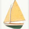
AnobiumPunctatum reacted to pete48 in Herreshoff Alerion by pete48 - FINISHED - 1/2" = 1' Scale - SMALL
Today, I started by finishing up planking the Hull, Next I faired the Hull sanded up to 400 grit ( starting with 220 grit ) I then made the cradle. Next will be to seal up the outside of the Hull and start detailing the Cockpit. Here are the results
-
 AnobiumPunctatum got a reaction from pete48 in VOLVO 65 by pete48 - FINISHED - Scale 1/4" = 1' - Farr Yacht Design
Really nice model. I took the time to have a look in your other logs. Really intersting,I didn't know Herreshoff before.
-
AnobiumPunctatum reacted to Siggi52 in HMS Dragon 1760 by Siggi52 - FINISHED - Scale 1:48 - English 74-Gun ship
Hello,
now it is done, the upper gun deck is ready! That was a lot of work and research and not always easy.
I will not write much, because of my english, but I think the pictures say all.
Regards,
Siggi