


AnobiumPunctatum
-
Posts
1,233 -
Joined
-
Last visited
Reputation Activity
-
 AnobiumPunctatum reacted to Chuck in HMS Winchelsea - FINISHED - 1764 - by Chuck (1/4" scale)
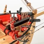
OK finally the guns are all done.....I just have to make one more eyebolt per gun carriage....for the inhaul. I always forget those until I take pictures.
The corresponding eyebolts and split rings were added to the bulwarks. They were made the same as those for the gun carriages. I used 24 gauge black wire. The split rings were the same also using a 41 drill bit to make them.
There are also eyebolts/split rings on deck for the carriages which were also made the same. BUT, if you examine the plans there are also 8 larger rings which need to be added. I added those at this time also. Those were made from 22 gauge wire using a #31 drill bit. You can see I forgot the one eyebolt on the back of each carriage....so I will add those at some point. Man that was a lot of eyebolts and split rings to make....sheesh!!
Remember that I wont be rigging them so they will look just as you see them here. But the beauty of not rigging them means that I dont have to glue them into position permanently yet. I will wait in case removing them makes it easier to work on the other fittings in the next chapter. But if you are going to rig them....this would be the time. I will rig one just to explain how I do it but then I will take it all apart...
Also remember that you wont be able to rig 4 of the guns yet because the eyebolts are actually located in the hanging knees. Those will be added early in the next chapter. So no worries there. Check the plans for those....
And the proverbial pic leaving the camera on deck facing aft showing all the guns....Next up I will rig that one cannon for you folks and start on chapter seven.
-
AnobiumPunctatum reacted to dvm27 in Speedwell 1752 by dvm27 (Greg Herbert) - FINISHED - Ketch Rigged Sloop
It's been almost a year since my last update. The reason is that Speedwell has been landlocked in Canada since last November. My very talented collaborator David Antscherl had made and applied all the carvings and I was going to pick her up to rig her just when Covid struck and the border was closed. I have all the blocks, ropes, masts and spars ready but no model. I'm hoping to get her this summer but who knows at this point. At any rate here are some photos of her sporting her wonderful carvings.
-
 AnobiumPunctatum got a reaction from FrankWouts in HMS Winchelsea 1764 by tenderfoot
What you see, comes mostly from the laser. It doesn't cut perpendicular to the wood. After a little bit of sanding the outside is looking fine.
This is the stem of my model build with the parts, Chuck provides.
-
AnobiumPunctatum reacted to bartley in HM Cutter Cheerful 1806 by bartley - FINISHED - 1/48 scale
Post 55: the Main Gaff
This was made in exactly the same manner as the main Boom above. The only thing I would add is that in order to ensure that both jaws were identical I used the "spot of glue" technique which I thank Dan Vagas.
Here are the two spars completed
John
-
AnobiumPunctatum reacted to bartley in HM Cutter Cheerful 1806 by bartley - FINISHED - 1/48 scale
Post 54: the Main Boom
This was trickier than it looks as the outboard end tapers to a diameter of only 2.5 mm.
I first make the boom octagonal using the 7:10 :7 rule and then plane of the corners with my Veritas block plane.
Then I turned the inboard end first down to a diameter of 5.3 mm. On my home made lathe the central board is usually a moveable support but this time I clamped it in place at the widest point and then tapered to the outboard end. I use decreasing grades of sand paper from 130 down to 400 but like any rotational method it does leave slight radial grooves so I finish of with 400 and 600 grade paper in the longitudinal direction
The bearings on this device are roller blade bearings and I have a number with wooden inserts to reduce the diameter:
These ensure that the mast (or boom) in this case fits firmly so that there is no scoring since it is the bearing which rotates. Here is the completed boom after turning to the shape indicated in the plans:
The next task is flatten the inboard end to take the crutches which connect the boom to the mast. I used the mill for this with the head set to an angle of 2 degrees :
Next the boom crutches themselves. I used my Knew Concepts Jeweler's saw for this, and then finally shaped with files and sand paper.
On the subject of Jeweler’s saws: I originally owned one like this
I had a problem finding the correct tension and kept breaking blades. This was probably down to my poor technique and perhaps I should have persisted. However, recently I have acquired a Knew Concepts saw and for me this is a much superior tool. The lever system ensures the blade is always at the correct tension. It is beautifully balanced so I can cut really close to the line and I have not broken a blade in nearly 12 months.
I would recommend these to anybody about to purchase a jewelers saw. They are not cheap but like most things quality cost money.
Some would use a scroll saw for this task. I did own one of these but it was a cheap model – I paid A$80. I was disappointed. Even though I bolted it to the bench over a rubber pad it still exhibited lots of vibration. The foot designed to hold the work down constantly came loose and for thin timber, say 1/16 inch, I could not install fine enough blades to meet the “three teeth rule” so there was lots of tearing. So, in the end I sold it and made more space in my workshop.. I have written about this elsewhere on this site. My local woodwork shop does weekend workshops and demonstration and I have trialed out there a parallel arm scroll saw. These are a very different story. Virtually vibration free and they will take finer blades so quite fine work is possible . A fine tool. They do however cost about A$1000 and are out of the question for me. A nice tool though.
I digress! So, here is the boom with crutches installed
And finally with the blocks added and ready for installation
John
-
AnobiumPunctatum reacted to Alex M in HMS Sphynx 1775 by Alex M - Scale 1/48 - English 20-Gun Frigate
Hi all, a little update from me, slowly process...
Alex
-
AnobiumPunctatum got a reaction from FrankWouts in HMS Winchelsea by scrubbyj427 - 1:48
Your stern is looking really beautyful.
-
AnobiumPunctatum reacted to wyz in HMS Winchelsea 1764 by Wyz - 1:48 scale
Over the past three days I started to shape Winnie ll with mallet, chisels, gouges, a block plane and a few power tools. Exterior shaping is pretty much where I was at on Winnie l when I hurt my back, but the interior hollowing out is, as you can see, much further along. Although the model is 6.2 lbs lighter than when I first began it's still quite heavy at 18.6 lbs. The Jet Air Filtration System was suspended from the ceiling today, so I was free to use the heavy dust producing power tools. Very soon I will start hull shaping with the set of plywood templates I made. The photo of the work bench shows the tools I used on the first pass.
-
 AnobiumPunctatum got a reaction from glbarlow in HM Cutter Cheerful 1806 by glbarlow - FINISHED - 1:48
Glenn,
thanks for the really nice descriptions. This is very helpful for me.
-
AnobiumPunctatum reacted to Blue Ensign in Queen Anne Royal Barge circa 1700 by Blue Ensign - FINISHED - Syren Ship Models - 1:24 scale
Post Eleven
Flying Transom.
This is another tricky piece to hold in the correct position whilst the glue bites.
1192
I used pva and bamboo poles to secure the angle and to support the Flying Transom whilst the glue bites.
It allows me time to sight and check the Flying Transom set-up from various angles.
1201
1208(3)
1214
With the Flying transom in place I use a template taken from the plan to mark the curve down from the underside to the Transom base.
1224
The stern area is then taped up to provide stability for the next stage.
1226
I then carefully pare down to this line using a No 11 scalpel.
1228
The plank ends are then sanded back to the Transom face.
1234
1232
1231(2)
The next stage sees her released from the base and the removal of the frame centres.
B.E.
21/03/21
-
AnobiumPunctatum reacted to glbarlow in HM Cutter Cheerful 1806 by glbarlow - FINISHED - 1:48
That’s one, only 11 more, or 44 more blocks, 44 more hooks, 24 rope coils, and 66 seizings. The breech ropes are done though.
Fun stuff😁
-
AnobiumPunctatum reacted to glbarlow in HM Cutter Cheerful 1806 by glbarlow - FINISHED - 1:48
Bowsprit and Mast
With all the hull and deck furnishings made its time to mount them to the deck…except it isn’t. I decided I needed to make the bowsprit to ensure I put the bowsprit step in the right place and I shaped the main mast to ensure the mast coat and mast slot were correct and because I was on a roll turning square things round.
Thanks to my having to restart after my dropped hull (still makes me shudder almost a year later) I have two sets of plans. This has come in handy, allowing me to do cut outs of various sections while keeping one set whole. In this case I cut the bowsprit and mast so I have them right by the work piece. I marked the square piece of cedar using the 7-10-7 rule and used the mill as a drill press to drill the three holes at the base - I later used a file to square the two forward holes that would be visible once mounted. I also drilled the hole for the sheave at the forward end, much easier to to that while its squared - and as advised by Chuck’s monograph.
Then to the jig I sorted of copied from Derek to convert the square into an octagon for both the mast (shown here) and the bowsprit using my quite handy finger plane, that once again proved perfect for the job. I’ve mentioned before I’ve never had any luck with planes, but this little jewel works perfectly in making long smooth strokes on the square edge. The key, for me anyway, is to expose very little of the cutting blade on the bottom so it only takes a little wood off per stroke. I’d rather do more strokes than go too deeply into the wood.
Then it’s off to the lathe for its first real use. I left enough stock on the end for the chuck to grab onto. I had been concerned (not sure why it was never an issue when I did it with a drill before getting the lathe) that there would be too much wobble not having both ends steady. It proved not to be a problem by using my right hand to steady the end while the left hand did the rounding. I used only various grits of sandpaper, 150, 220, 320 and 400 as I progressed, no tools needed. I took the measurements at incremental points along the stock (here the bowsprit, same thing for the mast) and stopped to check them frequently with digital calipers. I can’t put it back on, better to take it slow and enjoy the massive amount of sawdust it creates.
At least for this task there isn’t a huge difference in the lathe and the hand drill in doing the rounding. The big difference is the quick on/off to do checks and the placement and hold of the stock makes things easier than holding a drill. Some of the jigs I’ve seen for holding a drill are likely just as good, but the Proxxon DB250 is inexpensive and worth the price as I’m sure there is more I’ll do with it later. Another plus pointed out by Derek is the ability to push the wood thru the chuck which though not needed for masts and bowsprits will come in handy later for spars.
The mast is squared down at the top and includes an off center sheave - I did both before rounding the rest of the mast.
A quick check for fit. I sat the hull on its final stand temporarily to ensure when mounted there is a slight rise. It’s interesting how long the bowsprit is on a cutter relative to a square rigged ship.
A check of the mast to make sure with the coat I can get it both level and slightly slanted towards the stern. It’s a little off in the photo, it won’t be when I mount it later. This step turned out to be worth the time, I did have to make minor adjustments. These were easy to do now, not so easy if I’d waited after all the deck furniture, the winch in particular, had been mounted. I got to make a new mast coat, the first was too small, but that’s ok, making them is kind of fun. This one from boxwood got a few coats of WOP after I was sure of the fit.
Another trip to the mill to flatten the area for the mast cheeks, just a .25mm deep cut for now, I will shape in more once I have the cheeks in hand.
Following a couple of coats of WOP the bowsprit and mast are done for now. There is much more to do on the mast later (the photos are a bit out of sequence, I’d cut off the extra on the bottom of the mast before test fitting).
The bowsprit has an iron ring (black shrinkable wire wrap did the job) and four blocks. I added the ring and drilled the holes but will add the eyebolts and rings after the bowsprit is mounted. For me it’s easier to rig the blocks off the ship then glue them in (a practice I’ll follow throughout the rigging). The standard commercial eyebolts work in some circumstances on Cheerful, but not all - the bowsprit is one such place. The commercial versions were much too ’skinny’ to look right so I made four from 24 gauge black annealed wire.
I suppose everyone comes up with their own way of making these. I tried finding some options on MSW but didn’t really find anything I liked so I came up with my own using various pliers, shapers, cutters, and vise. I experimented and decided 1mm was the right size so I reversed a 1mm bit in a pin vise. A tight turn, a couple of bends and two cuts and I had it. It being (once again) my first time making these it took a little practice and rejects. But once I got on a roll, I made a bunch for all the eyebolts on the outer hull and cap rail as determined from the plans.
With eyebolts in hand I turned to the quad hands to rig the four blocks. I’m using fly fishing line to seize these and other blocks but will also use regular thread when I want the seizing to be more visible. Here I have the eyebolt (hidden from view on the right) in one loop and the block in the other. I use my standard loop and wrap method for all my seizings, it works for me. I’ve always had a third hand tool for this work, but the newly acquired quad hands is a big step up from those and well worth the expense. The flexible clip arms and having four to hold different things really makes the job easier. A completed block is shown on the far right, but the clip hides much of it.
Thanks mostly to Cheerful, the power tool corner of my workshop has become a bit crowded. It’s usually not this much of a mess, I was working on the mill and the lathe at the same time. My shop dust filter was working overtime to clear the room as was my dust mask. The dust buster and broom came out after this photo. The tool chest holds all the accessories required for the power tools and was a Christmas gift from my supportive wife.
Much of this post probably seems mundane, but it accounts for a lot of time. These small ultimately taken for granted steps are integral to the completed model. For now the bowsprit, mast, and rigged blocks go onto the shelf (I have a literal shelf in one of my cabinets with a soft cloth lining) until its time to mount them. The next step, and the last prelude to mounting everything, is rigging the cannons. That will be my next post. It’s a long process to do one, then 11 more after that one.
Thanks for stopping by, the comments and likes are very appreciated.
-
AnobiumPunctatum reacted to glbarlow in HM Cutter Cheerful 1806 by glbarlow - FINISHED - 1:48
The last two items for me to make in completing the hull are the elm tree pumps and the fixed block, the first from Chuck’s mini-kit the second a scratch build.
Elm Tree Pumps
The first step is applying the 7-10-7 rule to a square piece of boxwood then using that to create the octagon shape of the pumps. The jig I used won’t win any ‘pretty’ awards, I modified it to work from a different jig, but is was effective in holding the small wood piece steady while I shaped it using my favorite finger planer. Between the planer, a file, and a sanding block I was fairly quickly able to get both pumps converted to octagons.
I painted the handle and bracket before removing these laser cut pieces from their frame knowing I’d have to paint them again, it made doing that easier. The bracket has to be slice cut at its top to accept the handle, so back to my favorite mill again. This could be done by hand with a file I’m sure, but again, there’s a mill just sitting there. Though a simple cut it is very delicate and requires careful measuring - as you can see there is not much room to be wrong. The resulting hinge opening is very delicate, I was fortunate not to break one but if I had Chuck does include 3 of both the handle and the bracket in the mini-kit.
I drilled two holes at the proper deck location and inserted brass pins in the base of both pumps. It made it easier to add the spout and easier to paint holding them with my hemostats (more dental tools) as well as to install the metal (black paper) band around the top. Chuck provides enough strip if you want to add another band at the bottom. I like the way these look without that. Either way is historically accurate for those counting.
I rounded and softened the edges of the handle for a used look. Lining up the wire pin through the bracket and handle was fun... A quick dry fit and then off they go to my construction shelf to be mounted later. The handles move so I can position them. I’ll have to watch closely to make sure they aren’t snagged during the rigging. Though they do move I did not test to see if they remove water from the bilge.
Fixed Block
Next up is the fixed block on the starboard side of the stem. For this I had only the plans to go by and consulting of other logs for ideas, once again the strength of MSW. This turned out to be a pleasant afternoon’s project start to finish. It was fun to figure out and make.
I started with a piece of scrap boxwood - I just love boxwood, it’s so nice to work with, shape and polish into shape. I’m glad when I have a use for it not calling for paint, it is also very complimentary to the model’s yellow cedar. I cut a piece longer than I needed 6mm wide (per the plans) and 3mm thick (just looked right, no way to tell from the 2 dimensional plans). I suppose I could have made it from a piece 2mm thick but with its required U shape I was concerned it might break at the joints. Of course this is a task the mill is perfectly designed for, much crisper and faster than I could have done it by hand. Have I mentioned how much I enjoy having the mill…
I failed to take a photo of the reverse side of the block - essentially it’s cut to a block form U (as can be seen in the previous photo). The plans call for the ‘indention’ to be 6mm long and deep enough to hold the sheave, and as it happens a perfect fit for a 5mm pear wood deadeye I took from my Speedy kit. I drilled a hole in the center of both the block and deadeye, I did have to sand the sides of the deadeye considerably for it to fit between the block and the stem, which is ok, it looks like a sheave now. I drilled a hole for a 22 gauge wire center for the sheave and four 24 gauge wire mounting holes.
The extra length was handy for testing holes and for holding the piece both in the mill vise and on the work bench. Once everything was ready I carefully sliced it off with the cross cut sliding table on my Byrnes saw. You can also see the measurements (1mm turns of the axis wheels) and notations used for cutting it on the mill, I have to do this otherwise I lose track.
I spent a considerable amount of time with fine and extra fine sanding sticks to round it off and shaping it to look a little worn and pounded by the waves, then attached it with CA and firmed it up with the wire mounts. I had mounted the center wire and deadeye first. The uncut center wire was handy in giving me something to hold on to while lining it up on the stem. I roughed up the contact points where the block and stem meet for adhesion, there’s a lot of poly on the stem.
With the wires cut to stand proud and their tops painted Iron Work Black and a coat of WOP the block is done. So is all of the deck furniture, though most not yet mounted, making this something of a milestone. Next up is making the bowsprit. I need it to determine the location of other pieces. Once I have that done I’ll next rig the cannons while there’s room then mount the remaining deck furniture, bow sprit, and mast. I’ll pause to enjoy the work, then it’s time to rig.
One decision I haven’t made is whether to include anchor hawse running across the deck. I like the look but not sure I want to cut holes in the forward hatch, I’ll have to decide soon though.
Thanks for all the likes and comments, I appreciate and enjoy your taking the time.
-
AnobiumPunctatum reacted to Matt D in HM Cutter Cheerful 1806 by glbarlow - FINISHED - 1:48
It looks like you're in a lot of trouble, there. Next you'll have to walk the plank!
They look excellent, Glenn.
-
AnobiumPunctatum reacted to glbarlow in HM Cutter Cheerful 1806 by glbarlow - FINISHED - 1:48
My Arsenal is complete
Now which way do they point...
-
AnobiumPunctatum reacted to michael101 in HMS Victory by michael101 - Caldercraft - Scale 1:72
Here is a little update ,
very usefully jig for marking vertical lines on the ship i hope it will help other builders
so, here i have marked the bulkheads lines on the first plank and also the pattern of the butt shift system on the middle of the ship ..
but i will talk about this method later ..
here is some pictures :
Best regards,
Michael.
-
AnobiumPunctatum got a reaction from FrankWouts in HMS Winchelsea 1764 by oorsouw53
Hoi Jan,
hartelijk welkomen in onze groep en veel plezier bij het bouw van deze mooie model.
(welkom in our group and a lot fun building this fine model)
-
AnobiumPunctatum reacted to JpR62 in HM Cutter Cheerful 1806 by JpR62 - 1:48 scale
Thanks to all the 'Likes'.
This week, I put the planking between the wales and the first layer of the molding.
For this I used the method described by Chuck and proceeded to shape the planks using a small travel iron and a hair dryer.
I have to say that this method works pretty well and makes it easier to get the planks in place.
I found that the second strake, the one that fills the space, was still difficult because the width of the planks must be really precise.
The next strake should be easier as it will consist of a constant 5/32" width, although here it will be the length that needs to be precise to leave a 1/64" gap around each gun port.
-
AnobiumPunctatum reacted to Chuck in HMS Winchelsea - FINISHED - 1764 - by Chuck (1/4" scale)
Someone mentioned deck beams earlier. I managed to get all of them sanded of char. I will need them as I move forward and thought it best to do them now while building cannon. Some knees will need to be in position to finish the cannon so these are good to have....but it really does change the appearance and gives you a great idea of how she will look. I will number them and remove them until needed.
-
AnobiumPunctatum reacted to Chuck in HMS Winchelsea - FINISHED - 1764 - by Chuck (1/4" scale)
Guns!!! Guns!!! and more guns....
Eight down and 16 more to go. I have been very busy making these. Just take your time and go slow so they come out nice and neat. Some photos of my week of work making 8 cannon....
-
 AnobiumPunctatum got a reaction from GrandpaPhil in HM Cutter Cheerful 1806 by AnobiumPunctatum - scale 1/48
Today I found time to sand the first half of the hull. After removing the adhesive tape at the keel I have to sand a little bit at the stem.
Those who can read have a clear advantage. 😉 If you see, I didn't follow Chucks advise, I simply overread this. So I copied the marks on the other side of the frames.
-
AnobiumPunctatum got a reaction from GrandpaPhil in HM Cutter Cheerful 1806 by AnobiumPunctatum - scale 1/48
In order to be able to securely fasten the model to the stand, two recesses for nuts were milled into the keel board and two holes were drilled for M3 threaded rods.
Today I glued the ribs into the prepared keel board. For the right-angled alignment I built small auxiliary constructions out of Lego bricks.
-
AnobiumPunctatum got a reaction from GrandpaPhil in HM Cutter Cheerful 1806 by AnobiumPunctatum - scale 1/48
Next step was to form the rabbet. I used therefor a scrap piece from the false keel.
After drying, the spooning was glued to the false keel. During the drying process the paper clips proved their worth.
I sanded the taper the stem with sandpaper. Finally, the stem and keel were glued to the ensemble.
As you can see in the photos, the shape of the taper is not perfect, but the planking will cover that later.
-
AnobiumPunctatum got a reaction from GrandpaPhil in HM Cutter Cheerful 1806 by AnobiumPunctatum - scale 1/48
In 2016 I bought Chuck's Starting set from a fellow modeler who became a father. I glued the false keel together and then packed everything in a big box. While preparing the Winchelsea build, the box fell into my hands and I decided to build both models more or less in parallel. I can practise all the building steps on the much smaller Cheerful model before I do them on the Winchelsea.
Since the false keel I built at that time was no longer usable and I want to build the model from Yellow Cedar, I asked Chuck for spare parts. These arrived on Saturday morning with a small delivery of wood. Many thanks for the first class service, @Chuck .
I will build the model according to the instructions and with the help of the mini-kits. I have only one change planned - I want to copper the underwater hull.
The slipway is a bit big for the small cutter, but as I still had it, it was reactivated.
On Saturday evening I glued the false keel together and let it dry overnight. The frames could only be pushed into the recesses with difficulty - the thickness of plywood is always subject to slight fluctuations. I made a small sanding stick out of 180-grit sandpaper and a suitable strip. Then go over the lasered edges two or three times on each side and the frames fit perfectly (the frames are not glued in now).
Finally, the stem was assembled.
-
AnobiumPunctatum reacted to TonyM in Exploring FreeCAD for ship modeling
Starting this topic to explore the FreeCAD program and discuss techniques to be used. Being relatively new to the 3D CAD scene, the approaches will be relatively simple and sometimes wrong and can be improved.
The project used as an example is a hull model of the New England fishing schooner Adventure and supporting information from http://schooner-adventure.org/about-us/ and details from Howard Chapelle's "The American Fishing Schooner". At some point photographs of the real schooner will resolve details.
The objectives of the project are to understand some techniques for getting the 3D hull built, to get as realistic rendering as possible, and explore the opportunities for 3D printing with various options.
I have been inspired by some amazing work in other topics in this forum "CAD and 3D Modelling/Drafting Plans with Software".
Attached is a current rendering with many unresolved issues. I plan to go back and show how this was assembled and then move forward on the issues.
Hoping that this will be of interest and that others will contribute.