HOLIDAY DONATION DRIVE - SUPPORT MSW - DO YOUR PART TO KEEP THIS GREAT FORUM GOING! (83 donations so far out of 49,000 members - C'mon guys!)
×


DaveBaxt
-
Posts
1,324 -
Joined
-
Last visited
Content Type
Profiles
Forums
Gallery
Events
Everything posted by DaveBaxt
-
Now that I am aware of this ,I would like to incorporate this into my current build but fear I am now too late for the stem as it is already fitted to the model. The others it is perfect timing so thank you Allan for bringing this to our attention.
-
Decorative trim/rail
DaveBaxt replied to DaveBaxt's topic in Building, Framing, Planking and plating a ships hull and deck
I would like to thank everyone who has participated in this great thread and I apologise to any person who I have not acknowledged personally. Some great replies which has set me hopefully on the right path to producing something that looks reasonable to the eye. Best regards Dave -
Decorative trim/rail
DaveBaxt replied to DaveBaxt's topic in Building, Framing, Planking and plating a ships hull and deck
Yes Jason I have been following your log with interest and have now got my safety razor blades and a dremel diamond cutting wheel to make my own shapers. It was your good self who made me think of all this in the first place. . I therefore thank you again for your help in producing such beautiful work on you Diana and sharing you work experiences with us. Keep it up as it is always very helpful. I had a feeling that that might be the case regards walnut having too big a grain, but fortunately I have a good stock of boxwood which I bought for making masts Best regards Dave -
Decorative trim/rail
DaveBaxt replied to DaveBaxt's topic in Building, Framing, Planking and plating a ships hull and deck
That would be amazing but it would depend upon how much ot your time you would want to take up but making perhaps something that is needed in a popular scale would be ecellent news. Any making of such items as discussed here I would happily pay for but I would imagine you have many friends on this forum and others who would say the same but understand if you decided not to. Best regards and thank you again for your input. -
Decorative trim/rail
DaveBaxt replied to DaveBaxt's topic in Building, Framing, Planking and plating a ships hull and deck
Thank you Gregory for your input and your thinking is correct and that is exactly what I am trying to achieve and will be interesting to see how they are built up using a laser printer. I was hoping that someone somewhere might make them and then sell them. Hopefully someone will think it is worth their while to do this. Anyway thanks again and I will take a look.Best regards Dave -
Decorative trim/rail
DaveBaxt replied to DaveBaxt's topic in Building, Framing, Planking and plating a ships hull and deck
I definately will give those shapers ago.They look great on the video. I have noticed that they are possibly being used on lime or perhaps some other type of soft wood. I have quite a bit of lime and lots of walnut in small sizes. Do you think they would work on walnut too? Perhaps it is possible to use these for making the scrolls out of a square or round flat piece of wood. Any one tried this? -
Decorative trim/rail
DaveBaxt replied to DaveBaxt's topic in Building, Framing, Planking and plating a ships hull and deck
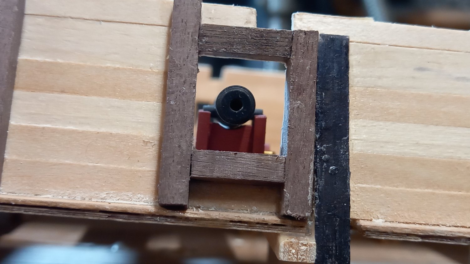
As ever a great reply Bob. I had a feeling wood is probably the way to go and you have added some excellent tips. The micro shapers look like an excellent tool for making your own trim. In fact the photo I added is from Beef Wellingtons Diana, where has made his own shaperes using made from safety razorblades. Something which I might try myself. However I am just looking at different ways to achieve a similar result. So I might look into the ones supplied by Artisina. It also looks like I might have to try my hand at carving the scrolls on the end. Perhaps someone might add any tips on how this is achieved as well. Thank you again Bob.Best regards Dave -
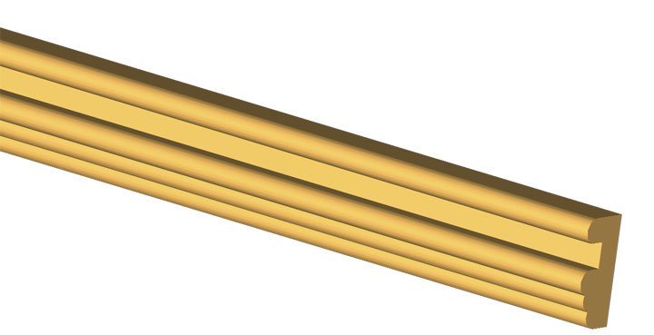
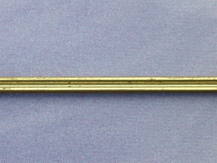
Sorry if this should be under metal work as the Trim I have bought from caldercraft and is made out of brass. Below is a photograph of one of 3 different section. I intend to use this mainly on the hull. There are certain areas of the ship I am building which require this to be shaped/bent into position. My question is this.Would it be possible to shape this into an end like a scroll or does this need to be carved out of wood .See photo below. I know some modellers make theirown rail and I have thought I would see how well the brass works. However I am not sure I could carve the end of the rail/trim
-
Thank for taking those photos and posting them on this thread.excellent workmanship on what is quite demanding with so many gun ports.The Victory is definitely the ultimate build..Thank you once again for your input on this subject matter. Best regards Dave.
-
Thanks for those great photos Jason. They really show us and other stuff in detail and these photos have cleared a few things up too. So well done . I will have to take another look at the Trincomalee which is about 30 mins in the car from me. I had my better half and Grand son with me last time and I need to take more photos of the ship than my Grandson next time Ha ha! After reading up Peter Goodwins book together with the afore mentioned photographes the normal skid beam clamps are not supplied by CC and I think are probably beyond my skill level in making them. However I think David's idea together with AOTS Diana of using the decretive strip under the length of the skid beams is an excellent solution to this. I also think that the fitting of what will look like deck clamps( My next ship will be fitted with thicker material in this area should be fitted.) This subject has been facinating to say the least and evey day there is more to learn. Again a big thank you to Allan & David for their time and patience. Best regards Dave
-
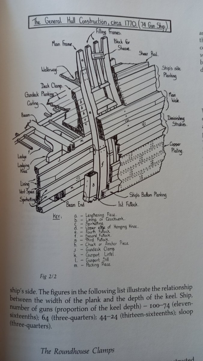
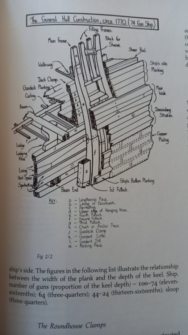
Allan and David. Your patience holds no bounds and forgive my ignorance and trying to clear this up for me. So there is no deck clamp fitted on your Diana only the skid beam clamp and spirketting fitted. Please forgive my mistake I also thought there was a deck clamp fitted on your other photo I posted. Thank you also Allan for posting some more great photos but I can only make out the spirketting and not the deck clamps so will need to do some more reading on this as I am not entirely sure what I am looking at other than Daves photos and the drawing I posted. The link to page 210 in Goodwins book also clearly shows the deck clamp and the scuppers, which is something else I wll possibly need to fit aswell . So it would be safe to add the deck clamp above the gun port with it being bearded at the bottom, although I do like the look of Daves skid beam clamp ( page 61 AOTS Diana item 5 DaveEN's reference) I appreciate all the help you are giving me guys.Thank you Best regards Dave
-
Allan. My source is Peter Goodwins book The construction and fitting of Sailing Man of War.Here is the drawing- Hope this works , as I am doing it from my phone. Here is a photo of the deck clamp on another Diana model. I am not familar with the name but assume this is what hs been added to another modellers ship. perhaps you have something else in mind her is the decorative strip I was talking about earlier. I hope David does not mind me using his HMS Diana for representation.


-
Thank you David for keeping my right. You have a really good eye at looking at the AOTS drawings, most of which are still a mystery to me. David , can you remember what material you used. I know you can get different profile walnut from Cornwall ship models or did you just use a couple of very small walnut square stock or similar. I know Jason ( Beeef Wellington) makes his own rail but as yet I haven't mastered that skill. By the way your gun ports look terrific.
-
My thoughts at present are mainly the oar holes or lack of them. I think doors for these are fitted to the outside but not sure if these are actually holes in the side. I am still thinking of fitting a spirketting and clamps top and bottom of the gun ports ( inside planking). I got this information fromPeter goodwins book the 'Sailing Man of War' I also found that DaveEN log of the Diana show some very good oar holes as well as spirketting and deck clamps which all look very good. Also he has added some decorative rail on the inside planking which adds a lot of interest and looks very good but i am unable to find any evidence that this is fitted but does look really good. I notice Allan's previously added photo does not show either the oar holes or the decorative strip, but does show the Spirketting and deck clamps. Lots more to think about whilst I finishi off the gun ports and before starting on the external planking.
-
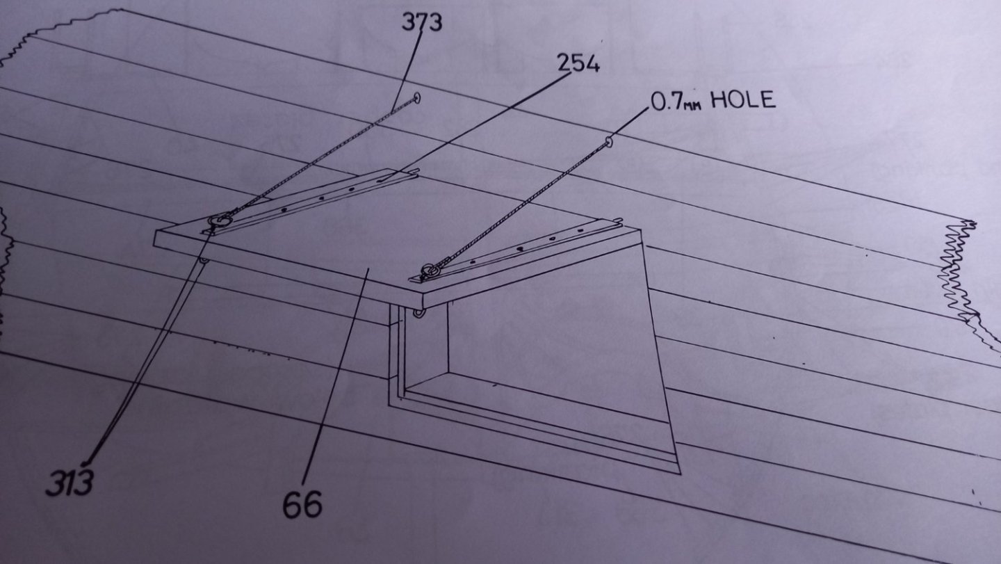
Allan I have some 0.5mm walnut so I could use that. However I have already cut the ports to take 1mm so unless I make the ports bigger than whats needed the guns barrels will not fit centrally. My initial idea is to fit the 1mm lining and then when I fit the final layer of planking leave a 0.6mm lip on sides and bottom which is what it looks like on the drawing. Although you will see a 1mm edge of the hull planking you will hopefully only see 0.6mm of the edge of the linings .I think this is what is also suggested by Caldercraft in their drawing below Thank you again for all your help and some very good alternative ideas. Best regards Dave
-
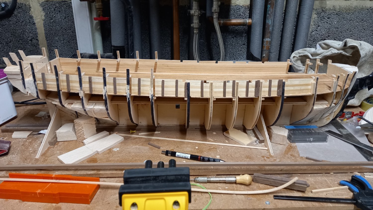
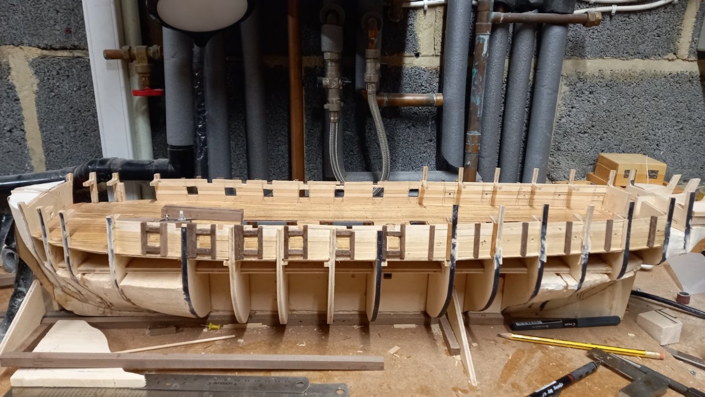
Oh dear! Caldercraft instruct the linings as 1 mm thick . So 0.6 is going to throw my calculations out a bit. The only way I can get at 0.6mm is to make a lip somewhere near the 0.6. I don't think the inside matters too much as it will all be painted red orche so will not be seen too much. I also forgot to make the bottom plank on the inside thicker for the spirketting so I am thinking of adding 8mm x 1mm wood which wood come up to the bottom of the gun port( this can clearly be seen on one of the photos you added Allan. What I can,t work out is do I need to add a waterway as well as the spirketing as I have already fitted a margin plank. I think I need a waterway as there are also scuppers to add too. Hopefully this will all look ok when finished. Hopefully all will look ok, even though I have already made a couple of mistakes. Progress so far Good job you are keeping an eye on my progress which is really appreciated. Best regards Dave
-
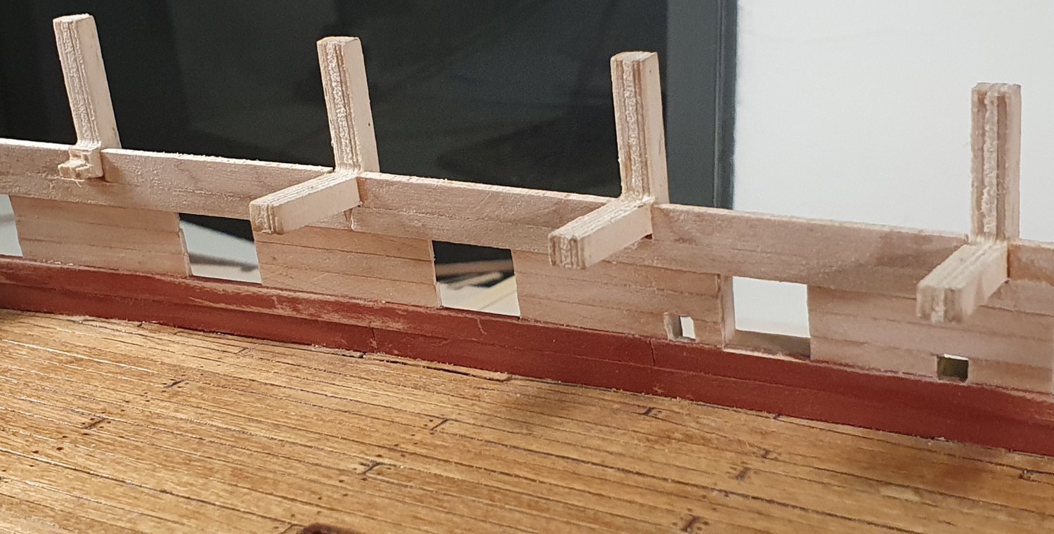
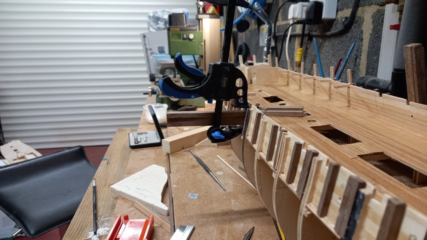
Thanks Allan that is pretty much what I have just done and it has worked out pretty well for the first part any way. I also made a piece of wood now 15 mm high. I used this small cutting tool to ensure the bottom edge followed the deck and then fitted the bottom support and then used the piece of wood 15mm high as a template , so the top support would be parallel to the bottom support. The sides are parallel to the buklheads ( simulating frames) and not the water line. I think it has worked out pretty well so far. After the sides were drilled with small holes. I found the knife was better for shaving the wood off the inside of the frame, especially in the corners and using the wood frame as a guide for the knife Just another 23 ports to go and fit the liners next . T Thanks also for the drawing, which has confirms what I need to do. Best regards Dave


-
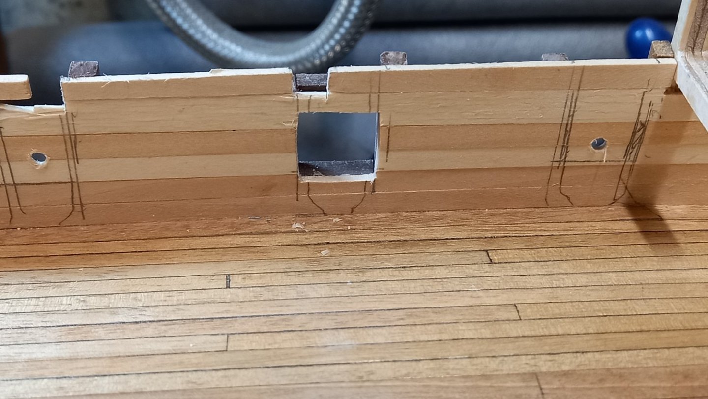
Thank you Allan for posting that perfectly timed photo which clearly shows the linings. I am now going to need to re think as I thought the lining would cover up a multitude of sins before adding the final layer of planking and would need to change my measurements too. I will need to fit a spacer inside the gap so will think about adding before starting on the first layer of outboard planking. I have already started adding vertical uprights on the Stb side but these are for strength only which I thought I would need whilst drilling and filing the ports.. II can also see from your photo that there is clearly a lip on the sides and bottom of the gun port and what is a very beautiful model too. Thank you one again.Best regards dave

-
Thank you again Jason for adding some more photos of frigates and I don,t think I will worry too much now about the gun port lids but I might add the ones if I find they are not going to foul anything else as I think in the right place they would look good. It would be interesting to know what other modellers have done with their frigates and the Diana in particular. For what it is worth the AOTS Diana has the aft 6 ports fitted with gunport lids and in the closed position and also the forward 2 . So it seems there is some evidence that these were possibly used or could this be a mistake. I don,t want to dwell on this too much more although I will be looking at different frigates a bit more closely in the future. Thank you guys for taking your time up adding your thoughts it is always appreciated. Best regards dave
-
I thought Ropes of scale made some nice stuff. This will set off your excellent model even more. She definitely deserves some good quality rope David.
- 310 replies
-
- 2
-

-
- Diana
- Caldercraft
- (and 1 more)
-
No Worries Chris all part of the learning curve. It has Definately got the grey matter working. Thank you Gregory for the excellent photo clearly showing no lids . However I have just seen a photo where the 3 gun ports aft heve and the one forward with 8 all together, but now O can't find the thing. Oh well. I will keep looking and see if it turns up and will put it on here.
-
Thank you Gregory for your input which is interesting. I assume the weather deck is the upper open deck on the Diana . It is the lower deck that I now understand has only 8 of the 28 gun ports that have lids or at least on the model it does. This is what I could not understand. Up until now I thought all enclosed gun decks had all their gun ports with lids. I am assuming an enclosed deck still has ventelation holes and hatch openings. I would be grateful if you would clarify if any of the above is not the case Thank you again.Best regards Dave
-
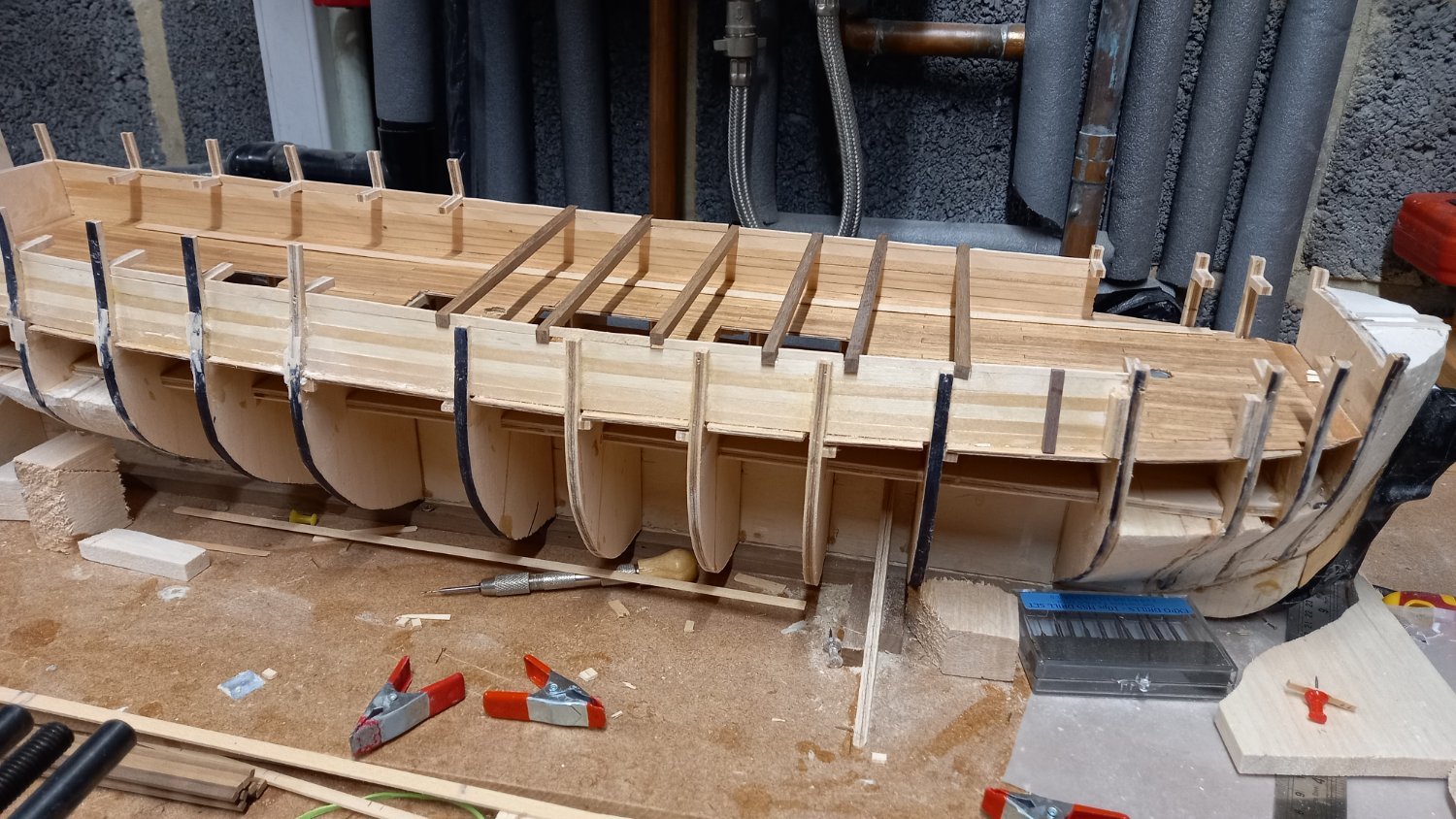
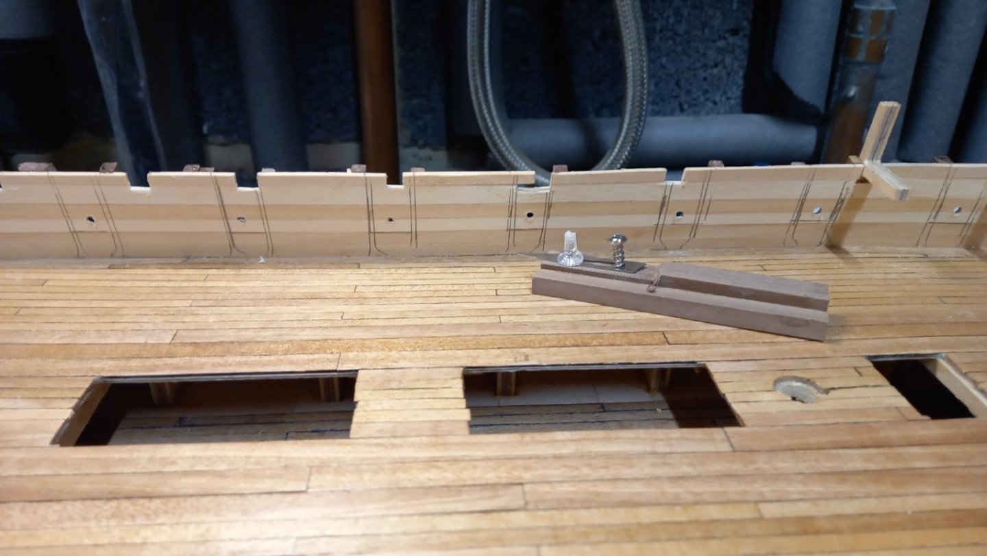
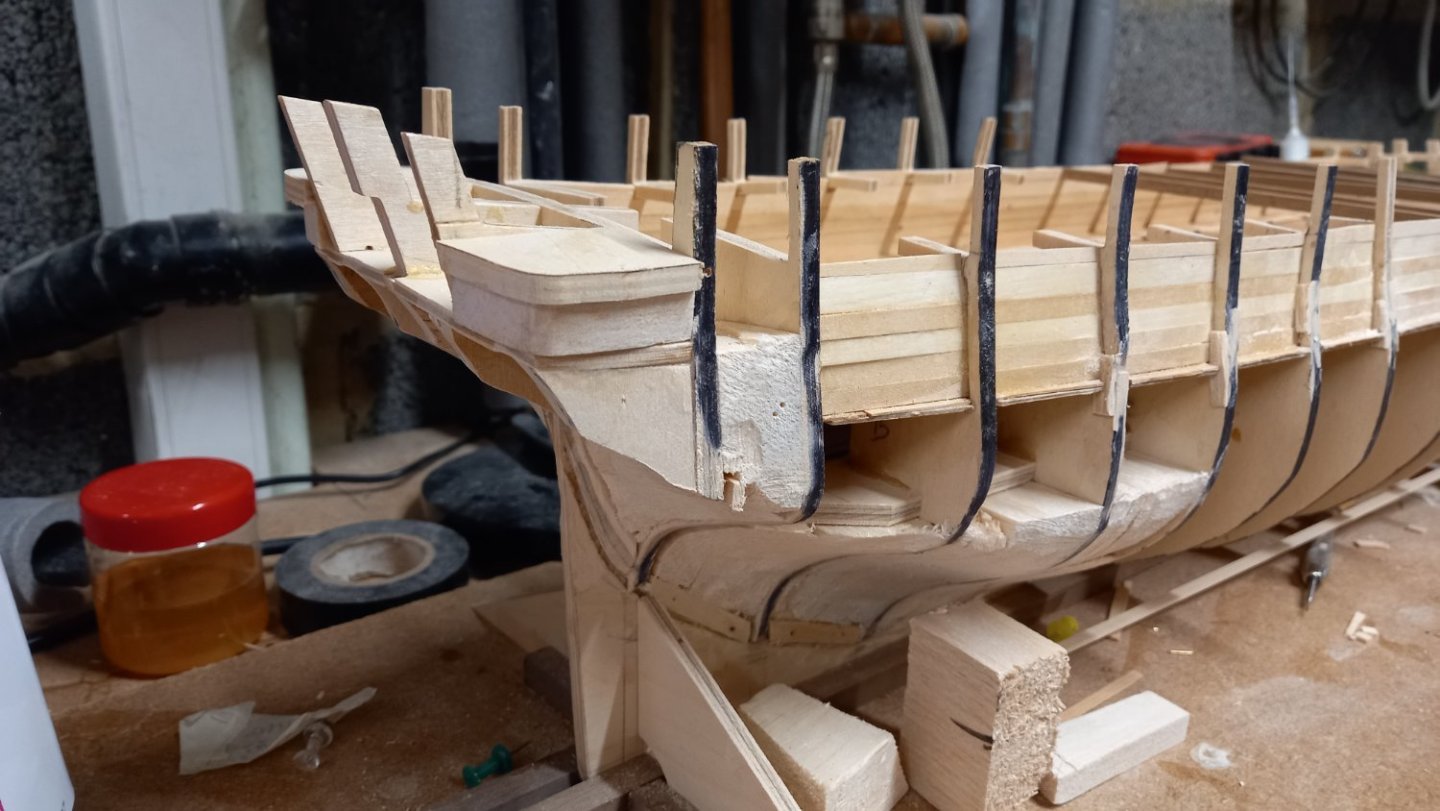
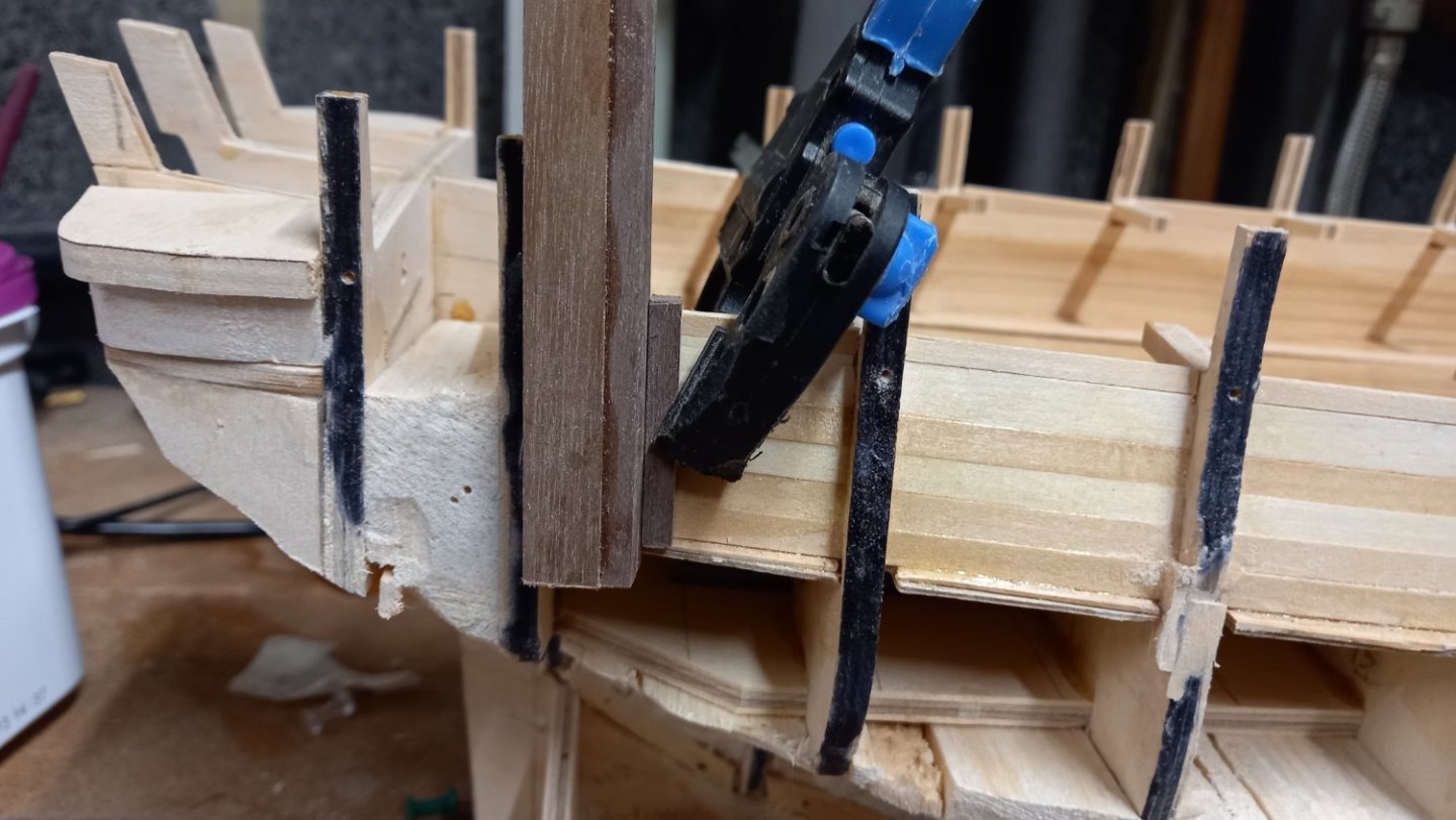
I have cut out the recession the inner Hull for the 4mm beams for boat supports More thoughts on Gun ports and there lids. I am unsure why there are only 8 lids but there must be a simple answer to this. The lids measure 14mm x 12mm which after lining the 16mm x 14mm hole with 1mm think walnut this would be correct. However if I wish to line the gunport with o.5mm I am unsure to make the hole smaller or the lids bigger. The lids are supposed to lie flush with the hull. The second layer of planking is 1mm thick and the lids are 1.5mm thick, so I will need to recess the lining 0.5mm but this sounds a bit tricky to me. As this ships first planking is lime and not walnut although this is easier to bend I Don t think it is as strong. I therefore thought about some additional upright frames 14mm apart to strengthen the hull planking whilst cutting the gunports. This is a similar idea to DaveEN approach who fitted the linings prior to the outside Hull planking. Nice idea Dave. I am still thinking of some sort of frame to get the correct height from the deck. Perhaps I should have considered planking throughout with walnut. Here is the jig for fitting the frames either side of the gunports .

-
Thank you to everyone who has contributed to this fascinating thread. I can only guess as to what great change was made during the 18th and 19th centuaries right up until the launch of a ship and also afterwards in refits etc and at other periods too. I have indeed wondered why some people suggest that in some modern documentation there are possible mistakes and if some model manufacturers take this as being gospel as did I myself. Next up is for me, are gun ports and their lids. However I will leave that for the time being as there is already a lot of information on this forum to search through. Anyway thank you once again . Best regards Dave Baxter.