HOLIDAY DONATION DRIVE - SUPPORT MSW - DO YOUR PART TO KEEP THIS GREAT FORUM GOING! (Only 51 donations so far out of 49,000 members - C'mon guys!)
×


DaveBaxt
-
Posts
1,324 -
Joined
-
Last visited
Content Type
Profiles
Forums
Gallery
Events
Everything posted by DaveBaxt
-
Well done david with those pesky CC deadeye wire strops. I had the same problem with them on my Endeavour build. I like your idea of using a polystyrene block and pinning them to get the correct distance apart. I used a similar idea which but made jigs instead of the polystyrene. I think the next time I do the lower chain plates I will end up soldering them. Good luck you are going great guns. Here is a photo of how I managed it . Not my initial idea,but it worked pretty well. Hope this helps.
-
Thanks to all for helping me out and I managed to get it going by clearing the Cookies. I will now need to buy something to check is all working OK. Haha .Best regards Dave.
-
Thank you mark and the rest of you for trying to help me out. I will give this another try.. Good to hear that its probably my end.
-
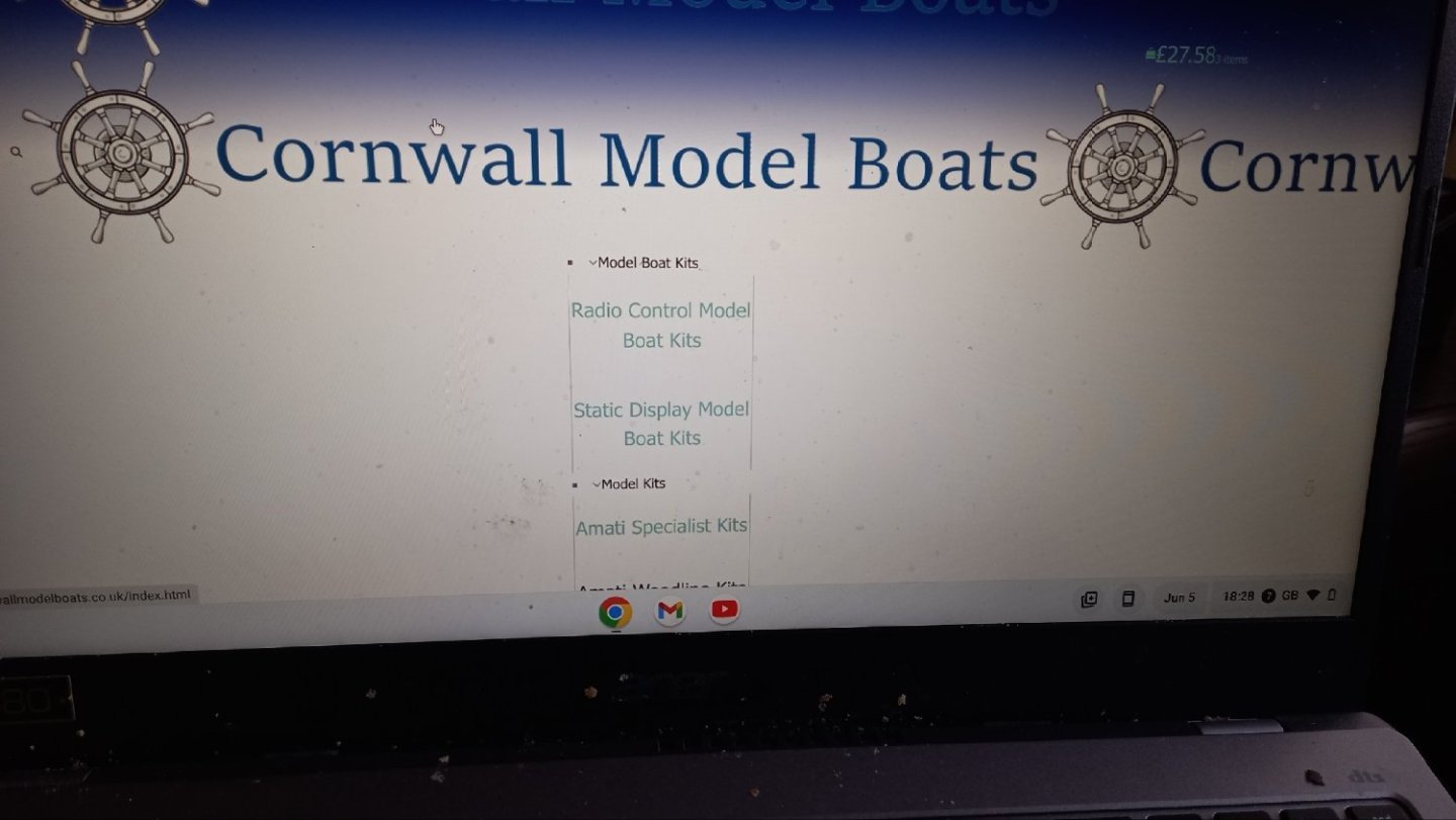
Tried your link and got the same page. Below is a photo of the page. Apart from the obvious difference the links Don,t work either. I might try Firefox or something other than chrome. Any other suggestions are welcome. TI have managed to open this up on my Android phone and get the same page, but I am able to navigate the site ok but not great on the phone but at least I can now contact them if need be..
-
Thanks guys Still not working on my Chrome Browser . I am getting a page up but the links don,t appear to be working. Hope this is not perminent. Hopefully this will be resolved soon as they are my main source of supply.
-
Anyone else have issues with their website? If so let us know as I think their site is currently down. Cheers
-
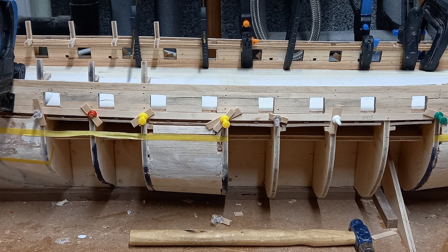
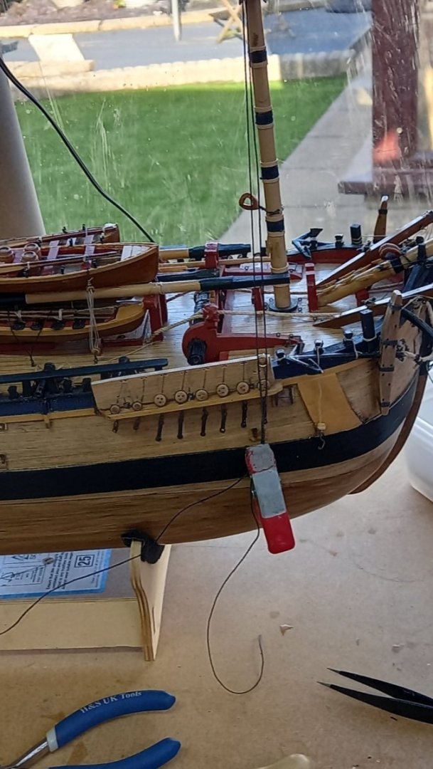
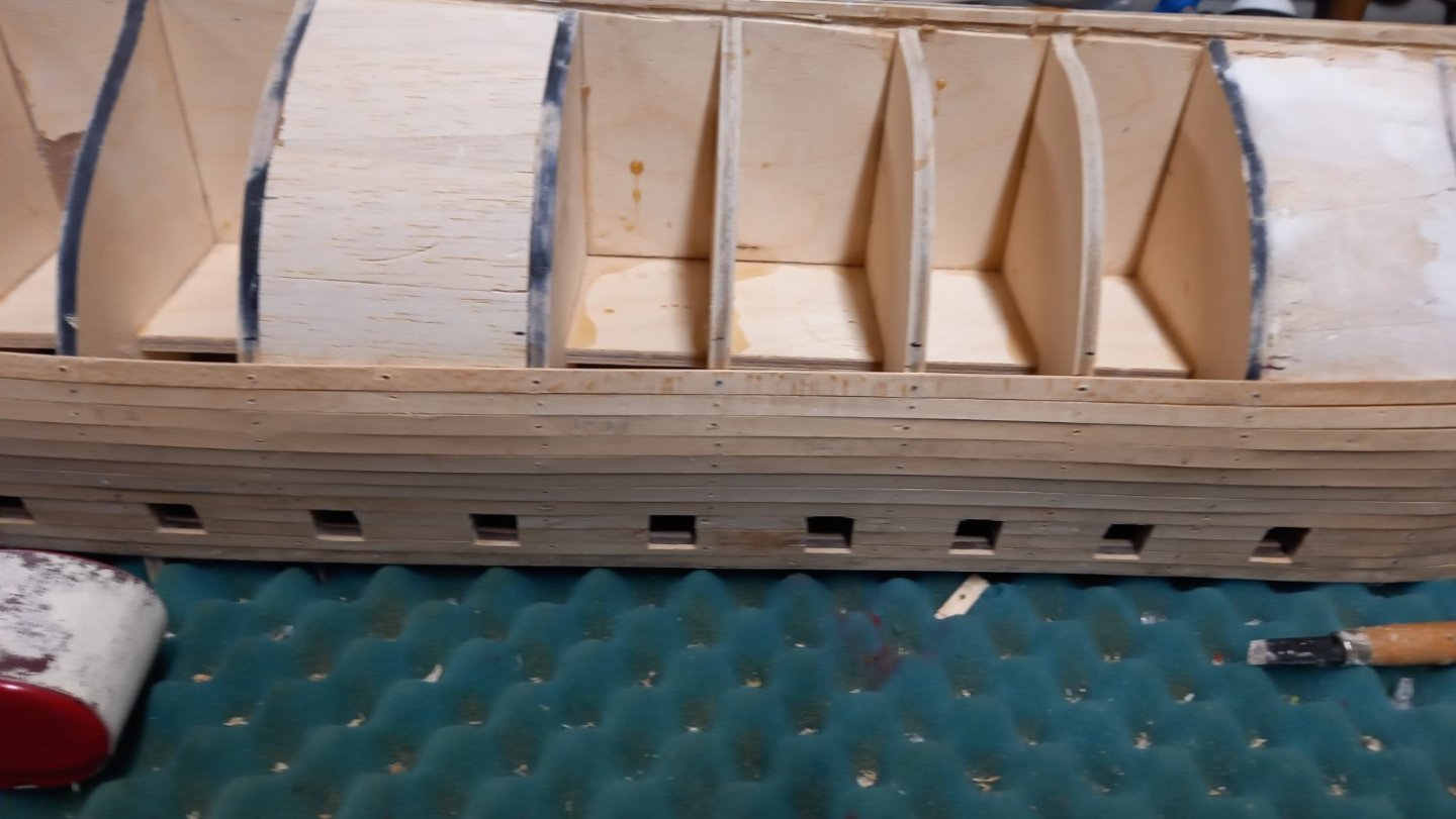
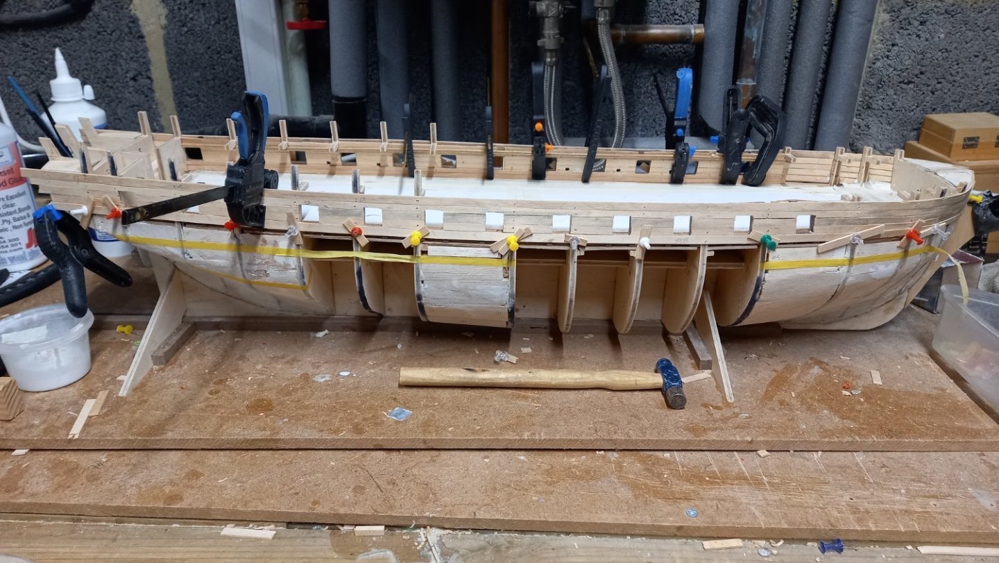
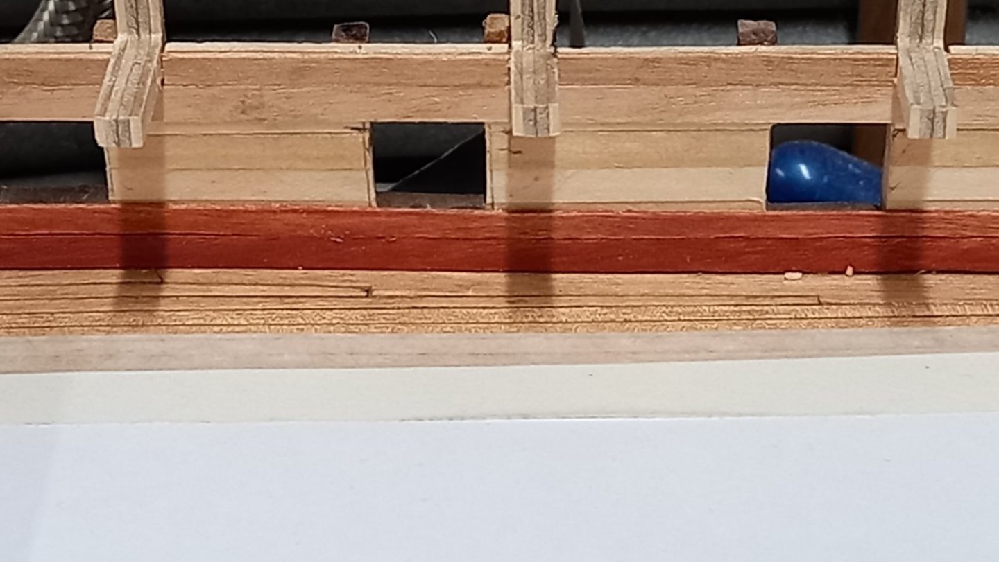
As I continue to add the first layer of lime planks to the final two zones currently the last 12 planks or so to lay before filling and sanding etc. I have been considering whether or not to have open or closed bulwarks. A fewt of the Diana builders have opted for the open bulwarks and this might show the 9Lb cannon and 32 Lb canonade of better bus as I don,t have any specific drawing with sizes, I might follow DavidEN's direction and go for the closed bulkheads. Next I need to cut the two forward gun ports out but before this I need to do a bit of work on the hull in this area as this did not come out as well as I had hoped when laying the planks. I now wish I had built this area up with supports and inner hull planking . Looks like I will need to order a bit more filler. Before I mark out the positions of the upper deck gun ports , I need to ensure that the aft gun port is clear of the quarter galleries and think it mught be easier to fit these first. Lots to think about and decide before actually removing any material. Using a template of the CC drawing rather than the supplied plywood templates seems to work out pretty well but will check this once again against the shrouds and gun port positions. Once I am happy with this then perhaps I can consider moving onto the second layer of planking. Hope I am making sense.

-
Welcome Sam. This is a great friendly and informative forum. The best out there!
-
That must be a huge order from Ropes of Scale and keeping him very busy. Any thoughts on making your own rope David ? Your rigging is looking very professional.
-
Thank you Mark
-
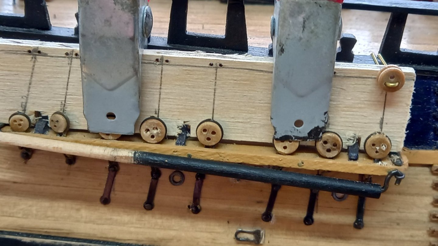
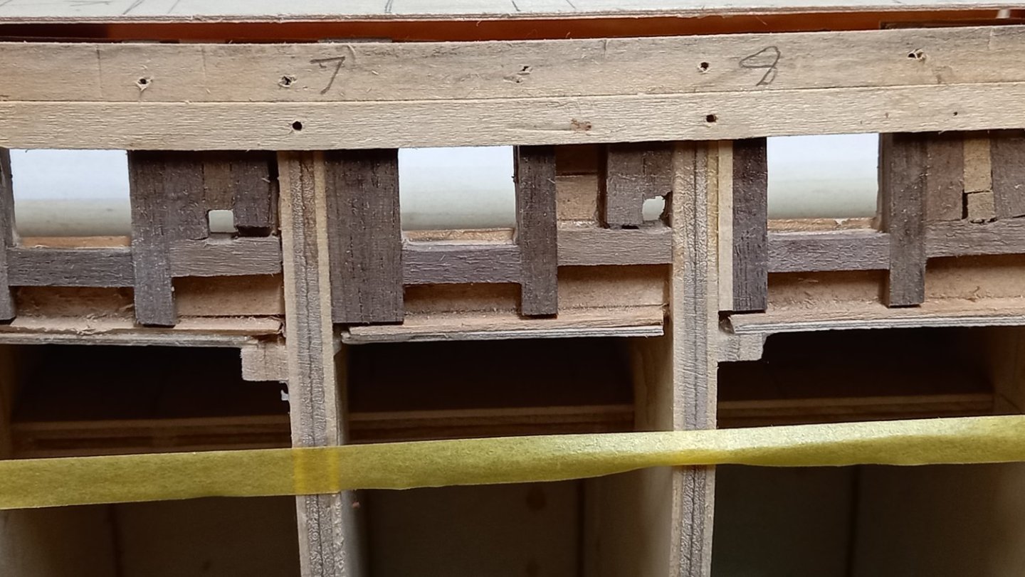
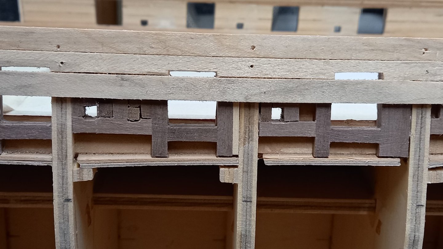
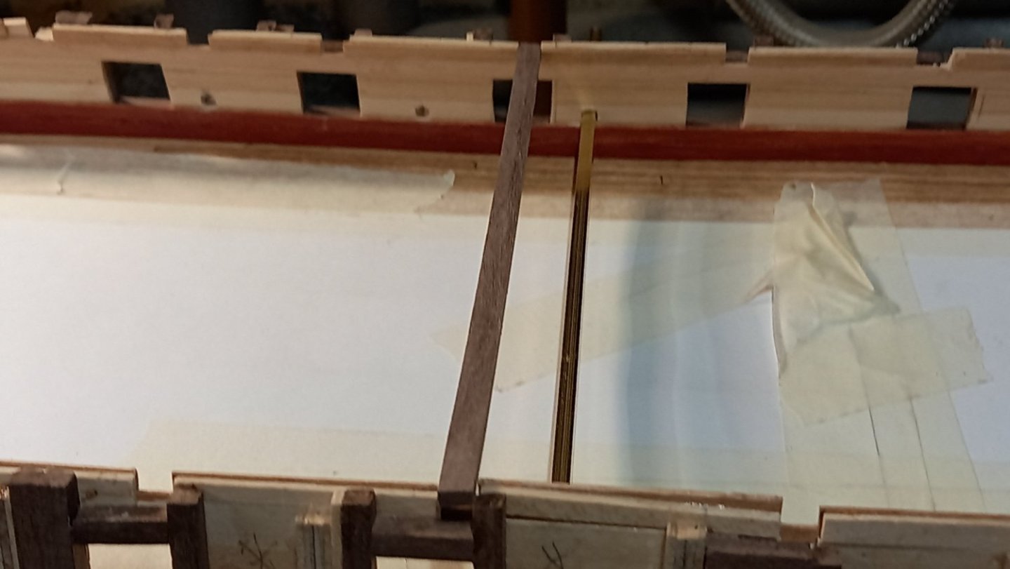
Gregory Thank you for the drawings which is similar to what is in the Goodwin book although a slightly different shape the idea is the same. It si interest what you have said regarding fitting a qtr round and would be easy to fit between the sperketting and the margin plank, I have made a piece which is concave and thought I would try that. However thak you for somewhat clearing that up for me which has giving me more confidence in fitting a water way. Best regards Dave
-
can these be fitted together or is one instead of the other. According to Goodwins book 'The Construction and Fitting of the Sailing Man of War 1650 to 1850' the waterway is fitten to create a water tight seal and protect the area from the ingress of water and cause the wood to rot. It is my thinking that even when the margin plank is fitted to an open deck it would still be necessary to have a water way fitted at the same time. I cannot find evidence of whether or not this is the case for the Frigate HMS Diana on the lower gun deck which is open to the elements or any other ship with similar deck Hope this makes sense. Thank you and Best regards Dave
-
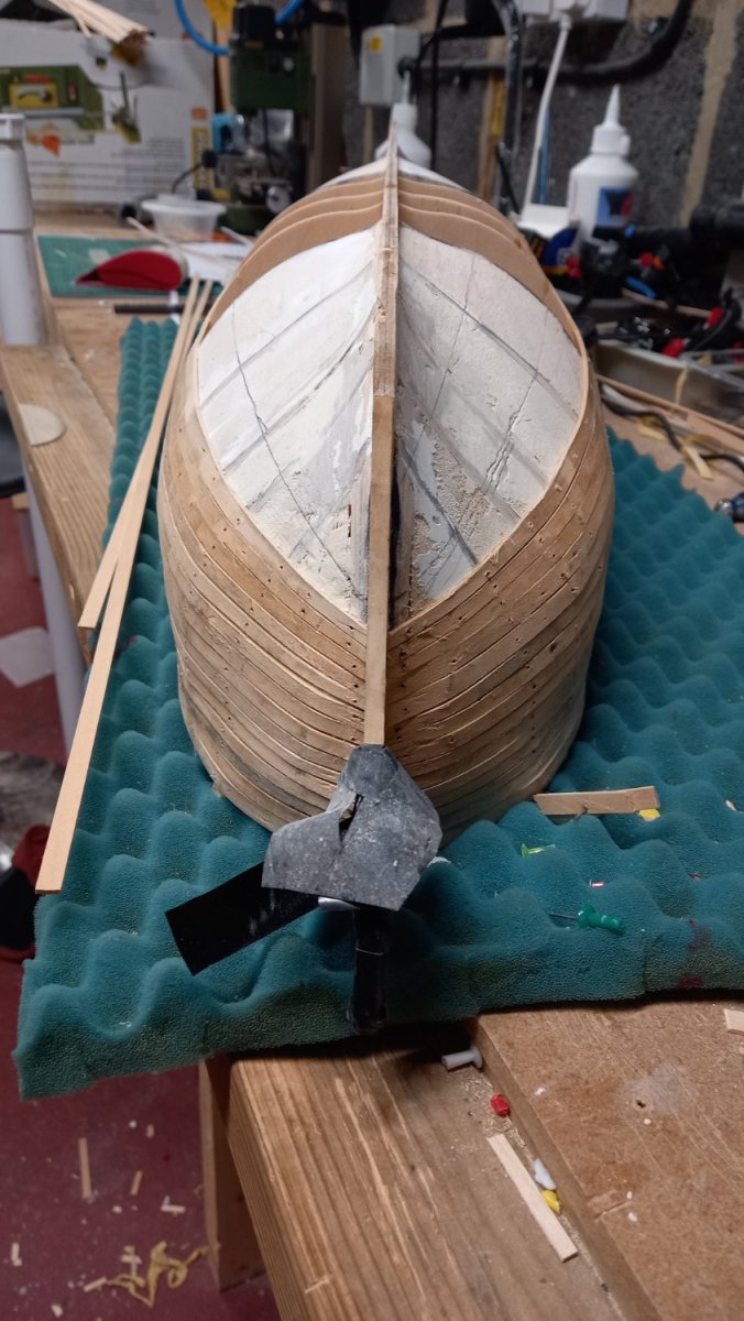
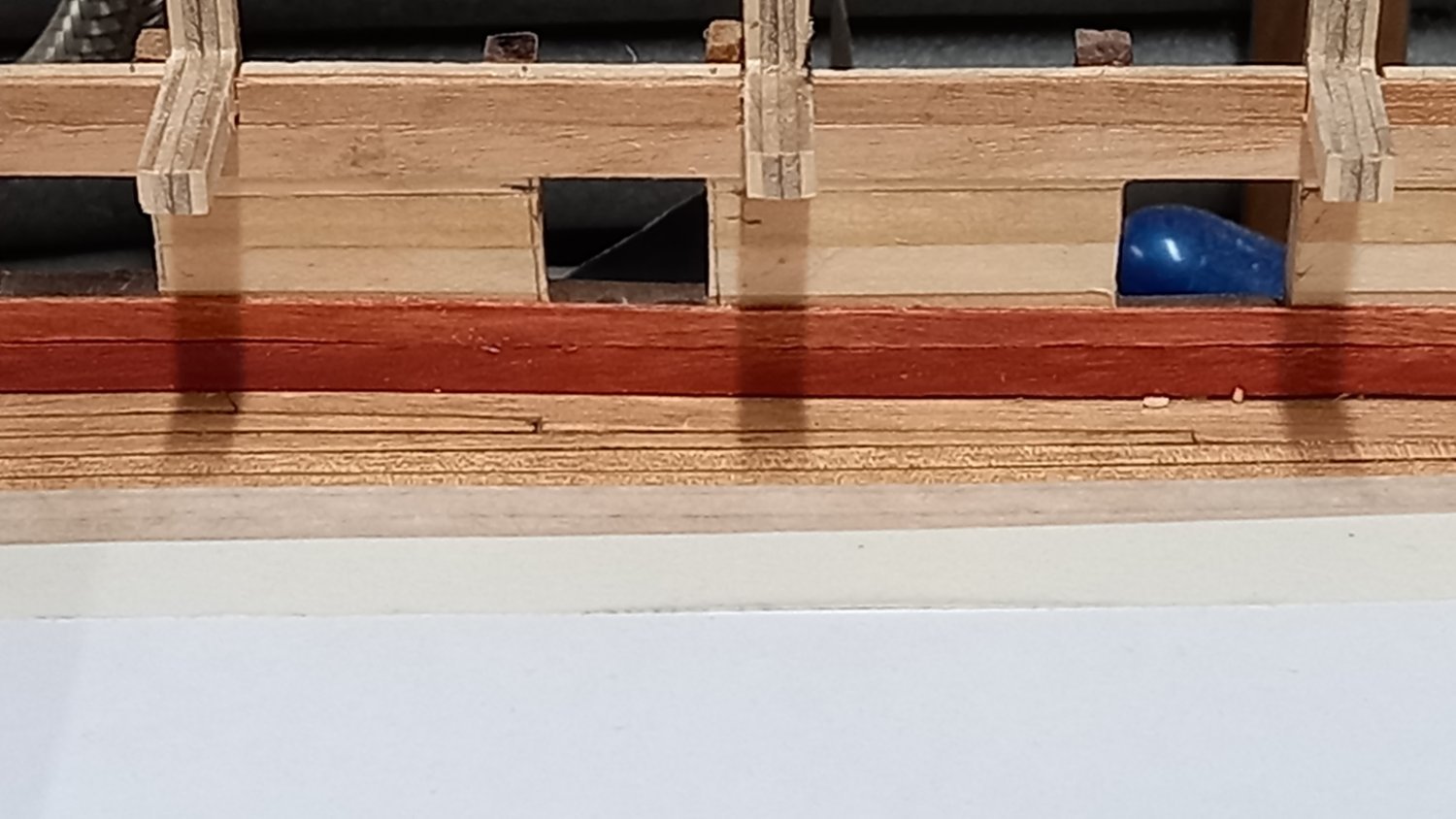
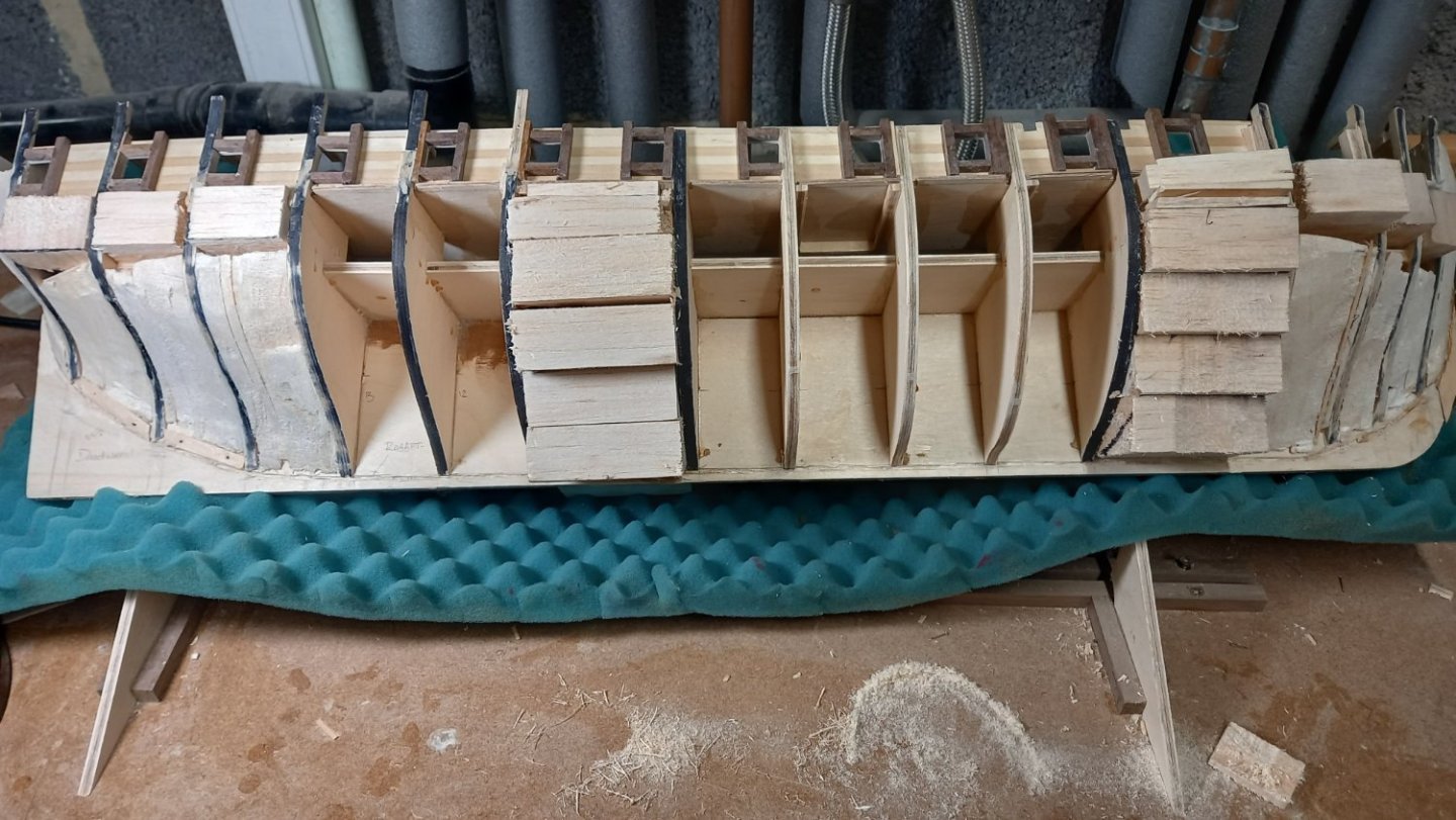
1st Layer of planking (Lime) I made a start on the first layer of planking 1.5mm x 6mm of lime which is very soft but easy to work with. I used Chucks method of edge bending but it always takes me a couple of planks to get into the swing of it. I Also decided to lay the planks the full length and then cut out the gun ports as I go. This worked quite well but there is one or two areas which hopefully will be hidden one the gun port linings are fitted and sanded flush with the hull. In hind rsite I now wish I had left the sperketting off until after I fitted the liners as it would have been easier to sand them flush on the inside. It was important to lay the first plank level with the upper deck so this was temporarily fitted to ensure this was done. I also marked of the hull into 5 zones , each zone comprising of 6 planks. I also used a spare plank to see where each zone ended and tapered each plank accordingly. I hope this worksout ok.

-
Some great looking rope you have there David and your tackle is of a very good standard. You are a natural and I look forward to you moving onto the shrouds.
-
Fantastic looking Sphinx Mark. Sorry I have not been here lately. The blue and gold paint work is absolutely amazing and you are obviously very artistic. Keep up the good work and I look forward to seeing your progress.
- 505 replies
-
- 7
-

-
- vanguard models
- Sphinx
- (and 1 more)
-
Looks like a really precise piece of kit that Mark. I have the Proxxon table sander it does the job but the table isn t great and the angles are not very precise. Keep up the excellent work Mark.
-
Thank you for your input Mark. I have seen some videos regarding making your own chisels which are around somewhere which shows exactly what you are talking about and it is a credit to you if you have achieved this. I will see if I can find the videos and will post these here for anyone who wants to give this a try.
-
Thanks Dave, I have seen these dockyard tools you speak of somwhere and look good, so always good to get the heads up on them so thank you for your input. Best regards Dave
-
Thank you Keith. I emailed this guy a while ago and his reply was that he would make as set for me but unfortunately he is unable to get them outside of Russia. At least to the UK and Europe I believe. This is due to the conflict and the sanctions currently imposed on Russia. I think they would probably be out of my price range too.Thank you for the Link though Keith as there is some interesting and helpful information on there. Best regards dave
-
Sorry if this has been discussed a number of times before. I am looking for a small set of micro carving tools for carving scrolls at the end of the rail, trim etc. I came across a couple of Flexcut carving tools with what I hope would happily do the job and includes a number of different types of blade. Here is one i have been looking at :- https://www.hobbies.co.uk/flexcut-1-5mm-mixed-profile-micro-tool-set-6-piece?utm_source=google&utm_medium=cpc&utm_campaignid=19833019814&utm_campaign=&utm_term=&adid=&addisttype=xpla&matchtype=&gclid=Cj0KCQjwyLGjBhDKARIsAFRNgW-ZCDKYBd4QxkAjMvlM1f6v8yNLmZ-kIrQktZJoDMp4vvin9Gd_sBQaArE3EALw_wcB Which for the price is about as much as I would want to pay, however there are cheaper Flexcut options out thre with four pieces including 2 knives and 2 gouges.. Knives I am not sure would be worth getting as I have several different knives with optional blades. The cheaper Flexcut option is also less than half the price of the above link. Here is another set which price wise is somewhere between the two https://www.hobbies.co.uk/flexcut-beginner-palm-and-knife-set-kn600 Perhaps it would be better just buying one or two better tools and gradually build up a set. If there is such a make out there that is high quality and allows you to do this then any recommendations would be appreciated as would recommending which individual pieces to buy first. Any different makes of micro hand carving sets which are recomennded would also be appreciated. Best Regards Dave
-
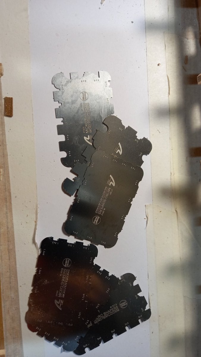
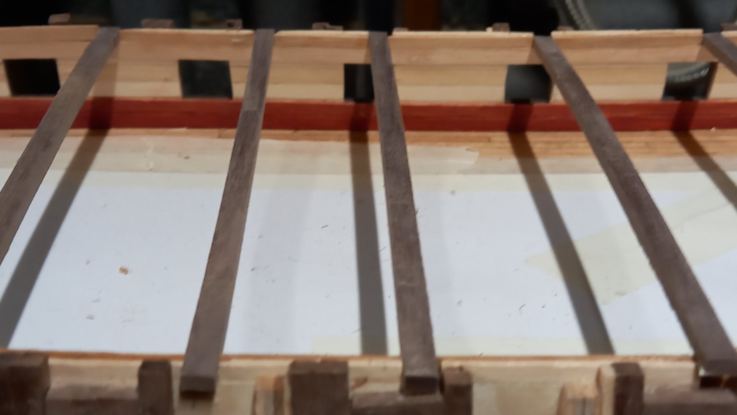
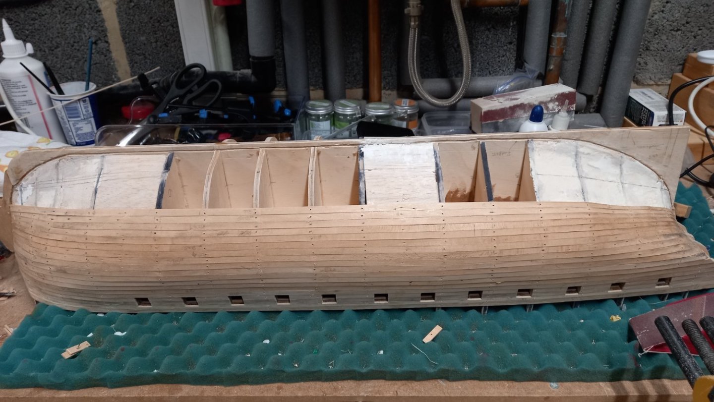
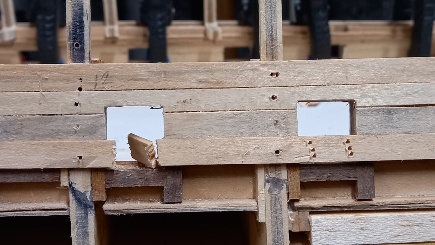
Tested out Shapers just received from Artesania Latina and made up the Skid beam clamps which worked out reasonably well on walnut, however for any trim on the outside of the hull I will try and use Boxwood. I have only a couple of sizes in boxwood for making the trim 2.7 x 2.7mm and 1 mm square . However i have lots of different sezes in walnut. On this occation I used 2 x 3 mm which was the size of the shaper I used. I now just need to make up the top riders and then considering aiir brushing the internal hull planking but wondering if anything else needs gluing to the internal walls first. I have had to re-position a pair of the oar ports as I put them in the wrong place. Almost ready for the first layer of hull planking after some more fairing of the bulkheads and the balsa wood blocks.


-
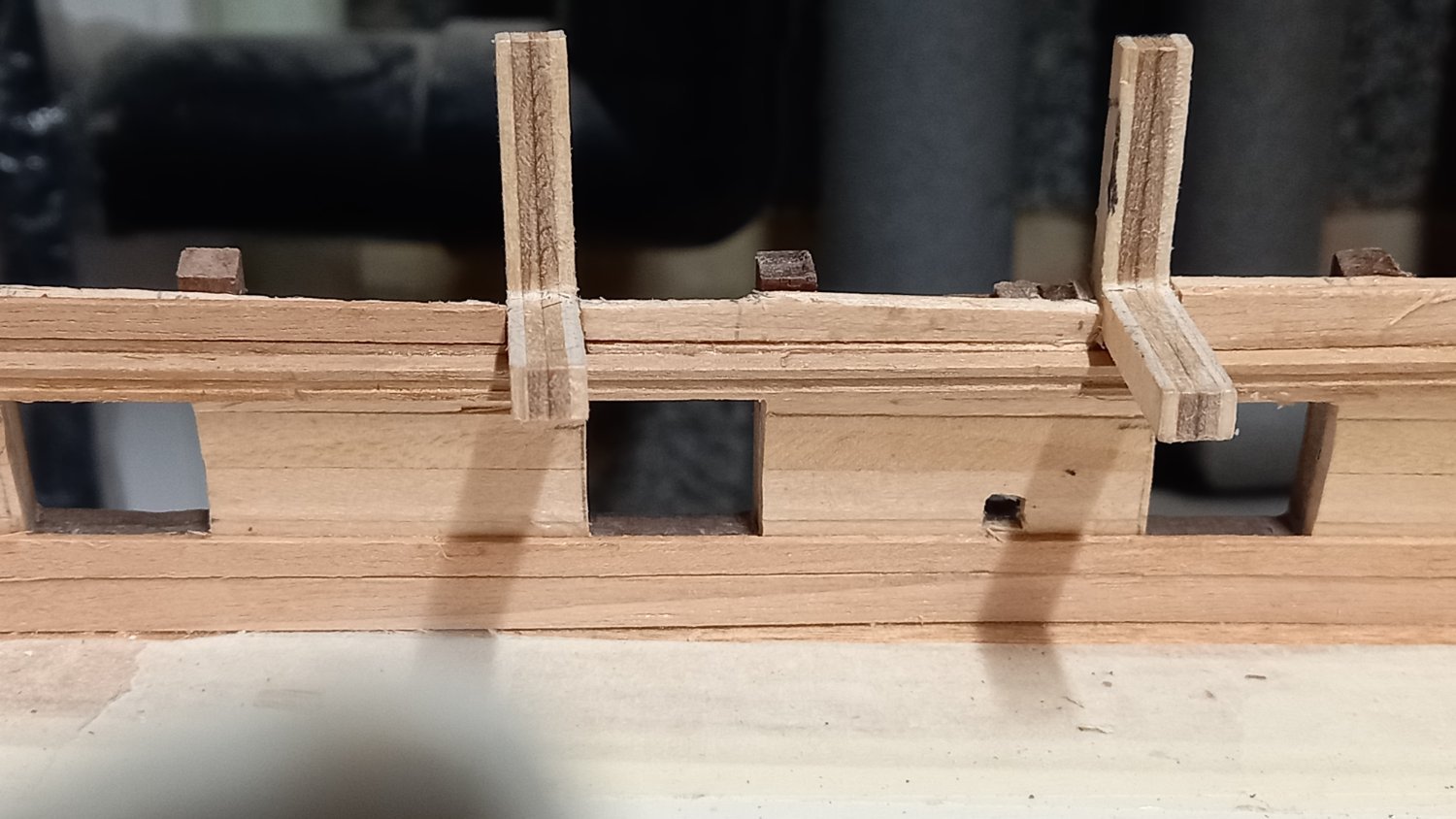
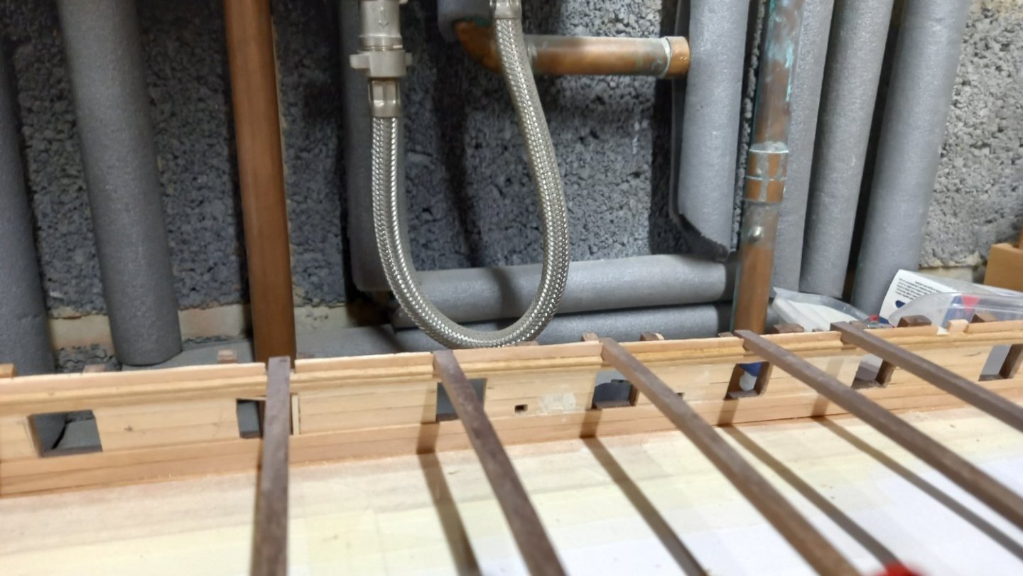
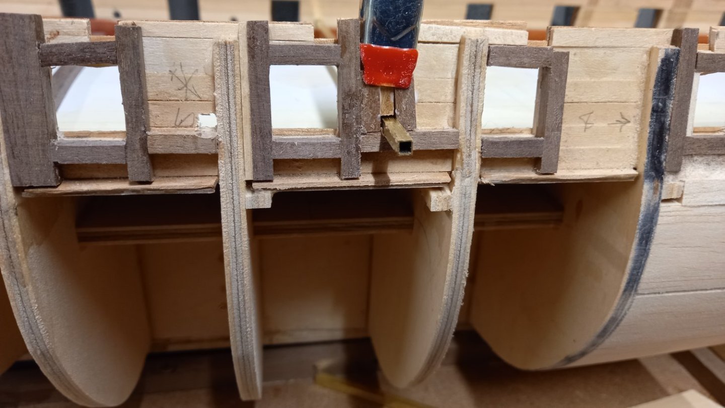
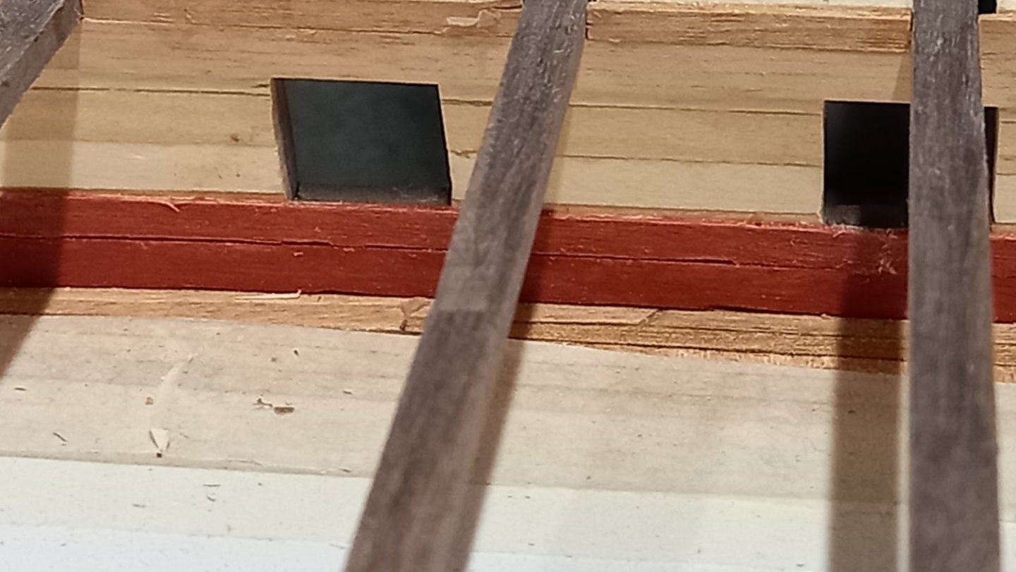
Worked on oar ports which are not on the CC drawings so used the AOTS for reference which gives them as 3.5mm. I am unsure if these are lined with wood of which I could use 0.5mm walnut and make the initial holes bigger but I am considering using 3x3 mm brass tube which I could paint.I think either would look ok. I have also built up around the oar port similar to what I did with the inside of the gun port. This is so I have something to glue to when planking the hull. It should give additional strength too.
-
I really missed this site after only a few hours . It kind of went hand in hand with my cup of coffee. A big thank you to the technical guys or who ever brought it back to us. Well Done.
- 24 replies
-
- 18
-
-
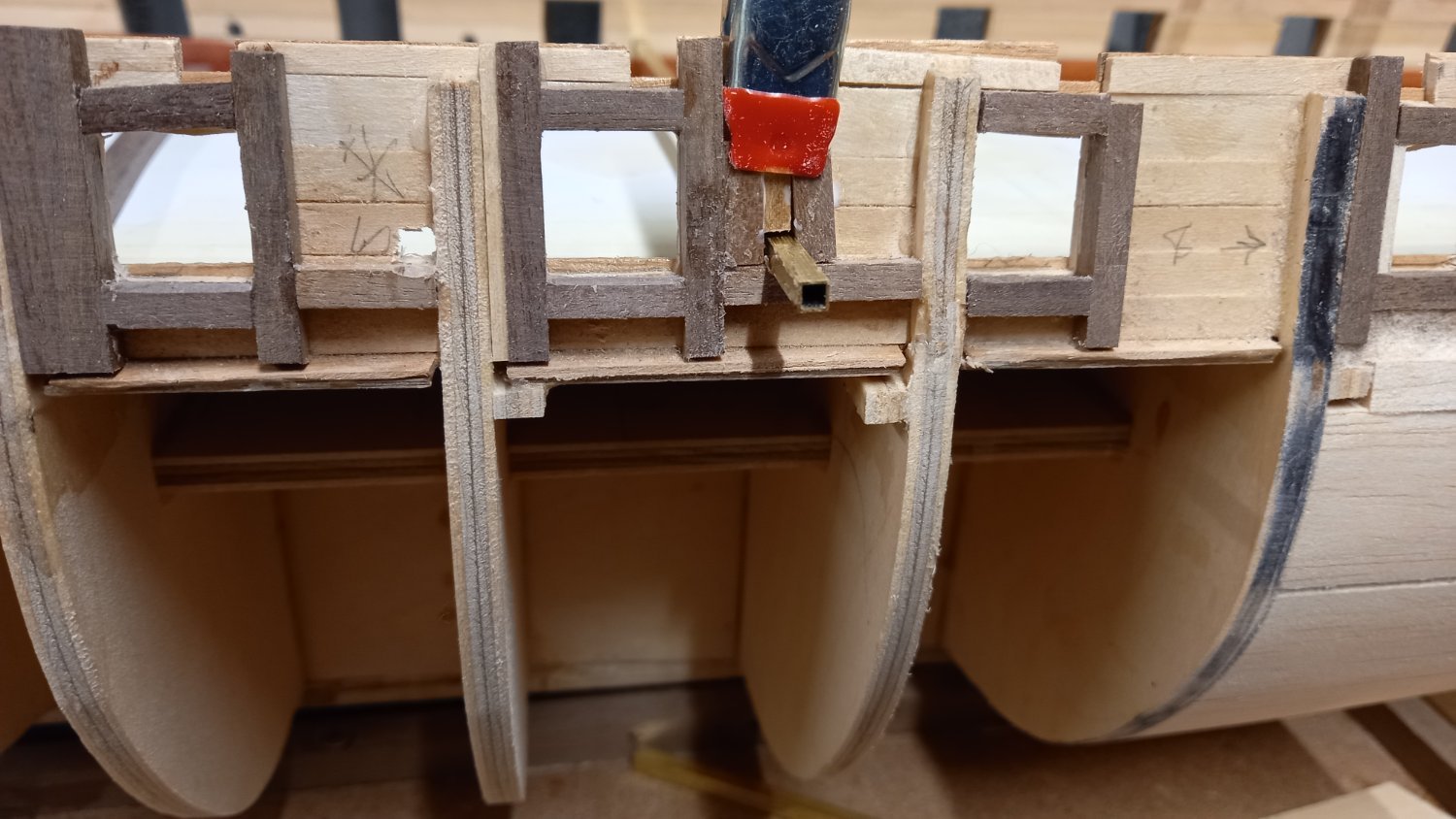
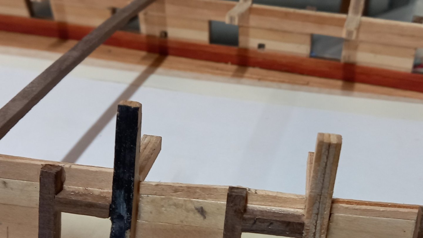
Before I carried on with the inner hull and fitting of 1mm thick planking to simulate spiketting and the deck clamps( next time I do this Iwill fit thicker planking.) I decided to fit some extra balsa wood blocks in areas where there was a large distance between bulkheads. I think this area required strengthening One thing which I am still unsure about is whether or not a waterway is fitted. Again this is something which should have been fitted earlier. As I have already finished the deck planks and incorporated a margin plank can I also fit something that would simulate a water way. I can see from Goodwins book that a water way is fitted as a watertight seal to prevent water entering this area to prevent rot so I think there would be one and will see if I can fasion something after I have fitted the top riders .

-
Decorative trim/rail
DaveBaxt replied to DaveBaxt's topic in Building, Framing, Planking and plating a ships hull and deck
Here is a link to Beef wellingtons log of the HMS Diana page 26, where he gives links to the Dremel Diamond cutting wheel and the safety razor blades required to make your own shapers. He has had excellent results working on the trim. Hope this helps.