HOLIDAY DONATION DRIVE - SUPPORT MSW - DO YOUR PART TO KEEP THIS GREAT FORUM GOING! (83 donations so far out of 49,000 members - C'mon guys!)
×


DaveBaxt
-
Posts
1,324 -
Joined
-
Last visited
Content Type
Profiles
Forums
Gallery
Events
Everything posted by DaveBaxt
-
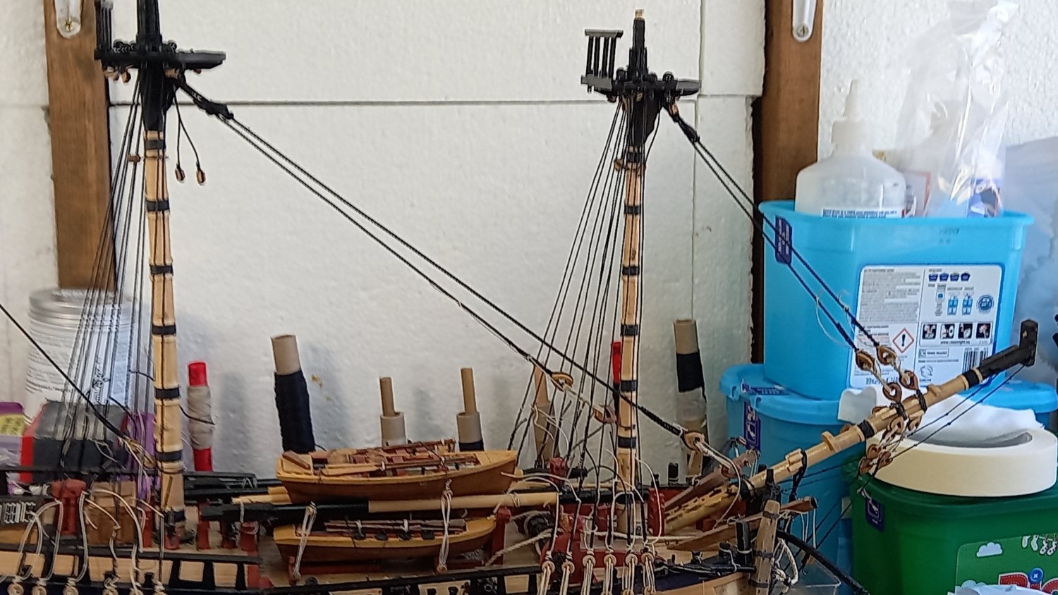
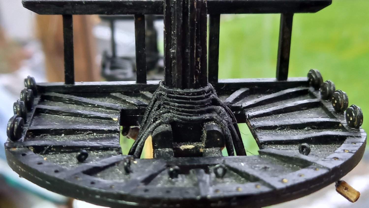
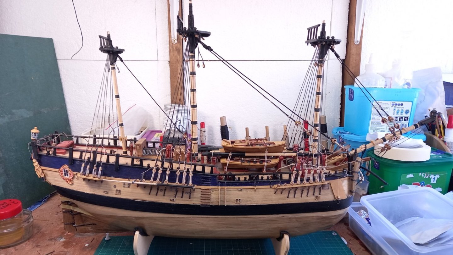
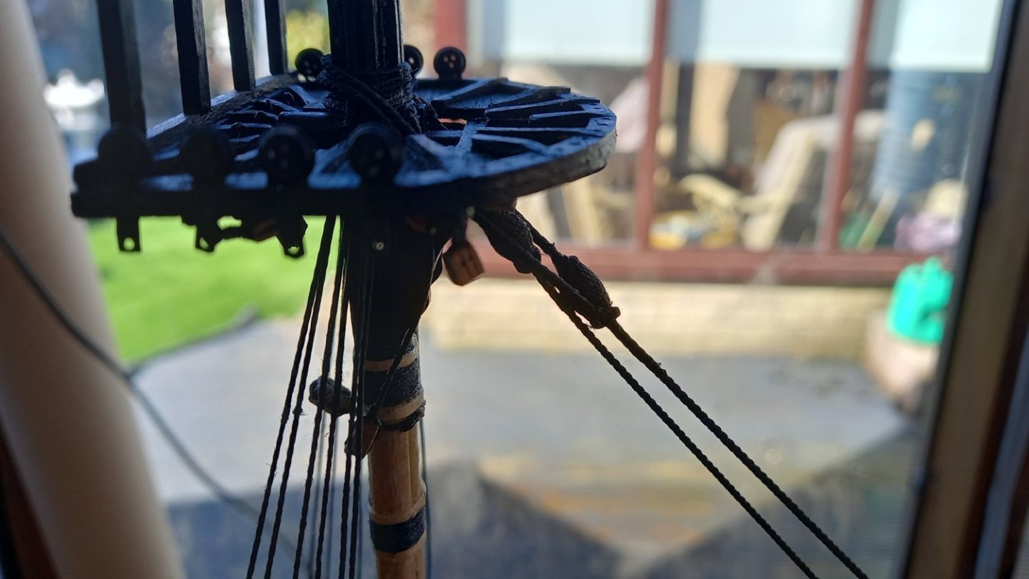
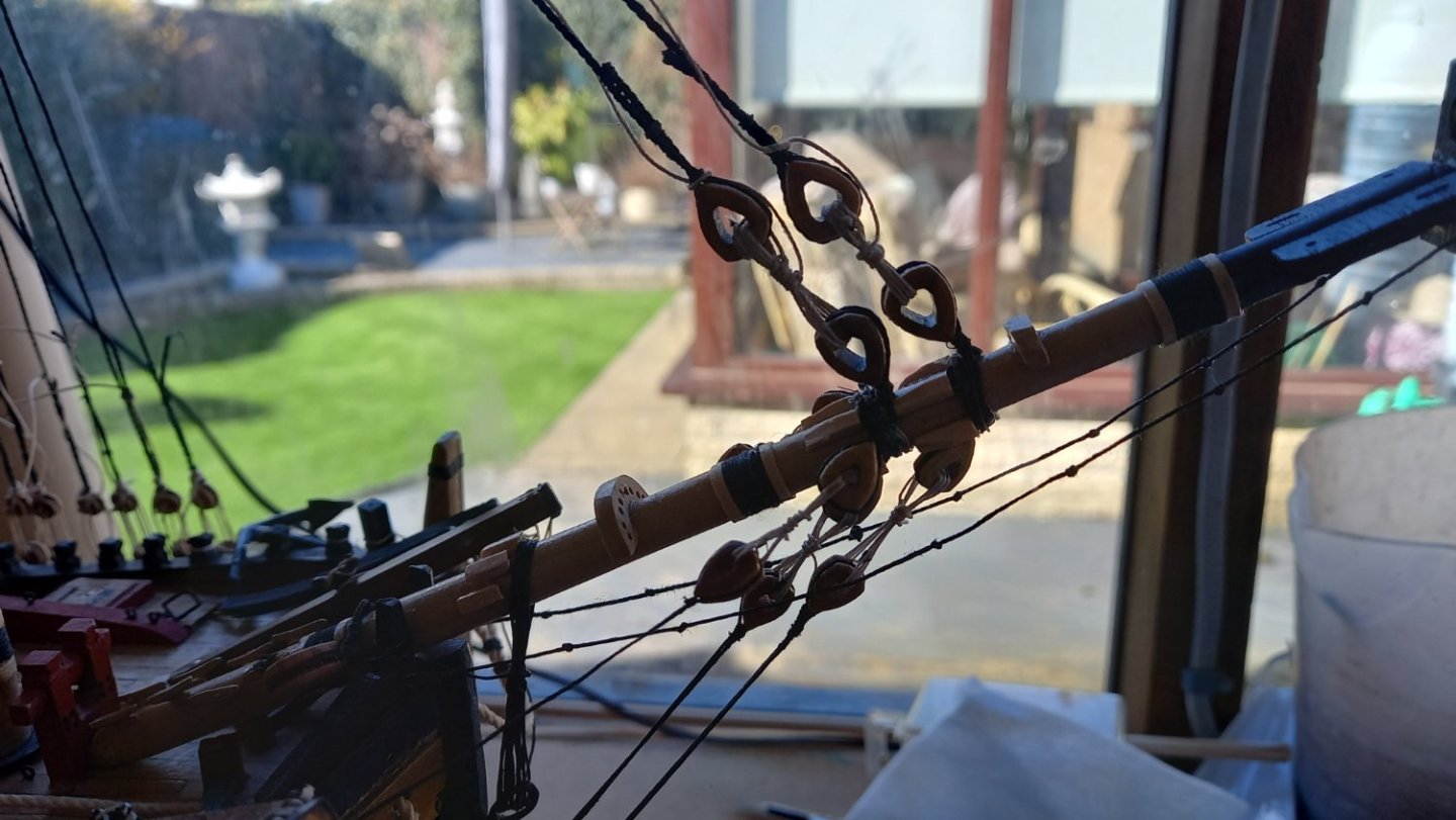
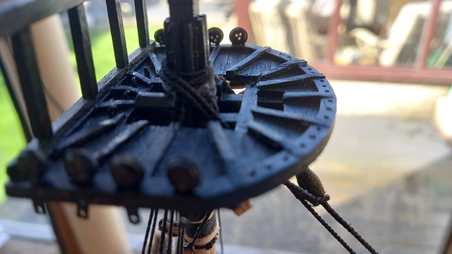
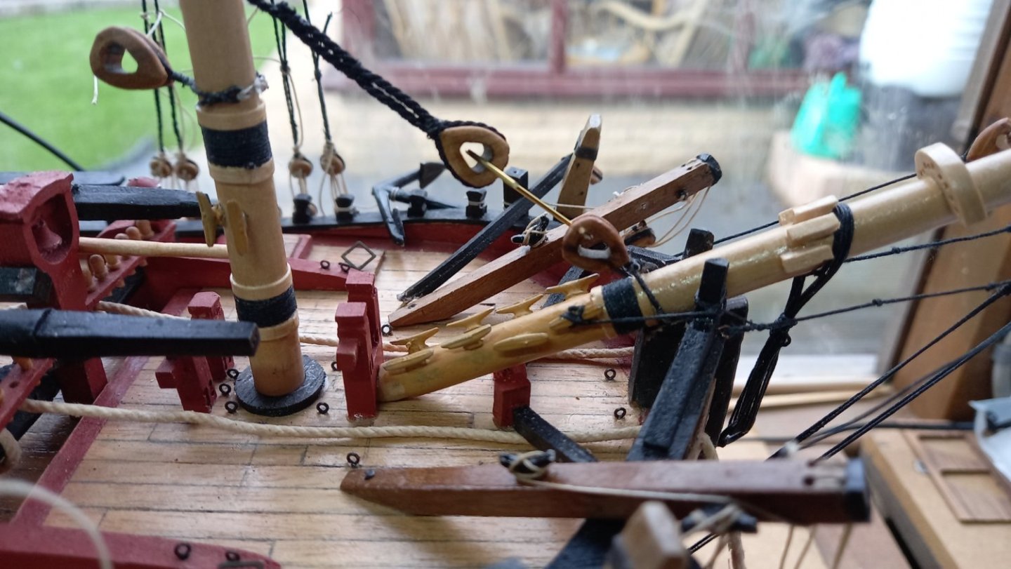
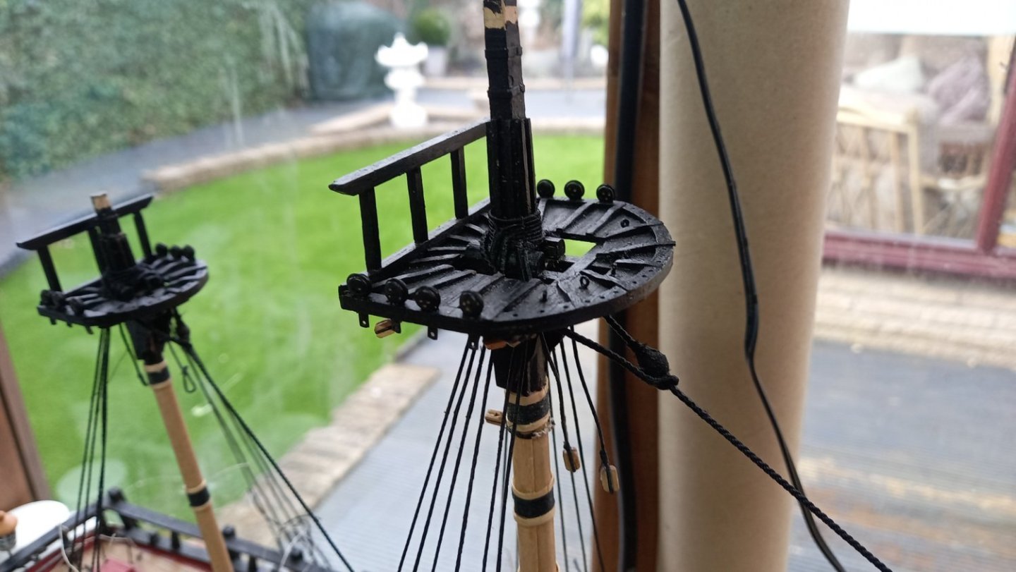
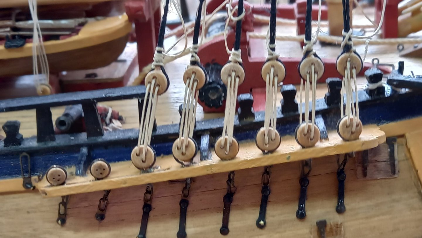
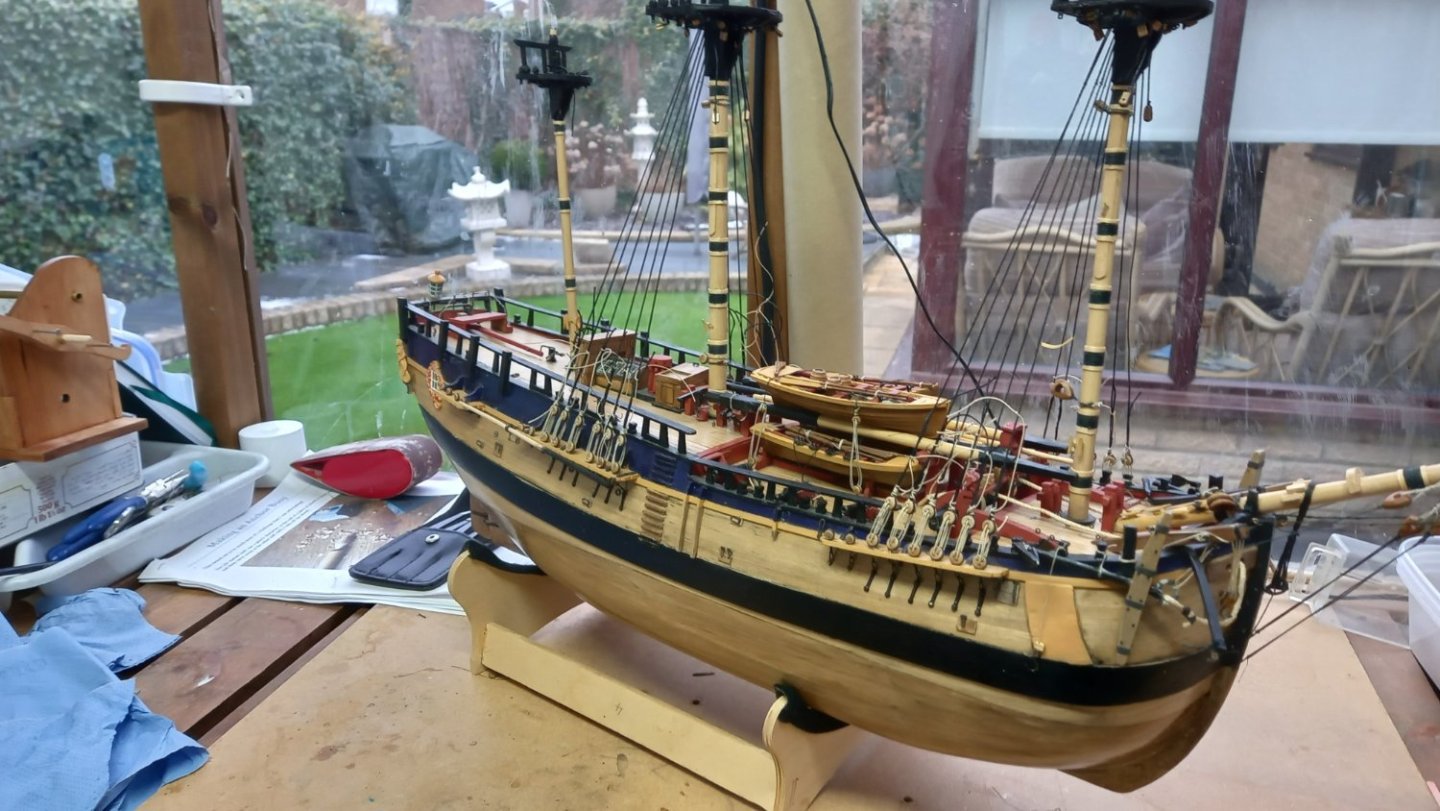
Lower Stays completed . I have fitted the Main & Fore lower Stays on top of the Preventer stays as per the Endeavour replica. Also Lees book states that a lot of small ships during this period carried the stays this way too. I think I will now adjust the tension on the lower shrouds before fitting the futtock shrouds and then the upper shrouds can be fitted before the upper stays and back stays are fitted. Here are a few more photos of the work so far. I also need to do a bit of work on the top masts and lower mast heads before the top masts are fitted.
.thumb.jpg.5a9000d230130397d4c5b79ad39ea0ad.jpg)

-
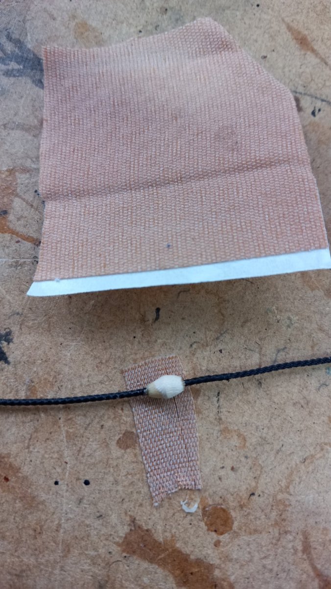
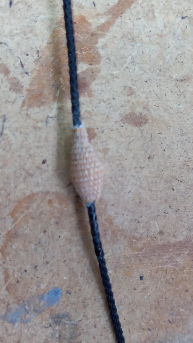
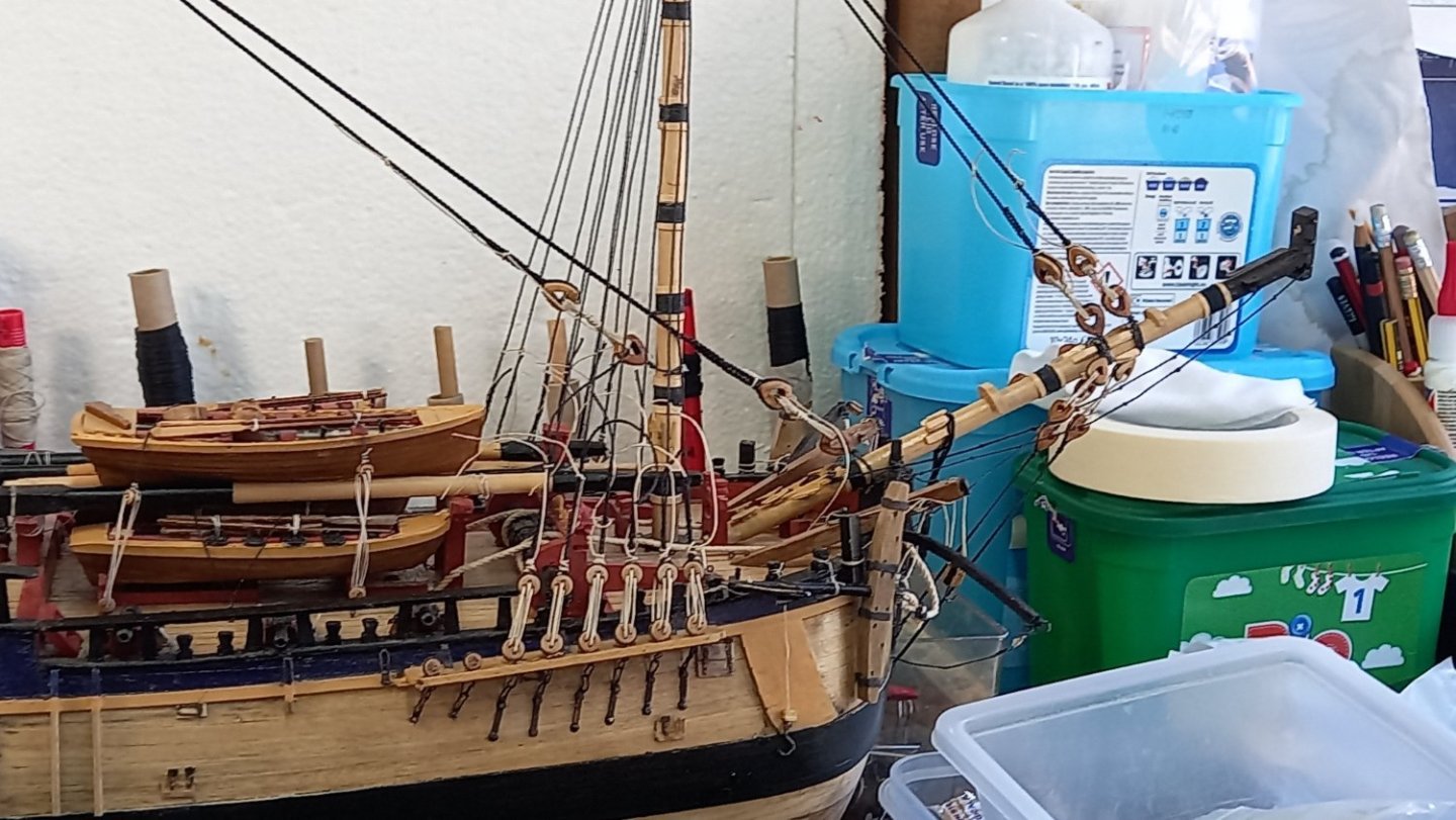
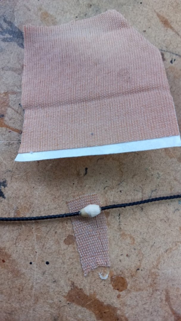
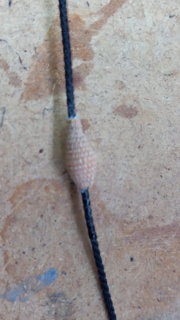
I made a a start on the lower stays and preventer stays.I attempted to make the mouse using fabric sticking plaster over small wood bobbin pieces turned on a lathe.I then blacked these using Indian ink to ensure the pattern remaind I thought these turned out reasonably well but slightly on the large side. I also used thread supplied by Ropes of scale to get the correct size threads for 1:64 scale and sizes were taken from Lees book 'The masting and rigging of english ships of war' Next up will be the top mast and their stays and shrouds. Once these are properly adjusted and the masts are in their correct positions, the long task of fitting their ratlines. Which is something I am not particularly looking forward to. Almost forgot the futtock shrouds so still got a long way to go.
-
Thank you mark and again thank you for keeping me right. Your input is always appreciated. I would also like to thank David for using his photograph and other modellers who have helped me how to understand the rabbet and bearded line works on this model.What a great forum this has been for me personally.Best regards Dave
-
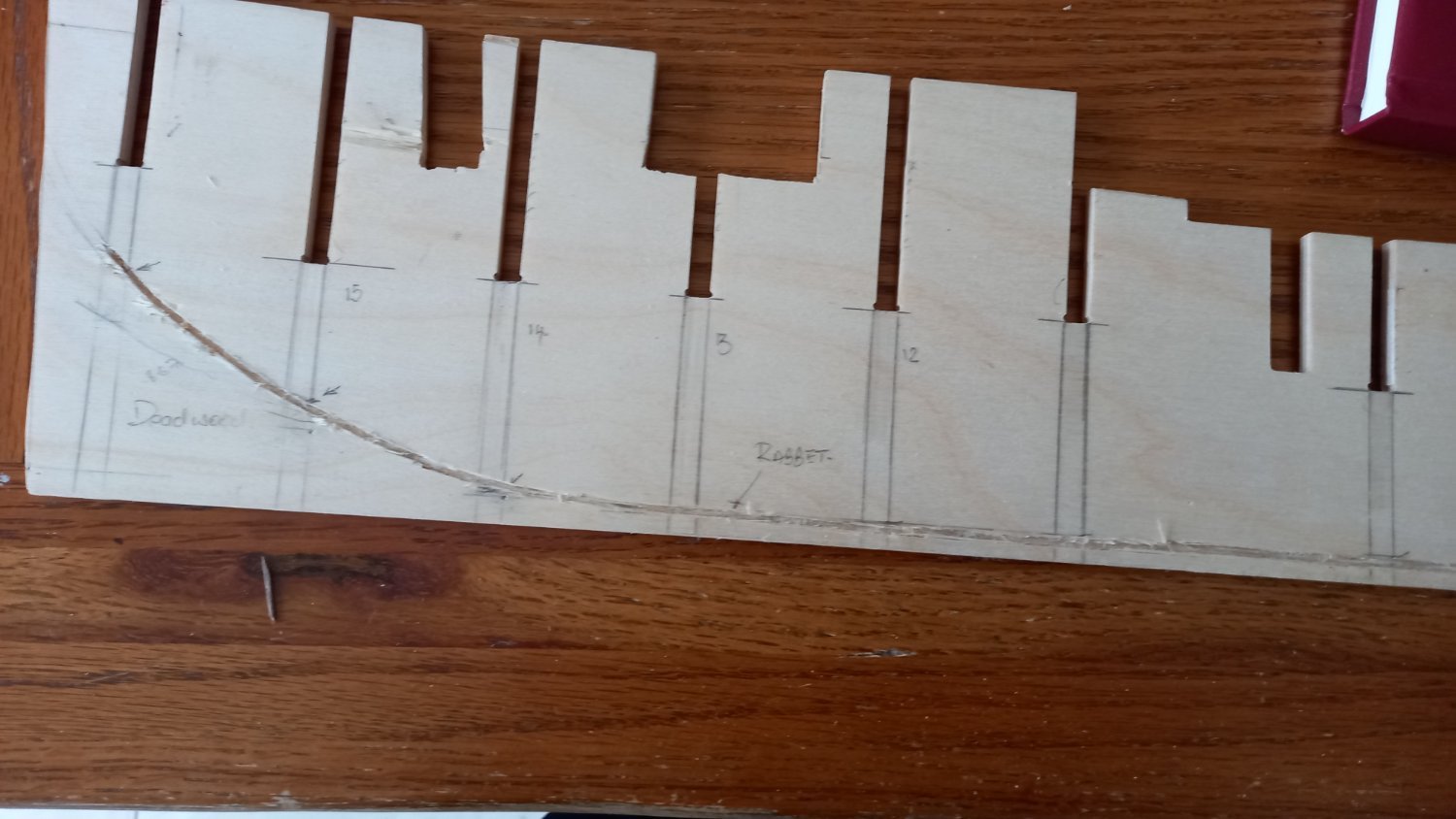
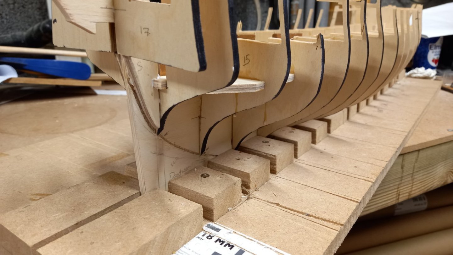
Thank you No Idea for you input and welcome aboard. I could be wrong and this is my first effort at contructing a rabbet but I thought that the rabbet would follow the line of the two pieces of wood supplied in the kit which gives additional support for the first planking. This I believe is also the bearded line I used these pieces to mark where the rabbet would go. I still need to work out how much material I need to remove (deadwood area ) and I might have to adjust this somewhat depending upon how the first layer of planks lie..Hopfully it will turn out like this. There was no seperate stern post on this kit so I removed a section of the plywood and need to make one as per AOTS Diana.At the top edge of the rabbet is about 1 mm from where the stern post will be and works out is the thickness of the second planking. Hope I am making sense. Best regards Dave
-
Good to know so will do some tests . It might even turn out to be the alcohol I mixed with the shellac, who knows! Thanks once again for your early response.
-
Thank you David I have ordered those pens and see how they react with the shellac. The pens I work with at the moment have been ok with walnut so not sure if it is the wood or the shelac that is causing them to bleed. Just as a matter of interest David, what are you using to seal your wood with?
-
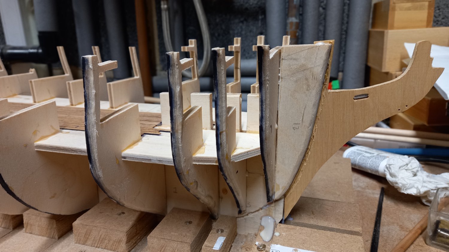
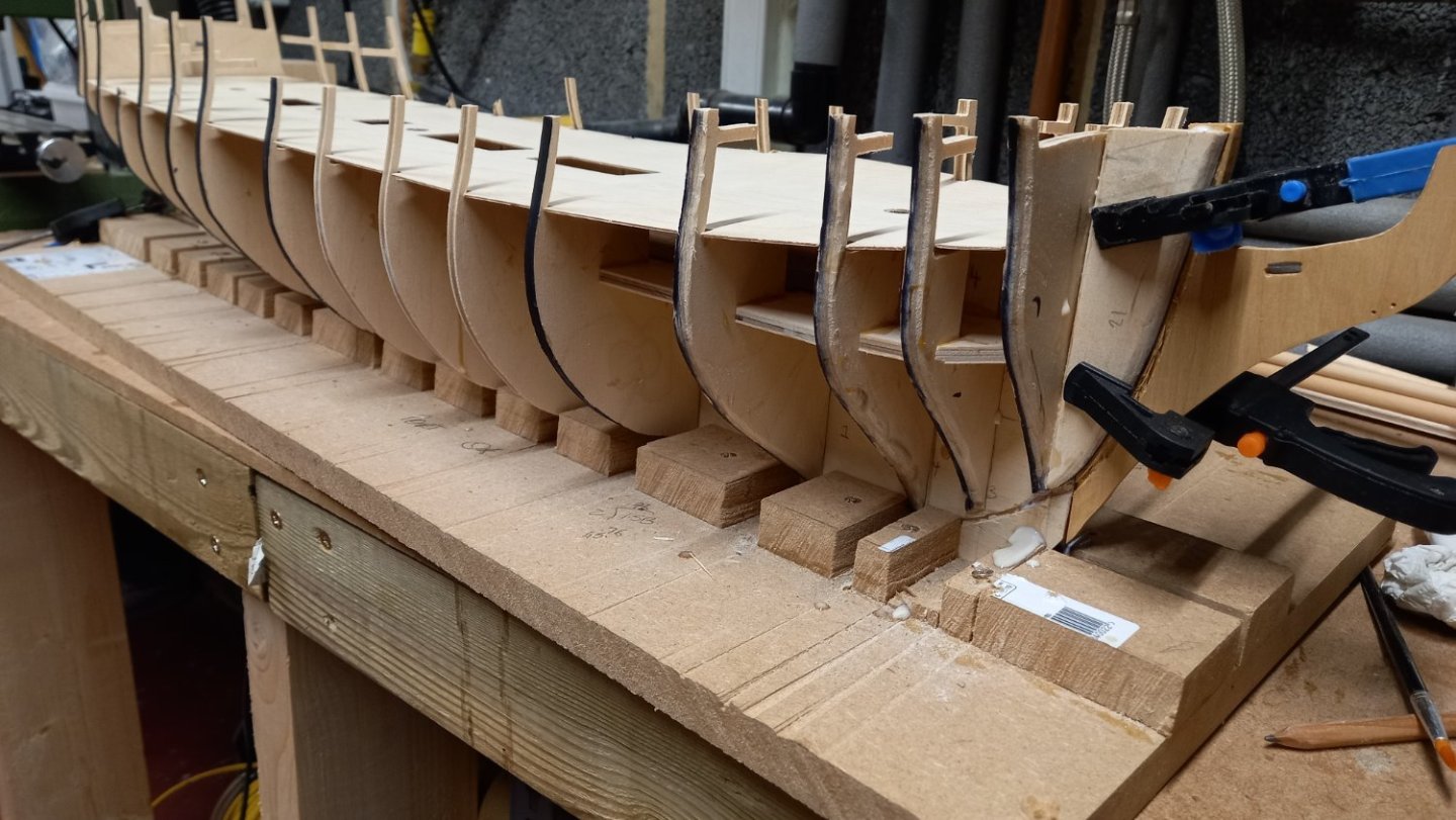
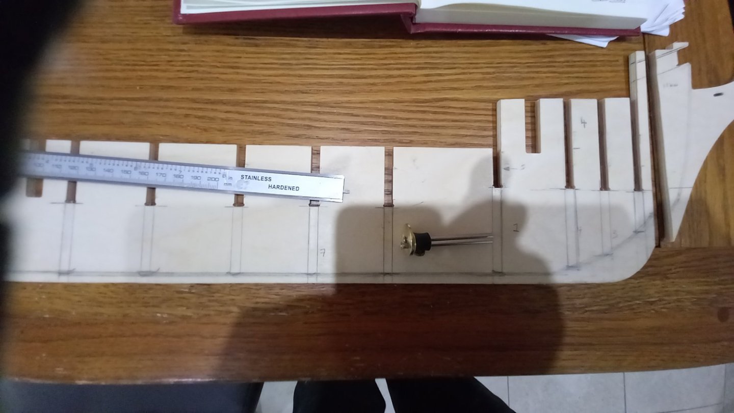
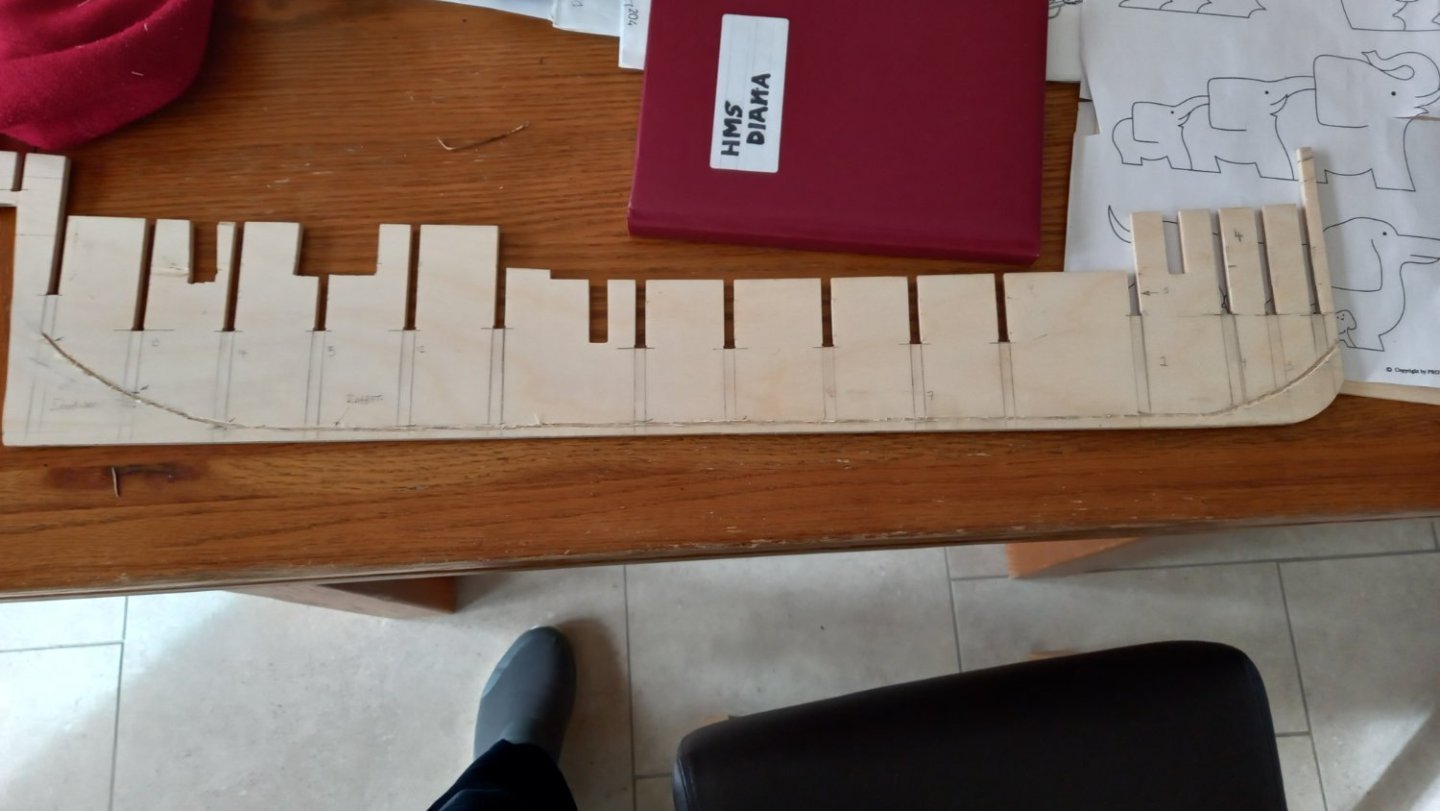
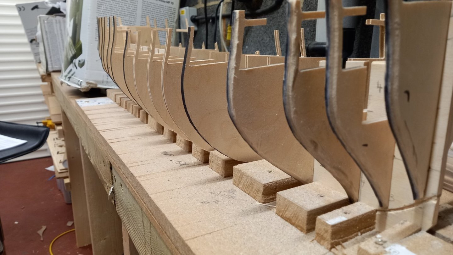
Finally recieved the Boxwood from Timberline and made the stem/cutwater, using the origonal as a template to ensure the correct size. I also notice even whilst the false keel was sitting tightly in the base and the bottom false deck was in position it was necessary to move the front section of the keel, so that the centre line up with the first bulkhead. photo here of the bulkhead glued ito the correct position which has ensured that the stem lines up properly continued the rabbet onto the stem and stern using parts 20 21 and 22 as guides for the shape of the rabbet. I then used my milling machine to machine a 1 mm slot for the bowsprit gammon lashing and two holes for the bobstays, again using the origonal stem as a template. I then proceeded to glue all the bulkheads and stem and the above stem and stern supports into position . I am now fairly happy that the keel is straight and once the next deck is secured into position then it should be safe to remove the workpiece from the base and frame and I am thinking about what is next. Which is how to drill a 10 mm hole for the bowsprit and to ensure I get the correct angle. The feint lines you can see in one of the photos is the same angle as shown on the AOTS Diana. I have already checked that this clears the figure head.

-
Jason I am more than happy to hear your comments as two or more heads is better than one. At the moment CMB do not have any maple strips in of any size other than the 1 mm x 100mm sheets hence the comments regards making my own. There are 60 mtrs of 1 x 4 mm tanganyka strips in the kit, so I think that could take me some time to cut into strips and this is something I have never tried so unsure how much wastage on top of that. I might gave CMB a call and see if they intend to get any more maple in the near future or perhaps they are having problems sourcing it too. I already have some walnut in stock but would just need a bit more to do the job, so depending upon CMB replies I might end up going down that route. I do like the sound of using maple as it seems very popular for decking. Thank you once again Jason for your help and patience. Best regards Dave.
-
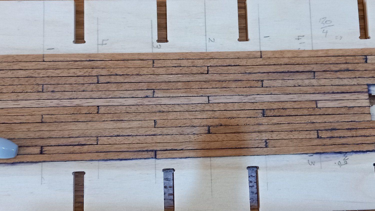
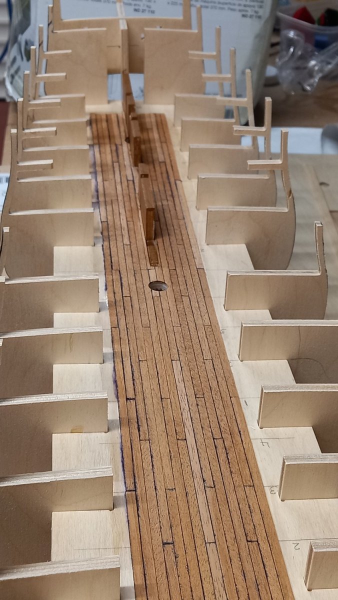
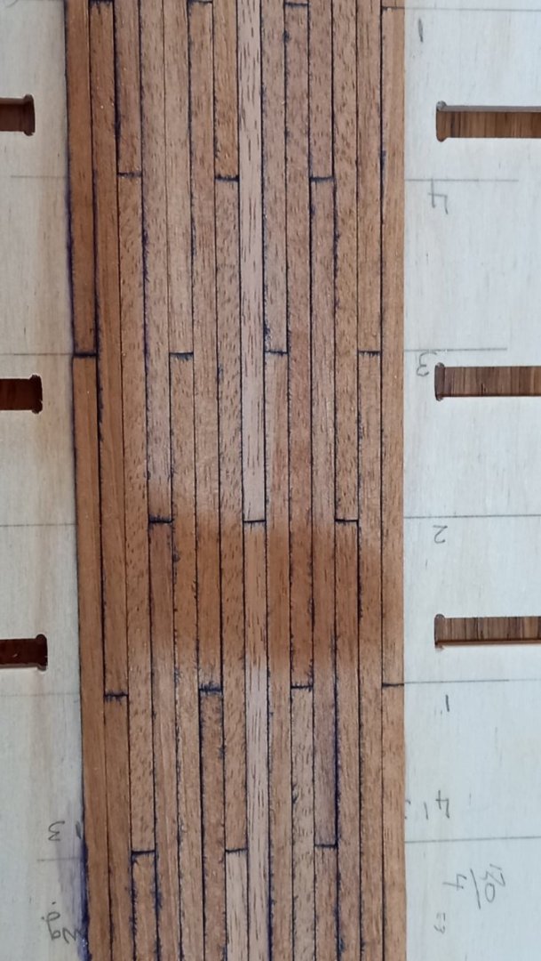
The supplied Maple strips for the Deck turns out to be Tanganyka and not maple as listed which I have not used before so thought I would give it a try on the lower deck which will mostly not be seen. This turned out to not be a great success. Firstly I used permanent marker for staining the edges of the tanganyka strips which worked great on Walnut for simulating calking between the planks . I then used 2 parts shelac 1 part alcohol to seal the wood . Unfortunately not only has the ink leached into the grain but I am not sure I like the fleck in the grain of the tanganyka to start with which is totally out of scale too. Here are a couple of photos of the mess. Conclusion. First off get rid of the Tanganyka . Second try and source some 1mm x 4 mm Maple strips. Not so easy when ready made here in the uk. I have never used maple before but looking at samples of local suppliers the grain looks to be too large for 1:64 however a few modellers have used this in the past . Alternatively I could easily source some 1mm thick x 100mm wide sheets and cut them myself on a Proxxon FET saw but I think there could be a lot of waste Then there is the other problem of using either the permenant marker and shellac together or perhaps its the mixing with alcohol. Perhaps I should return to using sand and sealer instead of shellac or try something else to simulate the calking. I am inclined to go back to what has for me been tried and tested and use walnut for the decking which is readily available and always looks good when sand and sealer is used in combination with the permenant marker. I have also used charcoal or pencil lead but do not think it makes as good a job as the marker pen. No doubt I will need to carry out more tests before on the decking before I finally decide which is the best coarse of action.


-
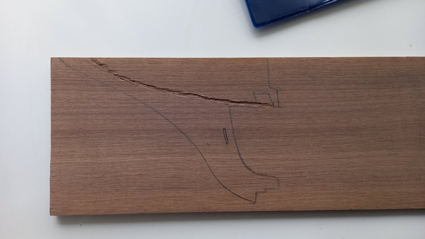
I have made a start on the rabbet, at least on the keel but not on the stem as I am still waiting for my Boxwood to arrive. I found the rabbet quite difficult and ended up with the rabbet wider than what was required, due to the chisel following the grain and lifting the edges of the plywood keel. Hopefully it won't matter too much when finished. I marked the rabbet using a Veritas marking wheel which I use for marking my masts from square stock. \i found working on walnut easier to cut the rabbet and keep within the markings. I am not sure how far to take the rabbet to the stern post as I will be taking off some off the material for the deadwood area. I will probably leave the stern post off until I have finished both 1st and 2nd planking and cut a straight edge I think.. I have also made a start on rounding of the edges a bit so as to give the first planking more area to glue. Before doing so I blacked the edge with permanent marker so that I wouldn,t remove too much material. I can finalize this better once the bulheads are glued into position

-
Nice work on those Vanguard kits . Far supperior than Caldercraft. Lokking forward to seeing how they turn out. Regards the paint. Good tip regarding diluting the Admiraltty acrylics. I have just got myself an airbrush system and have already tried diluting the red orche and the differnce is amazing., however no better than what you have produced.
- 310 replies
-
- 2
-

-
- Diana
- Caldercraft
- (and 1 more)
-
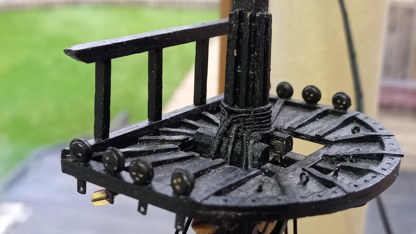
I have just noticed what great paint work that you do Daviid and wonder if you achieve such results using an airbrush or hand painted? Also I like the finish of some of the black as it has a slight sheen to it. Are you using a varnish over the top of the black paint and wonder if you are using a different finish than Caldercrafts own dull black acrylic? Sorry for all the questions on your log but your masts and tops are very impressive. Best regards dave
-
Excellent Choice Sam. I have been thinking of going down the Vanguard route sometime in the future. There are some great builds on here of the Sphinx and other models by Vanguard. I will look forward to following her when you get started.
-
Fantastic Looking Endeavour Sam and you are obviously a very comitted working as you will soon be a head of me .At this rate you will soon be thinking of your next project. Any thoughts on what you would like to do?
-
I would just like to add a side note regarding sourcing boxwood for Stem/cutwater and stern post and as I am also looking for 11mm thick boxwood for the masts I decided to give Timberline a call . They have been kind enough to cut the 5mm thickness from their origonal 6mm stock without any extra costs due to buying from them before. So hope it is ok to add this thank you to my build log. I think I have pretty much all I need now to proceed. I just need to find the time away from the Endeavour rigging which I am finding very time consuming. However I suppose that is what the hobby is all about.
-
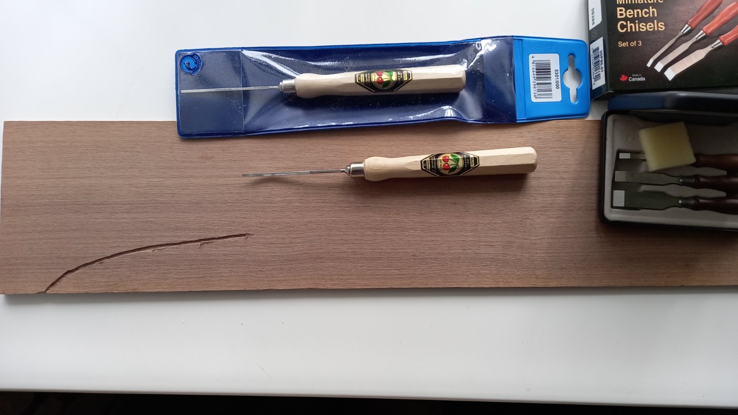
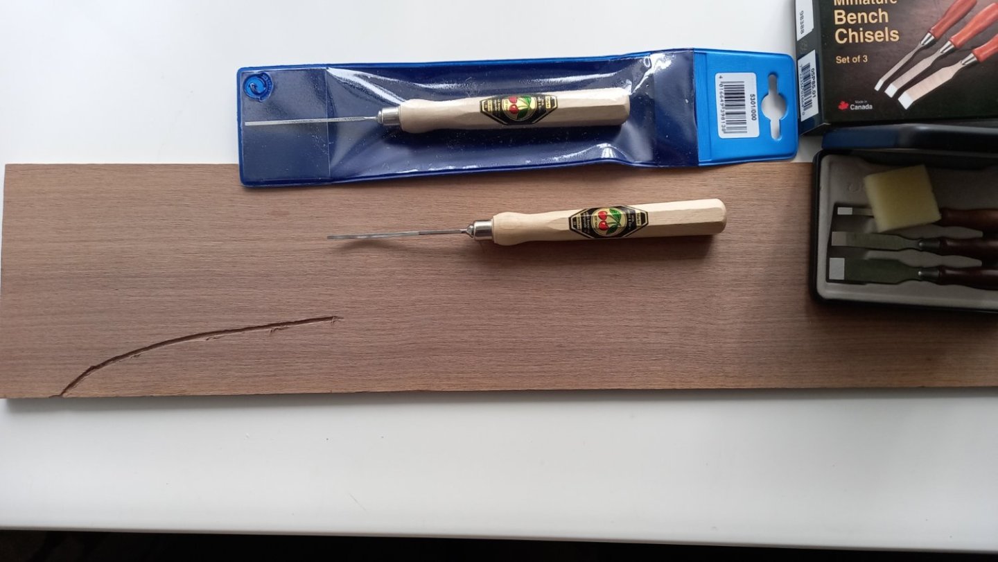
Thank you David for your input. The chisels are made by Kirschen but I only bought 2 of these which are 1.5mm wide there are a few more of these but are sold seperately. The 3 chisel set in a box are made by Veritas which has a very good name. Both types were bought from Axminister tools here in the UK. https://www.axminstertools.com/hand-tools/chisels
-
Continuing the shrouds with only the Mizzen of the lower shrouds to do. Then onto the lower stays and back stays.

-
Bought some Tools, mainly chisels for an attempt at cutting a rabbet with variable angles/ shapes. Alaso some practice on walnut sheet and hopefully I got the hang of using these very sharp chisels. I am a little concerned regarding the thickness of the walnut as it is 0.25mm undersize of the 5mm thickness of the false keel plywood and I am wondering if this will cause a problem down the line . Unfortunately I do not have any 5 mm boxwood in stock so thought I would see if Timberline https://shop.exotichardwoods.co.uk/ can supply me with some together with 11mm for the masts as I haven't got any of this either.
-
Endeavour . Back stays and Running Breast backstays
DaveBaxt replied to DaveBaxt's topic in Masting, rigging and sails
Thank you Mark and you have made some very good points and worthy of consideration. For the record, I was under the impression that the Caldercraft kit is deemed by a number of modellers as one of the better kits in terms of the accuracy of the rigging but I am not sure if this is true. Caldercraft calls them Breast back stays which Lees states were not fitted on English ships. Running Back stays I believe are something different. It would also be interesting if the AOTS Endeavour has running back stays fitted. Its altogether confusing. -
Using a serving Machine. ( Syren Serv o matic)
DaveBaxt replied to DaveBaxt's topic in Masting, rigging and sails
I would just like to add that I have sorted out this problem and it was nothing to do with the machine. I have been allowing too much line between my hand and the bobbin of thread and allowing it to twist into loops and eventually getting into a tangle. I have since mastered how to use it and quite pleased with the results. keeping the length of line fairly short prevents the above happening so happy days. I just thought I would let Chuck know this. Thank you . Best regards Dave -
Endeavour . Back stays and Running Breast backstays
DaveBaxt replied to DaveBaxt's topic in Masting, rigging and sails
Just came across this thread and thanks to Blue Ensign who staes that Lees is actually differentiating between Breast Back stays and Running breast backstays so perhaps the latter were carried on the Endeavour afterall. -
Endeavour . Back stays and Running Breast backstays
DaveBaxt replied to DaveBaxt's topic in Masting, rigging and sails
Yes I agree Allan so will probably go down the Lees route so will probably end up missing them out. A shame really as the recesses for the dead eye chain plates have allowed for these so now there is a gap in the shrouds. Oh well I live and learn and next time I will work all this out before I fit the channels. Thank you once again for your early response. Best regards Dave -
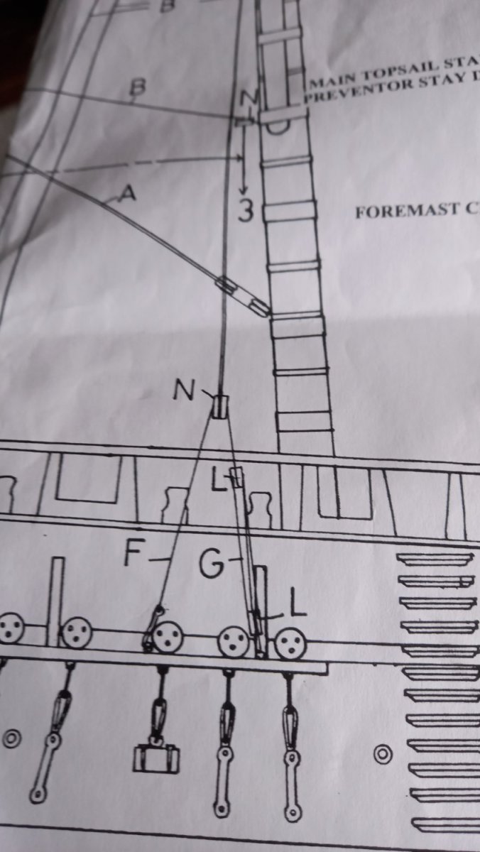
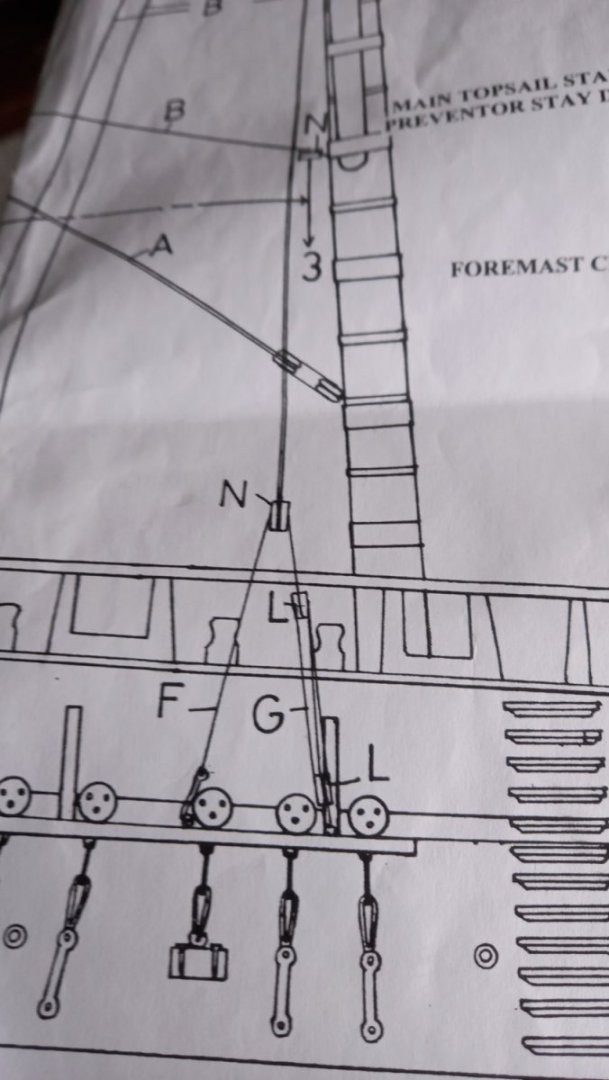
According to Caldercraft drawings there are two standing back stays on both the fore and main top masts and topgallant masts and the channels have two small dead eyes port and stbd for these. However according to the Royal museum at Greenwich ( via wiki) there is only one dead eye on each channel for backstays. some modellers have had the forsight to fit as such. The Caldercraft drawings also shows Running Breast Backstays on both Fore and main top masts. However Lees Book ' The Mast and Rigging of ships of war' states that Breast Back stays are usually not fitted on English ships. Can I therefore assume that Running Breast Back stays are also not fitted. I am finding this a bit confusing to say the least and perhaps someone can shine a bit of light on this , I wonder what configuration Steel has or AOTS Endeavor out of interest. Thank you Bwst regards Dave
-
Cheers for that Allan. Good point regards the size of knots might look too big but will see what it looks like on the model. Thank you again for your help.best regards Dave
.jpg.8f331b703ff0d3378a5bd7471f6b2b44.jpg)