DONATION DRIVE - SUPPORT MSW - DO YOUR PART TO KEEP THIS GREAT FORUM GOING! (91 donations so far out of 49,000 members - C'mon guys!)
×


Gabek
-
Posts
310 -
Joined
-
Last visited
Content Type
Profiles
Forums
Gallery
Events
Everything posted by Gabek
-

Pandora by marsalv - FINISHED - 1:52
Gabek replied to marsalv's topic in - Build logs for subjects built 1751 - 1800
Great work, mate! Looking forward to watching this beautiful model come together. Clear skies, Gabe -
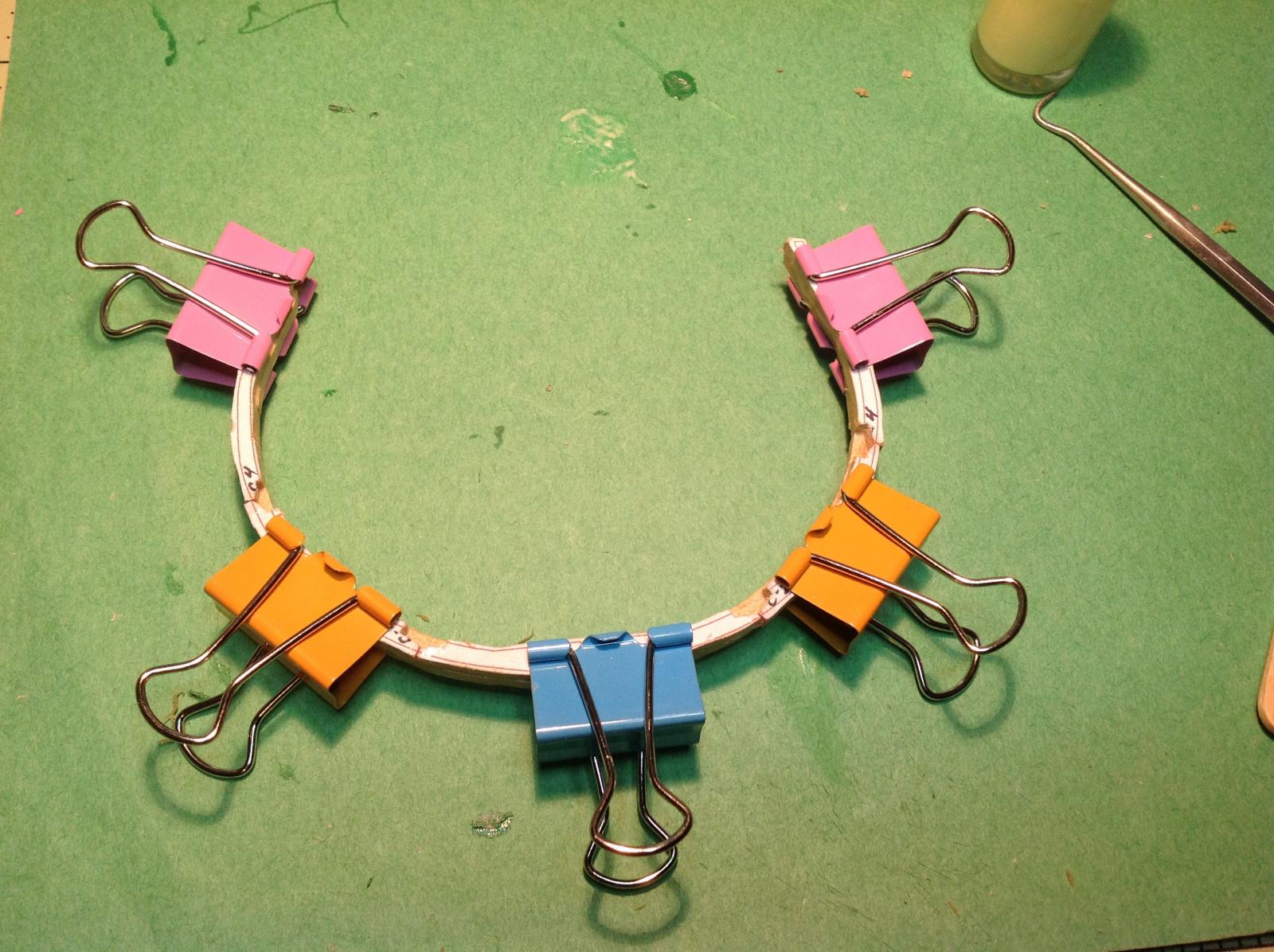
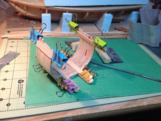
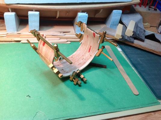
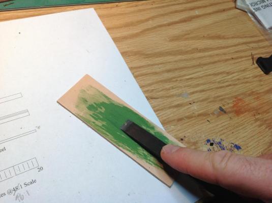
Fairing the frames I've been thinking about how I was going to manage to fair frames that are as slender as these are. Being so flexible, my worry was that I couldn't keep them in position in a jig. I tried clamping them all together and found that they were quite rigid and could resist being moved around quite well. I decided to fair them bundled together like. At this scale, I didn't think that the shape of the hull would be drastically affected by removing the space between midship square frames at this scale. At first I used popsicle sticks and binder clips as clamping cauls. These were a bit cumbersome to work around and staring at me from my pegboard were my beautiful little brass bar clamps. I taped card stock to the jaws to prevent maring the wood and switch over these. Shaped sanding blocks worked well for the outside surfaces (I chuckle thinking of putting this over my knee like Ray did!) but there wasn't much room to work inside. I was about to make a sanding stick, like Ray did, and then thought of my files. Believe it or not, I ended up using a chainsaw file to fair the inside of my frames! First clamping method Eventual clamping method.
-
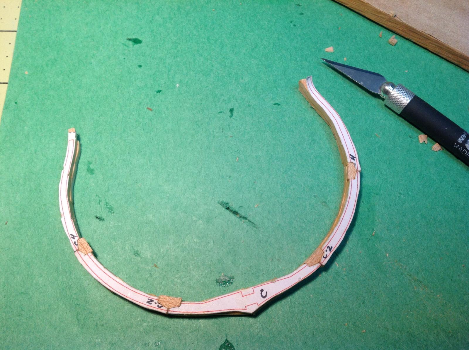
Thank you, Nils! I am quite flattered for your acknowledgement and may I bow to you for your museum pieces! Frame Bend 5 I noticed in the Triton plans that forward of the midship frame the floor futtocks face forward, and aft of the midship frame the floor futtock face aft. I decided to reverse frame 5 from the plans so I could show the different futtock arrangement and work on making a cross chock and some scarf joints. (I don't feel bad about this because some references support this arrangement). I had already prepared the third and fifth futtocks according to plan before deciding to add chocks, etc, but to make the scarfs I had to cut out new pieces that were longer to allow the overlap at the joint. I thought that I would cut out a single piece of the two futtocks together, cut the scarf and pick which futtock came out better. The cutting was much easier than I had anticipated, the knife I used sharp and the scarfs came out very clean. And now, my model-making colleagues, I have to confess that I cheated. I just put the two pieces back together in my build! Glued up Cleaned up


-
Thanks, Ray. I suppose for my build...I should dream small? (I know that I'm thinking about this model so much that I'm starting to see it in my dreams!) Regards, Gabe
-
Thanks for the comment, Ray. Many of the things I've been thinking of doing for this build I see in your impressive and incredibly quickly-built Triton! I even contemplated extending the model to include the mast, like you did...but I decided to go simple for my first scratch build. Looking at the AotS Pandora book I saw how the cross-section diagrams showed the outlines of the boats on the skids. In the back of my mind I thought it would be interesting to add them to my Triton and I could envision the cross section of the boats..and I see that you did it! Very, very cool. You have also given me a whole lot of new ideas I hope I can manage at this scale. Regards, Gabe PS. Give my regards to Woody!
-
I love this book, as well, but I'm not entirely happy that there is no index or at least a list of the model SLRs.
-
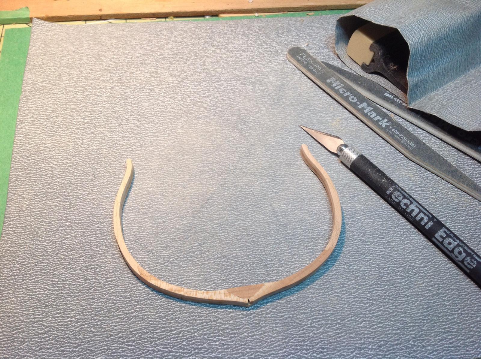
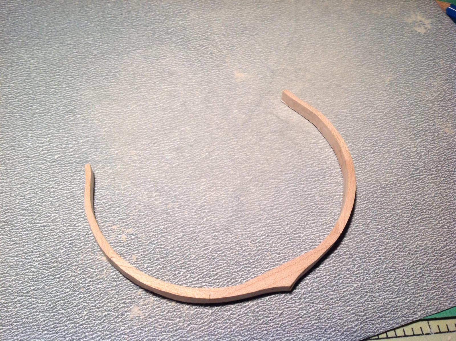
Thanks, Matrim. I think I may have made that mistake on the other frames, but they really are so weak that I can see them breaking when I try to fair them later. I think I may make the planking a bit thicker and fair up the lines by sanding them, instead. These outside, built-up frames however are much stronger (my hat goes off to the ship designers and builders of yore!) And, like a kid, I couldn't wait to see what the frame would look like so I sanded it up and the chocks are almost invisible (just the way I like it!). A couple of the butt joints between the futtocks, however, are not tight...something I have to work on for frame pair 5. (Hmmm...uploader said the picture file was too big...but it's only 715 kB. I posted the topic and hit edit, now it works. Anyone else getting this?)
-
Well, thought I'd just check the glue and found it was dry. So, I decided to try adding chocks...it took maybe 30 minutes, if that! Tough to get a perfect fit, but I think it will do. I also noticed just how much stronger this frame is compared to the one-piece frames I've already made. Using the grain of the wood properly sure helps! Sanding the frame to size is next.

-
HMS Beagle by maurino - Mamoli
Gabek replied to maurino's topic in - Kit build logs for subjects built from 1801 - 1850
Hello Mauro, Looking forward to seeing your work on this model. This is a kit that is on my bucket list! Best wishes and clear skies! Gabe -
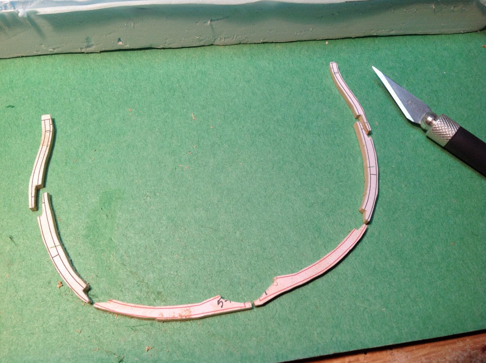
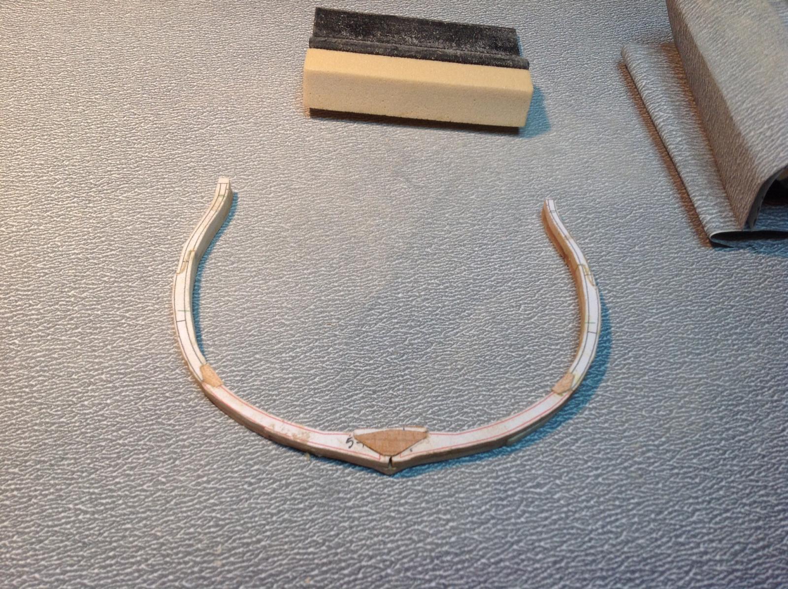
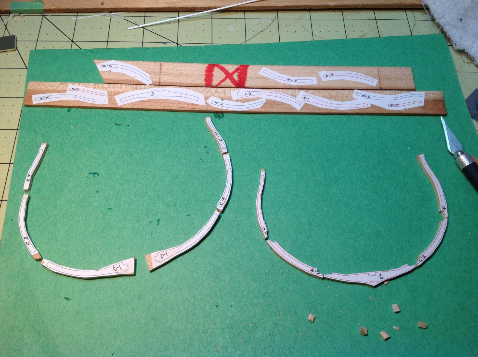
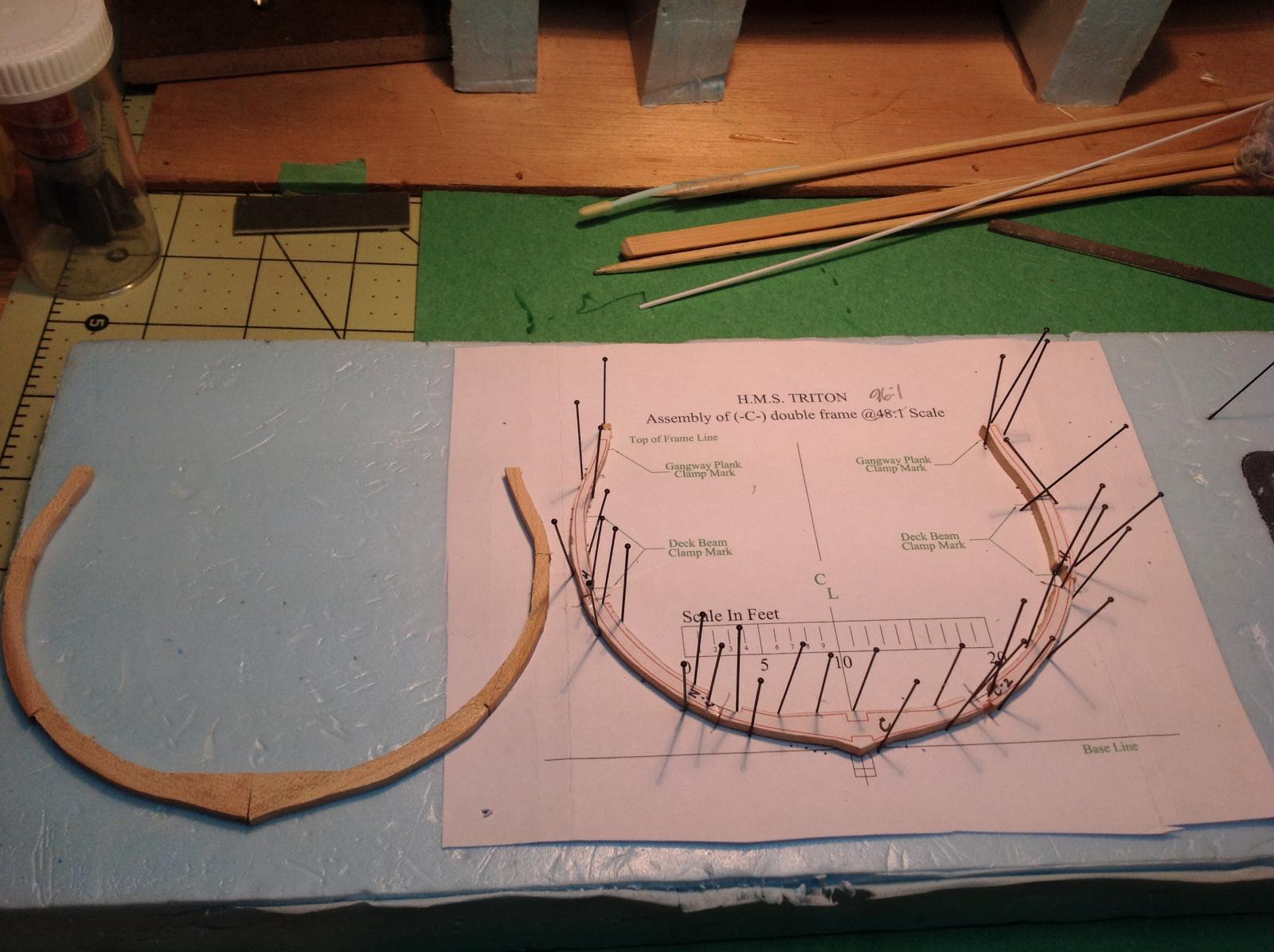
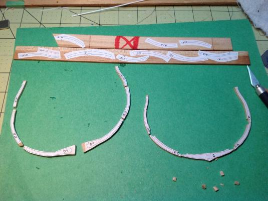
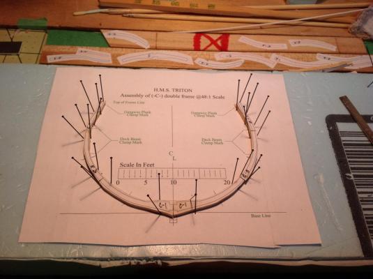
Ah...summer holidays. Done another term of teaching and managed to finish a ship in a bottle as a gift for my dad while my parents were in town to celebrate my youngest son's graduation from high school. I can now pick up the Triton where I left off. I had already prepped some 3/16" cherry for the two frame pairs (C and 5) that I was going to build up. I glued the futtock patterns along the grain and roughly cut them out on the scroll saw. Not ever having done this before, I decided to try to complete one frame pair first before working on the other and make any necessary modifications to my method. I left extra wood on the futtocks thinking that it might be easier to clean them up once the frames were all built and stronger. Thinking of some of the things I want to do with this build I began doing some more research on frigate construction. I own the Anatomy of a Ship books on the HMS Pandora (24 gun) and the HMS Diana (36) and I soon noticed that chocks were used between most of the futtocks, particularly the lower ones, and sometimes scarfs for upper futtocks. I made a decision that I may regret later: I was going to install chocks on these built-up frames, but only on the futtocks that would be visible in the completed model. At first I thought I could just fake the chocks by scoring the frames with an x-acto knife, but I realized that the butt joint between the futtocks would bisect the simulated chocks. So, I was going to actually make chocks. The chocks in these two books look similar, but the Diana shows them being longer and more gently tapered than on the Pandora. Although I liked the look of the sleeker chocks, I decided to copy the Pandora version because the size of that frigate is closer to the Triton. Also, I thought that cutting out the futtocks at this scale might be easier with shorter chocks. I did a few measurements and calculations to come up with a plan to follow. Because I was using some really small measurements (0.7 mm in some cases) I used a knife to mark my lines on the wood. I soon discovered that cherry was fairly easy to cut so I used the knife to cut out the shapes rather than a razor saw as I had first intended. I cleaned up the notches with a needle file. Three steps in making the frames I decided to build up the frames individually and then glue the frame pairs together before installing the chocks. To build up the frames I cut the futtocks to the butt joint lines and I lined them up on a printout, using pins to hold them in place. A drop of cyano on the joints was used to hold the futtocks together until I could glue the frame pair. I carefully sanded one side of each frame on a flat surface and glued them together with carpenter's glue. I cleaned up the squeeze out where the chocks will go with a dental pick. I'll find out if this was all a mistake when I add the chocks and clean up the frames. Pinned and ready for cyano Frame pair ready Frame pair glued


-
Thanks for the comment, Donny. I have been rather occupied the last few weeks - I'm a high school teacher and June is a crazy month. However, today I started summer vacation and I hope to get back to my builds, shortly. Regards, Gabe
-
Great project, E&T, and excellent work. I've done a fair amount of reading on the north west passage expeditions and on Franklin. "Barrow's Boys" by Fleming and "Voyages of Delusion" by Williams stand out for me. I'm just amazed at the combination of bravery, determination and stupidity of these voyages. In particular, the profession of 'theoretical geography' which sent many sailors to their doom is entirely mystifying. I've started reading your blog and look forward to following your progress here on MSW. Kind regards, Gabe
- 346 replies
-
- 1
-

-
- terror
- polar exploration
- (and 2 more)
-
Thanks, Keith. Your feedback really gives me a boost everytime. Looking at my scrap bin I think I'm on my way to being an Einstein! Thanks, ziled. Looking forward to seeing your Triton. I once read that Oliver Cromwell told an artist that was painting his portrait to paint him "Warts and all". A philosophy to which I highly subscribe. There's something cathartic about putting your mistakes out there for others to see. Having a laugh over them even better! Regards, folks. Gabe
-
Welcome to the "Swifties" - there is something about the Swift that drives you crazy but you still love it! I made a point of walking away whenever I lost patience and came back to the model when I was in a good space again. Don't be afraid to change or modify the kit, that seems to be the norm...and Keith is the king of the bash! Enjoy and don't hesitate to ask questions here. I found Frank Mastini's, "Ship Modelling Simplified" a really good general resource. Regards, Gabe
- 84 replies
-
- 1
-
-
- swift
- artesania latina
- (and 1 more)
-
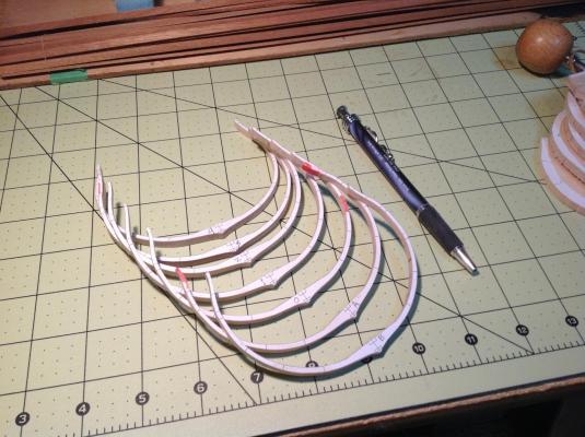
Thanks, Matrim. I have a joke I tell all my friends... Do you know what a short story is? I don't. I was a bit tired when I posted the last entry. I duplicated one photo and forgot this one of the completed frames.
-
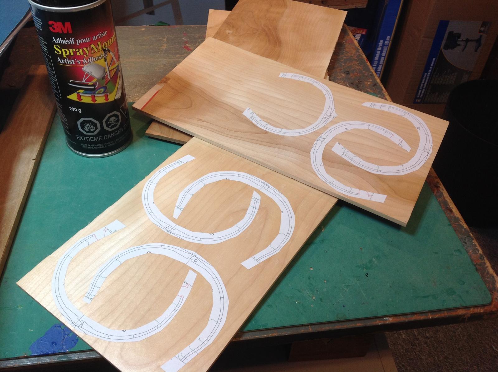
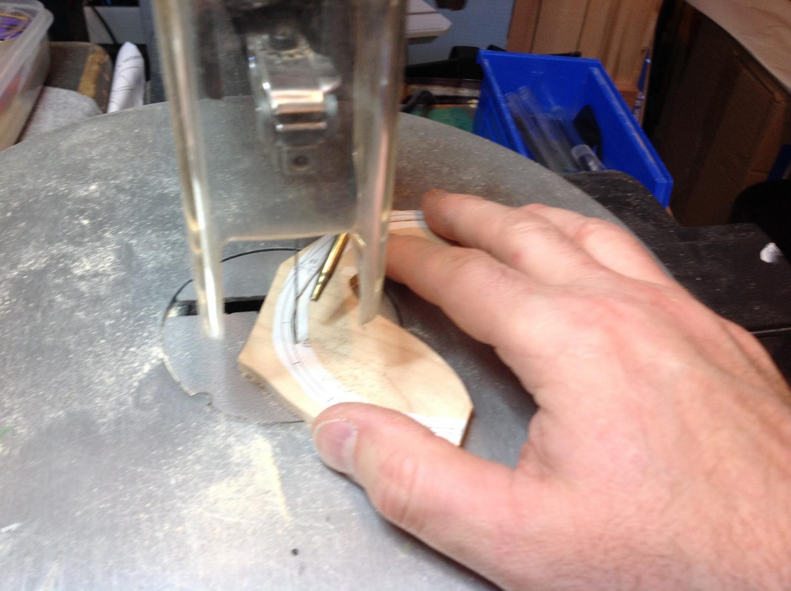
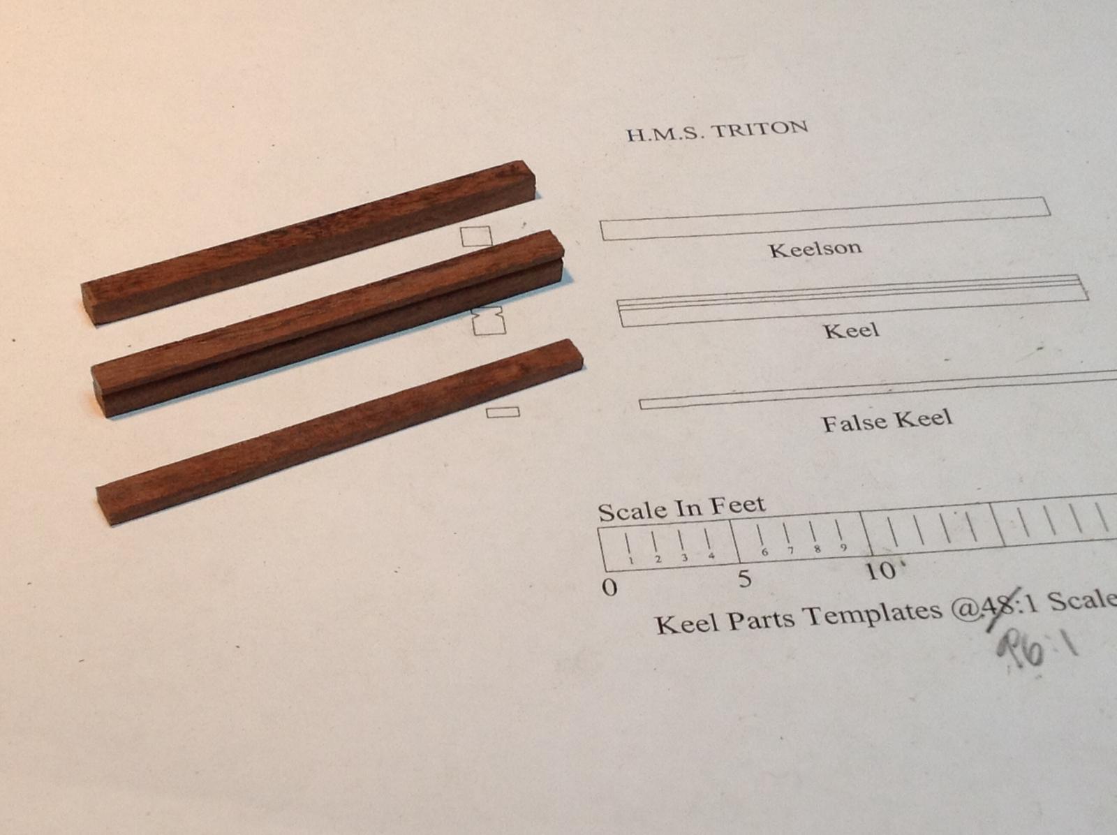
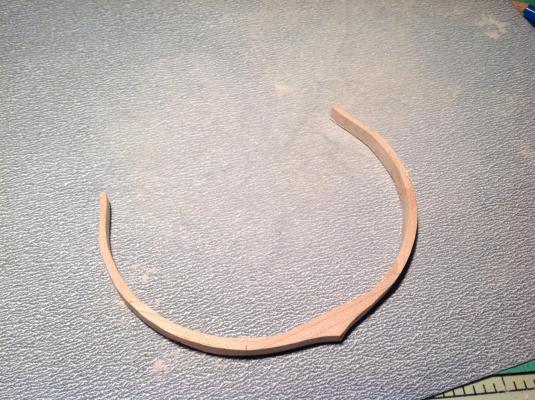
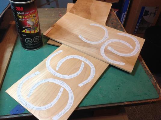
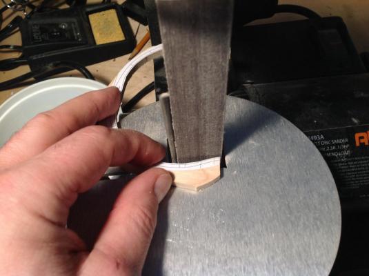
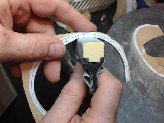
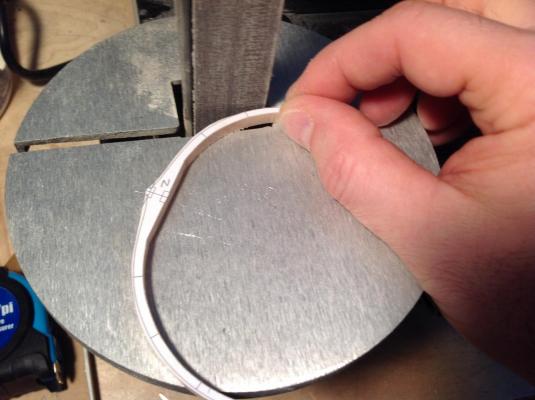
March 2014 My main motivation for starting this project was to learn the craft of scratch-building - and the online format with so many build logs and supportive modellers makes this an ideal educational environment. I also wanted to develop my skills on some of the power tools I now own, some of them thanks to my friend Clarence who was an avid woodworker but downscaled his workshop when he and his wife decided to sell their home and move into a senior's condo. His scroll saw has basically been collecting dust in my home except for the one scary time I used it to cut the rail cap on my first build, the Swift. I had no clue how to properly work it, so this project was going to be my scroll saw course. As I looked over the plans for the Triton it started to dawn on me what a challenge1/96 might be. The size of the parts for the frames would make things 'interesting' in the Chinese curse way. The futtocks would have to be cut from 3/32 stock. This was my first scratch build so I still wanted to try assembling frames, but making 9 of them at this scale was beginning to worry me. So, I came up with a compromise that I could live with...but I'm not sure what you folks might think. I plan on building the outermost frame pairs (4 and D) accordingly, but the inner frames I'm going to cut as single pieces. This way I get some experience building up frames, the model will look more authentic (outwardly at least) and I won't go nuts. After some research and a look through my supply of wood, I decided to go with birch for the inner, one-piece frame pairs. To get my 1" stock down to 3/16" it needed to be resawn and then planed...and I didn't have the equipment to get this done. However, we have a wood shop in the school where I teach and the woods teacher was happy to help me out. So, after classes on a Friday afternoon he coached and helped me make the stock I needed. (Thanks, Michael!). Later that evening I printed out the frame plans and glued them to the birch with spray adhesive. The next day I used the band saw to roughly cut apart the frames. I grabbed #4 and took it to the scroll saw for the moment of truth. I set up a fine-toothed blade, dialed in a fast speed and nervously pushed the wood into the teeth. Well, I suppose it was an ok job...but it took a bit more reading, a great YouTube video and a few more frames before I could really say I had the hang of cutting a controlled line! My goal was to use the scroll saw to get to about a millimetre of the line on the plan and then take the frame to my little belt sander to get the wood to the line. But, the frames at this scale were just so thin that I became very nervous about snapping them while getting them to size. So, I decided to cut and sand to the inside line before even cutting the outside to give at least some support to the wood as I worked on it. I chose to do the inside first because it was harder to work with at the sander. The belt sander was terrifying to use...it could remove material so fast that it took a very light touch and a lot of concentration not to grind a frame down too far. There were many heart-stopping moments, and one mistake that will need a bit of a fix. To smooth out the lines left by the sander I made a couple of sanding blocks that fit the inner and outer curves of the frames using a product called Sand-to-Shape. I had picked these up at the sale table at our Lee Valley. Eventually I had the hang of things and I was able to complete a frame in about 30 minutes. I soon realized that my one-piece frame pairs had a weakness. The upper futtocks ran with the grain of the wood, but the grain went across the first and floor futtocks. So, in addition to being very thin I had to be careful not to stress the lower parts of the frames too much. Sure enough, while cutting frame 3 on the scroll saw the blade caught the wood and it snapped. The worst part was that it happened while cutting the outside line...AFTER I had already spent the time and energy to cut and sand the inside of the frame. Ah well.


-
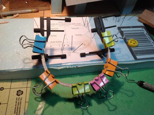
Thanks, S.C. I appreciate the comments. I can thank my father, a retired electrician, for showing me the trick of chaining cable ties like that. That d-shape they form does the trick and now that they make reusable ties it becomes practical to use them as clamps. Regards, Gabe
-
Thanks for the compliment but I'm really envious of the sails on your model, Hip...they look awesome. I really feel like my model is incomplete. Kind regards, Gabe
-
Keith has done it again! He motivated me to do something and I'm now posting my final reflection on the Swift. Inspired by one of my favourite movies, I'm going to use some headings in this post.


- 52 replies
-
- 5
-
-
- swift
- artesania latina
- (and 2 more)
-
Hey there, Cap'n! Looking forward to following your work. I've read quite a bit on Bligh and the mutiny - incredible story no matter which perspective you look at it. I've been slowly getting books, materials and building skills for making figures, as well. I've been leaning toward working with polymer clay...soft until you bake it at low temperature. If you're interested you may want to check out the book, "Creating Lifelike Figures in Polymer Clay: Tools and Techniques for Sculpting Realistic Figures". I also hope to be able to sculpt decorative work on my models using this same material. One day...one day... Kind regards, Gabe
- 625 replies
-
- 1
-
-
- bounty launch
- model shipways
- (and 1 more)
-
Thanks, folks! I've been looking at some of the other builds and, I must say, I'm a little intimidated! There is a lot of phenomenal work going on in these Triton builds and I hope I didn't bite off more than I can chew. However, I gotta start somewhere...and I know people here are great. Regards, Gabe
-
I just finished my first ship model last weekend, I've got another kit on the go, but this Triton project looks really cool and will most definitely be educational. I'm really looking forward to this. Smaller scales appeal to me for some reason. This works out well because our house is so jammed with stuff that I really don't have a lot of room to display models!

-
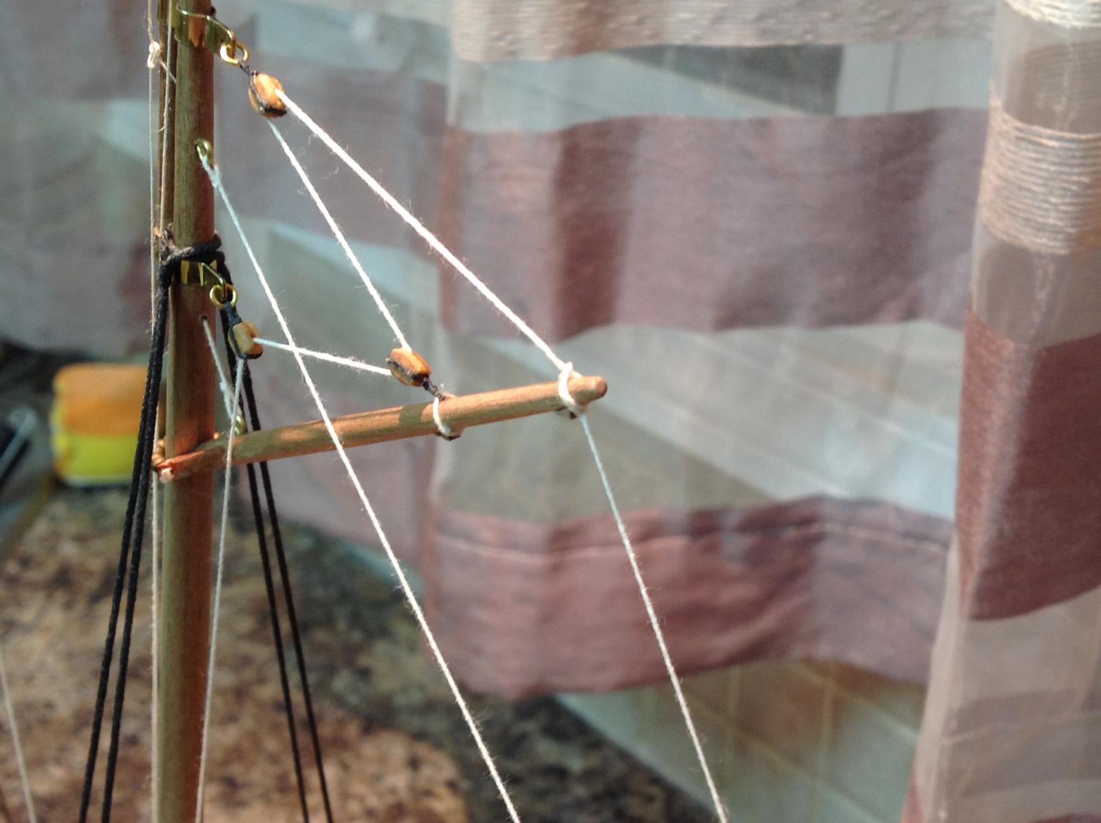
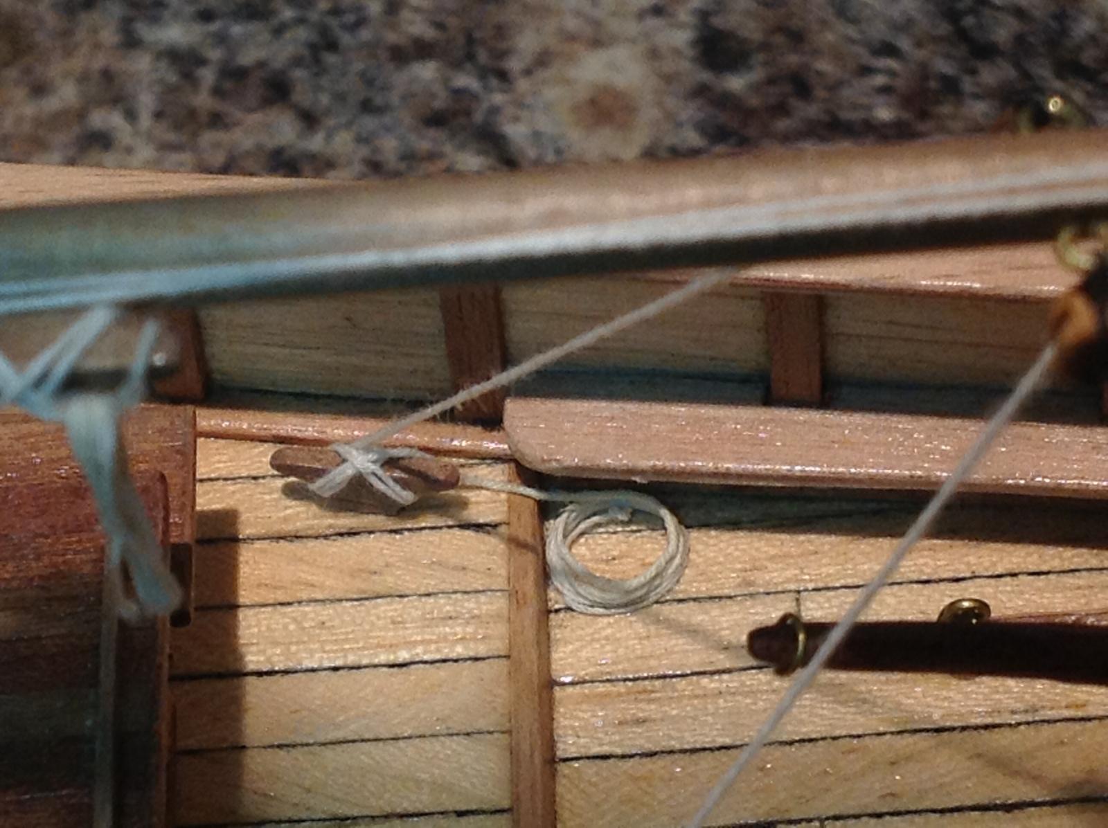
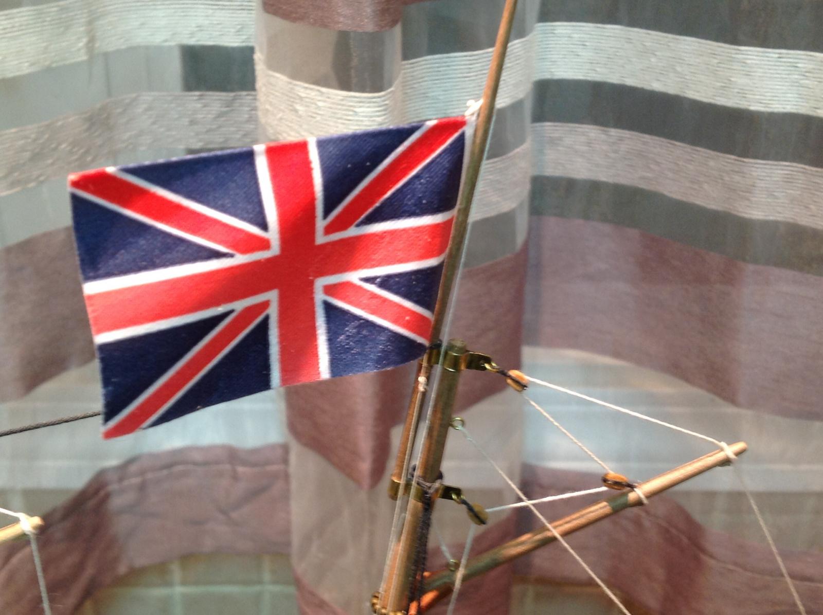
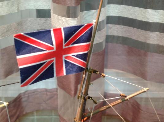
Correct hitch and advice on rigging a flag needed
Gabek replied to Gabek's topic in Masting, rigging and sails
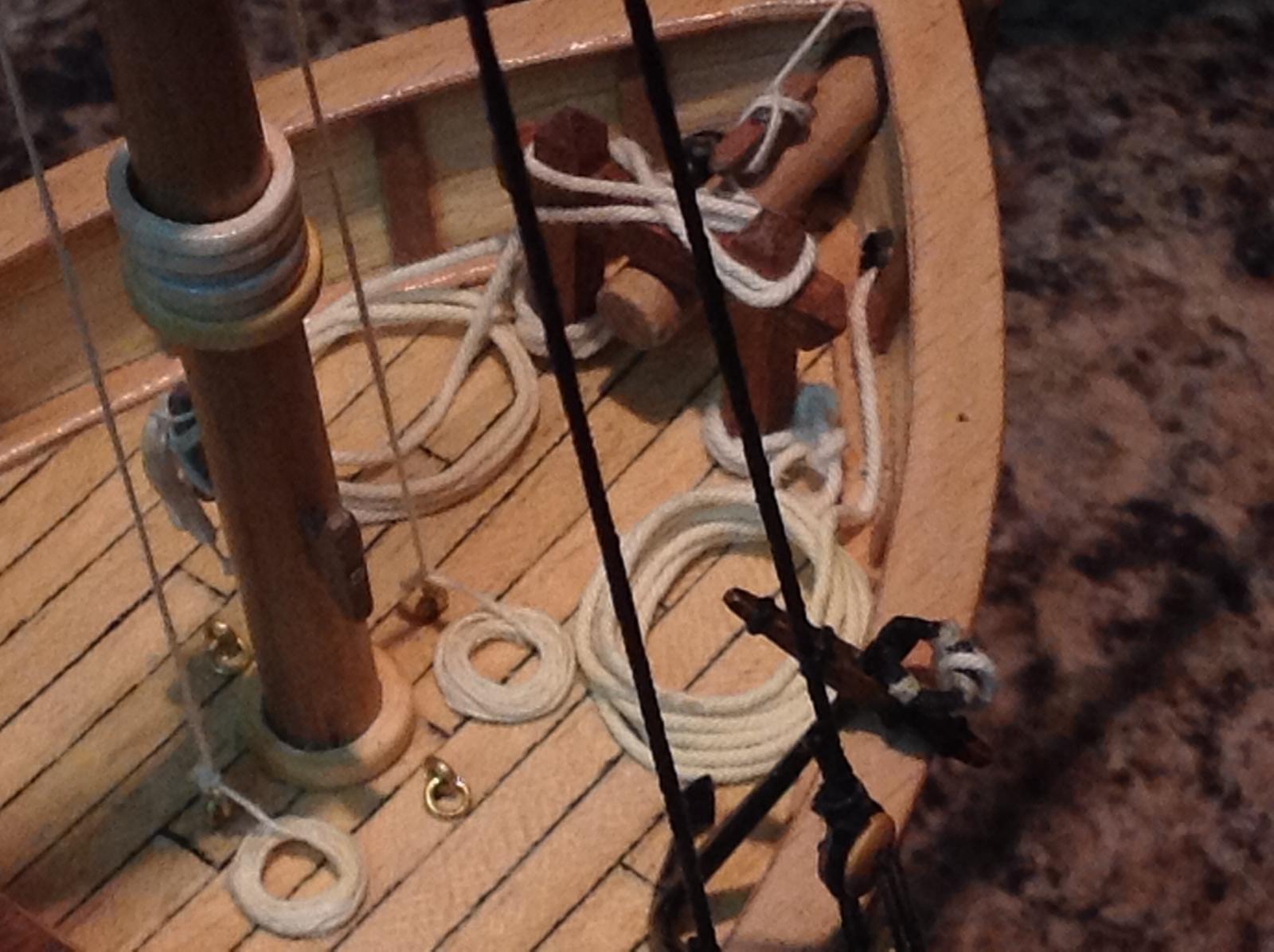
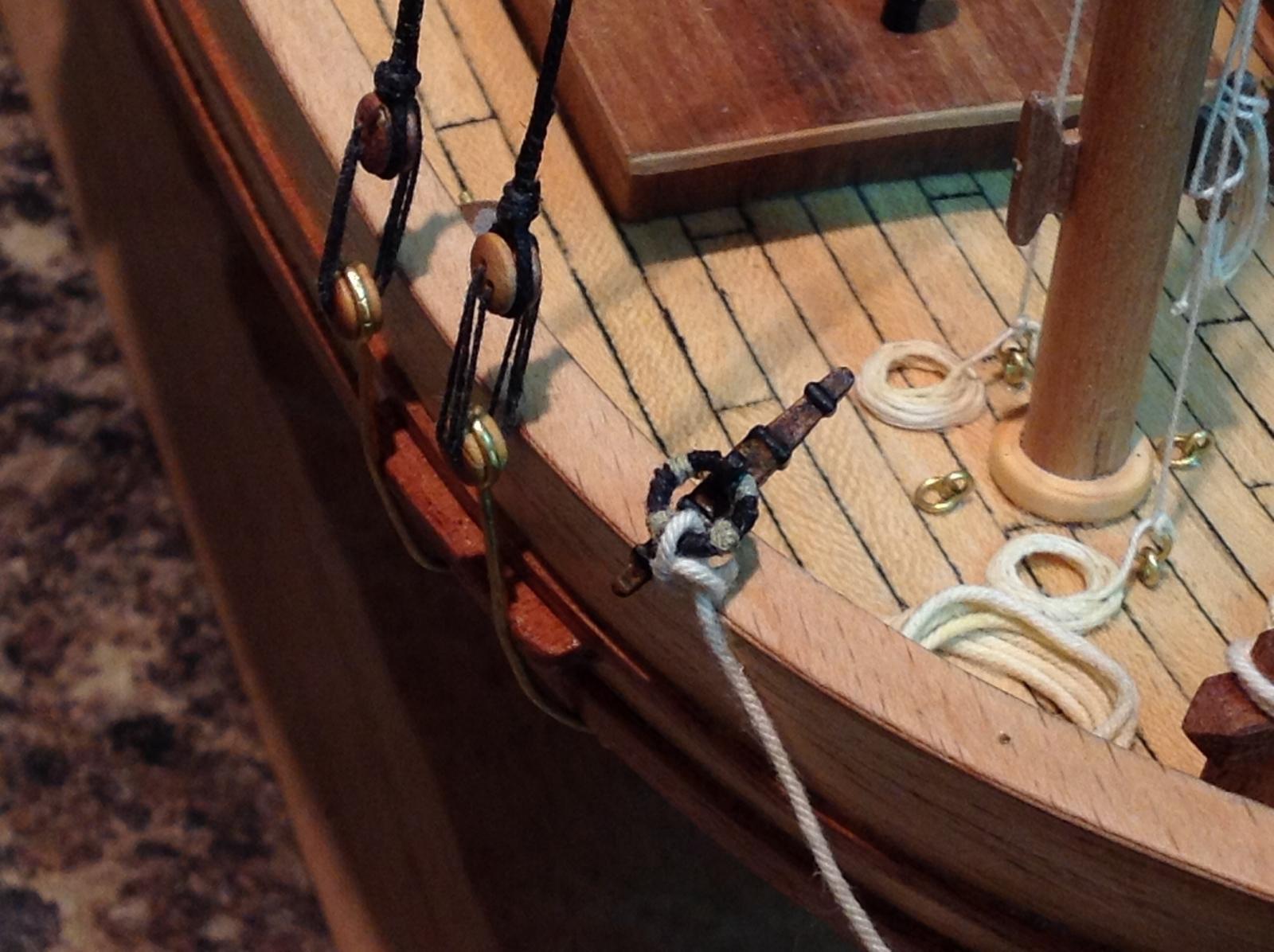
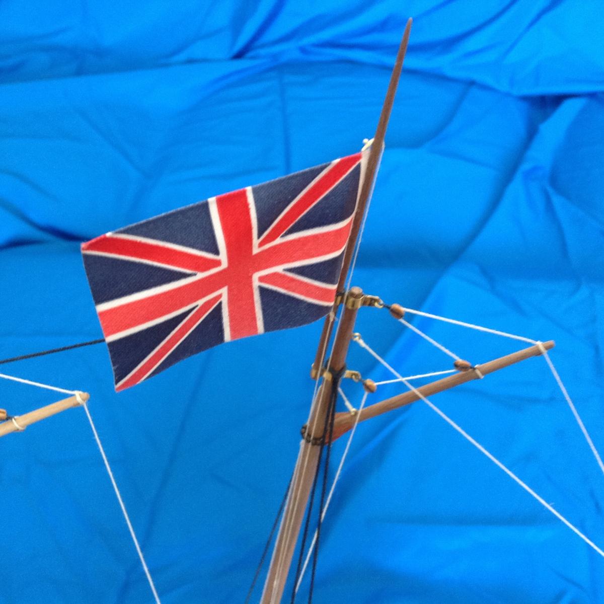
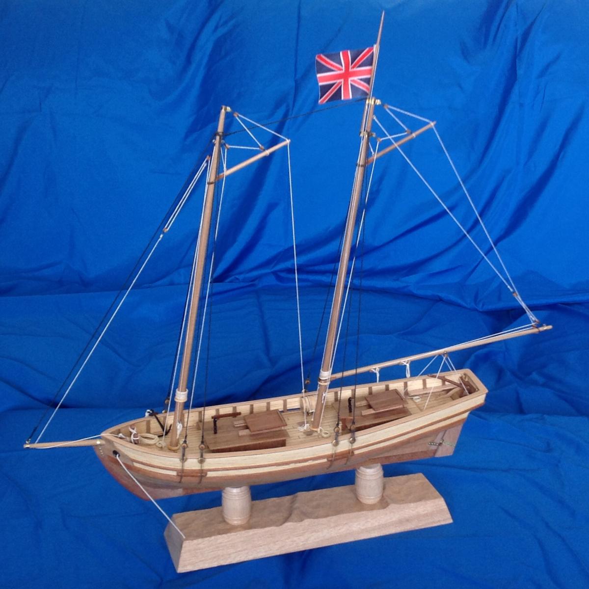
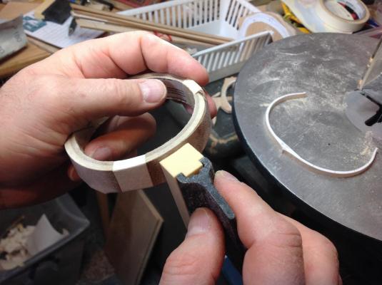
I thought I would just post the final result of everyone's advice here. Thinner line for the flag halyard. Small cleat installed on the mainmast. Toggle above the flag, eye splice below. Eye splice in the halyard for the toggle, sheet bend to attach the halyard to the eyesplice below the flag. A little extra length in the halyard to join the two ends when a flag is not being flown. And I added a few small drops of cyano to keep the flag in the direction I wanted. And my first wood model is done! Thanks a bunch, mates.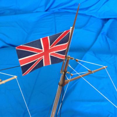

-
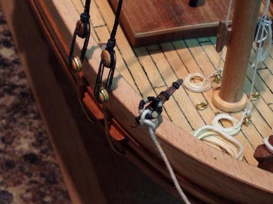
Thanks, Keith. Great to hear from you. I thought long and hard about sails. I read up on how to make furled sails and even bought some silkspan to give it a try. I also was about to bid on eBay on a "new" Swift kit with the sails just to install the sails and have a box of material. Unfortunately, the pricing went too high for my liking. In the end, I decided to go bare poles and put sails on my next kit, AL's Harvey. I've seen that Katy before! I think It was that model that convinced me not to try furled sails! I thought the fore sail looked a bit wonky. I do like that model, though. The rigging is right, for one! I'm still cursing that I didn't put blocks on the throat halyards. Kind regards, Gabe
-
Absolutely astounding work! Are all your mouldings and decorative works done on CNC? I tookup relief carving as a hobby with the goal of trying to add these kind of details to my models. (One day, but no where near as good as your work! ) Thank you for sharing this with us.