jdbondy
-
Posts
341 -
Joined
-
Last visited
Content Type
Profiles
Forums
Gallery
Events
Everything posted by jdbondy
-
 Merry Christmas, Johann! Frohliche Weihnachten! JD
 -
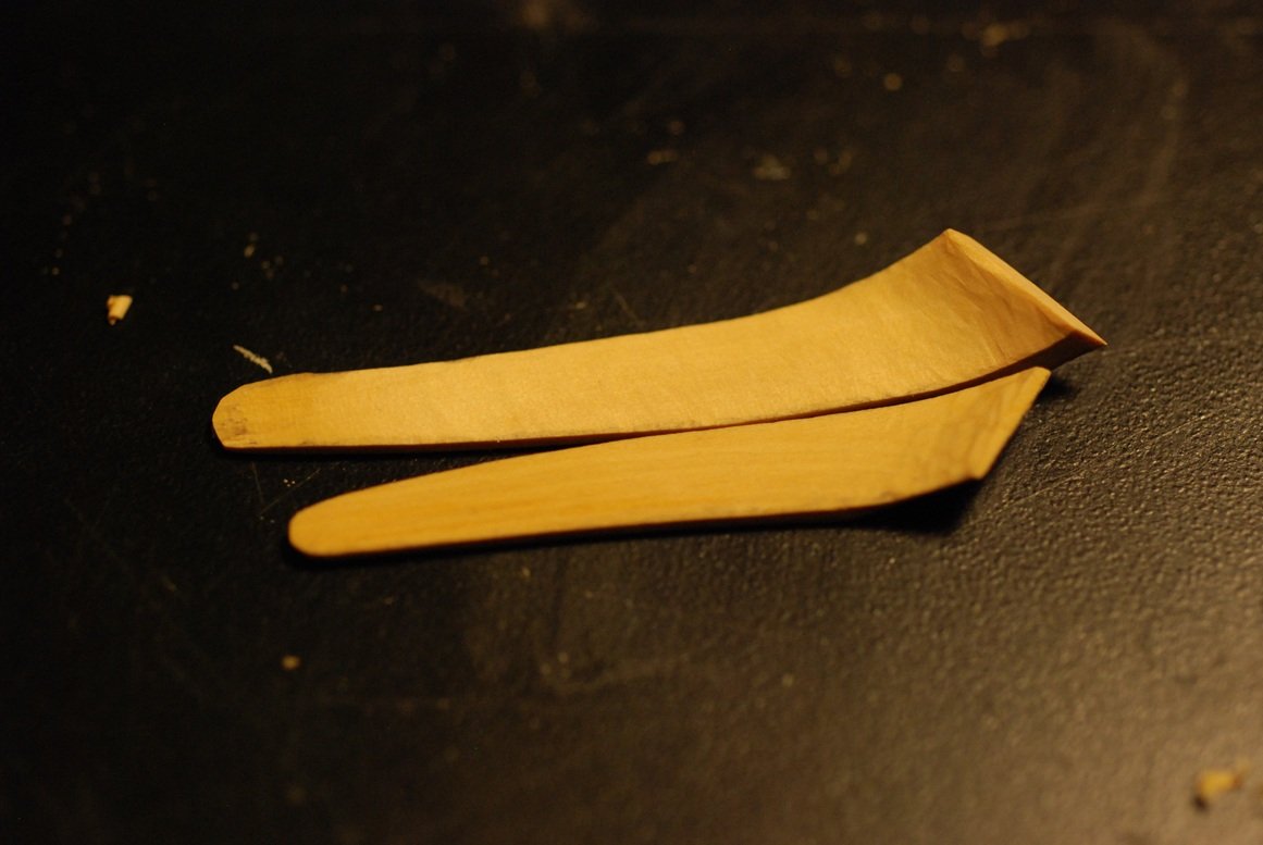
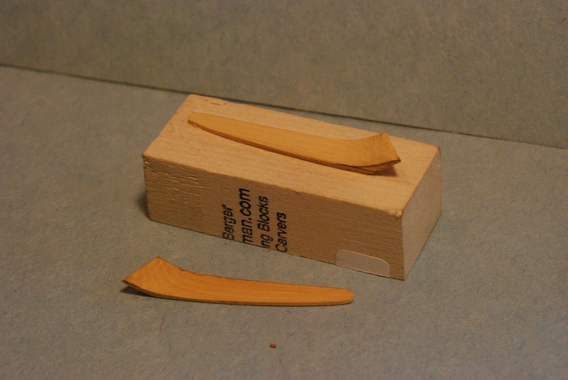
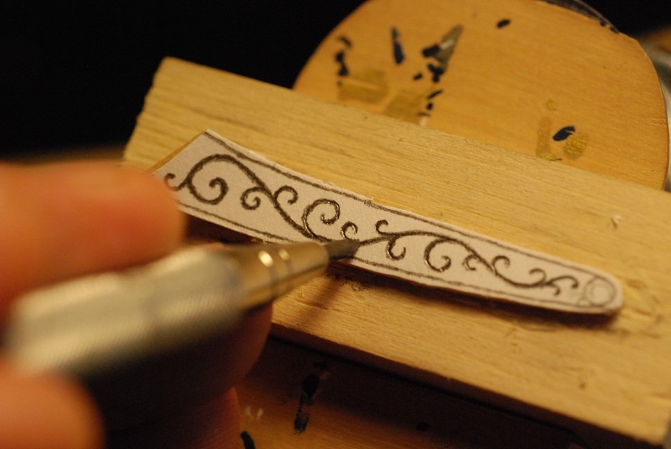
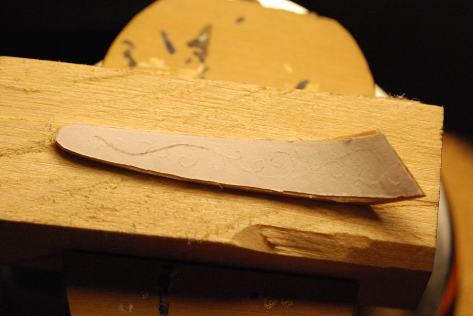
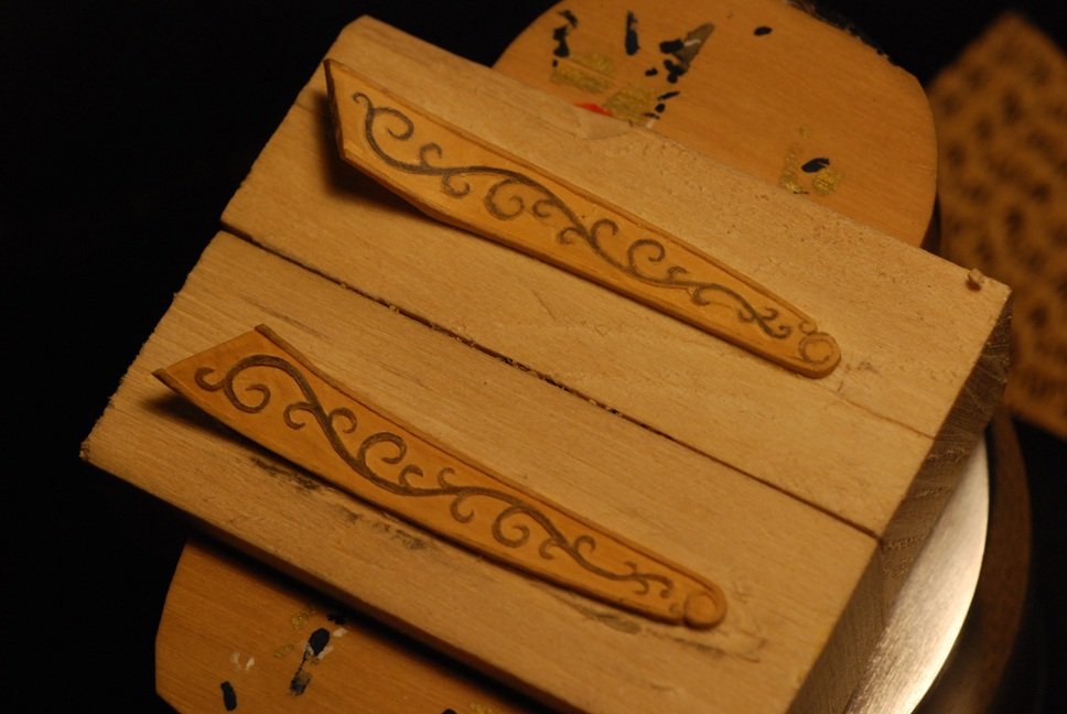
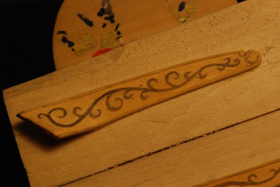
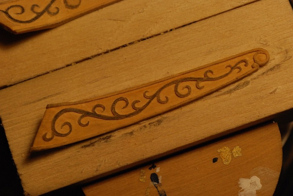
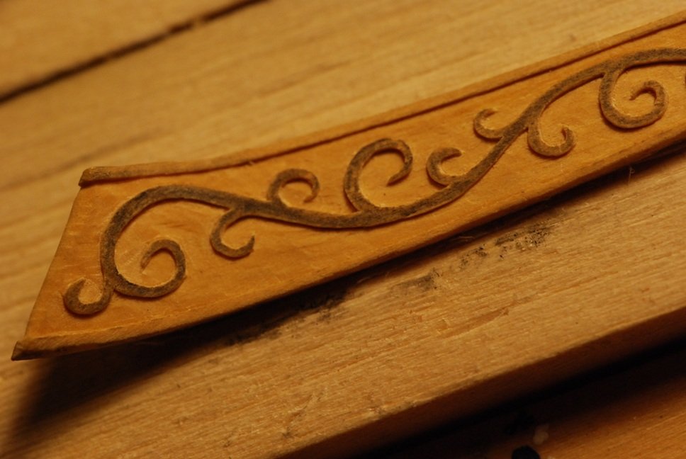
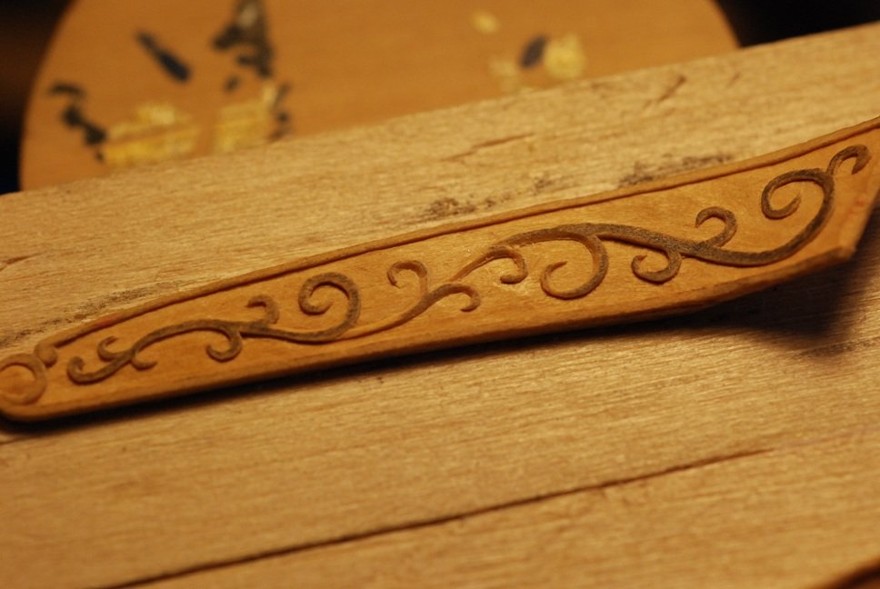
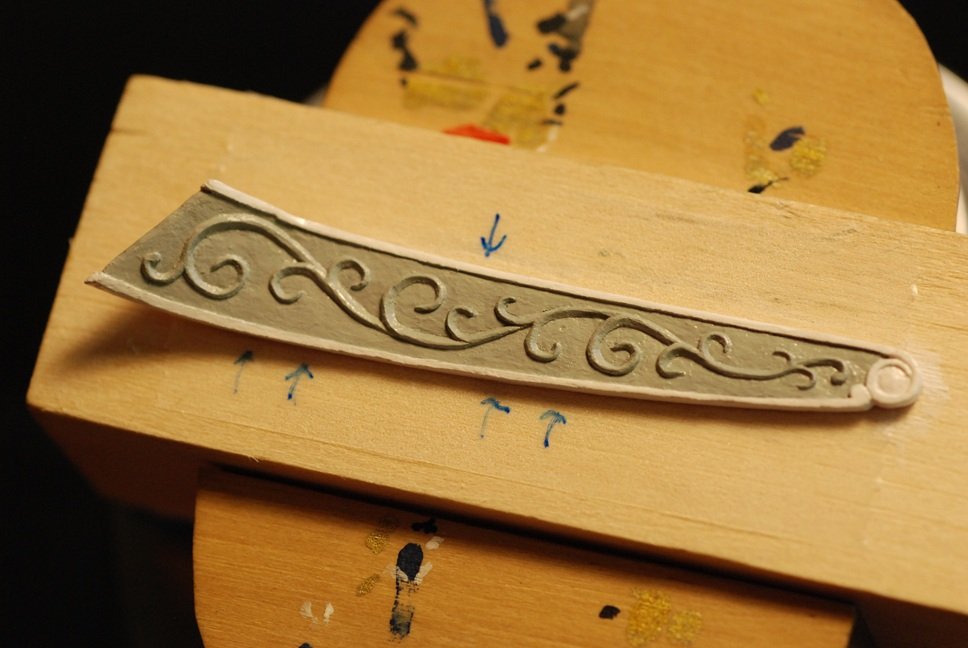
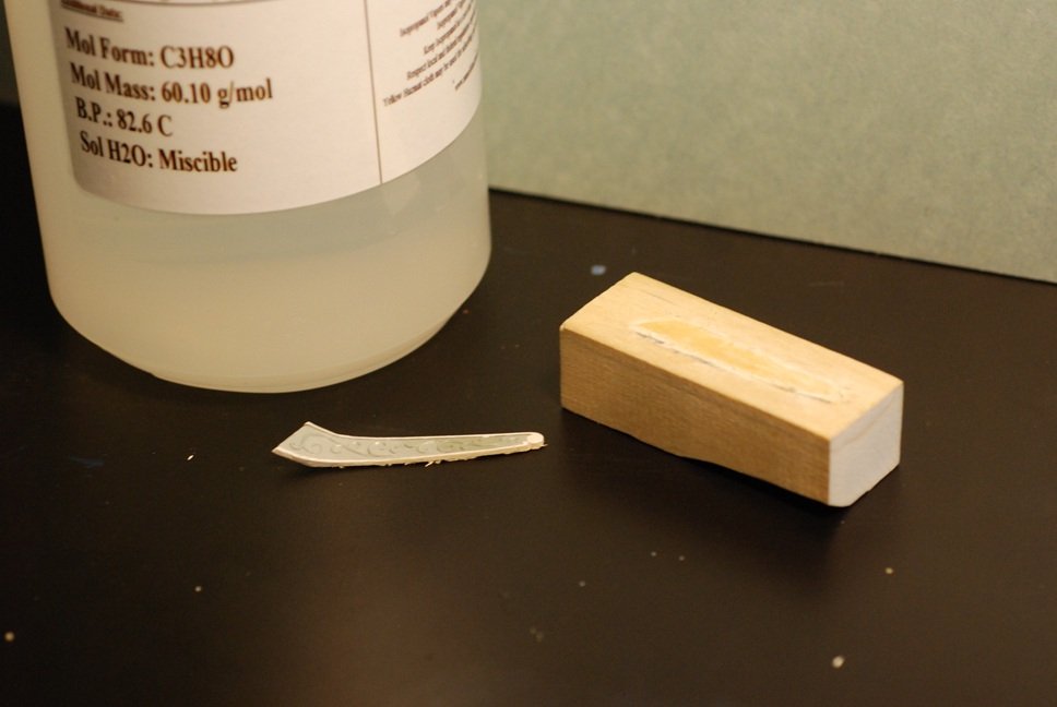
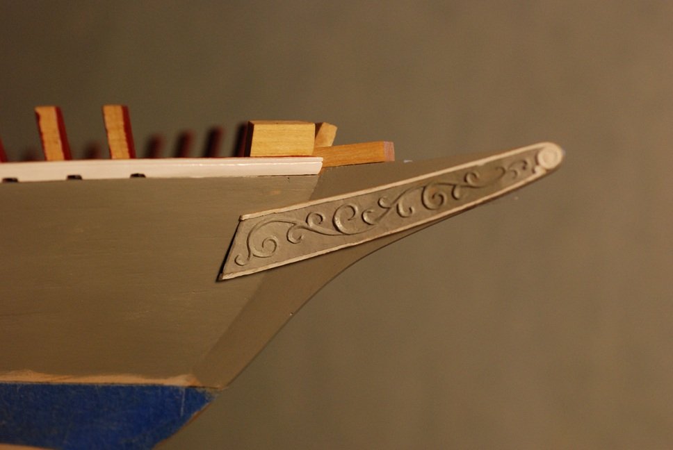
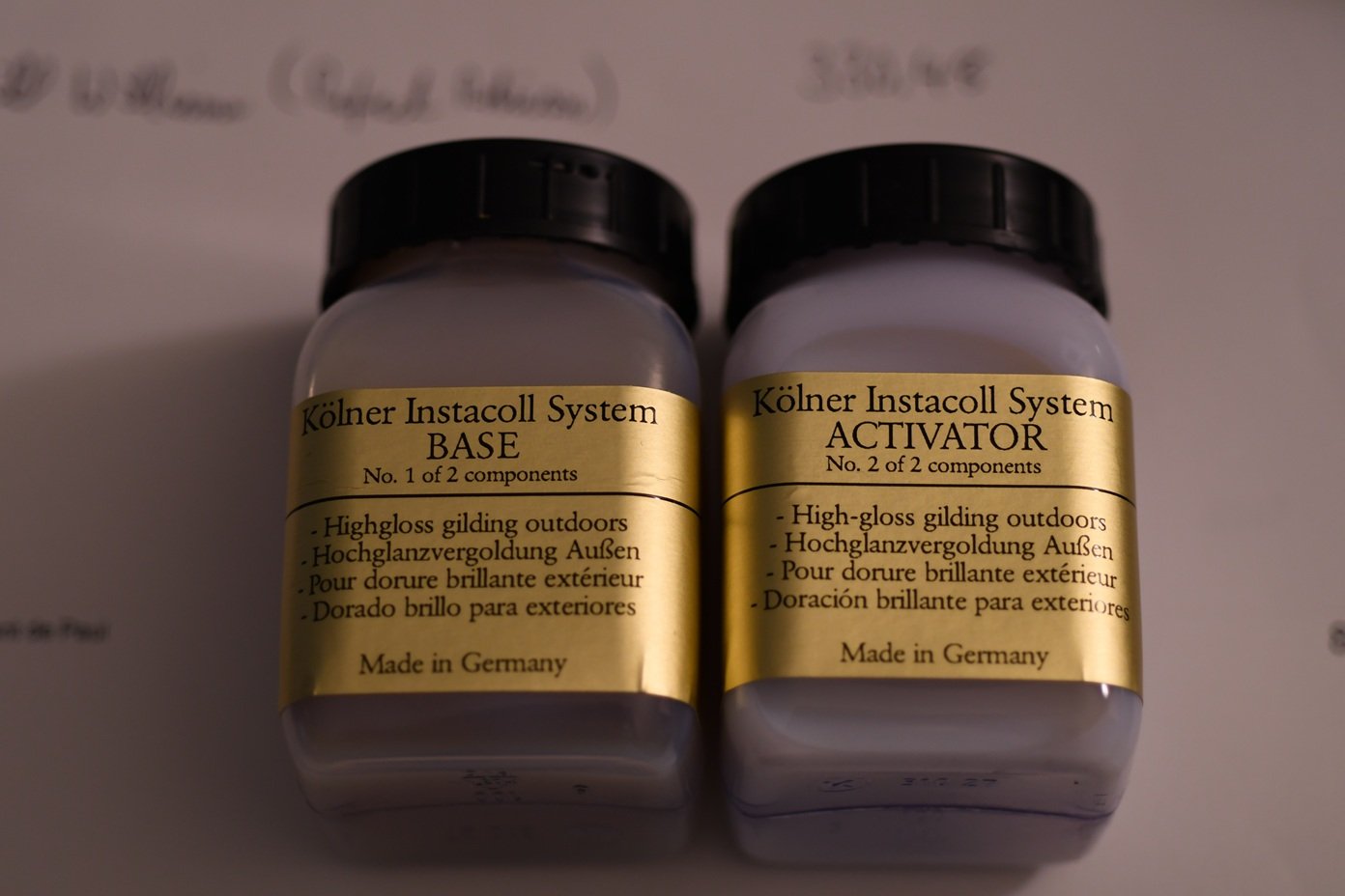
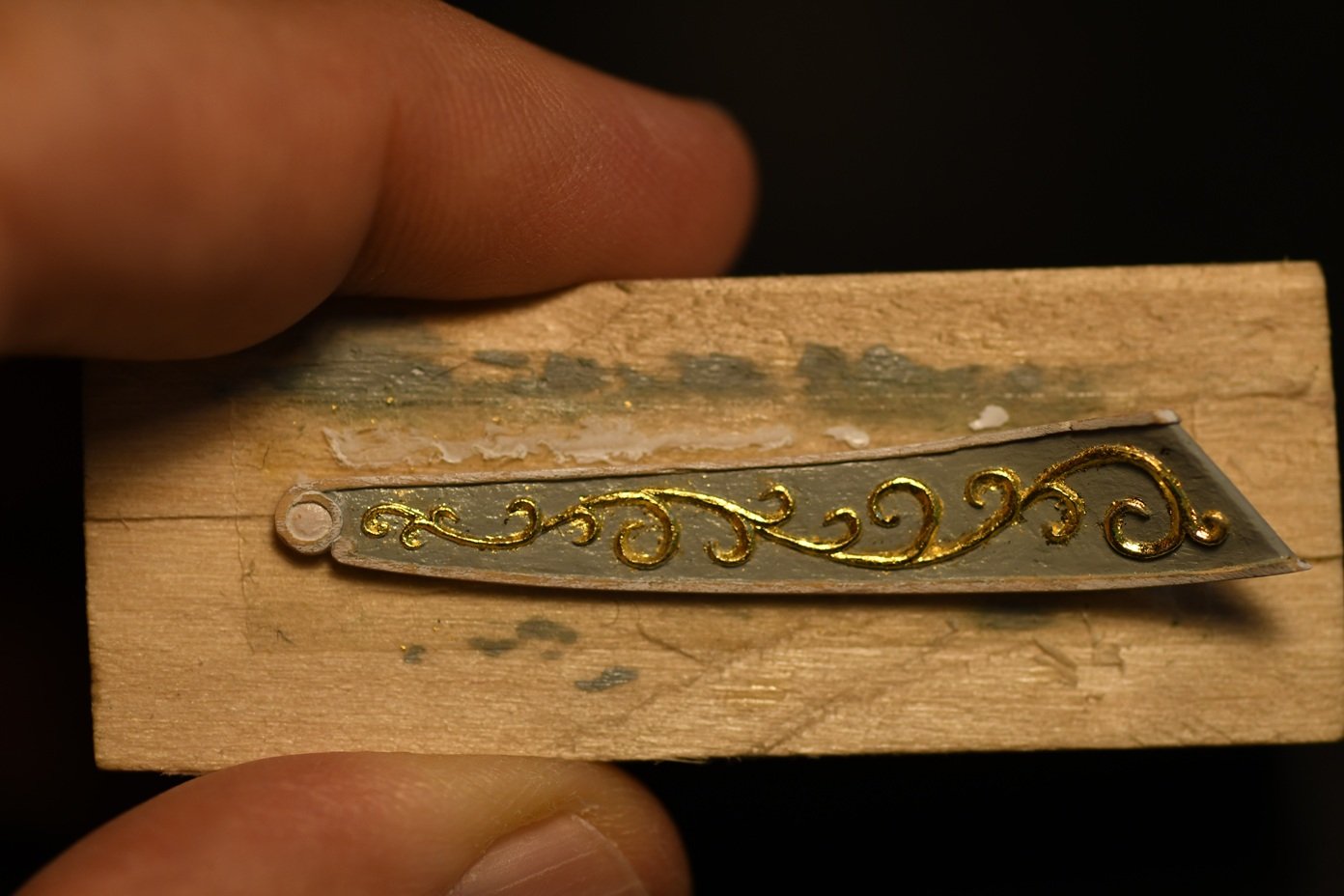
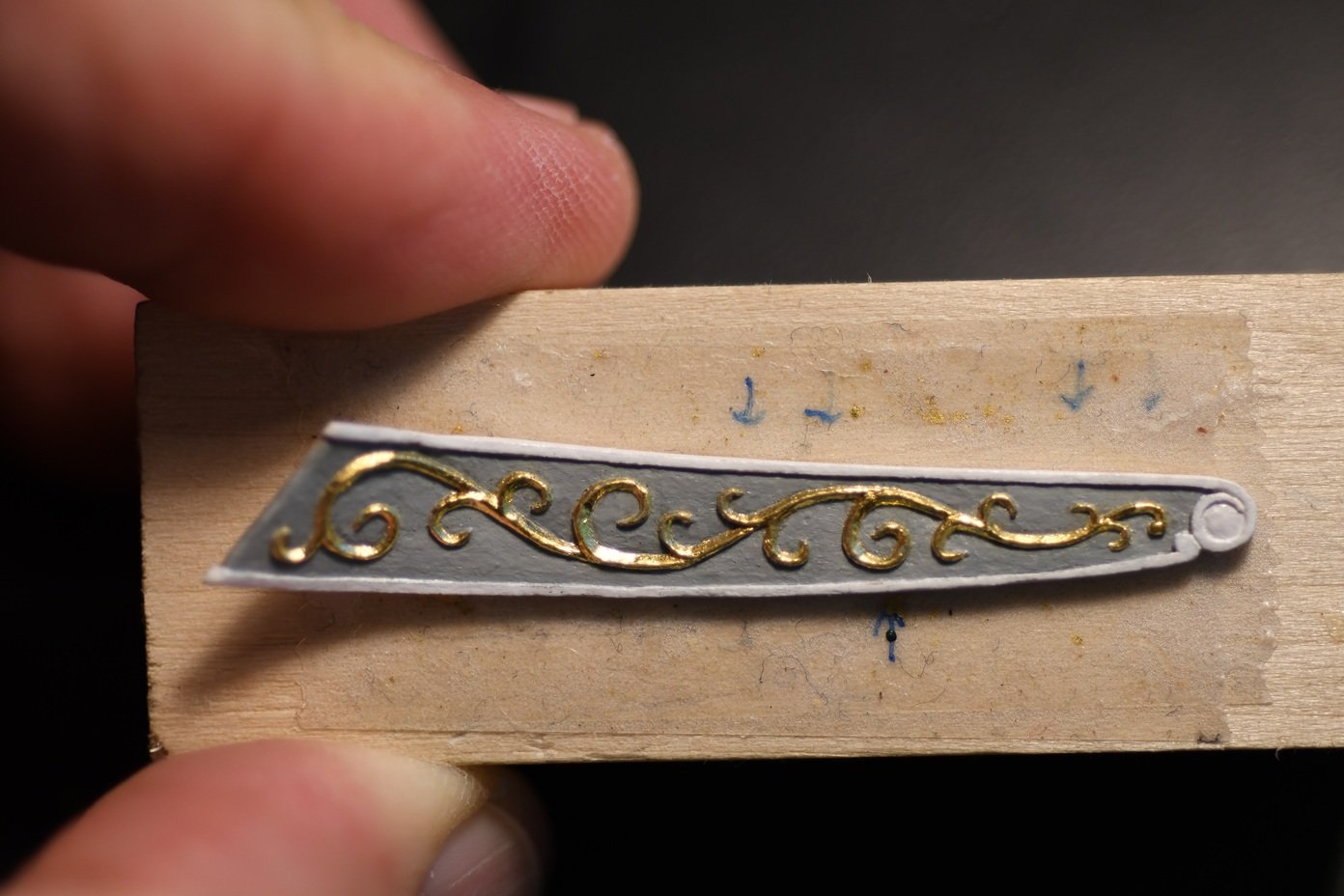
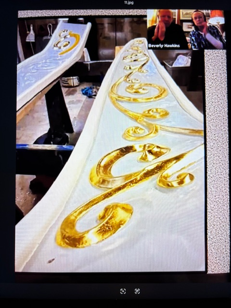
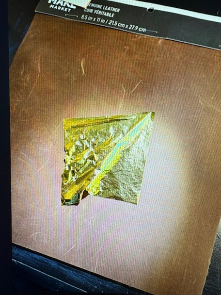
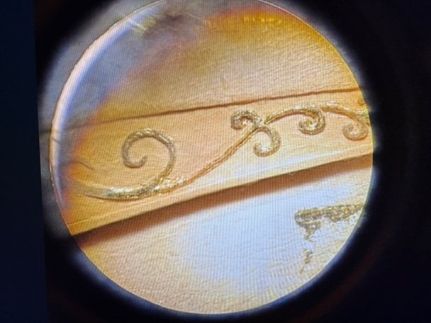
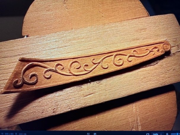
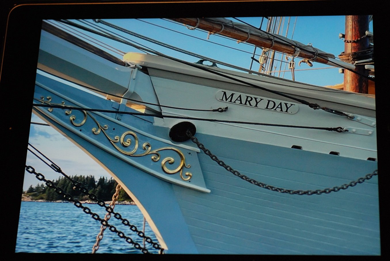
In addition to working on this model of the Mary Day, my other particular creative interest has been in small-scale carving. So it’s nice to be able to have the chance to add some carvings to this model project, such as the transom carving that was covered in a previous post. Here I will focus on the trailboards that are mounted at the bow. The first step was to create a piece of wood that closely conformed to the stem and the adjacent hull shape. Then the outboard surface of the trailboard was carved into this piece. And this had to be done twice, with reasonable symmetry, while also keeping each piece in proper scale relative to the hull and stem. After working out the gross shape of each trailboard and test fitting them on the hull, they were each mounted on holding blocks with glue. The scrollwork was drawn with soft lead pencil, using freehand technique while having actual photos of the trailboards close at hand. The drawing was then inverted and transferred to each workpiece using a hard lead pencil. The detail was then filled in prior to beginning the carving process. Also outlined were the margins of the trailboard and the decorative scroll at the tip of the trailboard. Using the microscope, the background was carved away, leaving the scrollwork and the margins at the top and bottom edges of the trailboard. At this point I felt very proud of myself… …until a fellow modeler pointed out that if left as is, the scrollwork would look like piped-on icing on a birthday cake. (My son who works in digital animation agreed with this assessment!) In order to fully resemble the actual trailboard, the scrollwork would need contouring that resembles the actual trailboard, shown here as they receive a new layer of gilding. I initially doubted that I had the skill to duplicate this at such small scale. But with the right tools and adequate magnification, it was possible to carve out bevels on the concave surfaces of the scrollwork, while rounding the convex ones. The entire surface was painted the same shade of gray as the hull surface. The piece was parted from its backing using alcohol, and was test mounted on the hull and stem. Instead of painting the scrollwork with gold colored paint, gilding was recommended. This was a new process for me. Just learning how to handle the fragile gold foil took some practice and some review of YouTube videos! And don’t have the air conditioning blowing too much in your work area… There is a product line out of Germany made by Kolner, called the Instacoll system. It involves an adhesive base that is applied and allowed to dry. Then an activator is applied, followed by application of the gold foil. The foil is then burnished down to the surface. I had a spare trailboard with carving on it that allowed for some testing of the system before moving to the actual pieces. Here is a trailboard that has been gilded, with excess gold leaf on the background. And here is one that has been fully cleaned up, with the excess gold leaf scraped off of the background. Hopefully my next post will follow pretty quickly, regarding the bulwarks planking. Stay tuned!
-
Oh good! I have been wondering if the boxwood had been incorporated at all yet.
-
Wonderful news from Donna!
-
If you figure out what the name is for that unusual ruler is, be sure to let us know! I am not finding anything like it on my initial searches.
- 969 replies
-
- 2
-

-
- hahn
- oliver cromwell
- (and 1 more)
-
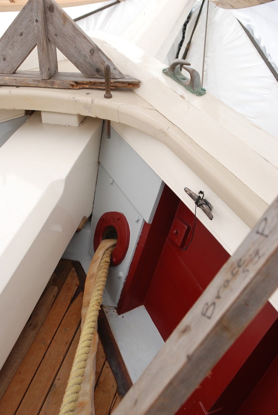
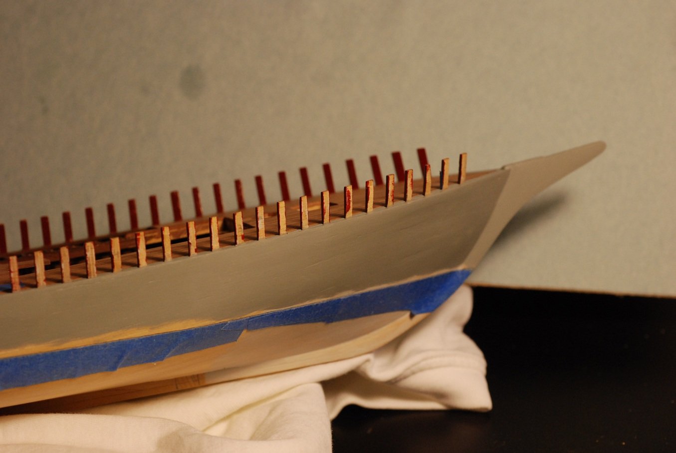
Just a brief post to let you all know I am still alive. The subject is the hawsepipes, and this was a perilous adventure! Even though I have finished the process, I am curious to know how others handle such a delicate matter. The entry point on the knighthead has to be precisely located, as does the exit from the hull planking. I started with very fine drill bits and estimated the path the pipe should follow, drilling in a very shallow manner starting at the knighthead, then doing the same starting at the hull surface, then deepening each hole with the hopes that they would meet in between. While I was still working with relatively small bits, I could tell I was off on the starboard side, as the pipe was emerging too low on the hull. But as I gradually scaled up, it became possible to work on the pipe with the tip of an X-Acto blade and open up the passage in a favorable direction. And in the end, I ended up with two symmetrical passages. The diameter is currently 1/16". They will probably still require further enlargement, and additional wood will be applied to the inboard and outboard surfaces to duplicate the appearance on the real vessel. That will be helpful in that it can potentially cover up other imperfections. So how does everyone else handle this delicate matter?


-
Wow Mark, that looks great!
-
Congratulations, Mark! I will particularly remember the tip about the Army Painter Wet Palette.
-
Wefalck, that book is exactly the reference I have been looking for! Should be immensely useful when looking at Boudriot's books.
-
There's German, and then there's nautical German. And then there is the nautical German translation of the nautical French...or vice versa...
-
Johann, your post takes me to the YLI Threads website. Are you using their Silk #100 thread? Amazing work as always!
-
Wow! Following with great interest, Johann.
-
Thanks, Phil! Looks like I need to add this book to my library.
-
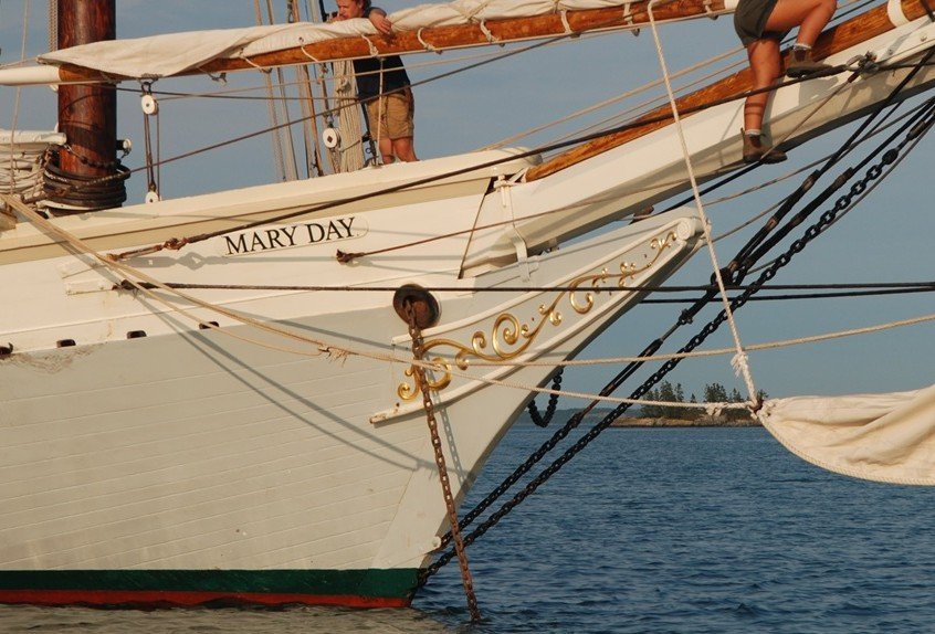
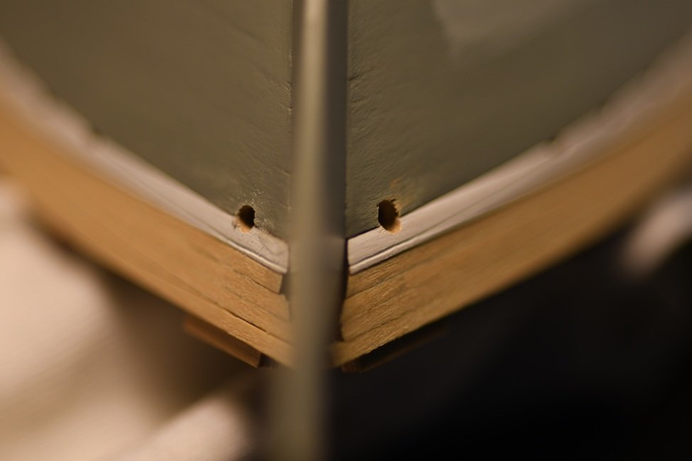
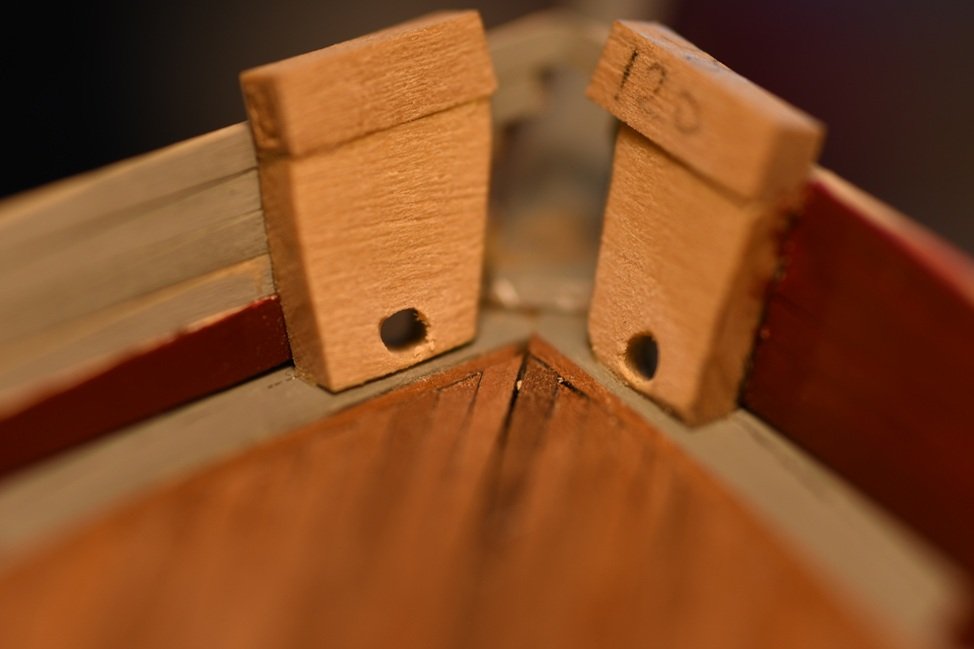
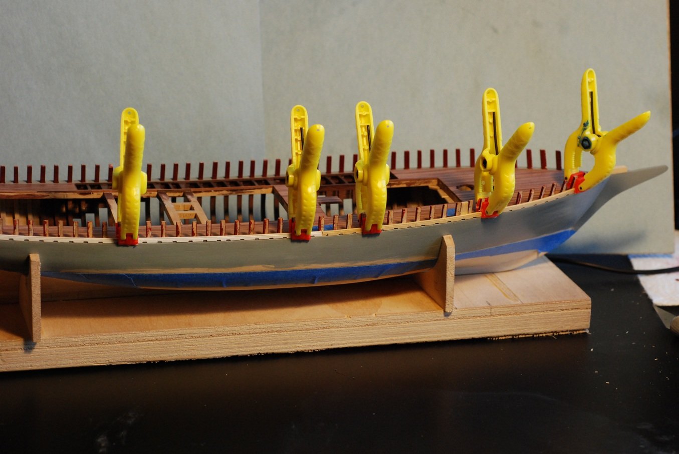
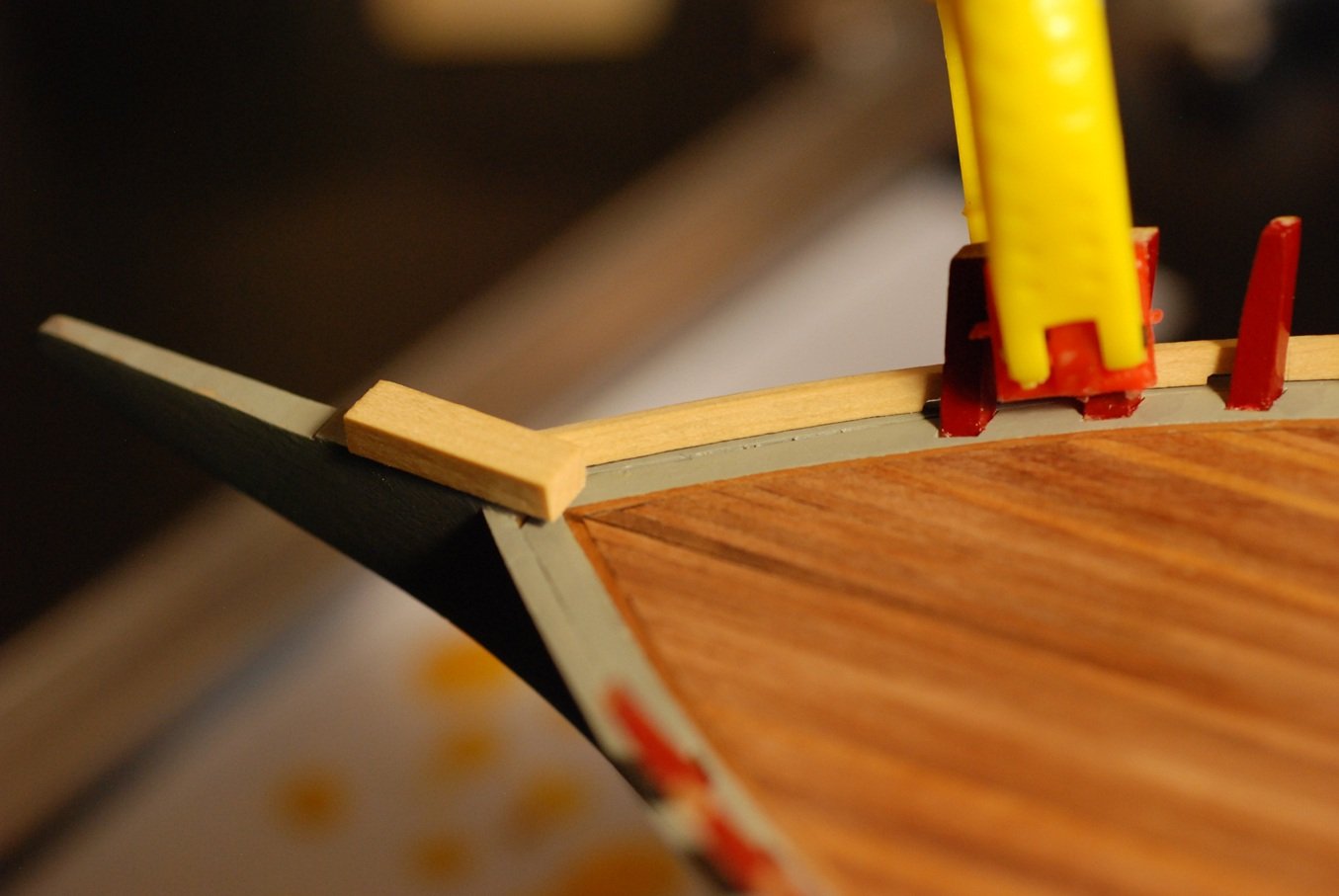
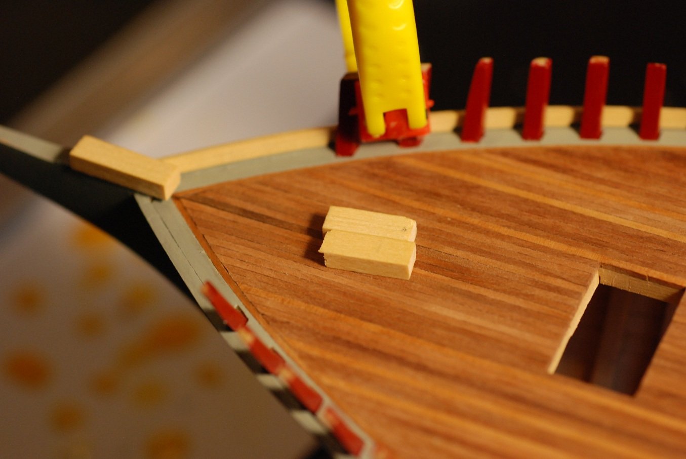
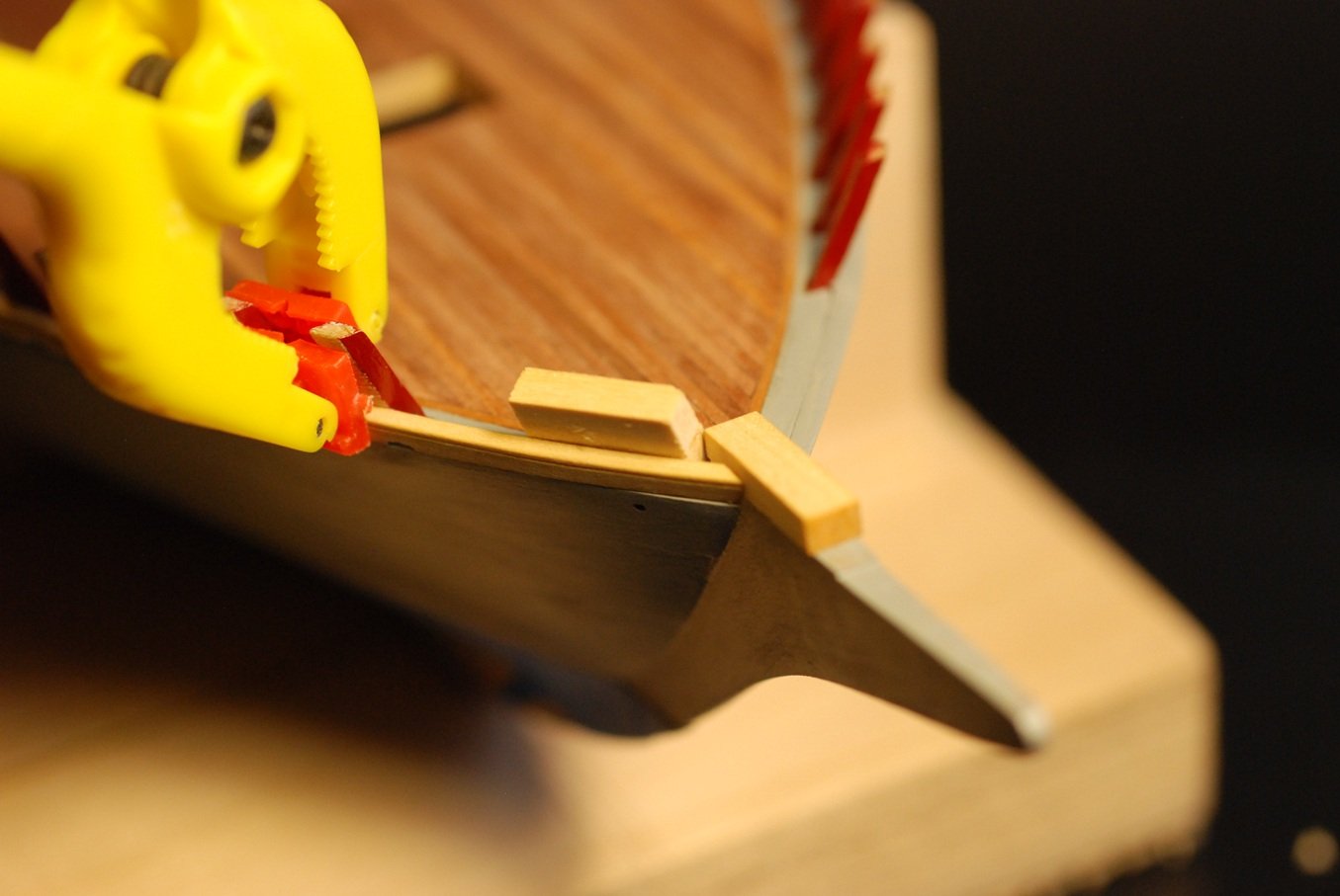
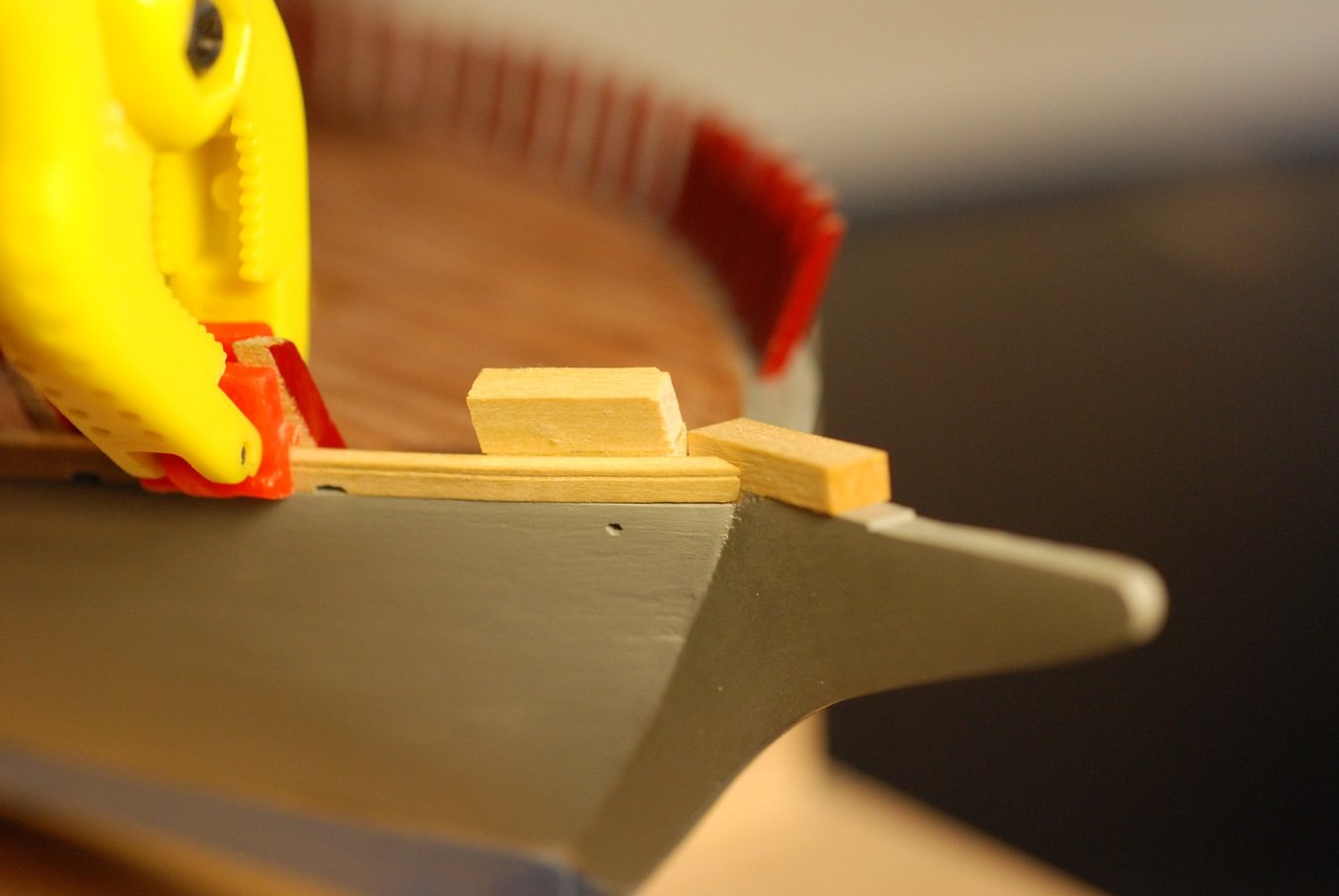
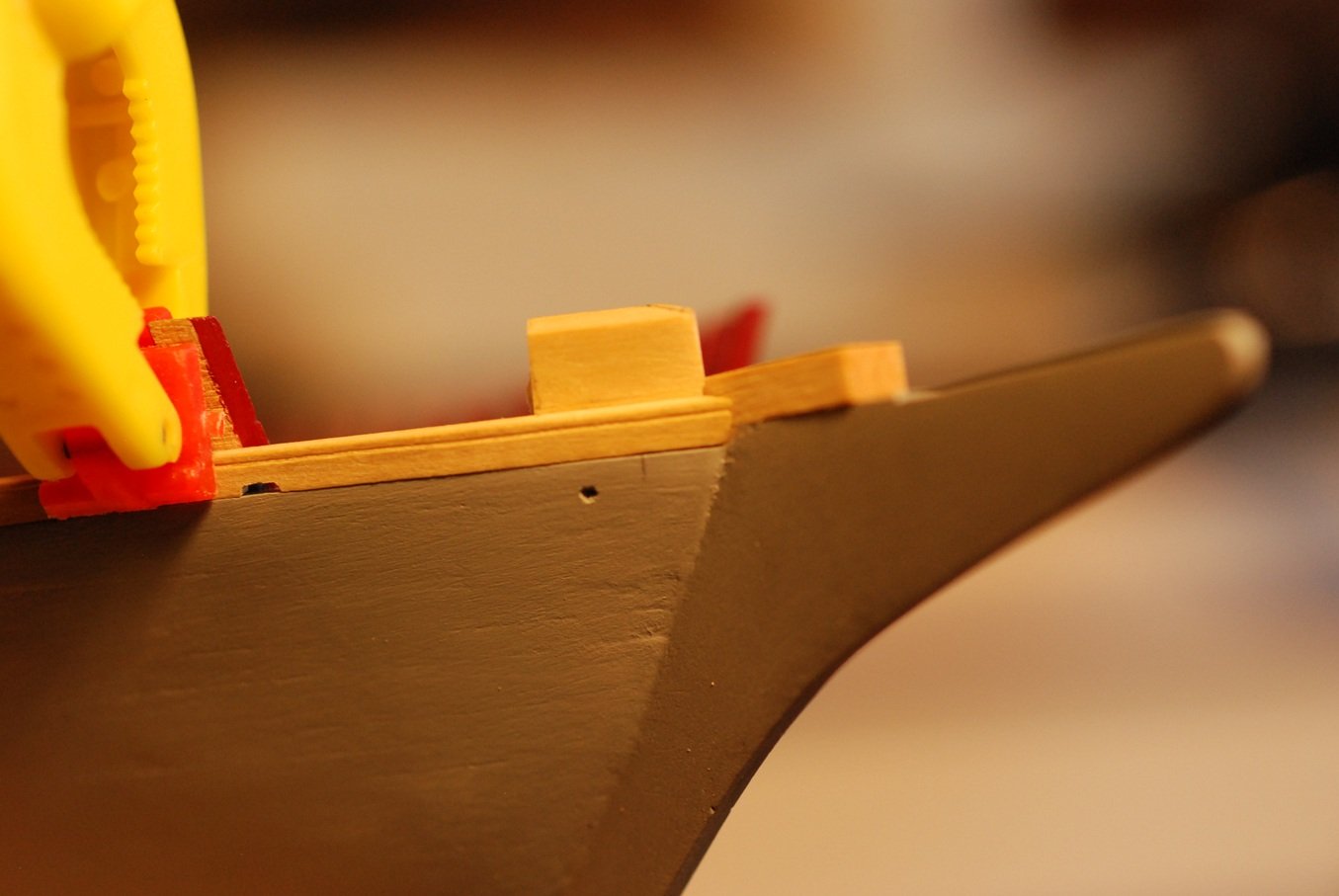
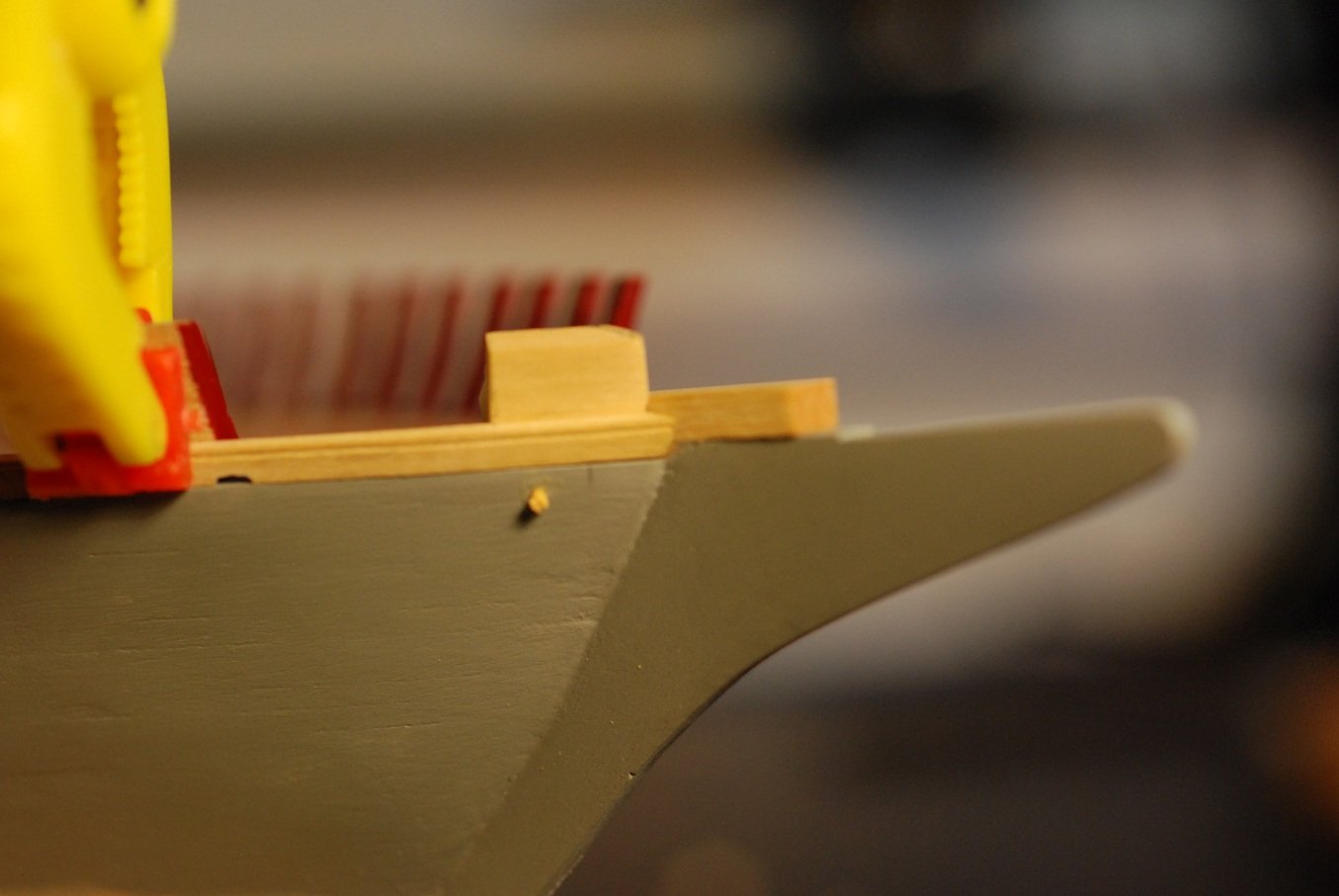
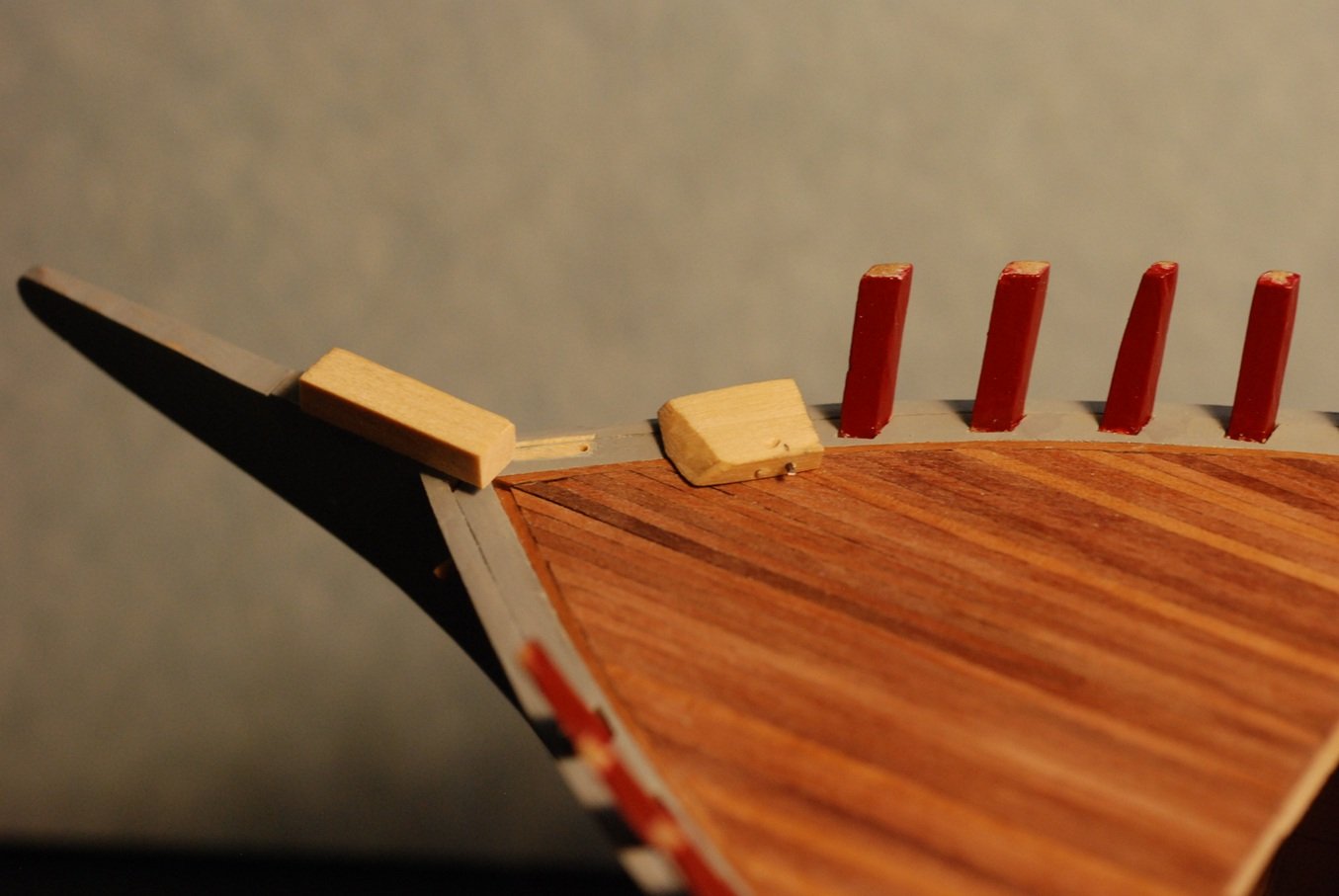
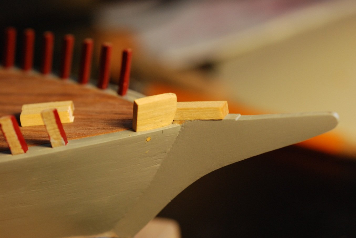
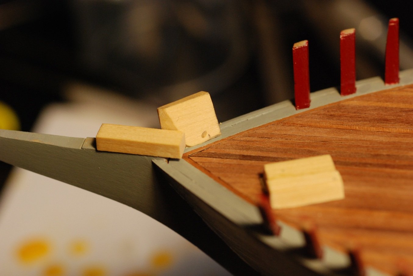
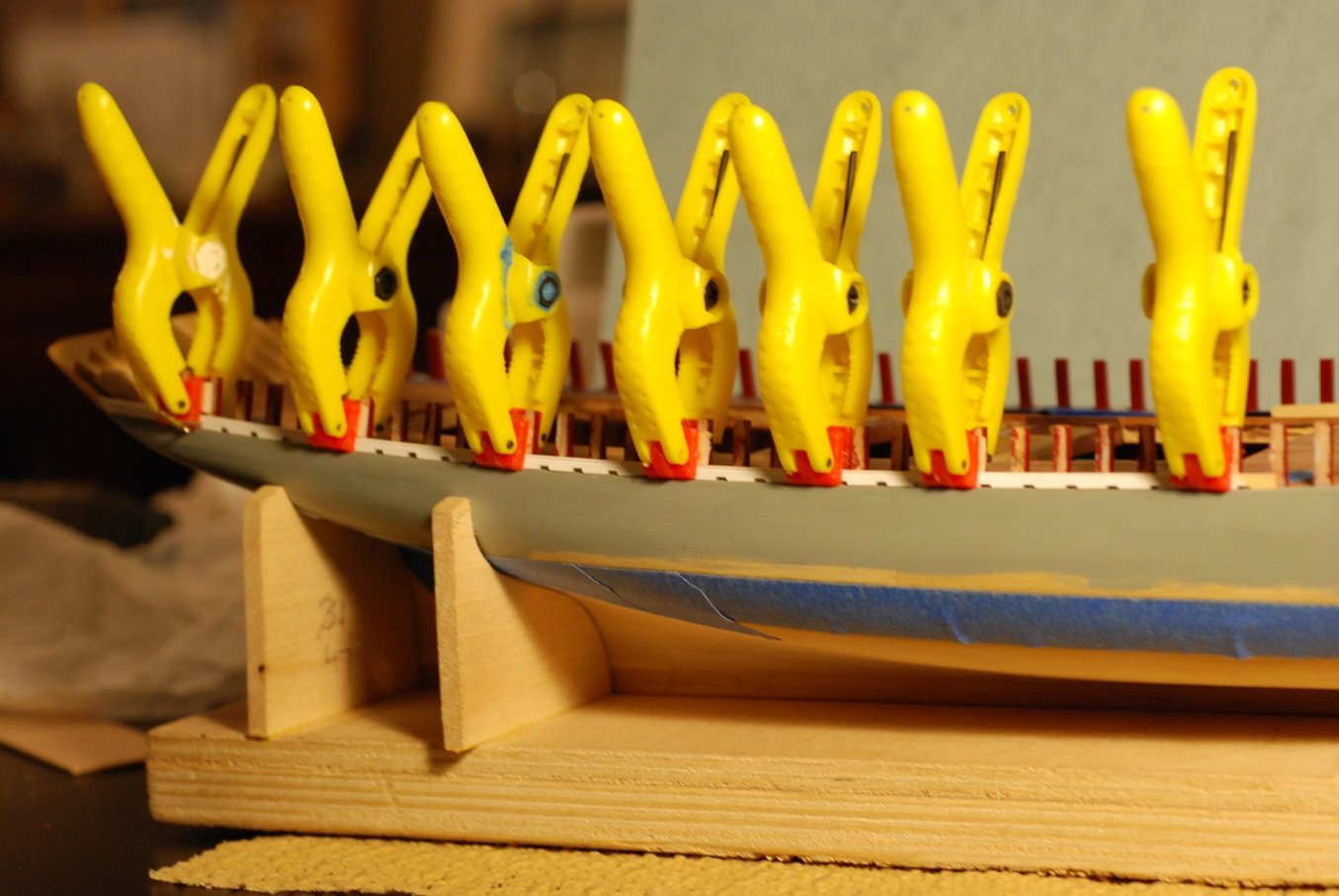
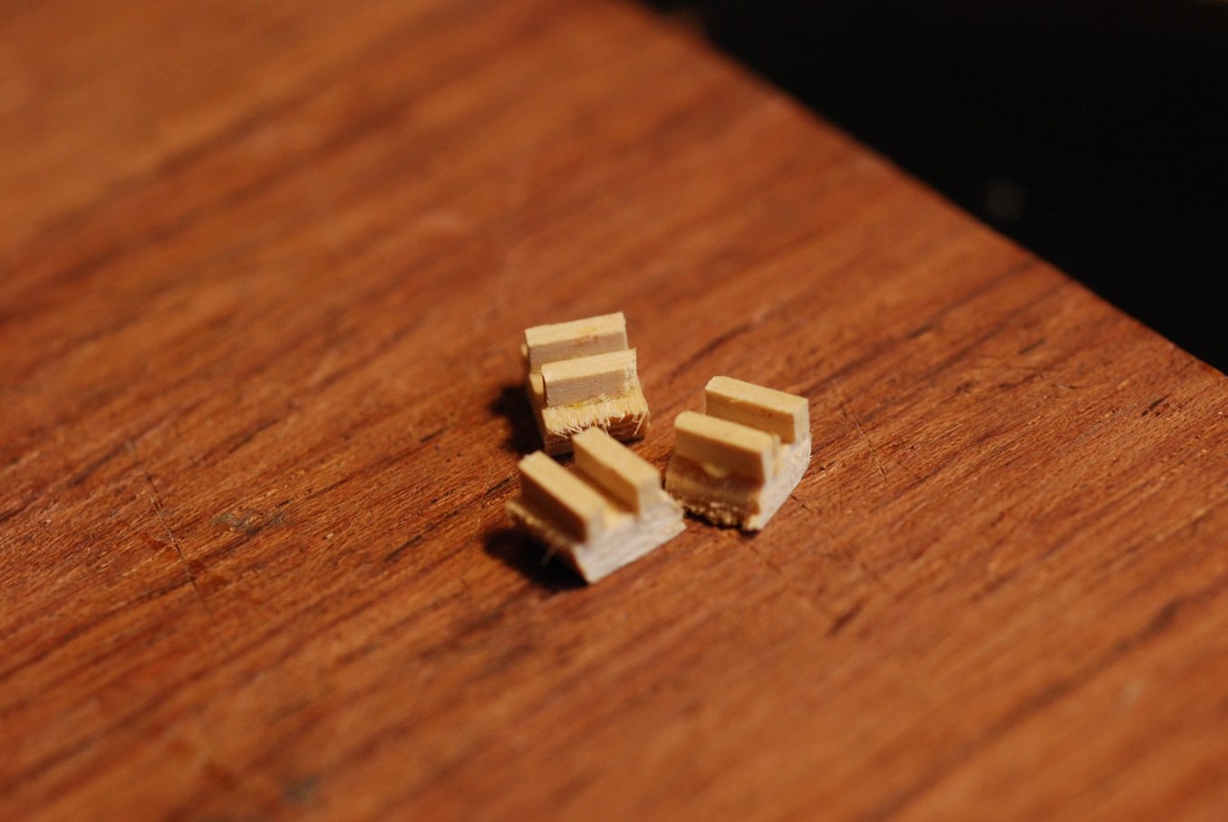
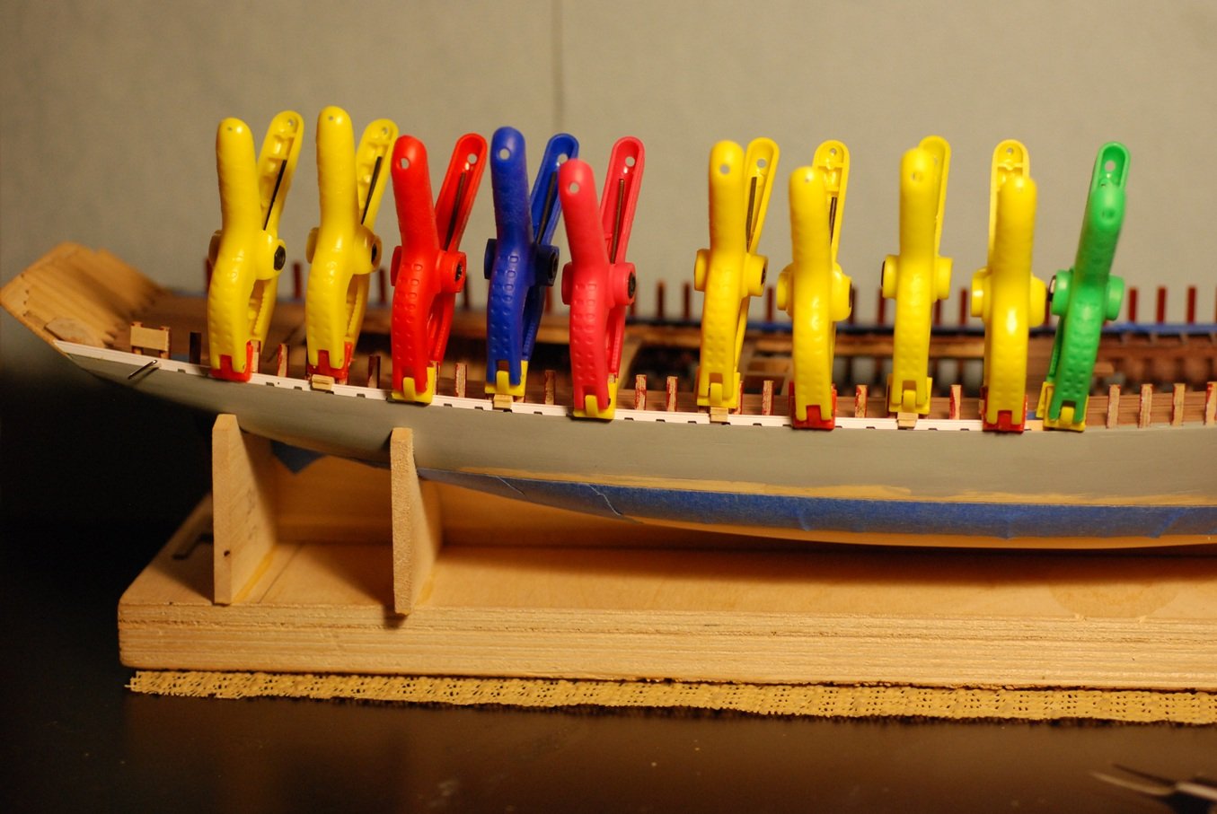
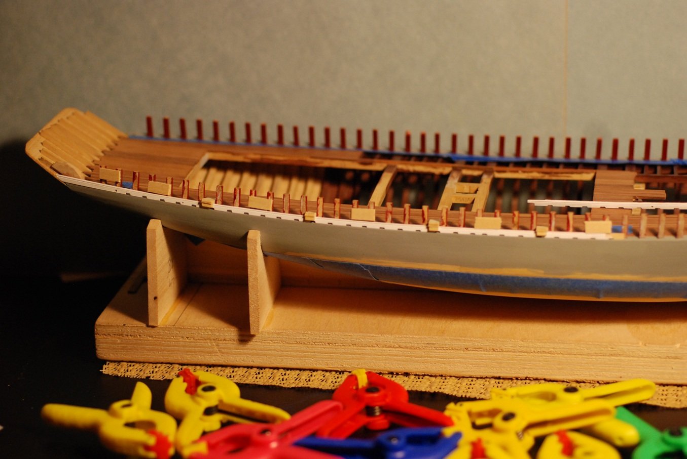
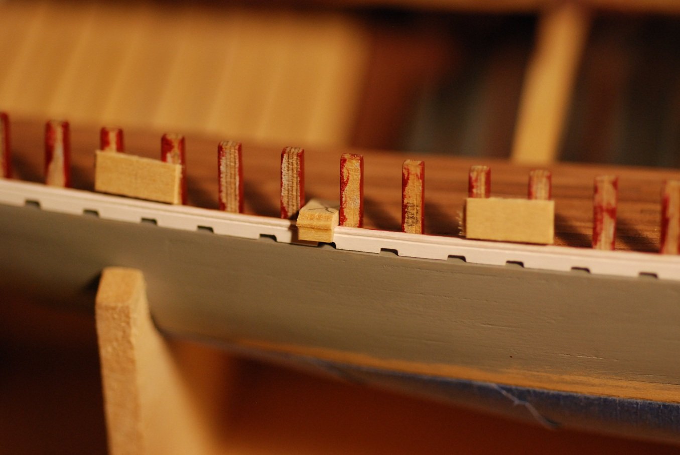
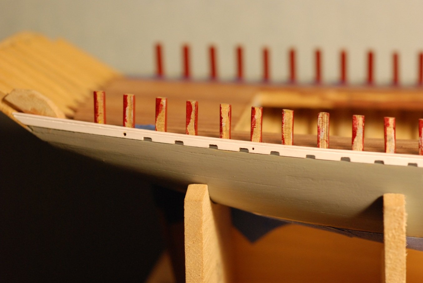
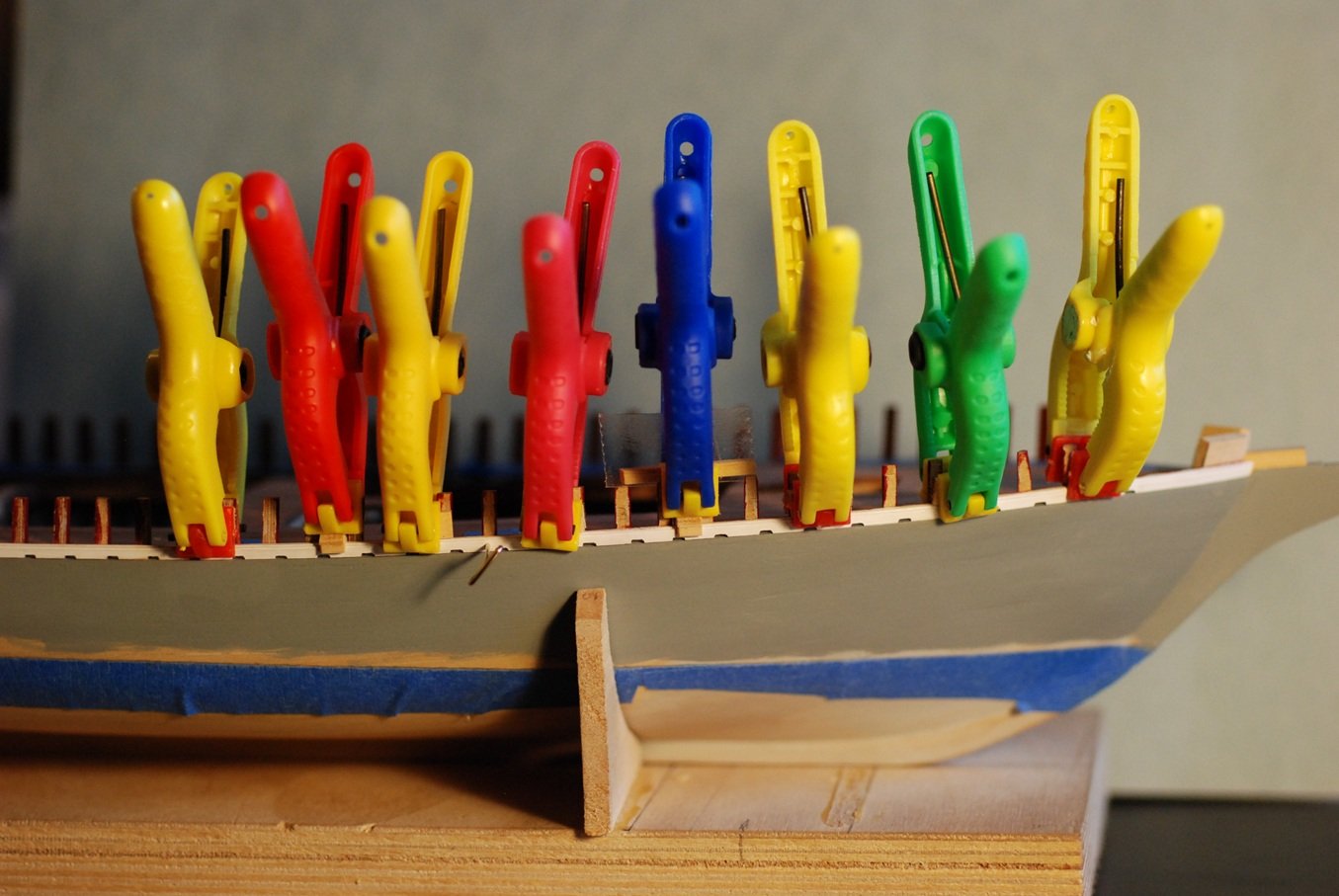
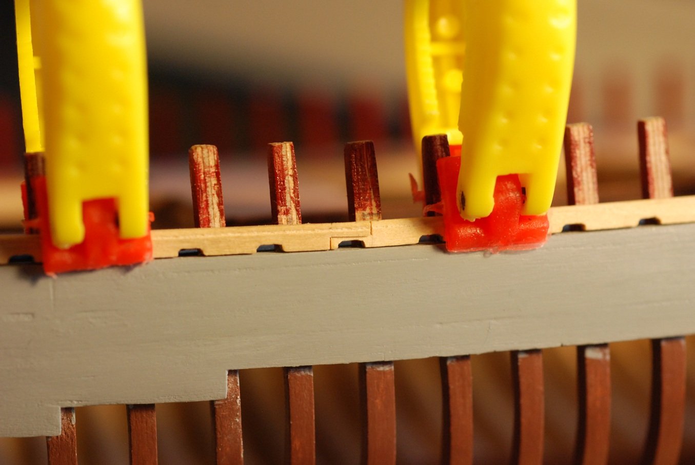
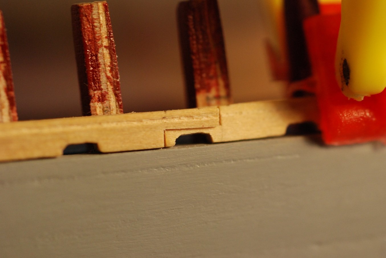
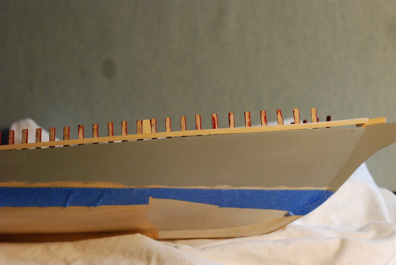
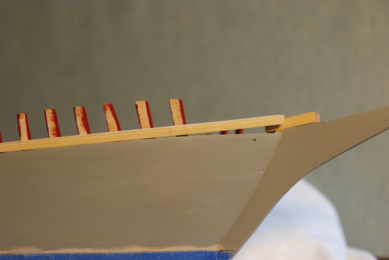
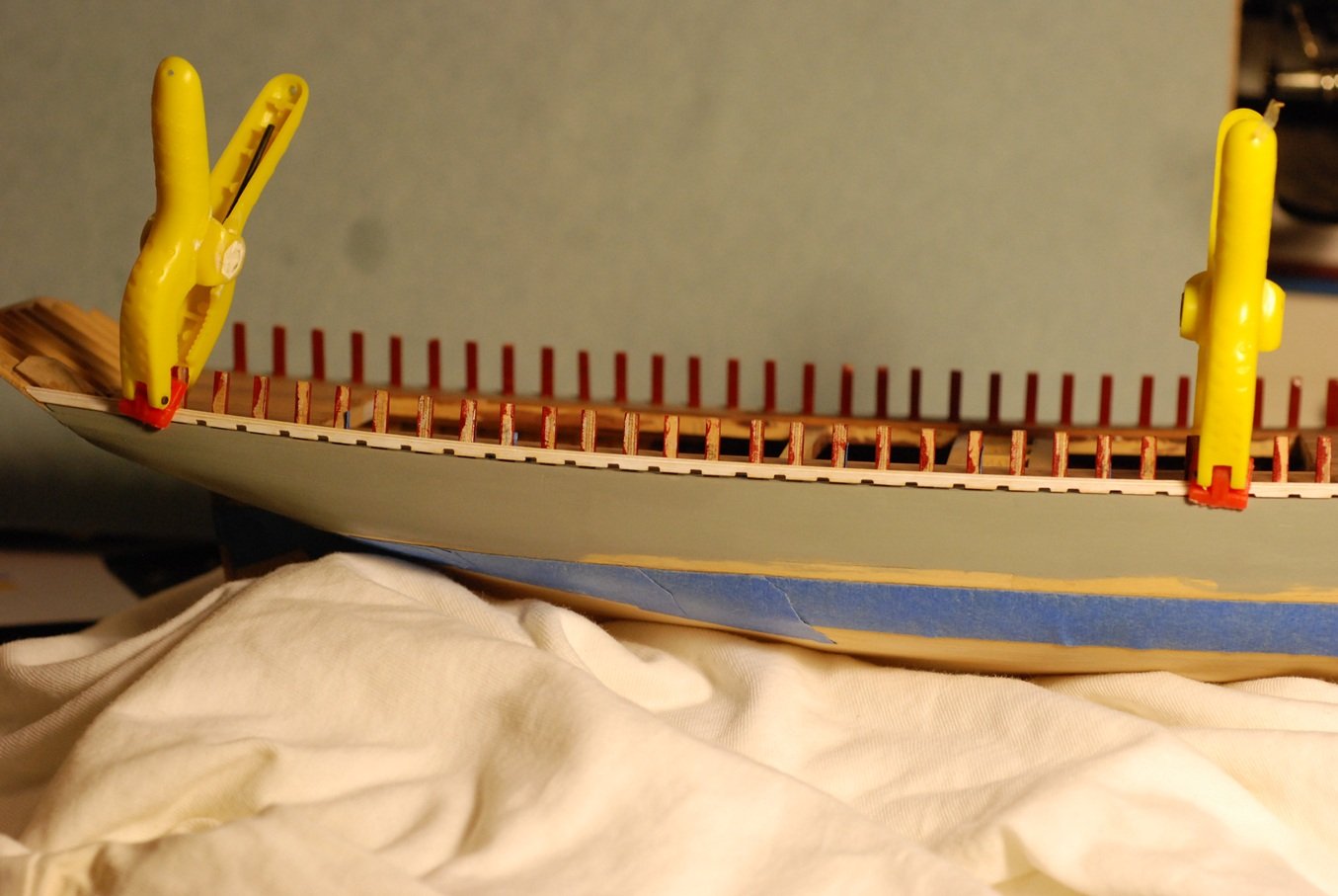
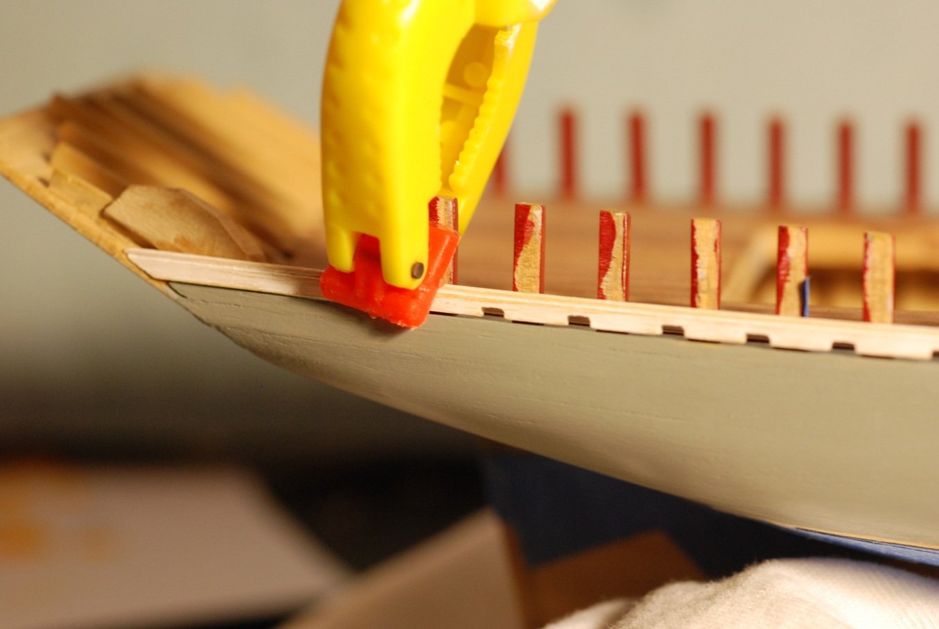
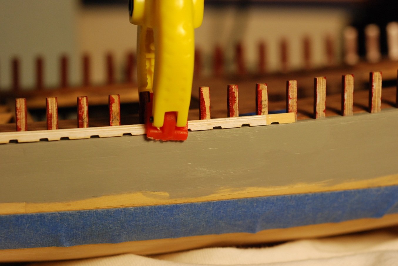
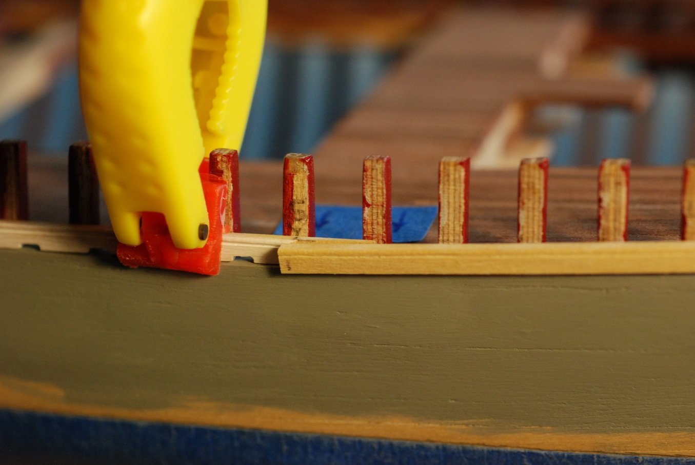
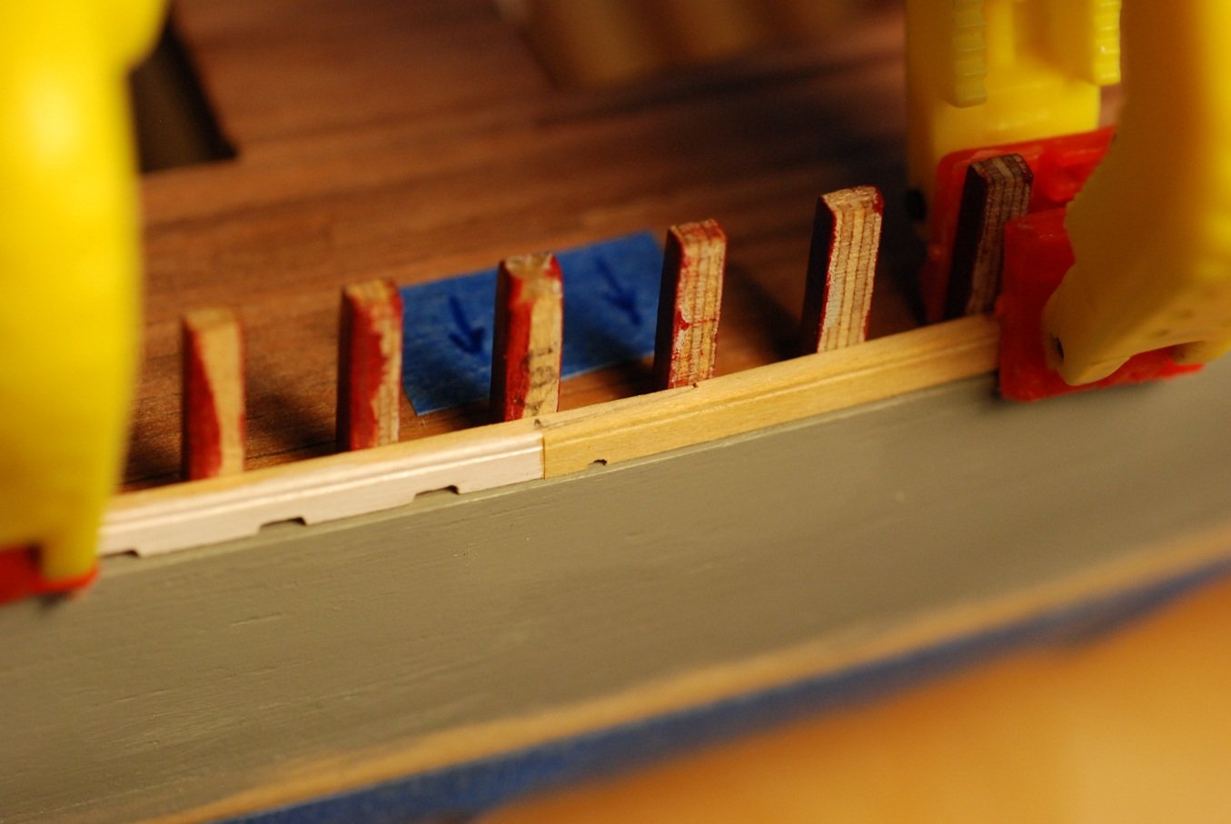
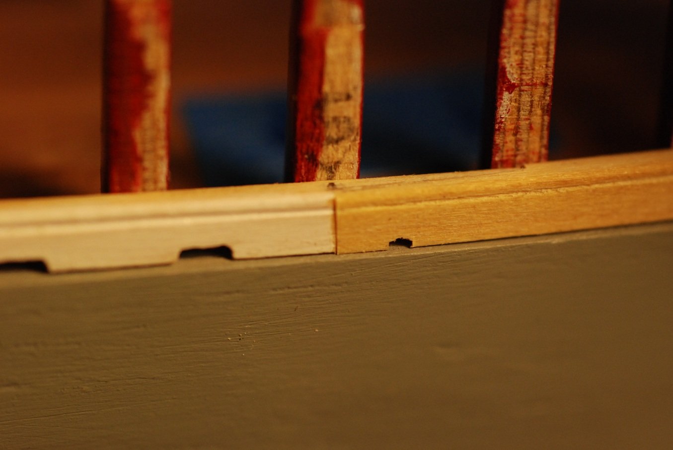
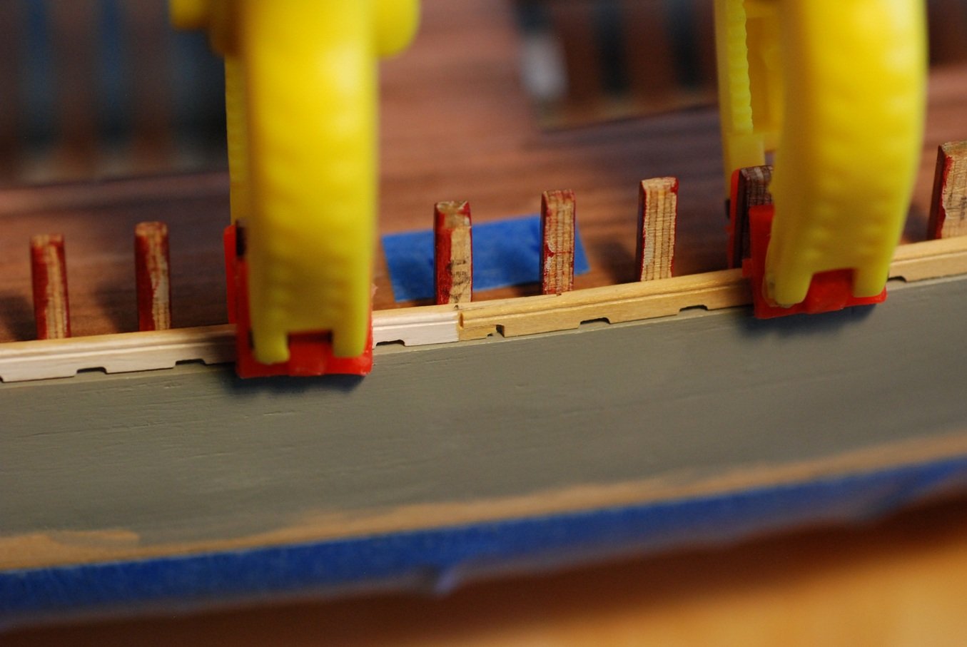
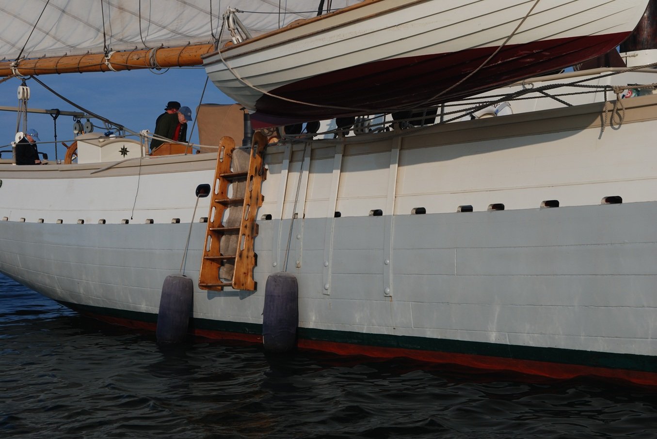
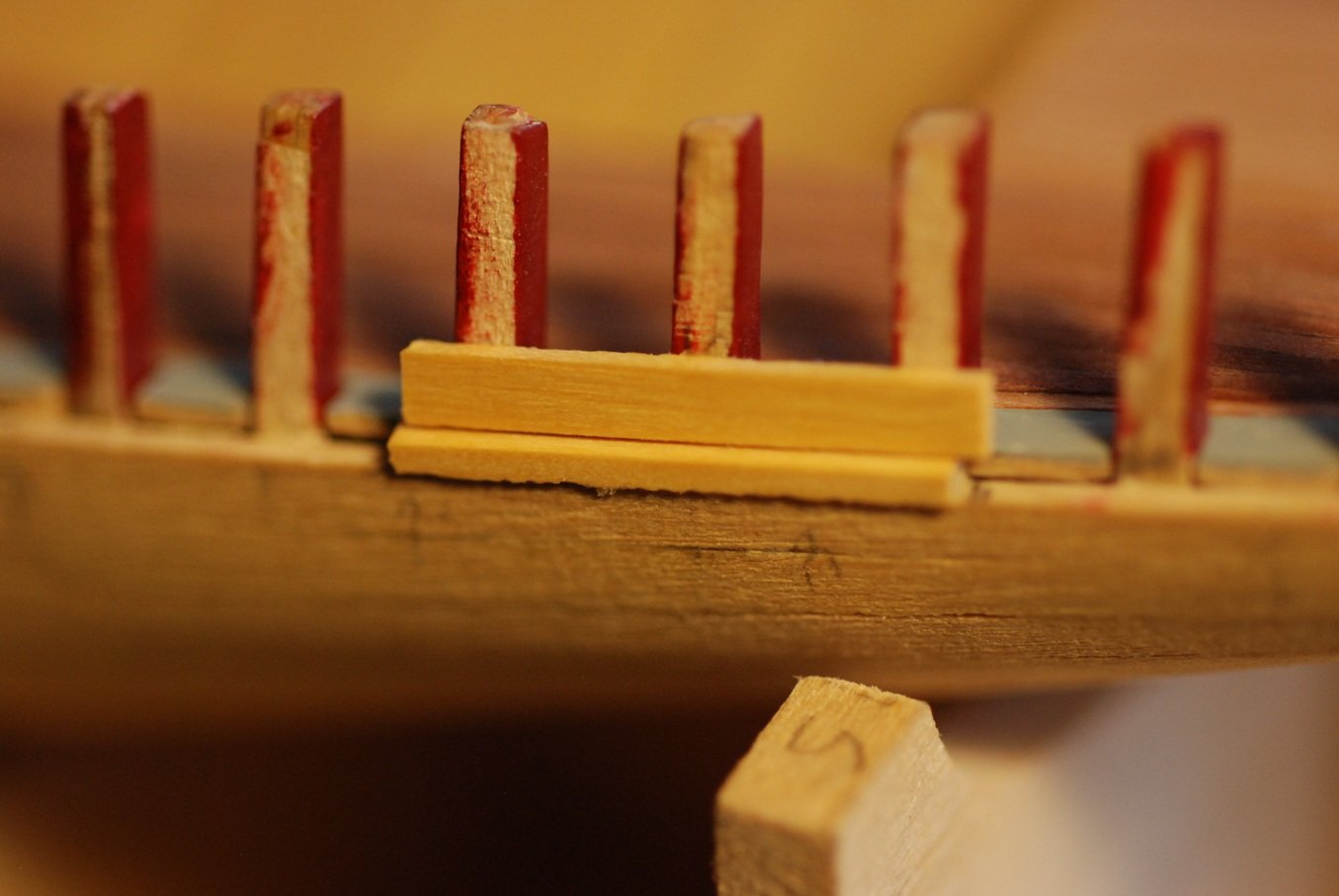
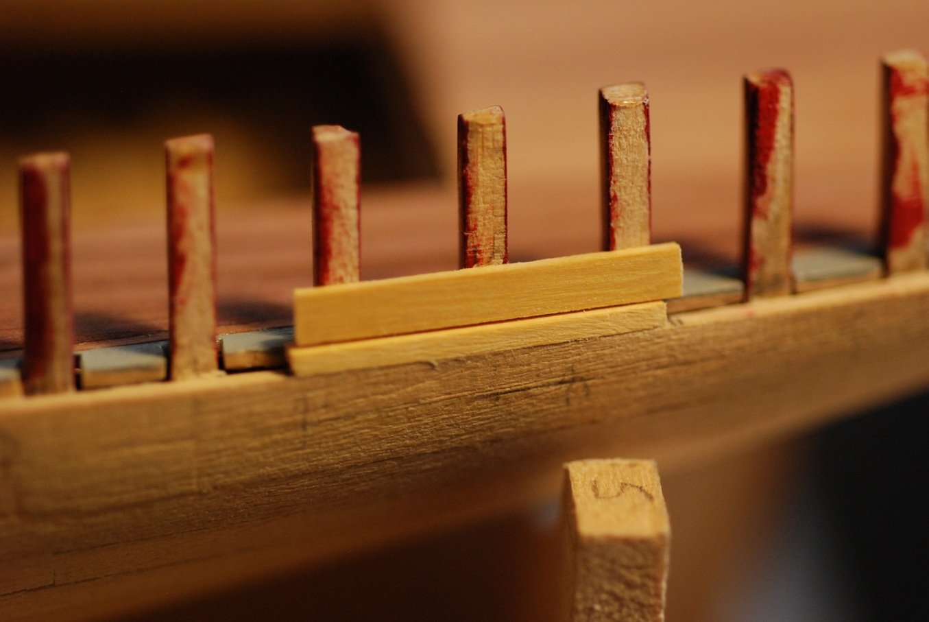
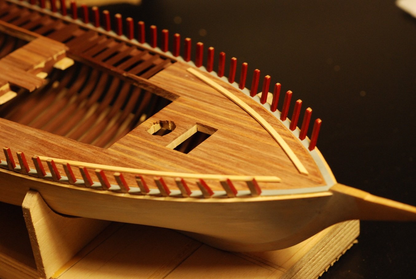
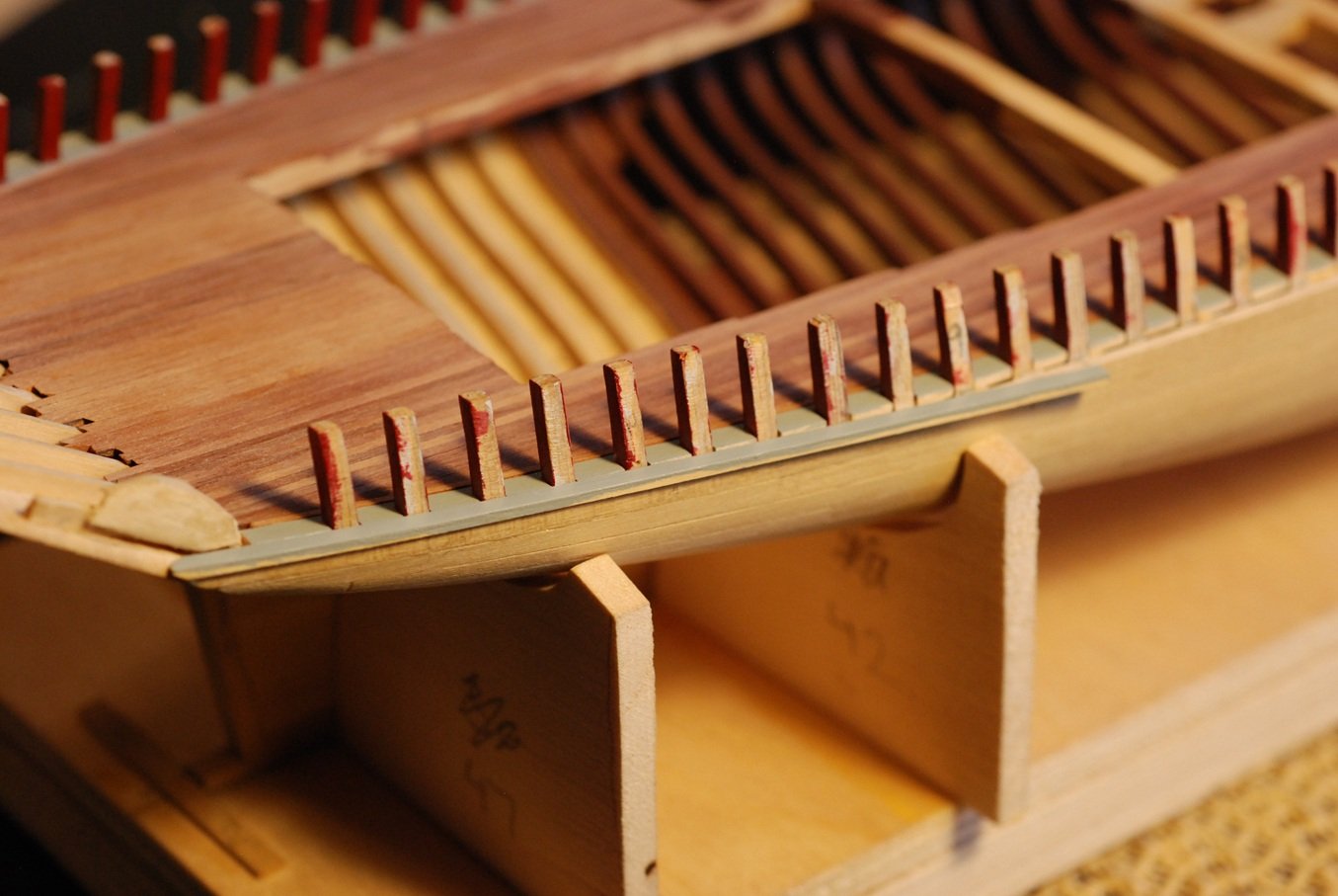
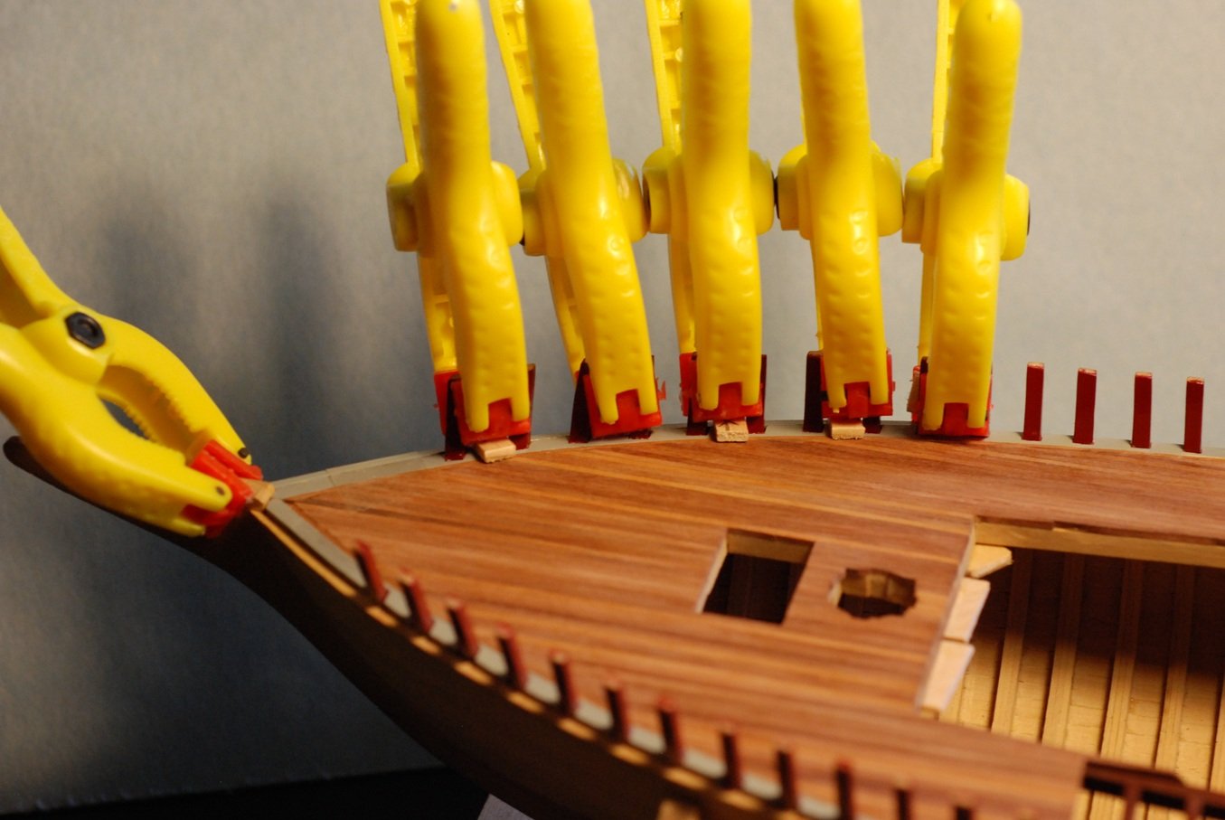
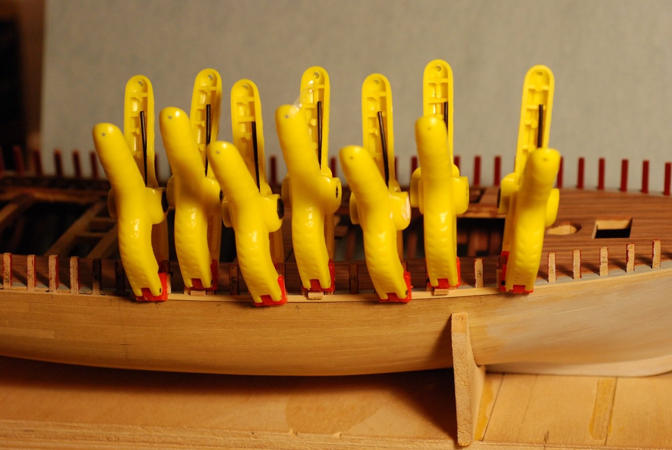
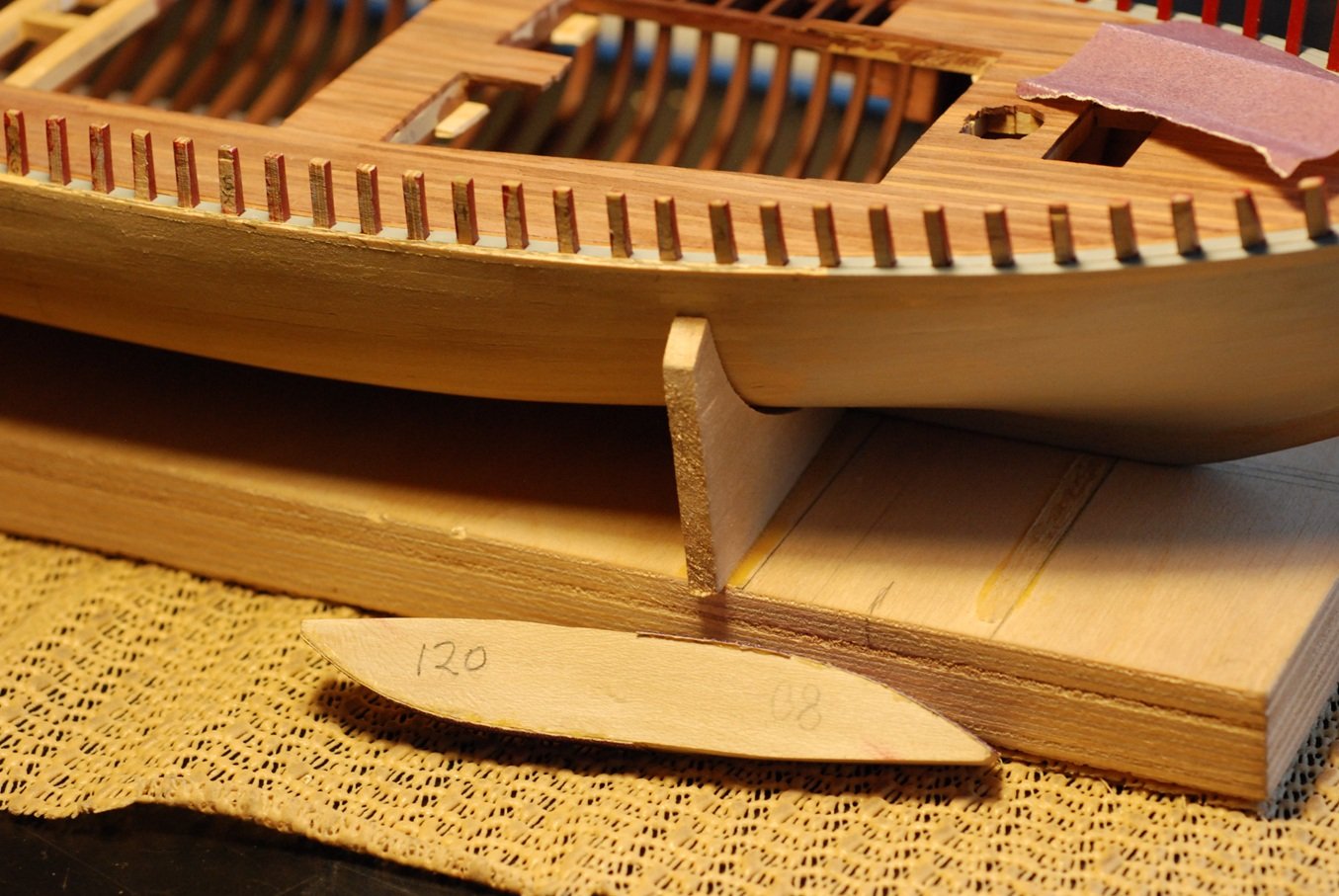
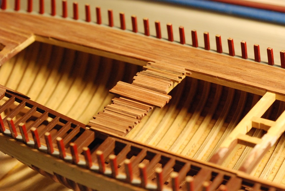
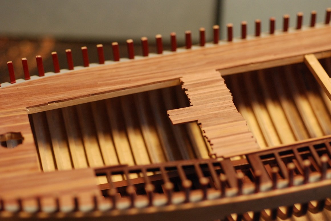
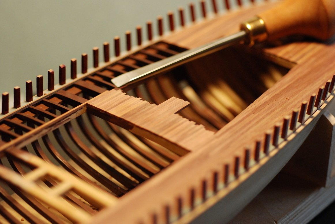
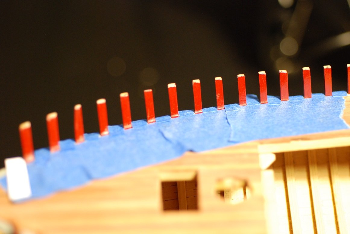
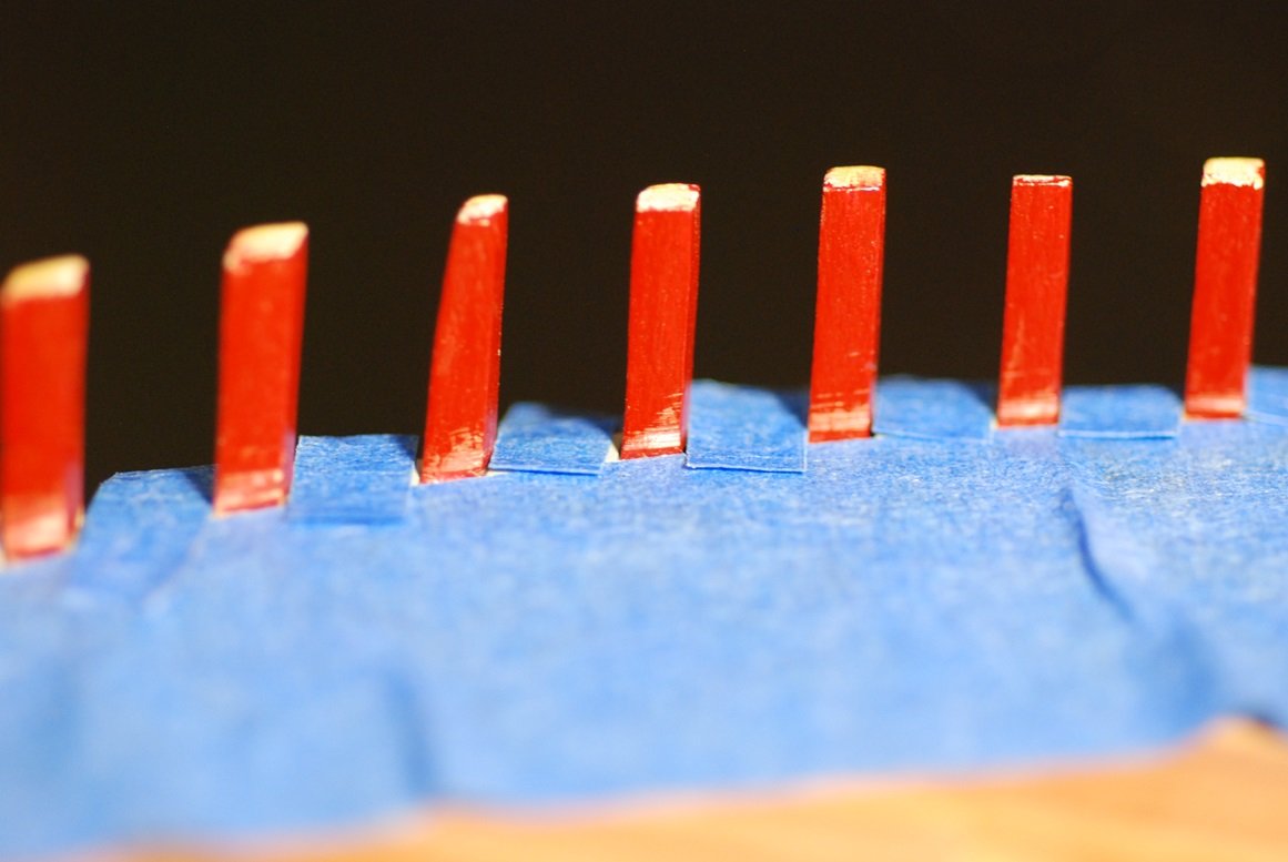
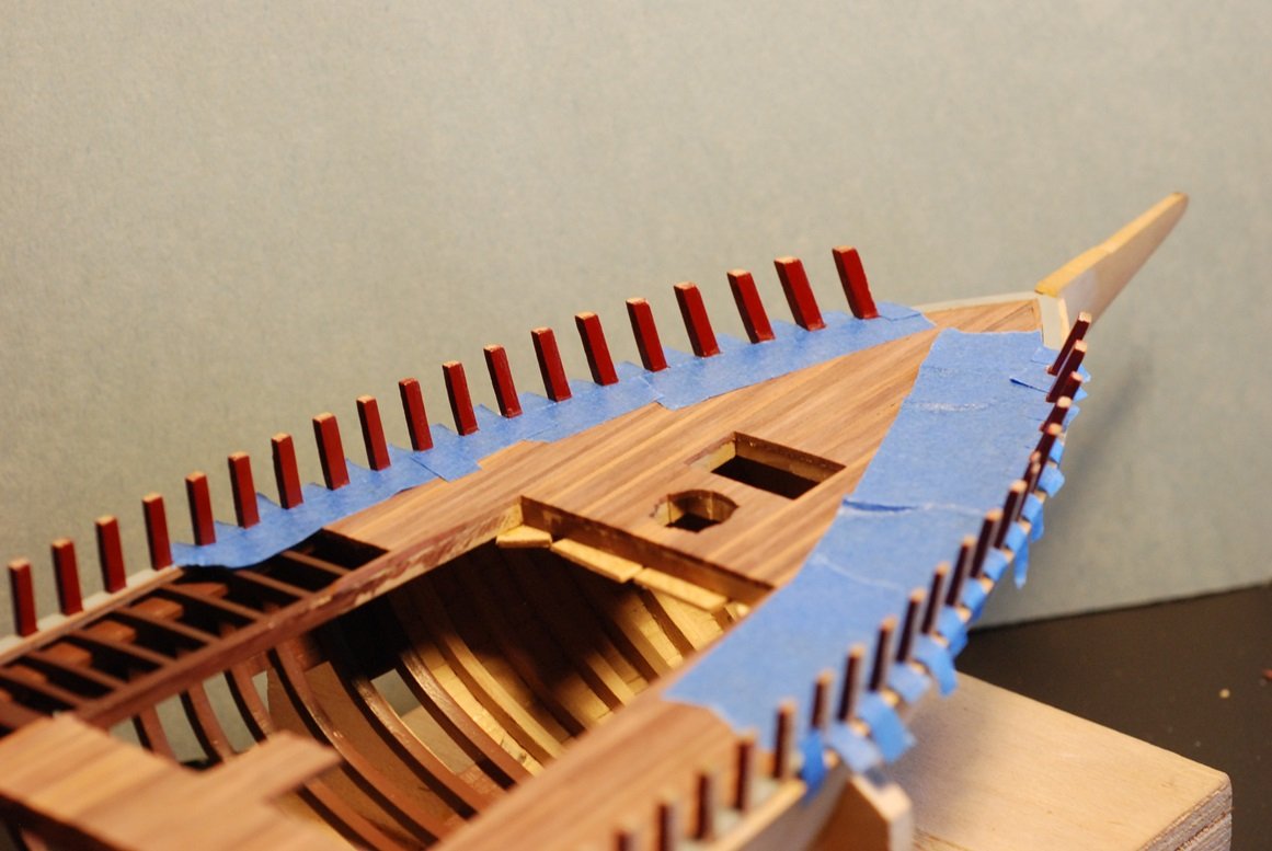
When repeatedly test fitting these pieces, care had to be taken in order to maintain consistent placement of the two articulating planks against their stanchions. For this reason, I drilled a couple of holes in the aft plank and its underlying stanchion, large enough to accommodate a T-pin. One was also placed in the forward plank. These ensured that the planks were landing against the stanchions the same way every time. The forward end of the forward plank was shaped to meet the filler block. But besides the filler block, this end of the plank currently has nothing to land against. So, it’s time to model the visible portion of the knightheads, the solid gray pieces of wood on either side of the bowsprit. The hawsepipes for the anchor chain travel through these pieces. It’s worth noting that this picture exemplifies a difference between my model as built to the original builder’s plans and how it exists today. During the refit in 1999-2000, additional stanchions were added toward the bow that were not part of the original design. Those stanchions are visible in this photo but are absent from my model. The knighthead pieces were built up from a couple of pieces of scrap, and their surfaces sanded down to accommodate their angle against the deck and the area of the bowsprit. There is a small hole for the anticipated location of the hawsepipe where it emerges from the planking, previously estimated by eye. However, this photo from 2024 suggests that my initial attempt is located too far aft. So the position was adjusted and marked with a pencil mark. Then the old hole was filled with a dowel and cut smooth, then painted over. I placed a small pin in the bottom surface of the knighthead and drilled a corresponding hole in the underlying covering board, to give it some strength. Now it is fitted in place. This piece will be trimmed down in the future to accommodate the width of the 8-inch-wide bowsprit. The beginnings of a hawsepipe have been started in it; the hawsepipe will not be brought to its outer surface until the overlying planking is installed. Now it’s time to dry fit the first of the four bulwark planks, again ensuring that there is no gap between it and the covering board, but also ensuring that the plank is pressed up against the stanchions. I made these little things to sit on top of the plank so that a clamp could push against them and the underlying plank, forcing the plank down against the covering board. After a lot of dry fitting, and after purchasing many more clamps, the glue-up was performed and left to dry overnight. But first I attempted to reach any squeeze-out of glue between the clamps that would be visible inboard. Here is the next morning, with the clamps removed and showing the various support pieces of scrap that enabled a proper grip of the clamps on the plank. The scrap pieces on the stanchions ensured that the grip of the clamps on the plank was directly inboard and not on an angle. Voila!! No gaps! There are some areas on the inboard surface of the plank that will require some touch-up painting, but the overall result is really nice. These pictures remind me to say that the inboard surface of the plank was pre-painted, and any paint drifting into the areas where the plank meets a stanchion had to be scraped away before applying glue. Here I am dry-fitting the forward plank; I have not yet glued this one in place. Let’s have another look at that scarf joint area! (This one is actually for the opposite, port, side.) Very pleased with how that looks. So, once the remaining 3 planks are installed, then planking of the rest of the bulwarks should go pretty quickly, followed by installation of the rail. At the same time, I am working on marking out the waterline, plus I am continuing to work on the miniature carving of the trailboard. So much to do!
-
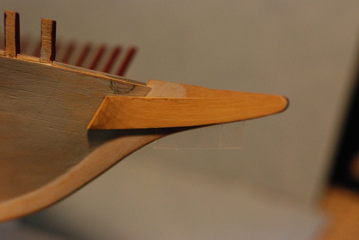
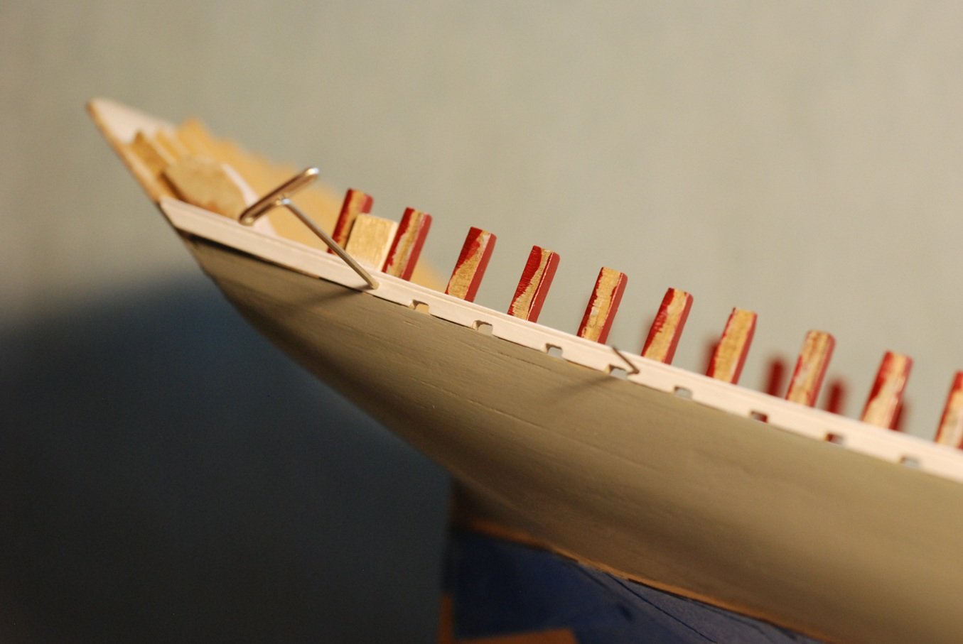
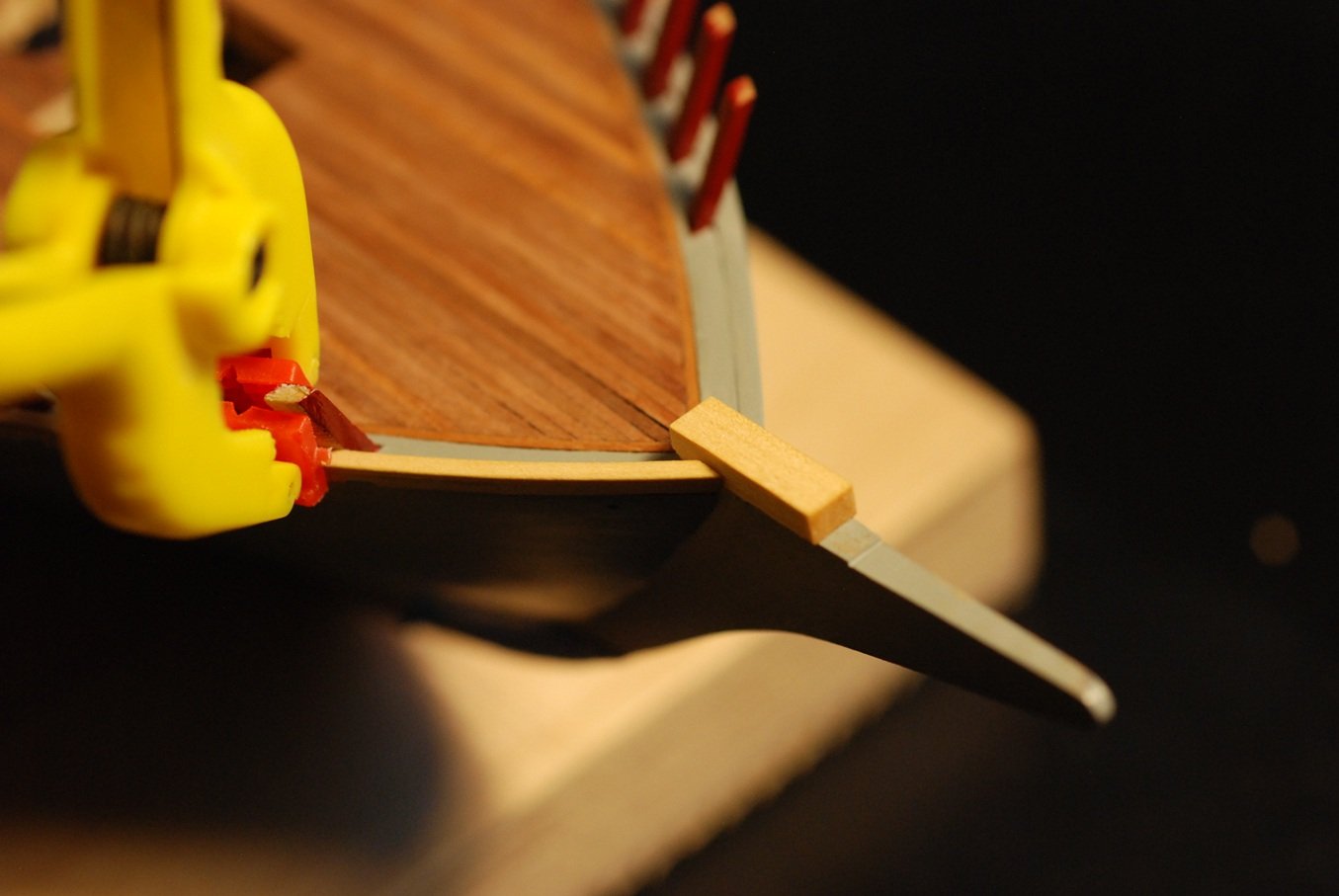
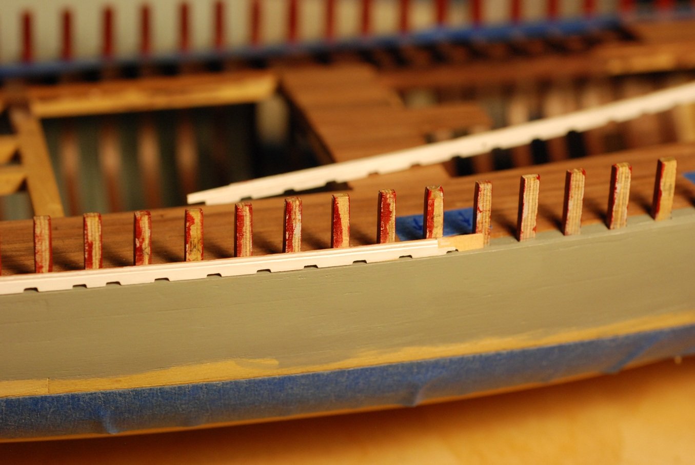
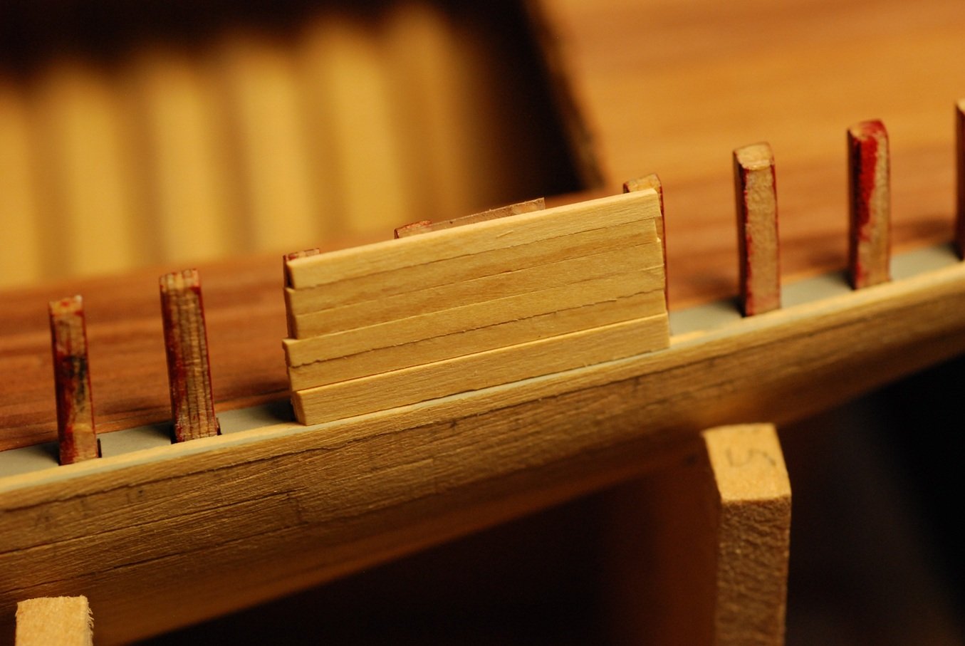
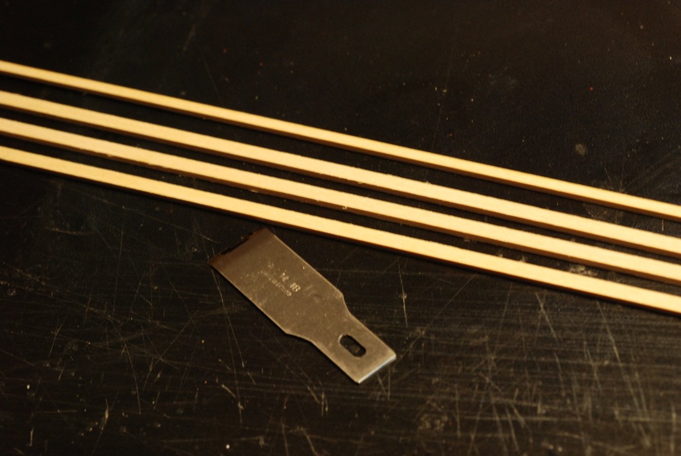
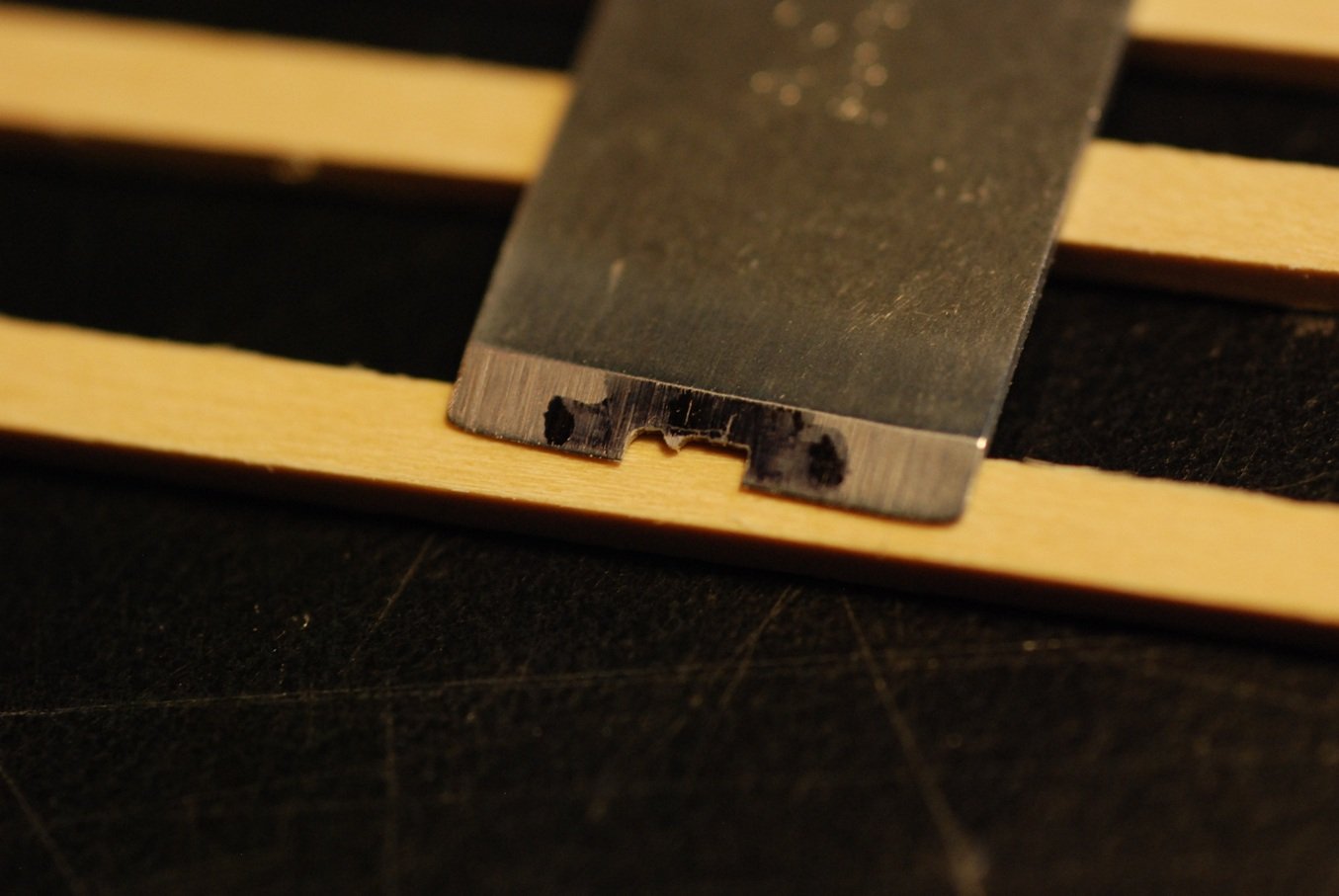
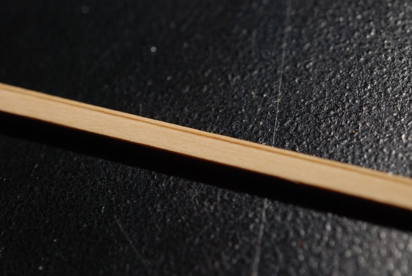
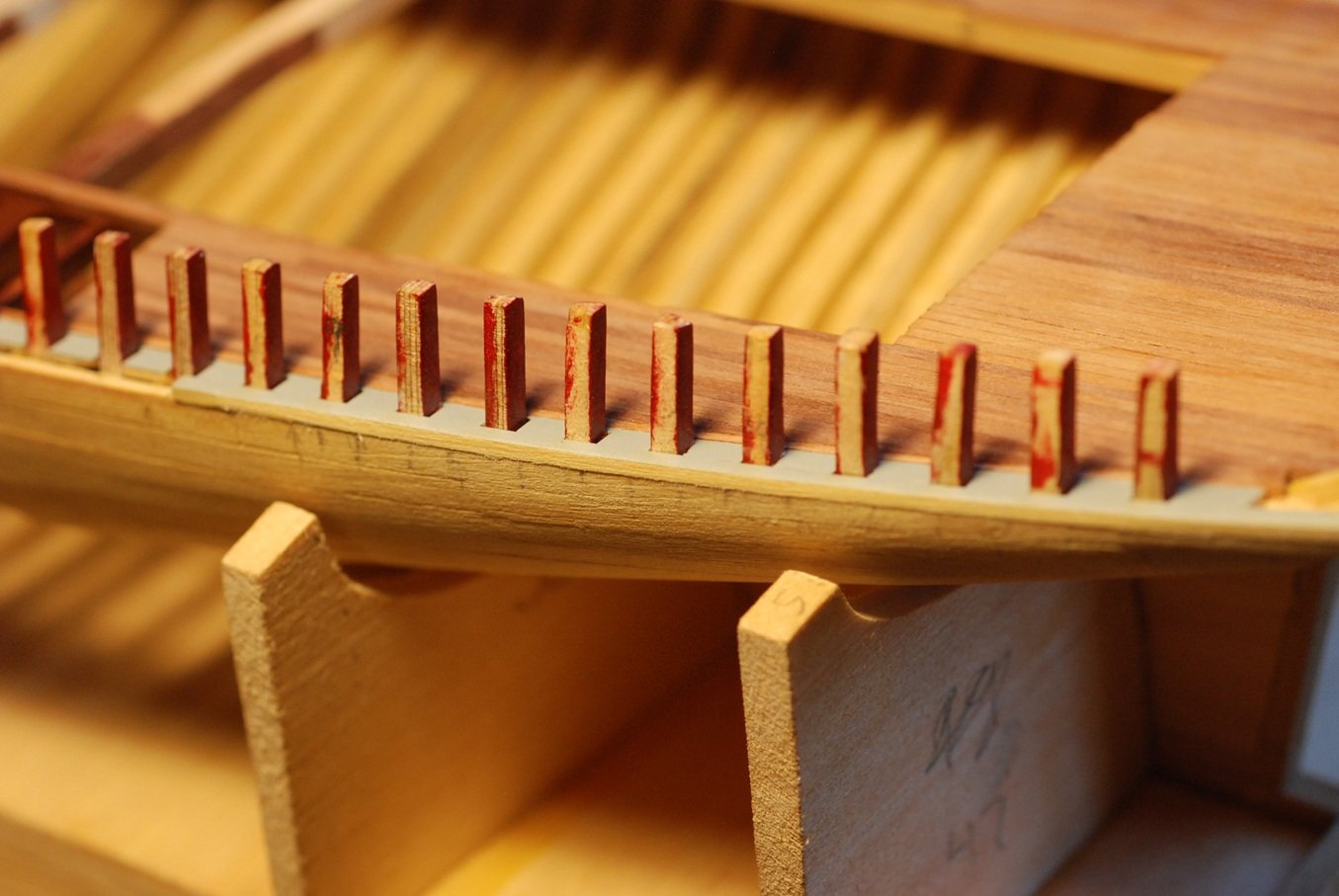
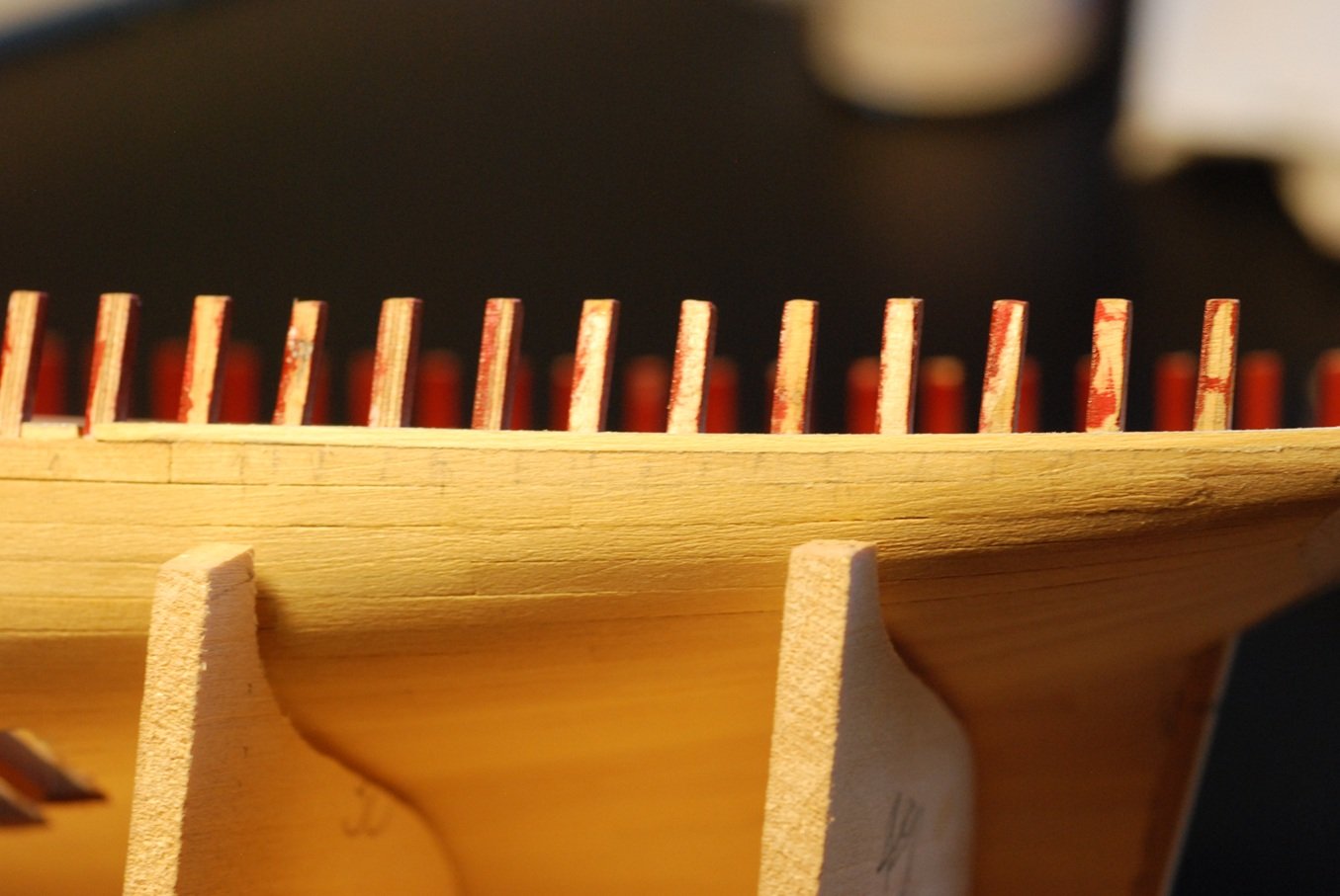
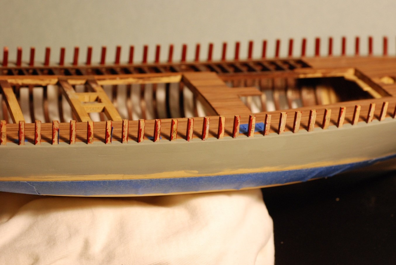
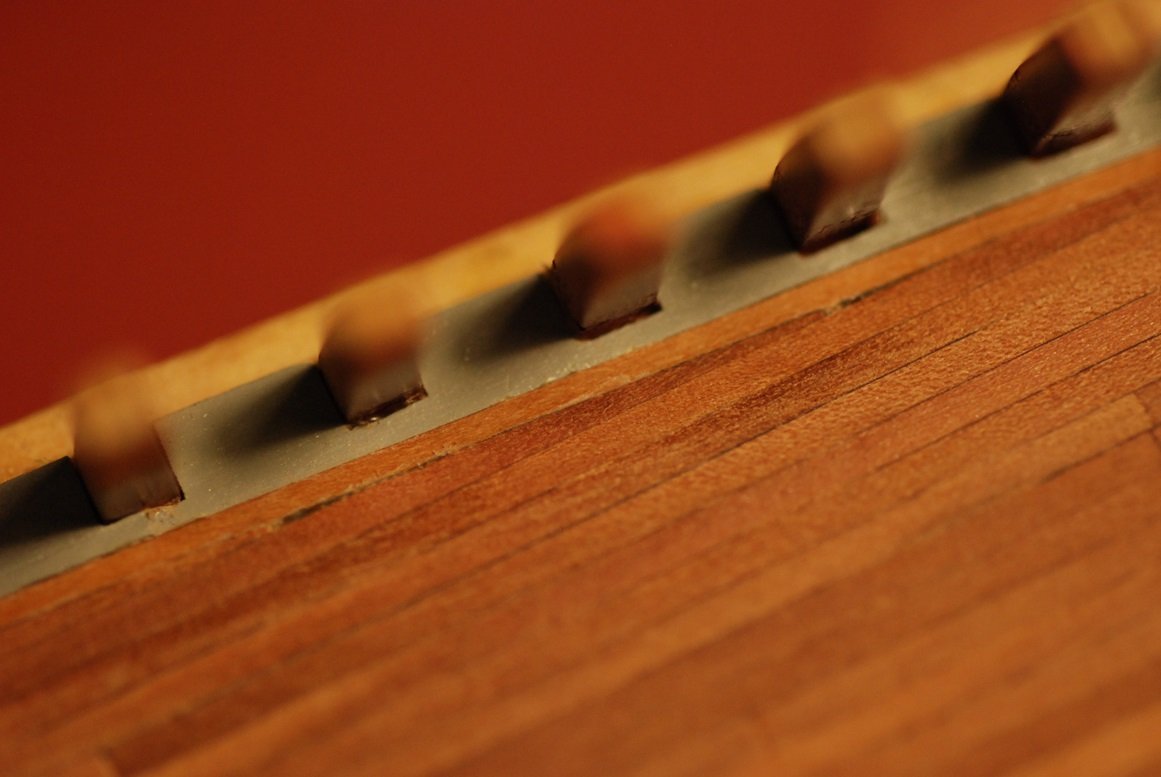
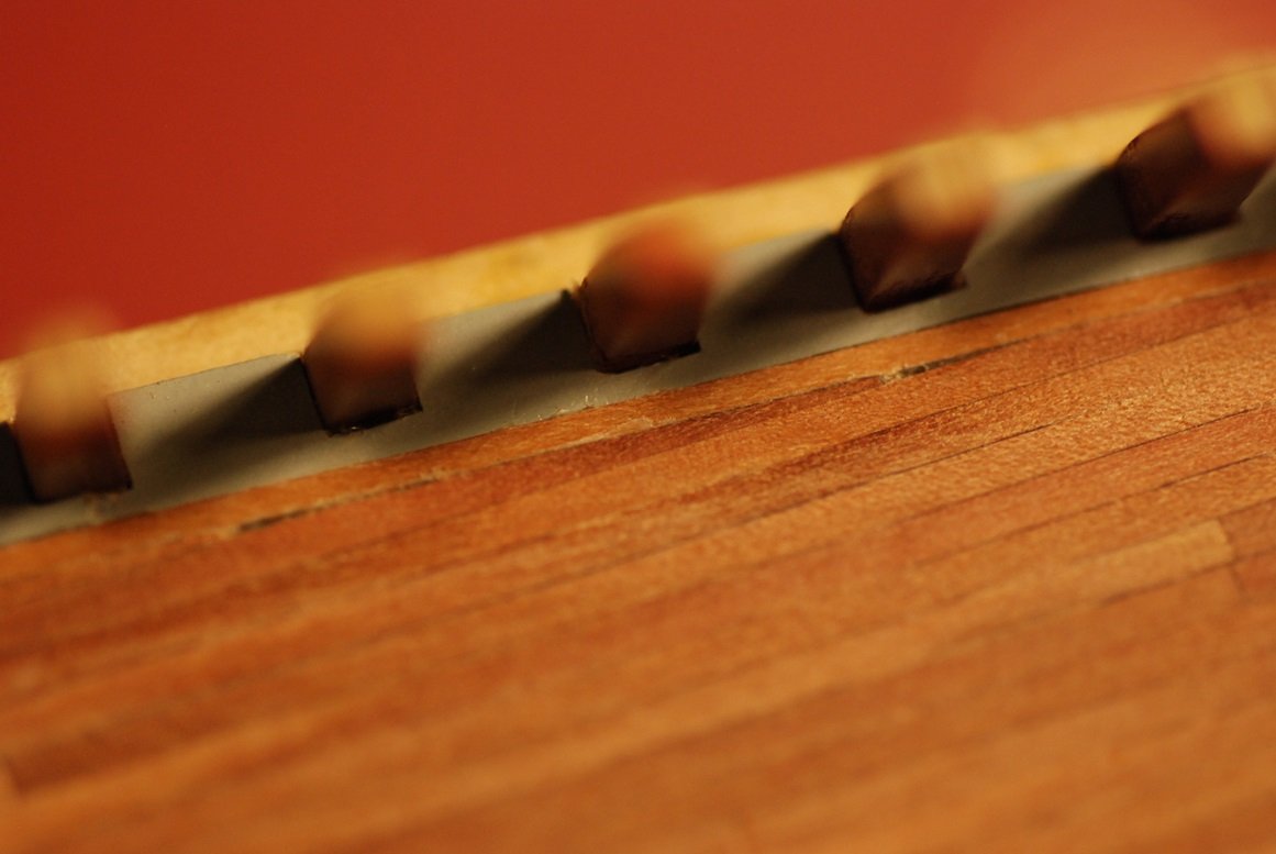
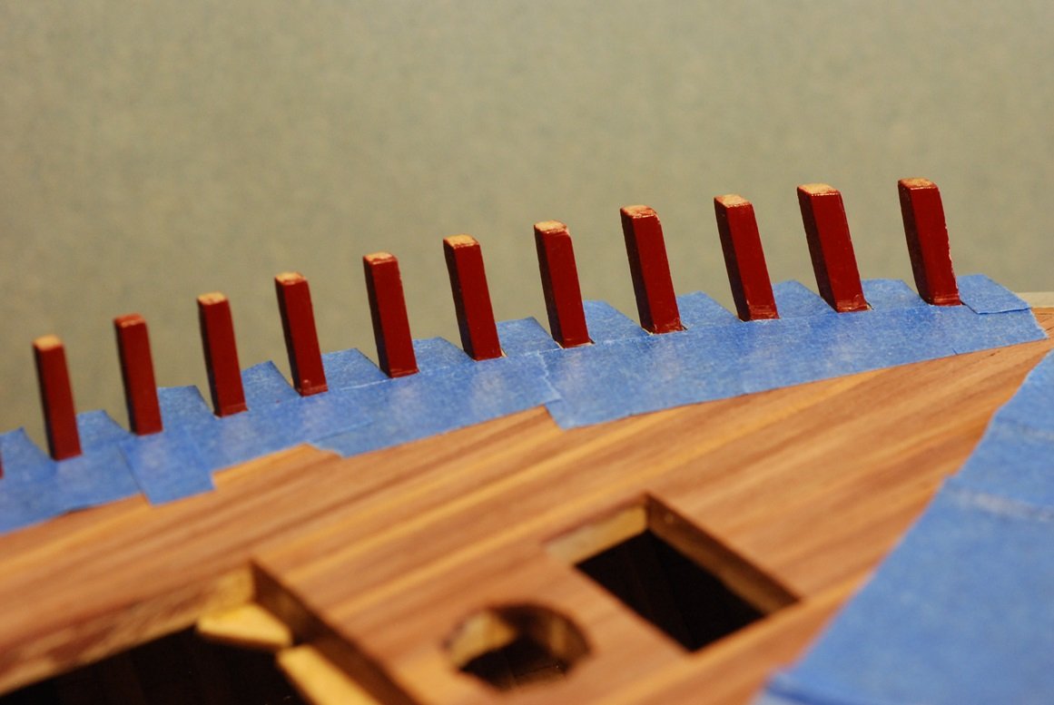
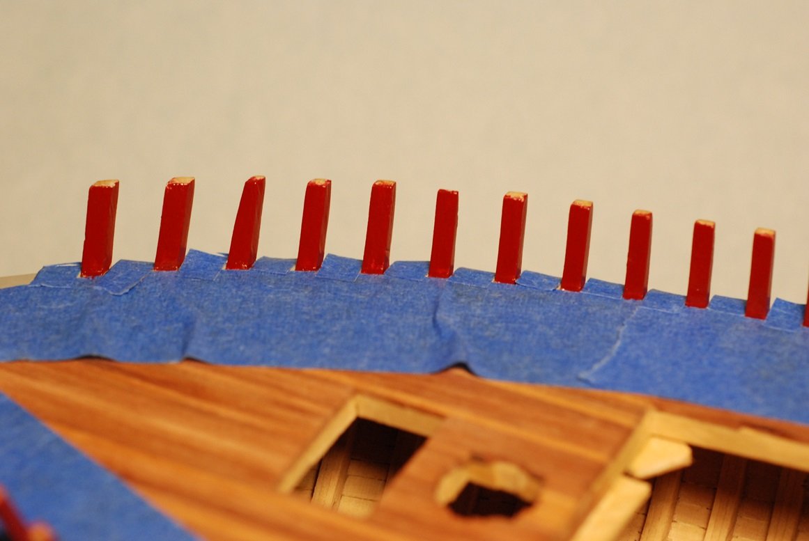
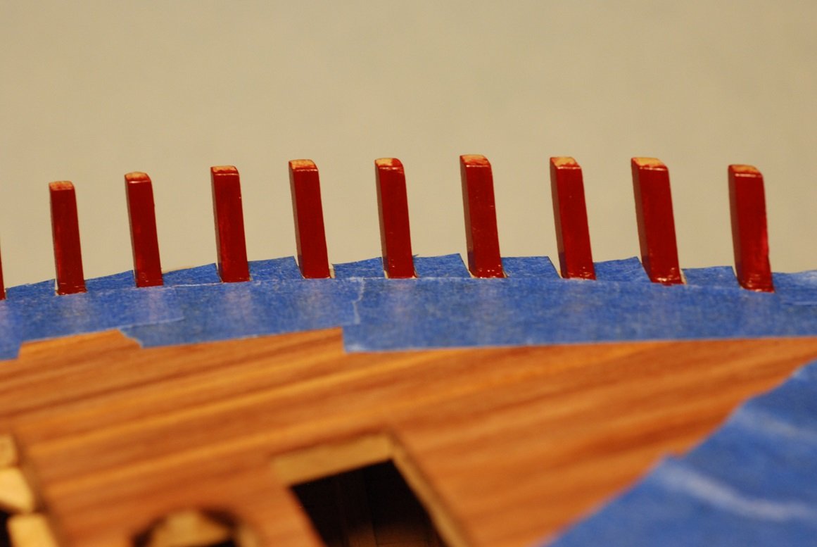
So, now on to the first bulwark plank. In this picture, I am mocking up how many planks there will be in order to get to the undersurface of the rail. The first plank is slightly thicker than the rest, and again it will feature that bead that is visible in the initial picture above. Next step is to create the bead in the top edge of the first bulwark plank. This required me to learn about how to make a scraper. There will be four strips of wood for modeling this plank, 2 on each side with a scarf joint at midships. I used a cutoff wheel on a Dremel to carefully cut into the edge of this X-Acto blade. I found that the gap between the top edge (on the left) and the barb of metal adjacent to it was too small to accurately cut using the cutoff wheel. The solution was to make the strips overly wide, then scrape in the bead feature, then run the strips through the thickness sander while tilted up on their edges. In this way, I could end up with planks of the right width, with the bead feature right at the top edge and in scale with the actual appearance. I had these great pictures taken through the microscope showing some of the process of cutting in the scuppers, but MSW has decided not to accept those pictures! Oh well. This picture shows that the first plank needs to be steam bent to accommodate the curve of the hull, of course along its thin dimension, but also including edge setting. This is particularly necessary in the bow, where the hull has a degree of “powderhorn” that leads to the first plank initially curving upward, but then curving in a downward direction as it approaches its end at the bowsprit. The powderhorn is accentuated in this picture. The plank ends against a temporary spacer applied to the stem, which corresponds to the width of a support block located below the bowsprit. The bowsprit itself will be much wider than this spacer. Here we have one of the aft planks, with its scuppers cut into it. Placement had to be precise due to the location of the scuppers as well as where the aft end of the plank meets the transom planking. In addition, the bottom edge of this plank had to be shaped so that it cleanly met the level surface of the covering board, accounting for how great or little the underlying stanchions leaned in comparison to the covering board. This picture illustrates that simply placing a clamp on the plank leads to a gap at its lower edge, in part due to the force placed on the upper edge of the plank by the clamp, but also due to the shape of its bottom edge. Shown here is the scarf joint and its placement relative to the underlying stanchions, as well as some gapping between the covering board and the plank. Here I am beginning to work the other side of the scarf joint into the forward plank. It’s always satisfying to see a scarf joint come together! And this one has the added complexity of a scupper within it, as will the joint on the port side. This shows how the scupper is worked into the joint. More posts will follow shortly...
-
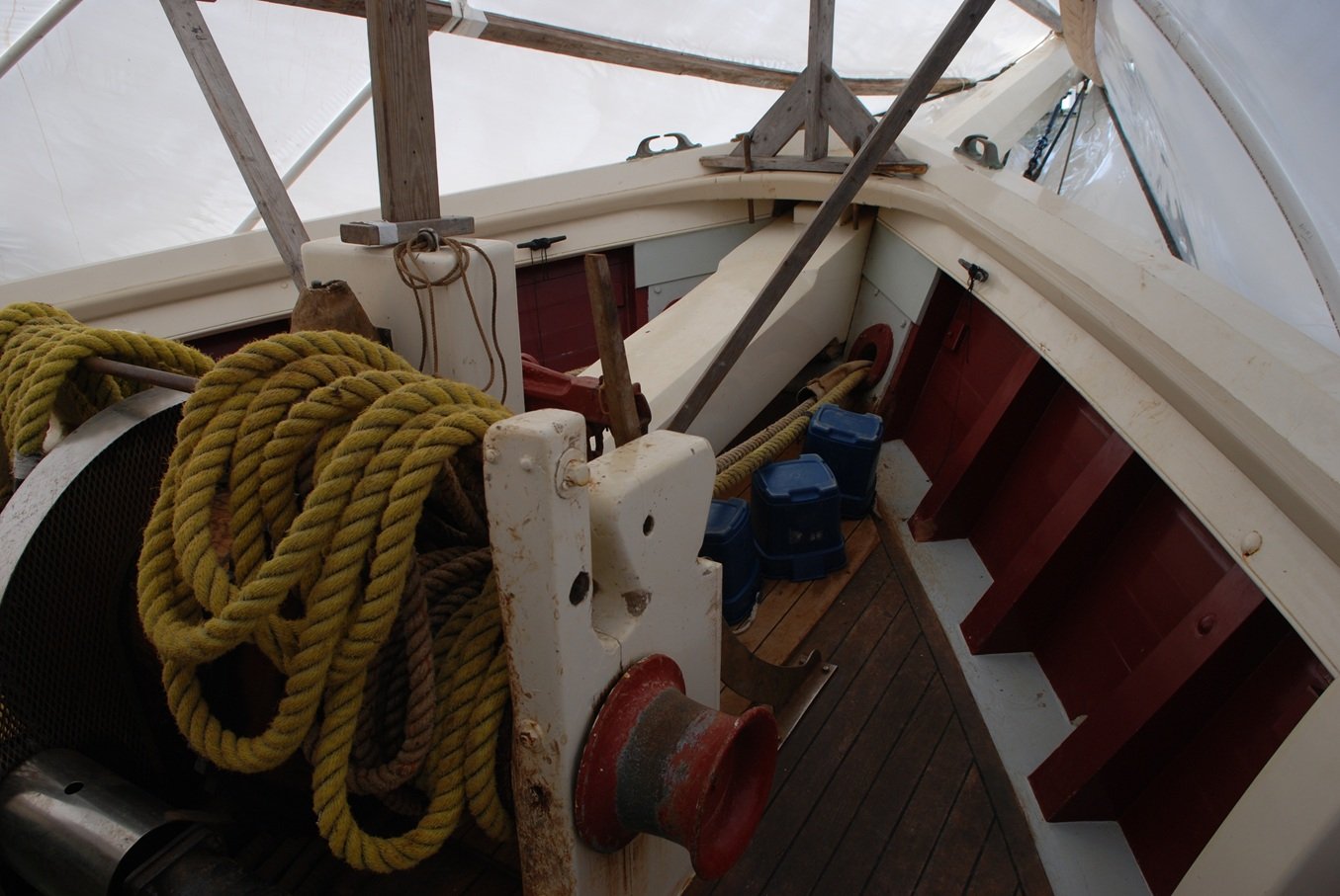
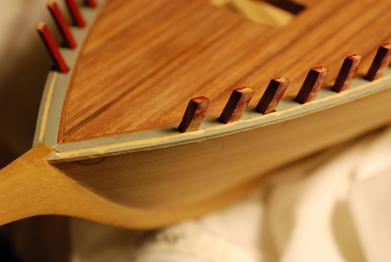
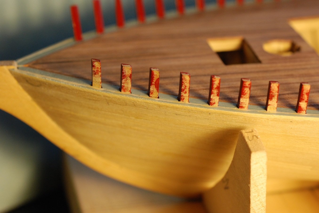
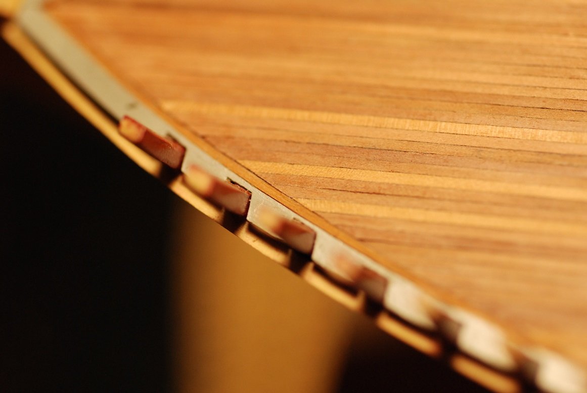
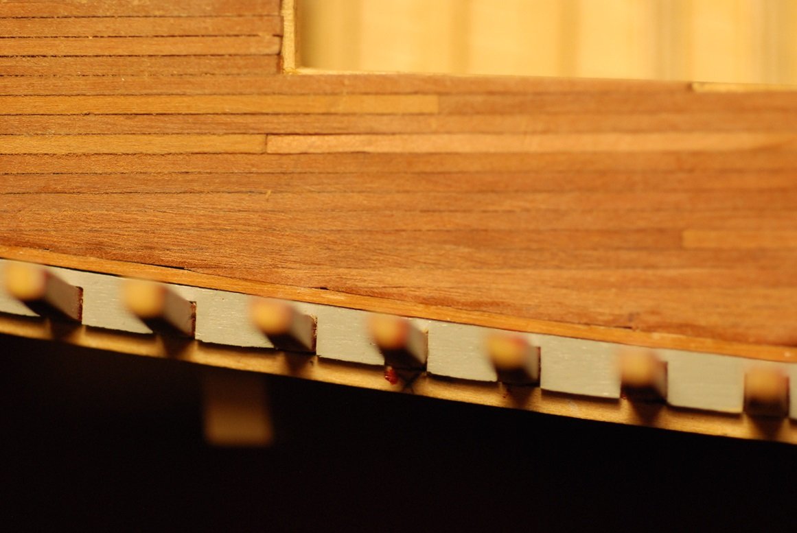
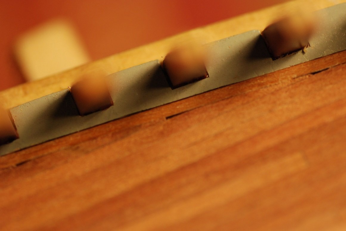
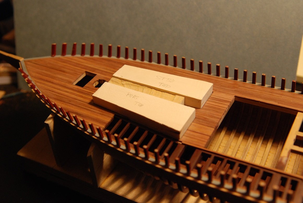
Things are really starting to get interesting on the Mary Day hull! This photo was taken this past summer while on a trip with friends on the Mary Day. The picture shows the next area of interest, as I will finish off the covering boards by applying a strip to their outboard edge, then manufacturing and installing the first bulwark plank. The picture shows that there are numerous scuppers along the entire length of the first plank. There is also a bead detail at the top edge of the first plank that will be modeled. The interface between the covering board and the first bulwark plank is a critical joint in the appearance of the model and it will take some work to accomplish. After that, installation of the remainder of the bulwark planking should be much simpler. I will break this part down into a few posts. The covering boards are 3 inches in thickness, so the lower of these 2 pieces is ideally 3/64” thick. These are test pieces in order to make sure that things look proportional before cutting out the full length pieces. The width of the lower piece is arbitrary, as it will be cut and sanded smooth with the surface of the hull planking below it. That is shown here. In order to not have to deal with bending this piece in the bow area, I cut strips corresponding to the curve of the bow. This was not so necessary in the remainder of the hull, especially toward the stern. The top surface of the hull planking just below the covering board had a varying angle, so that in some areas this strip of the covering board would be canted inward, in some areas it was level, and in yet other areas it tilted outboard. It was very important to have this joint look clean and tight. Gluing down this strip in the bow area required clamps that compressed the strip in an inboard direction, but also some clamps that would force the strip downward against the hull planking. The clamps with wood pieces beneath their jaws are exerting downward pressure. How it looks from outboard. In the bow area, the top surface of the hull planking is canted in an outboard direction, so the strip in this area is thicker than in others. That meant that the inboard edge of the strip had to be slightly thicker than elsewhere, and its surface trimmed down level with the remainder of the covering board, in order to end up with a level surface. And then the width of the strip could then be cut and sanded smooth with the contour of the hull planking. This is my sanding board created for that task. Here are a couple of pictures showing the end result, after everything is trimmed level and painted up. Next post we will start into the bulwarks planking.
-
Mike, perhaps you are one of those aliens that has multiple appendages from the Men In Black series of movies?
- 969 replies
-
- 1
-

-
- hahn
- oliver cromwell
- (and 1 more)
-
I am going to be referencing this build log for many years to come! Thanks Johann for all these clever rigging insights!
-
It is good to hear that they were responsive to your request, Johann!
-
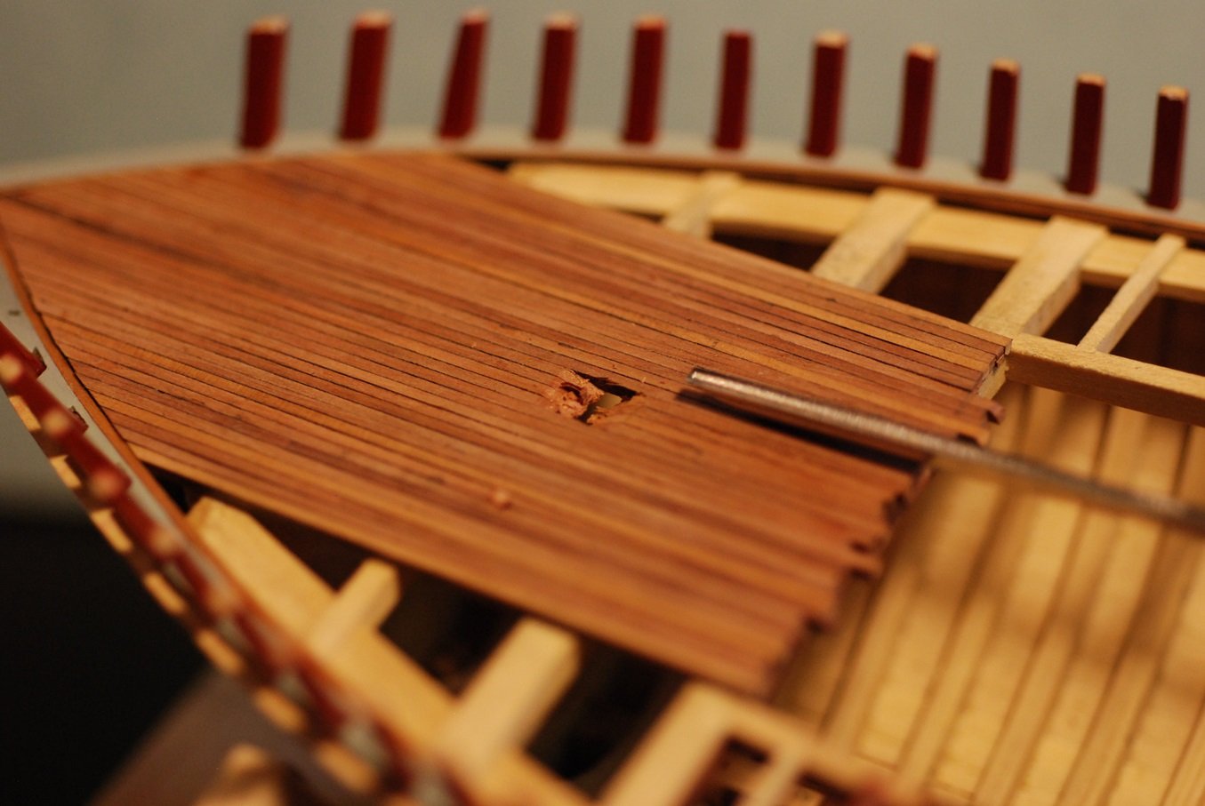
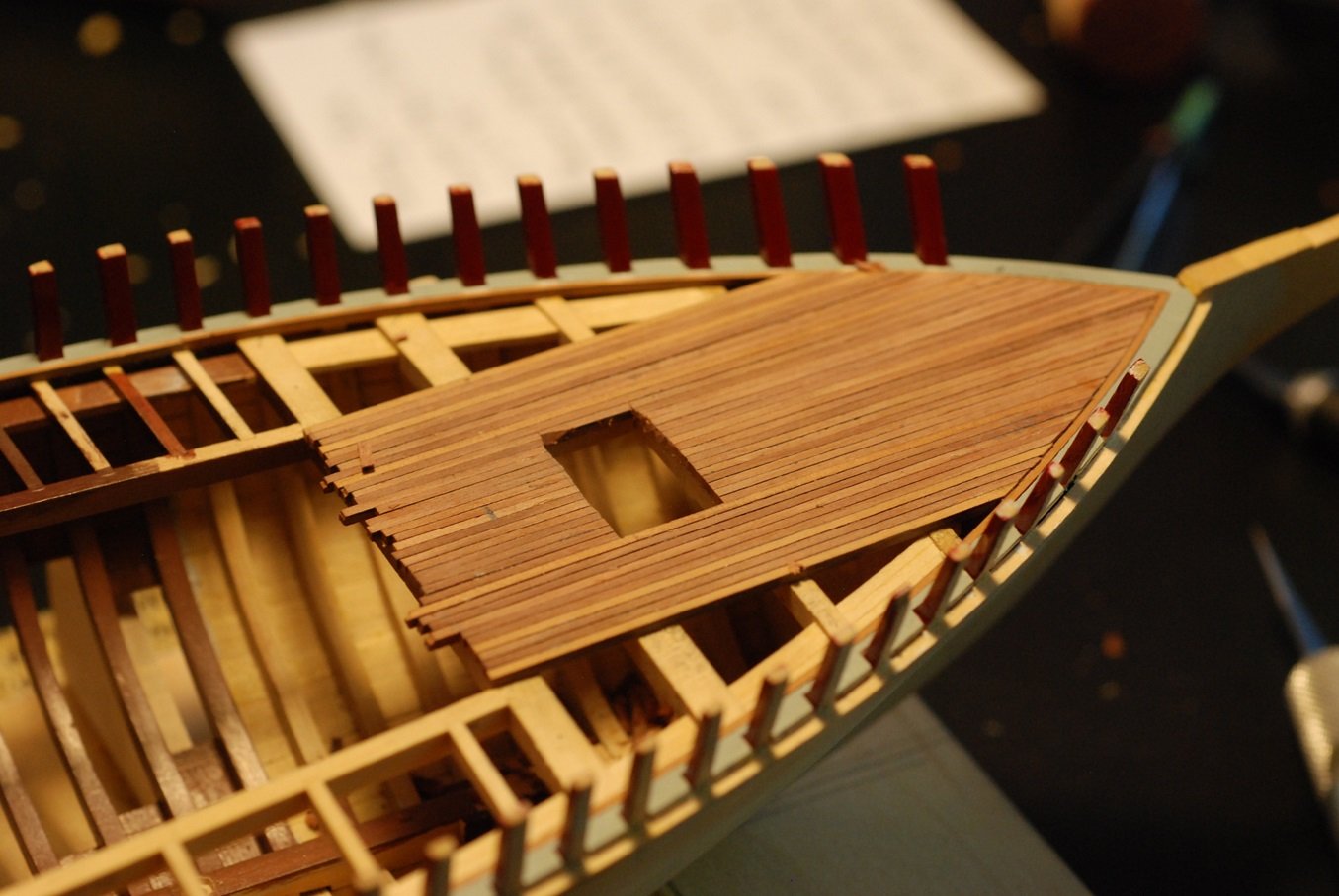
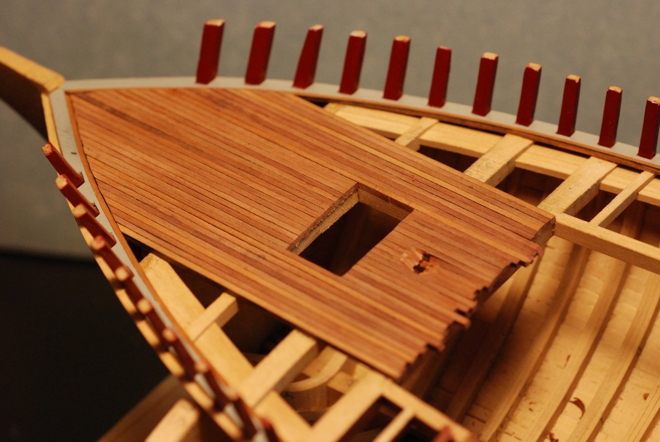
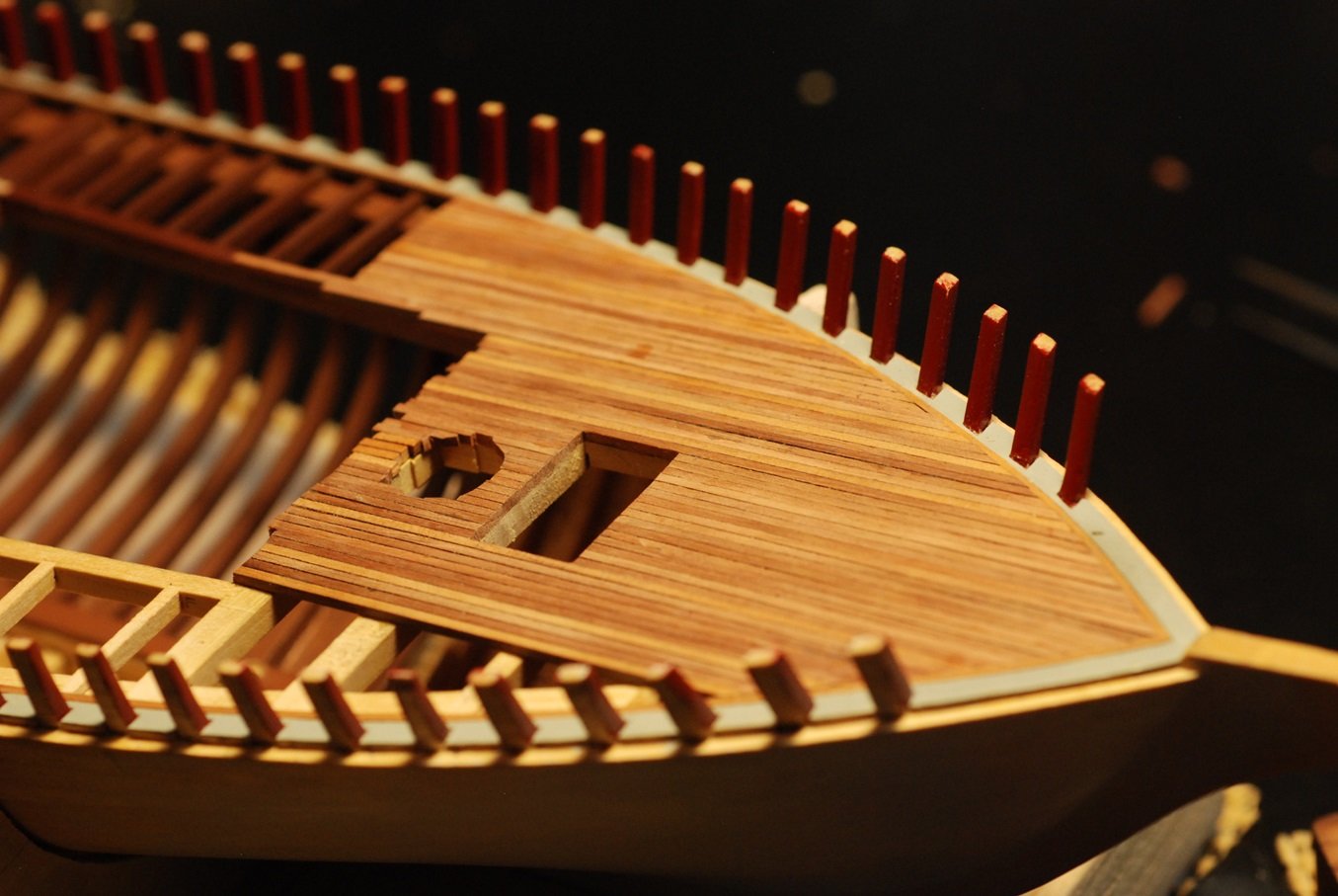
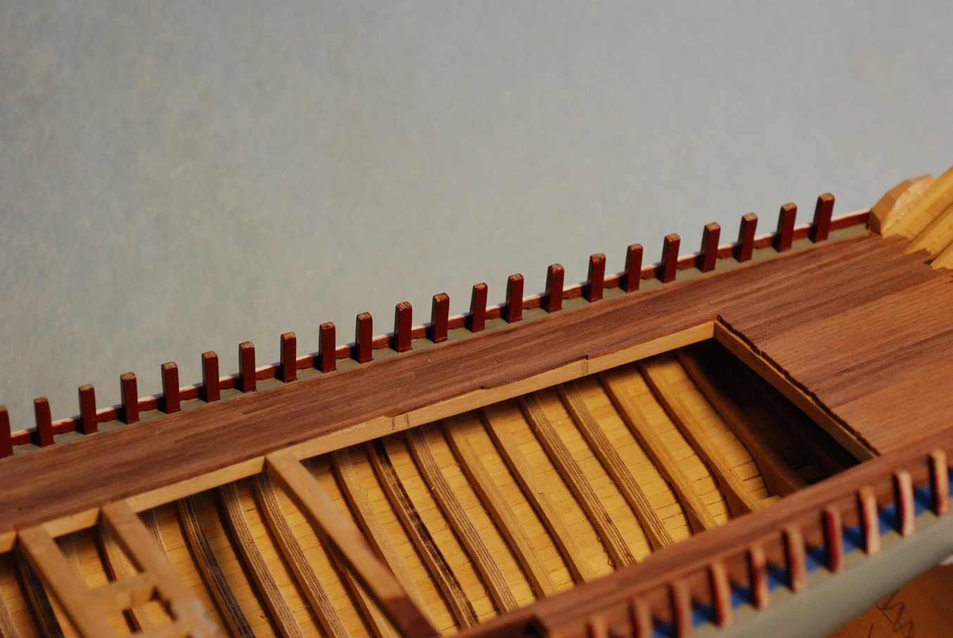
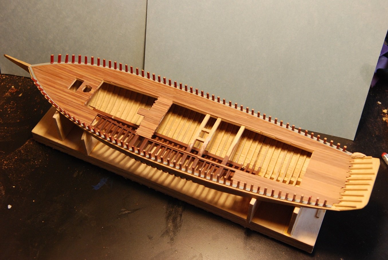
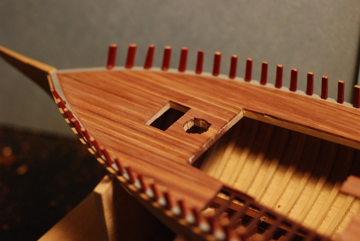
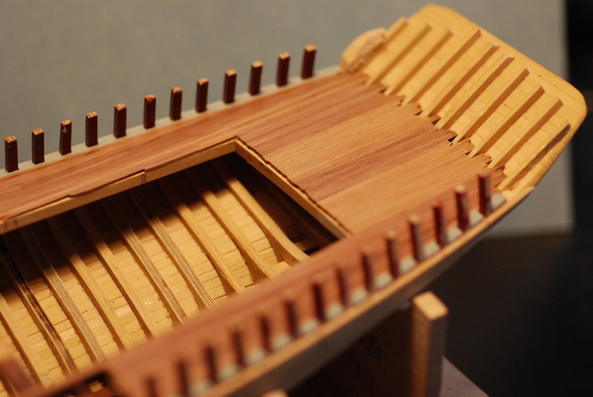
Since the last post, the deck planking has been finished. Here are some overviews of how things look. The open areas along the centerline will be covered by cabinhouses. Plus an opening for the foremast and the foc's'le hatch. The aft end of the planking will be covered by the lazarette. Details of this process included leveling of the interface between the deck planking and the margin plank. There is a little stepoff in this area. Here this has been cleaned up. Another detail includes little gaps where some of the planks terminate in a fine point. These areas were filled with wood glue. Then the excess was scraped away. Still a little gap, but at distance it looks very clean. Not detailed in these pictures is the process of first sanding the deck planking with sandpaper up to 220 grit, then scraping the deck with the edge of a scalpel. After doing so, the deck feels wonderfully smooth! The area between the fore and main cabinhouses needed planking, which includes an area of planking that extends forward in the area of the companionway for the fore cabinhouse. Here the planking has been put in place. Then the edges were pared off using this very sharp chisel. One consequence of the finshing process for the deck is scrape marks on the paint on the bulwark stanchions. Fortunately this was really only present in the bow area. Everything is masked off, ready for touch up painting. After several coats, things are looking better. Here is a preview of upcoming work, in which I am working on a form that will be used to construct the fore cabinhouse. I don't plan on making this from a solid block of wood, but rather 3/64" thickness sheets. I also need to do touch up painting of the exposed deck framing. More to come!
-
Thank you Mark, I will hit the "Mark" as solution button in your honor! JD
-
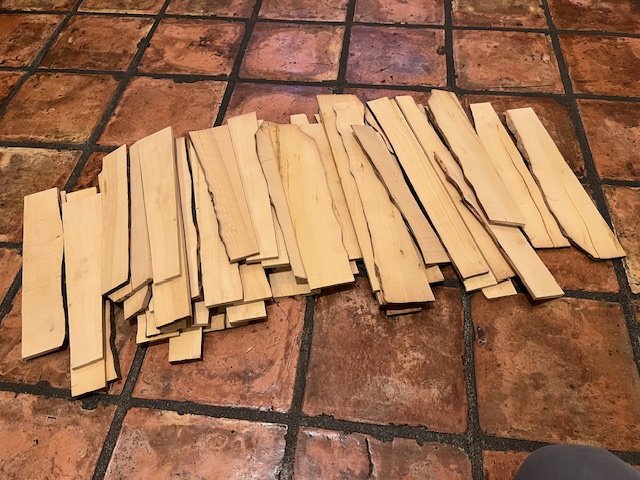
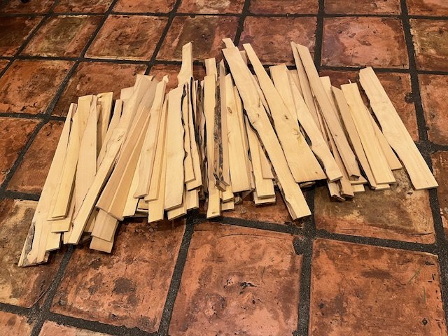
Attached are pictures of 2 batches of about 10 pounds of boxwood (Buxus sempervirens) that was milled in quartersawn fashion from larger pieces I obtained about 5 years ago. One picture shows sheets that are about 2" in width. They range in thickness but are around 1/4" in thickness (no thicker). They do contain various imperfections but there is lots of usable straight grain wood. Length range is 12-18". The other picture from the same batch shows additional sheets that are 1/4" in thickness but not as wide as these, averaging 1"-1.5". This is again a batch weighing about 10 lb, again with various imperfections but plenty of usable straight grain wood. In the case of either batch, there is plenty of wood for working out frames for your admiralty-style model. Let me know if you are interested, and we can start a conversation offline!
-
Oh, I also created apertures in the foredeck for the foremast and the foc's'le hatch.