HOLIDAY DONATION DRIVE - SUPPORT MSW - DO YOUR PART TO KEEP THIS GREAT FORUM GOING! (Only 13 donations so far - C'mon guys!)
×


jdbondy
-
Posts
340 -
Joined
-
Last visited
Content Type
Profiles
Forums
Gallery
Events
Everything posted by jdbondy
-
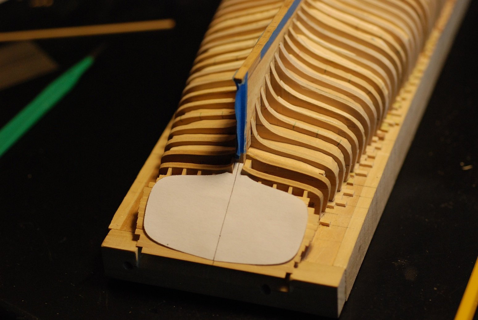
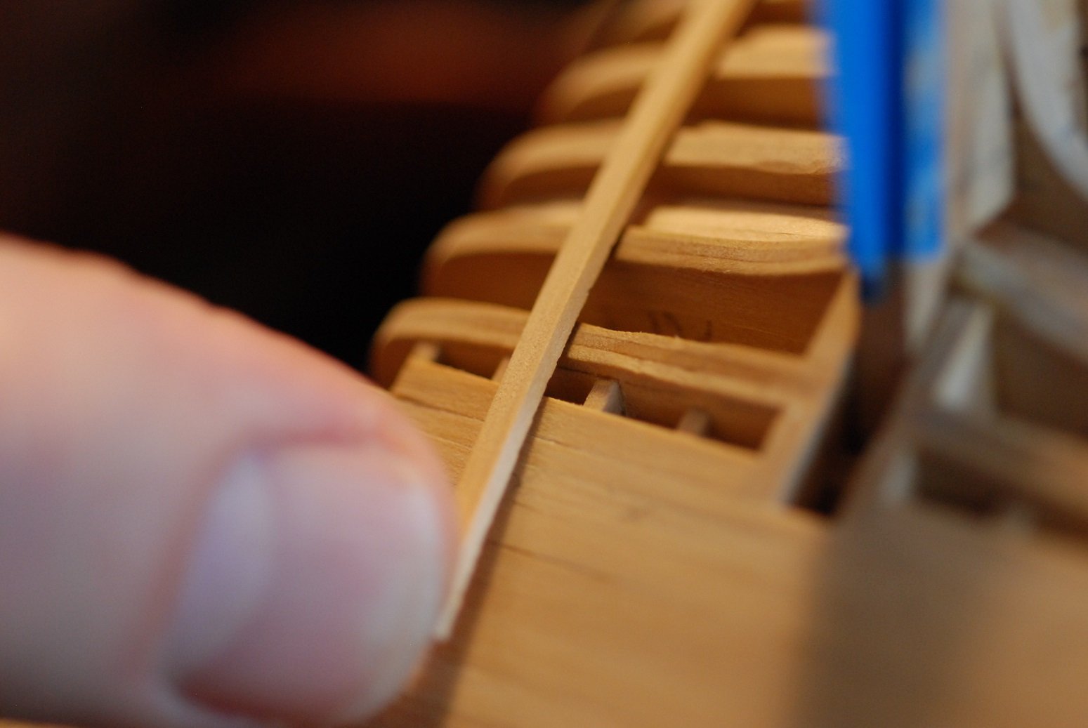
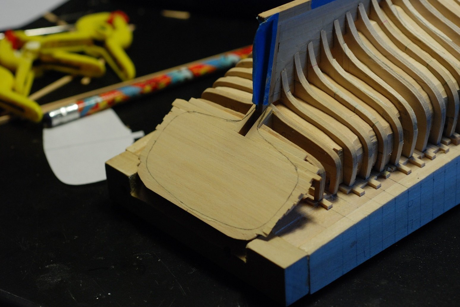
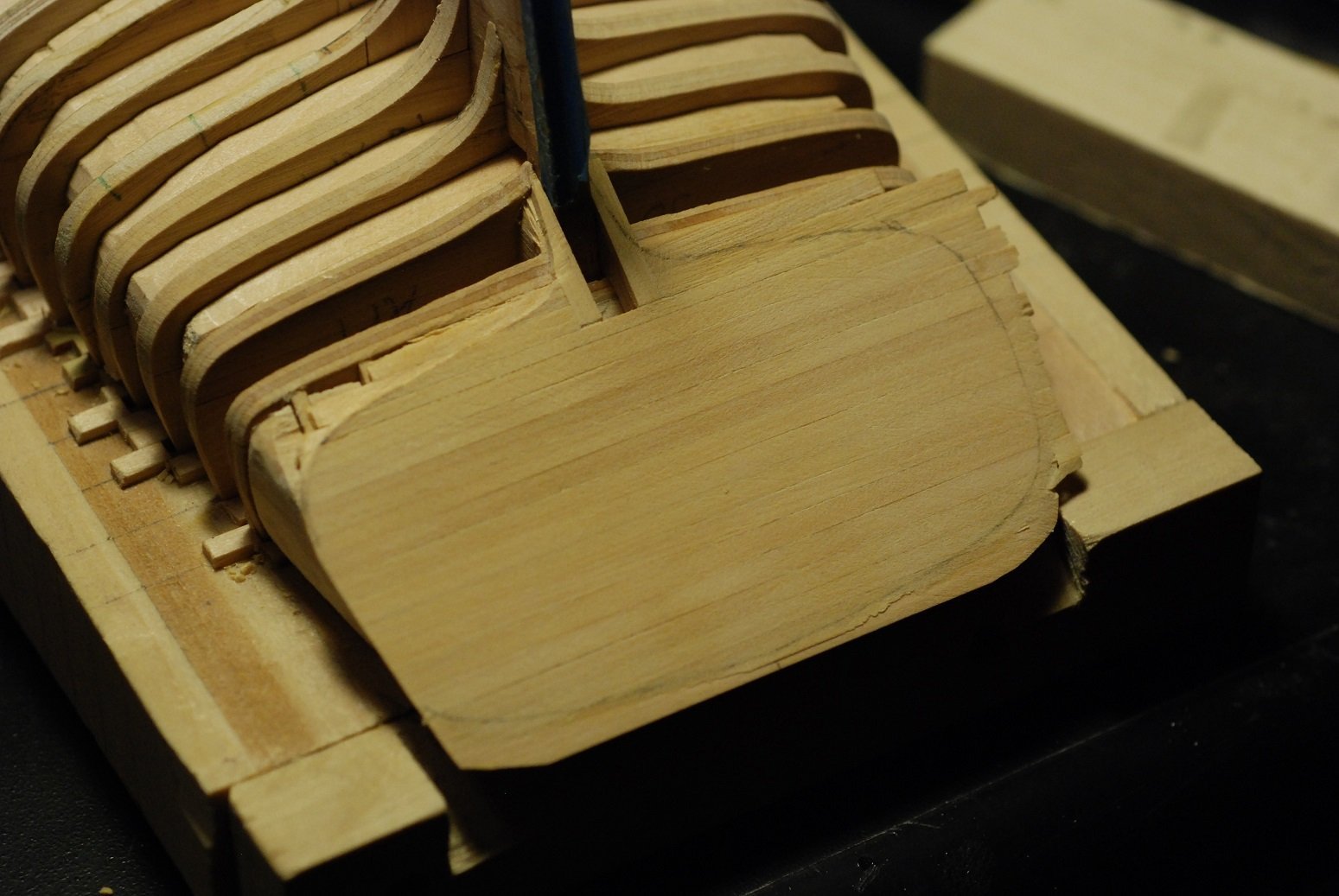
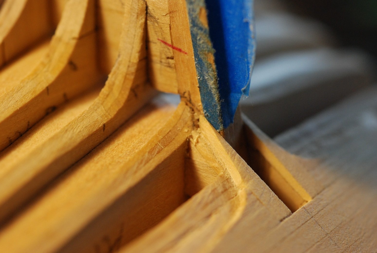
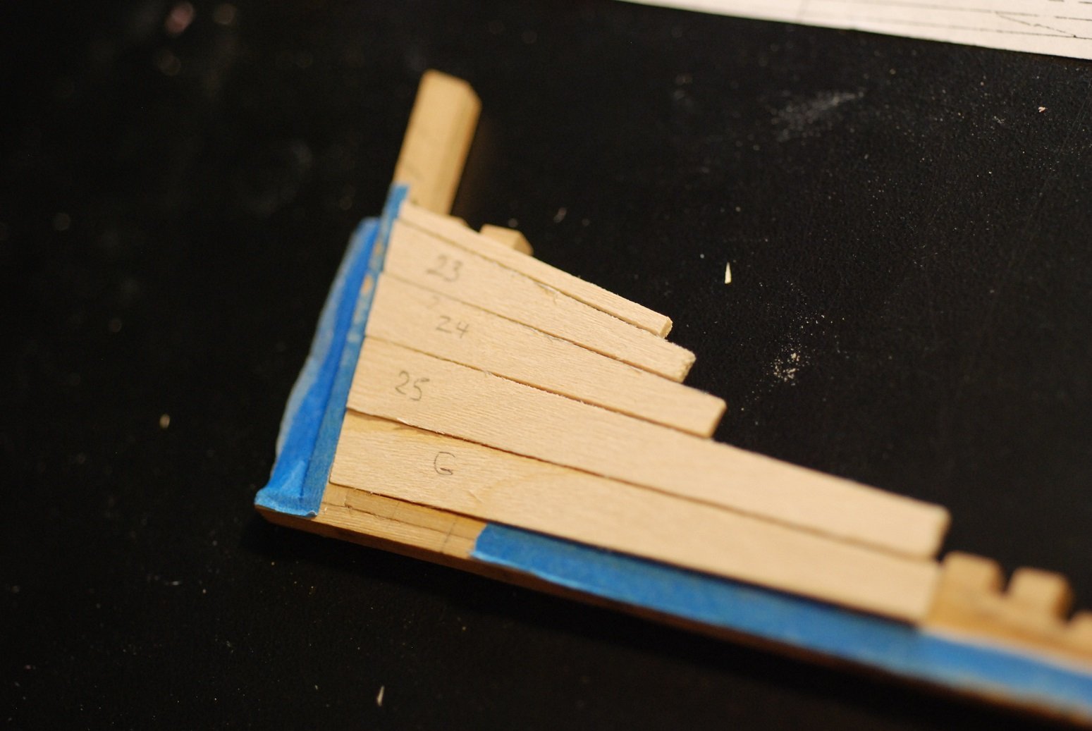
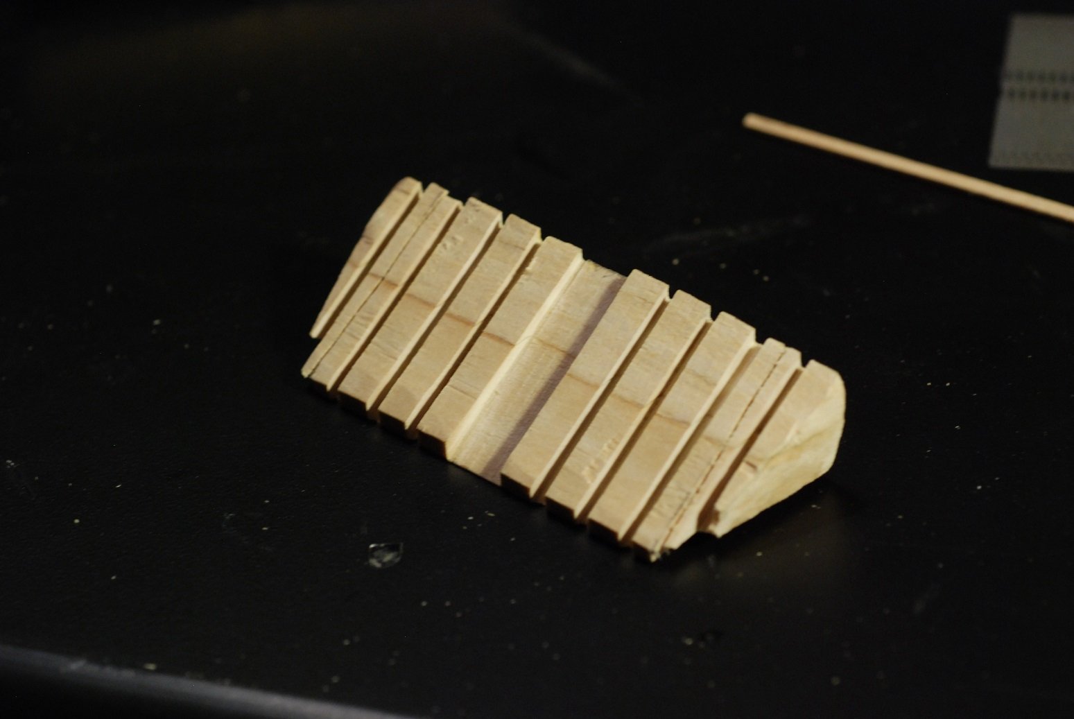
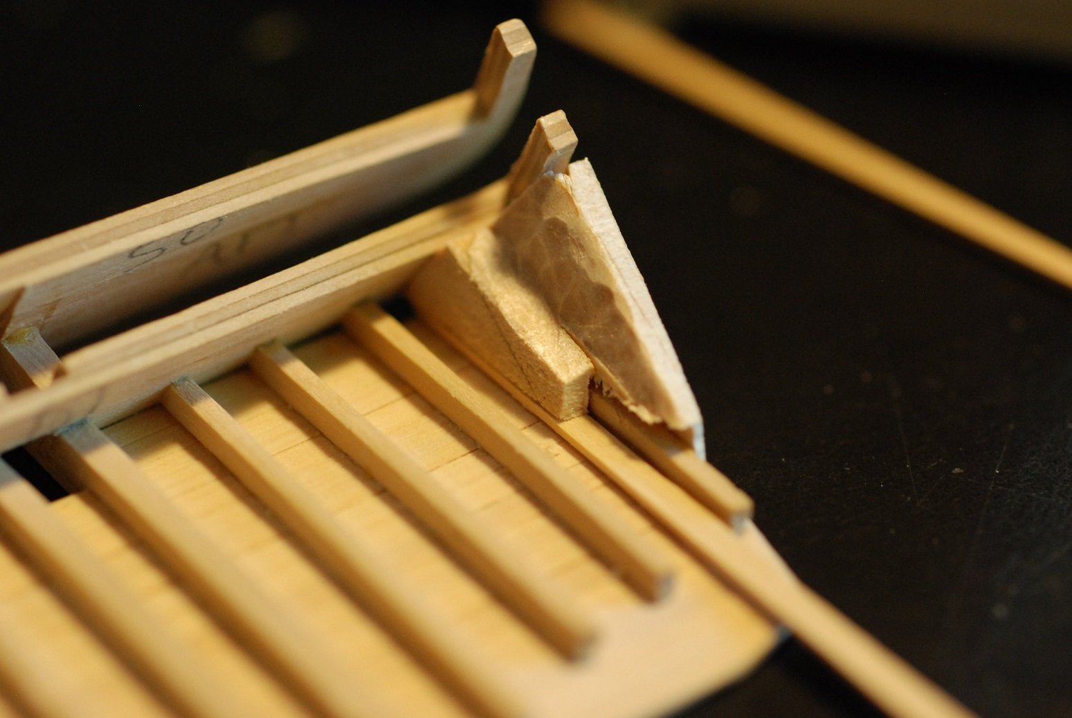
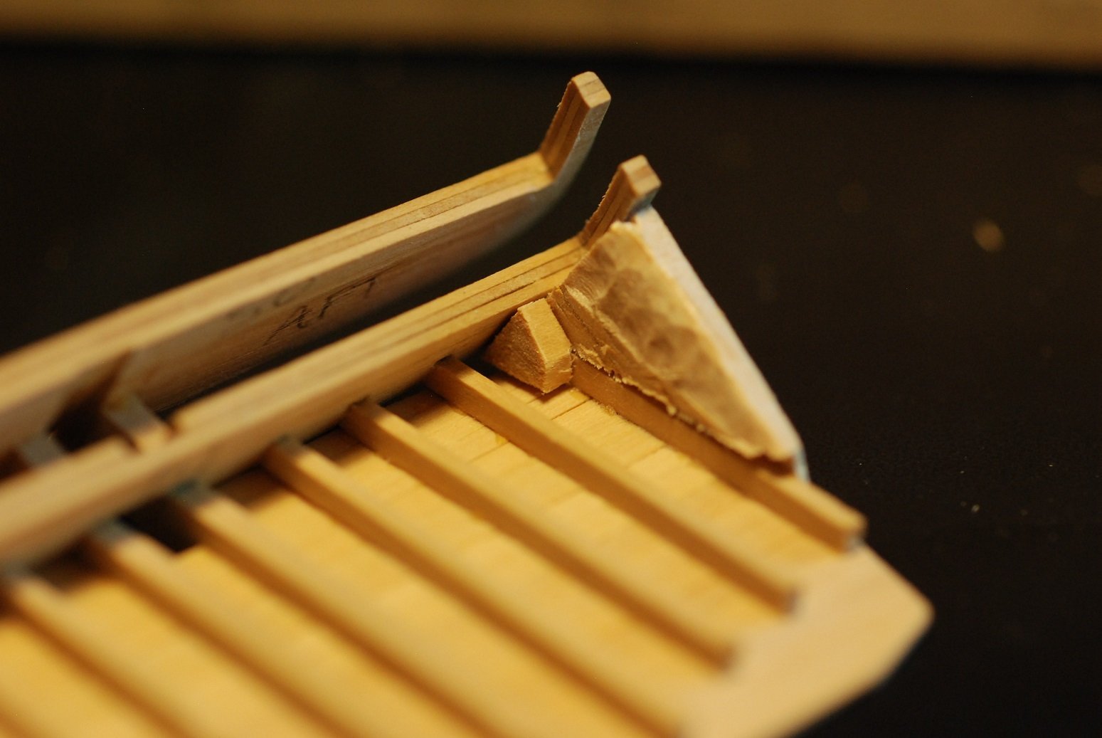
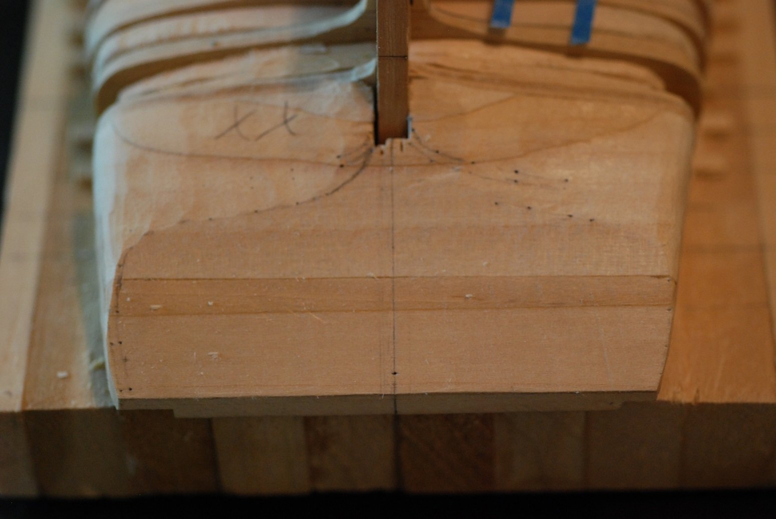
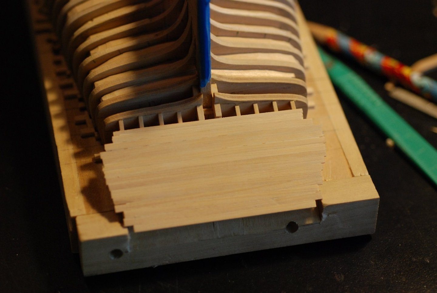
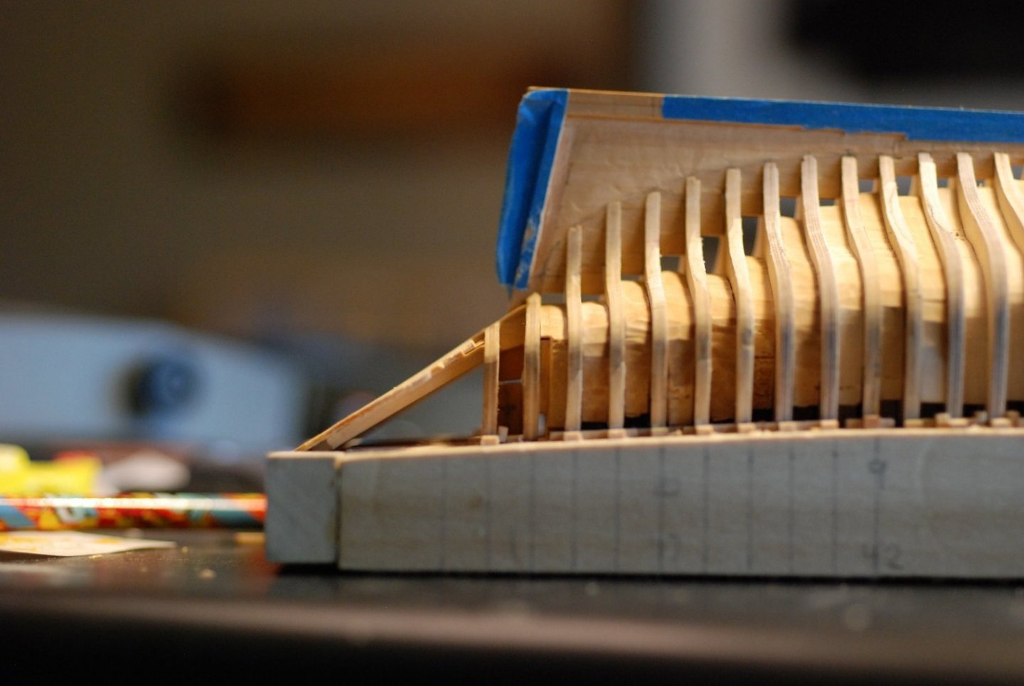
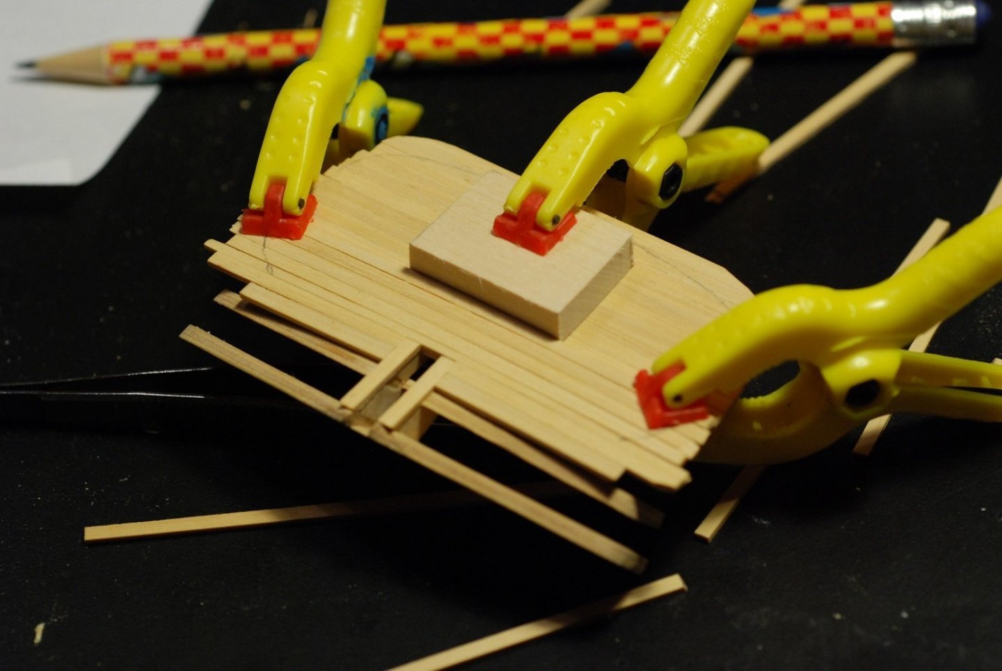
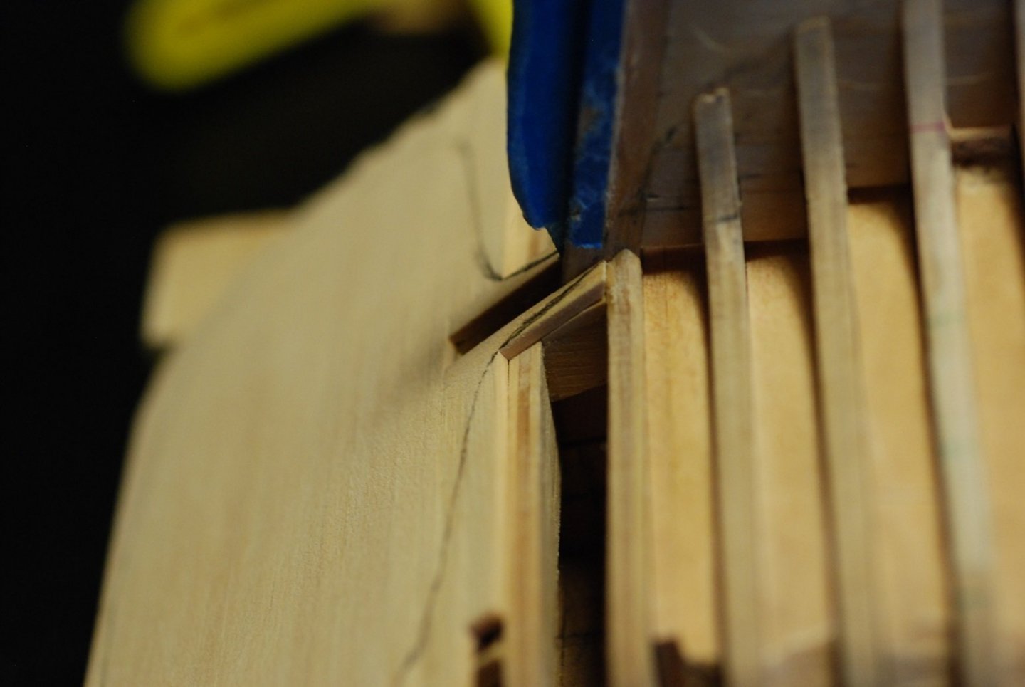
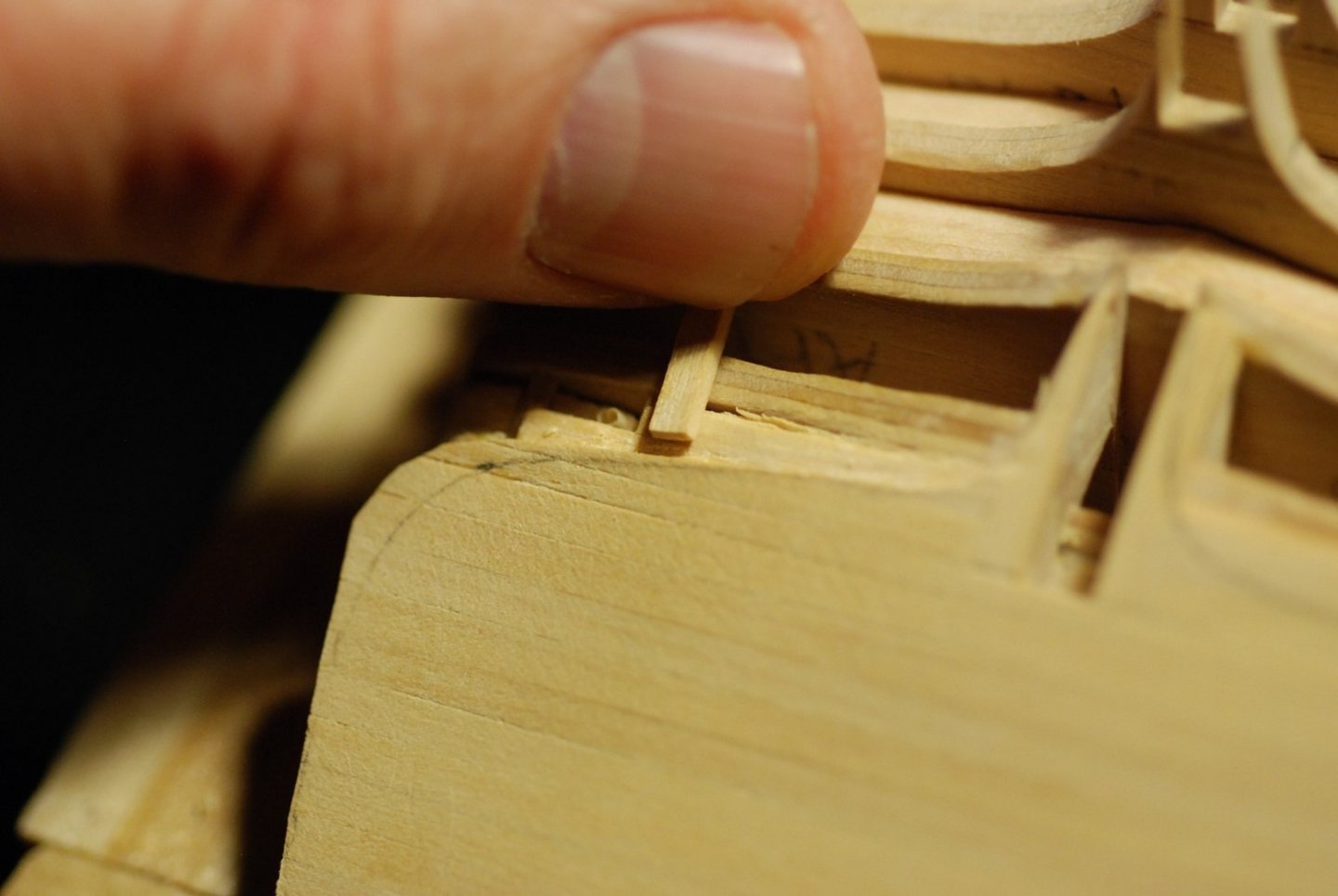
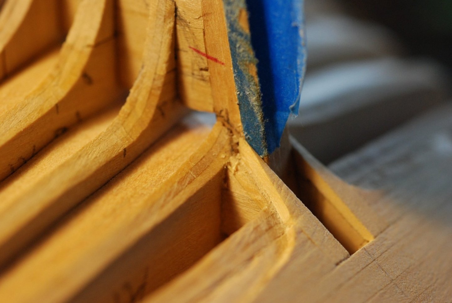
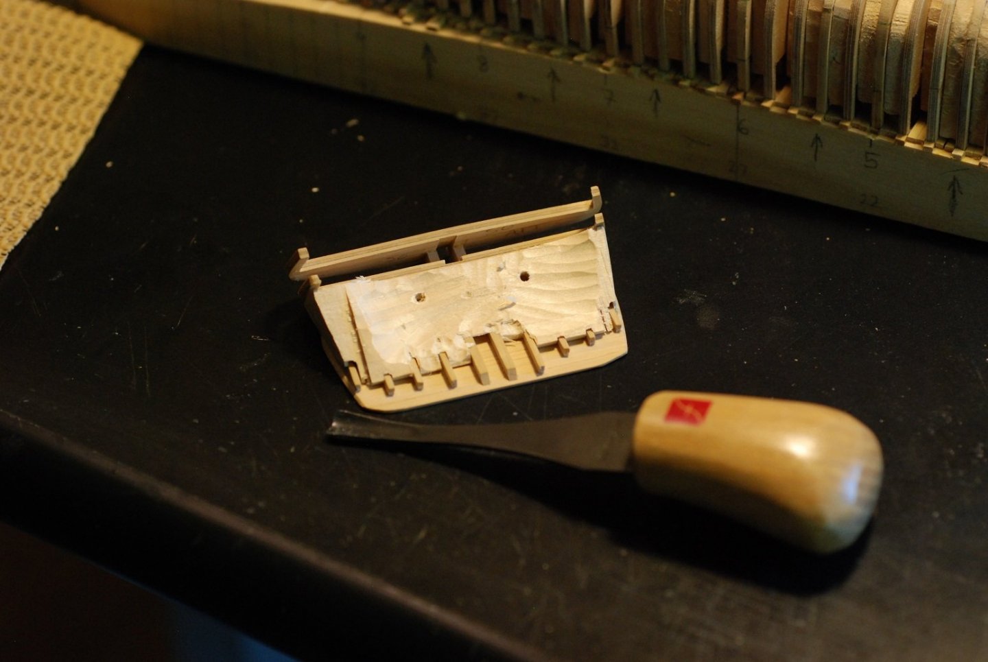
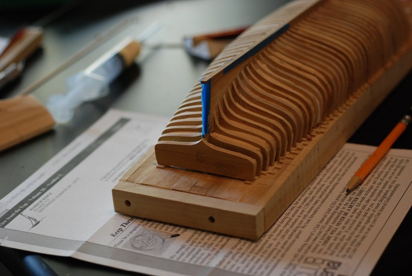
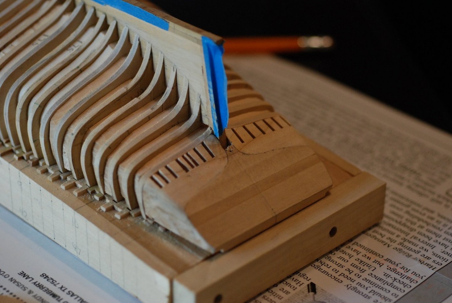
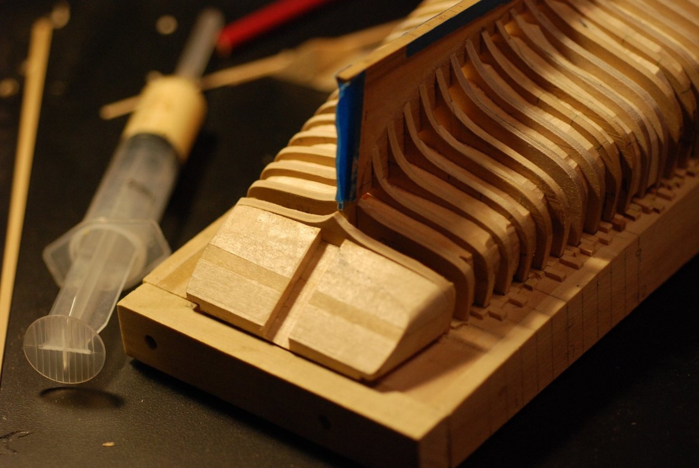
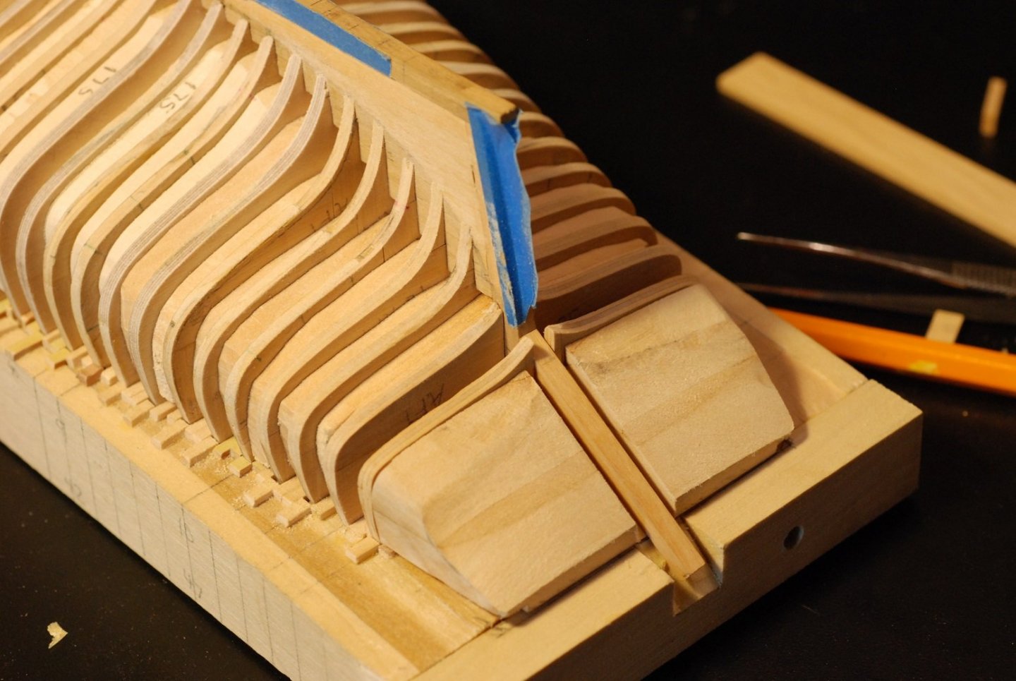
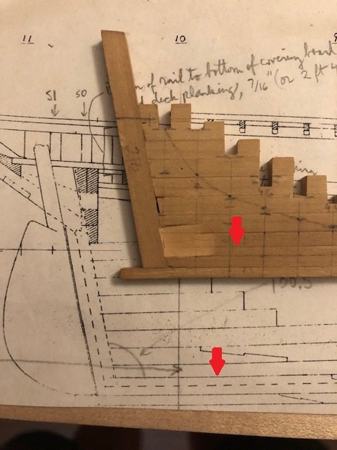
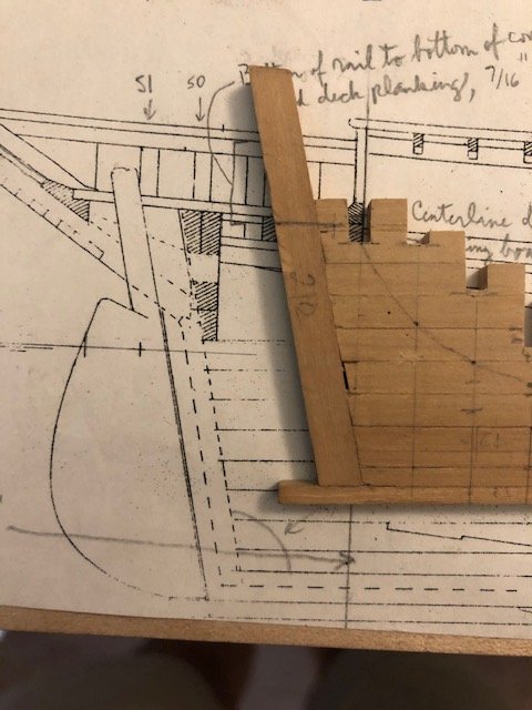
 Well, it’s been quite some time since the last post. Like last Valentine’s Day. Which in these parts was known as Snowmaggedon, when snow and ice paralyzed our metroplex but did not keep me from posting my last update. However, in the meantime, life got in the way of subsequent postings. But I did get some stuff done, as this and the next couple of posts should illustrate. I planked up the transom with Castello boxwood strips, trying to be as careful as possible to not have any seams. Planking was carried down to the point of the aperture for the rudder. I then applied a transom pattern that was developed off of the lines plan for the hull, and drew out the outline of the transom so I could get a sense of how far to trim back the edges of the transom planking. It was at this point that I began to realize that I had a problem. The current angulation of the transom has the transom planking relatively flush to the aft most frame (#51), so that hull planking would have no edge to fair into. I had neglected a certain amount of thickness of the transom planking at its bottom edge, so this area would need to be built up in order to provide enough thickness for the hull planking to meet it at the proper level. So I added two vertical strips at the margin of the aperture for the rudder, and installed another layer of planking. This layer was built up with strips of decreasing thickness as planking went upward toward the taffrail, because it appeared by my measurements that the top edge of the transom planking was ok in its position. This was again done with Castello, as I plan to plank the hull with Castello as well. Planking has been carried out to the top. The photo shows just how thin the topmost plank is, as a faint feather edge is evident between the top edge of the planking and the pencil line estimating the position of the taffrail. The vertical strips allow for defining of the edge of the transom as it approaches the rabbet on the sternpost. Now, planking has somewhere to land and to form a mitered joint with. The topmost edge of the transom planking is currently very roughly defined, and probably will remain that way until I am working on the bulwark planking. This part is tricky. Visualizing how the hull planking will make the transition from the sternpost rabbet to the edge of the transom planking is giving me headaches. I am fortunate to have a planking expansion diagram of the hull, so here I am attempting to use that in order to have a plank seam land at exactly the point where the sternpost rabbet meets the edge of the transom planking. It should be possible to make that happen when the time comes. This is how planks 23 through 25 land on the sternpost, with the garboard plank also shown. The width of these strips were determined by the planking expansion. It appears that plank 22 splits into two stealer planks near the sternpost, and it looks like it will make a good opportunity for one of them to end on the sternpost and the other to land on the start of the transom planking. We will just have to wait for now and see how that plays out. In the meantime, there will be the need for some wood to support the bulwark planking as it passes from the aft-most frame #51 to the edge of the transom. In the real ship, there is solid wood in this area beginning at the aft surface of frame 51 extending to the transom. Fortunately, the filler block I was using to support the transom framing as I built it out will probably serve pretty effectively to fill in this area. Of course, most of this piece I will not need. Only the portions at the outermost edges of the piece will be necessary. So, from the undersurface of the block, I carefully cut two narrow slits that did not go all the way through the piece. These slits are buried against the planking when the filler block is in place. I then glued the filler block carefully to the outermost stern frames along their outer surfaces, being careful to not glue any other part of the filler block to the transom framing. Here I am trying to show the relationship between the filler block, the aftmost frames, and the edge of the transom planking. I carefully cut some slits along the top surface of the filler block, and started carving out all the wood that I would not need. The buried slits I had cut earlier would be my target for carving, and once I reach them I should hopefully be able to pull out the central part of the filler block “en bloc”, as docs sometimes say. Getting closer, so I have moved to a Flex-Cut carving tool. One of the slits is coming into view, on the right side of the photo. And now I have hit the slit on the left side of the photo, but not quite on the other side. And so it worked. I was able to pull out the central part of the filler block, leaving only the edges behind. But they were somewhat precariously glued against those outermost stern frames. Further removal of excess wood required supporting some of the waste wood with a supporting strip of wood so that the whole piece would not excessively flex and break off of its stern frame. And thus I worked off excess wood. I think I will stop here, although I have made further progress. Next up will be more fairing, as well as cutting of bulwark stanchions from each frame.
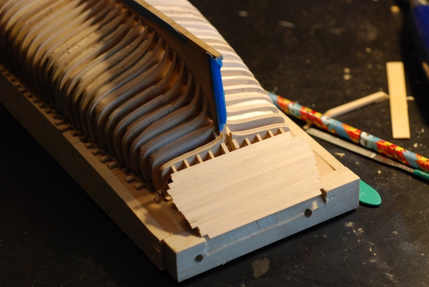


-
This probably comes too late to help you Alan, but the US Forest Service has a lab in Madison Wisconsin that will do 3 free wood sample identifications per household. This is the Center for Wood Anatomy Research. The big drawback for you is that they would ideally want a sample that is 1"x3"x6". So like half of your board. And you don't get the sample back. I will probably be sending them some wood samples so I can report back in 4 weeks how the process goes. Here is the link: https://www.fpl.fs.fed.us/research/centers/woodanatomy/wood_idfactsheet.php
-
Makes me think of the movie Terminator: Rise of the Machines!
-
Well if that's what's on the stern, that settles that!
-
I saw it in Frolich's text on ship modeling by Ancre (English translation).
-
Question for the group: I see people from Europe referring to this vessel as Le Belle Poule, not La Belle Poule. The word poule in French is in fact feminine (for chicken, or a colloquial for something that is loved), so the La would appear to be correct at first glance. But I think they may use Le because essentially we are abbreviating "Le Vaisseau Belle Poule" (the vessel named Belle Poule) to Le Belle Poule. Any insights? Anyone from overseas want to weigh in? Or perhaps this has already been discussed...
-
"Ye people, rend your hearts! Rend your hearts, and not your garments!" -from Mendelssohn's Elijah
-
Thanks Vaddoc, I am glad I bit the bullet and paid for the full version of Rhino. Huge capabilities that I have barely tapped into. I am picturing that when you describe extending the frames, you are essentially describing a Hahn-style method, with all frames upside-down on a flat surface. I would then come along later and cut the extended portions of the frames down to the level of the sheer. Is that correct? My surface is curved, following the sheer at the level where the frames and bulwark stanchions meet the undersurface of the rail. I can see how the more traditional Hahn method could lead to a more accurate leveling of the frames. Edge setting will indeed be possible, but I do plan on spiling planks. The planking will be boxwood, which will be more resistant to edge set than basswood. Also, since I plan on replicating the actual planking pattern, this leads to shorter segments of boxwood planks that would be even more resistant to edge set.
-
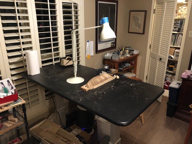
Spent today being a good boy and cleaning the workbench, putting everything away. As the captain would say, "Clear the decks for action!"
-
Thanks, Dave. Cutting the rabbet was made so much easier thanks to the microscope. Right now my challenge is finishing the shape of the transom, where the hull planks will intersect with the transom planks, as well as where the hull planks will flow into the sternpost. Fortunately I will be in Maine in March, and I will hopefully be able to look at this area directly. The challenge there is that the schooner is docked bow-to, so I would need to row around the boat to get access to the transom!
-
Good idea, Druxey. The tape didn't last very long on there anyway.
-
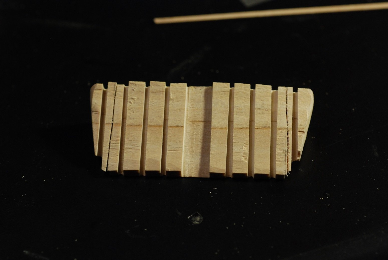
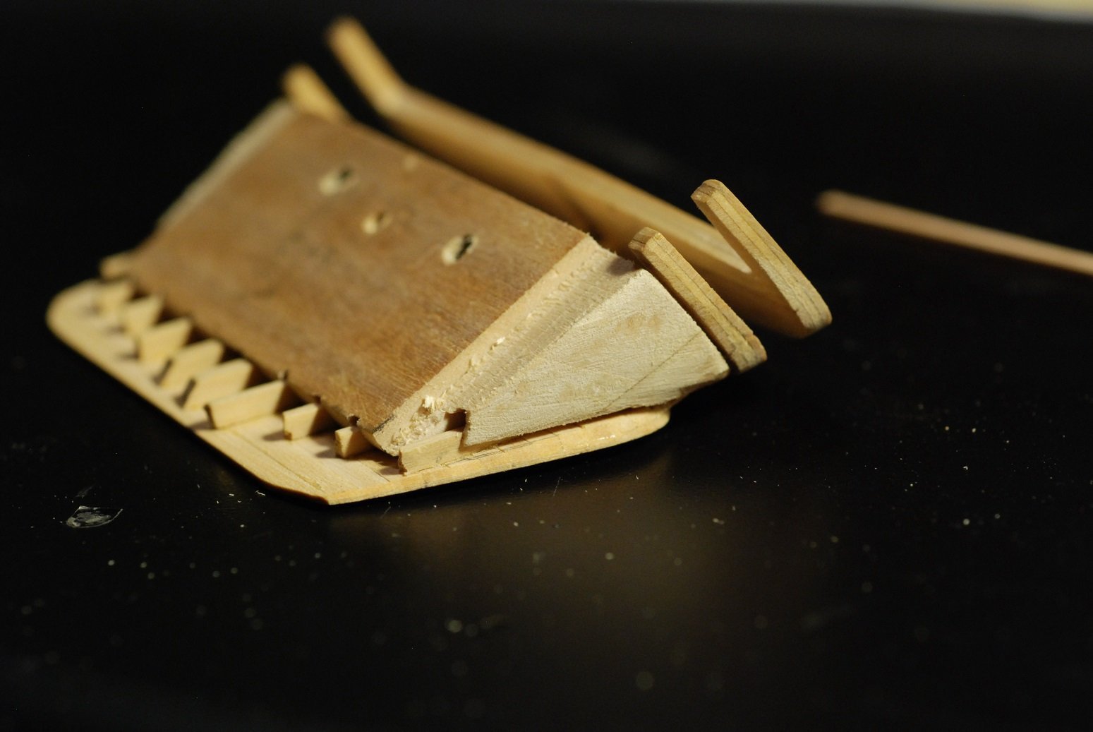
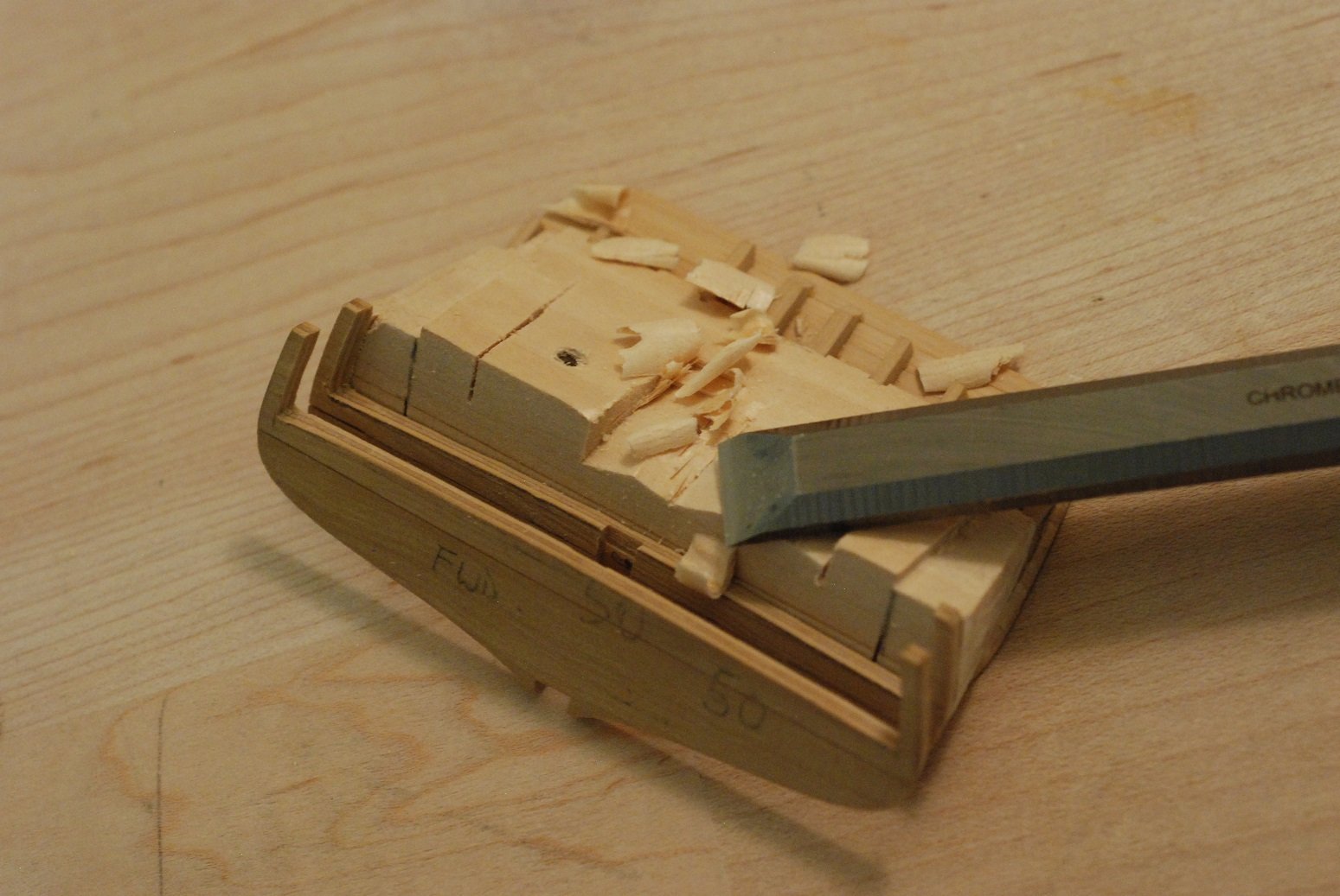
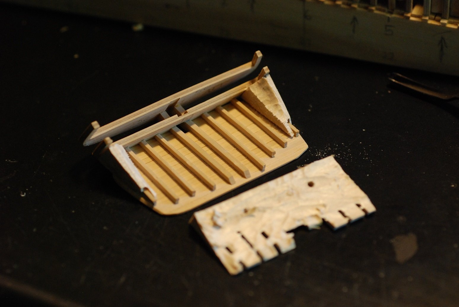
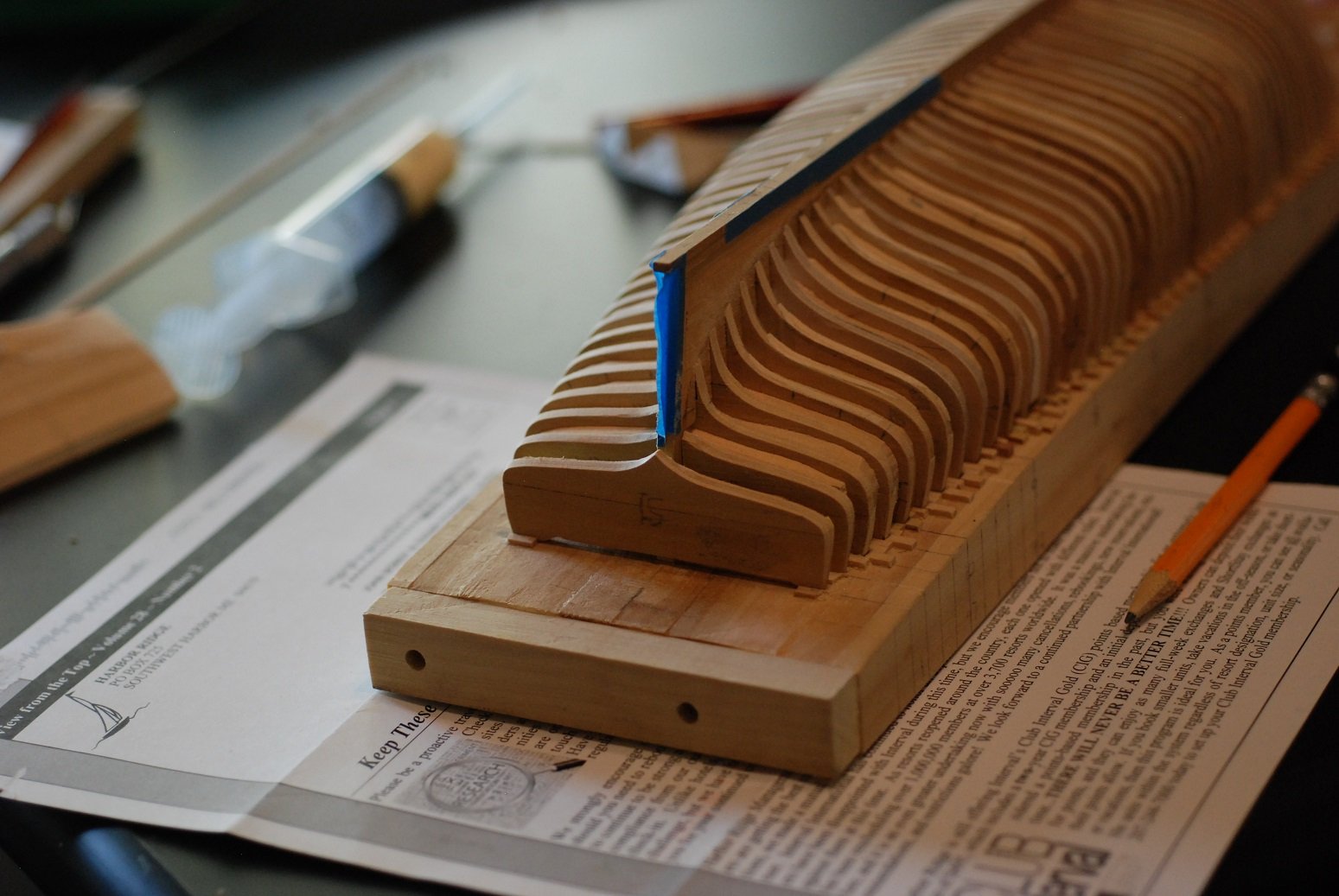
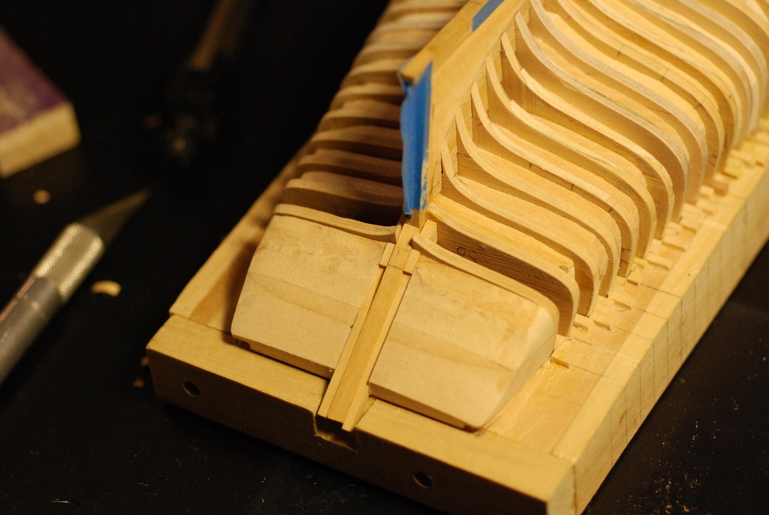
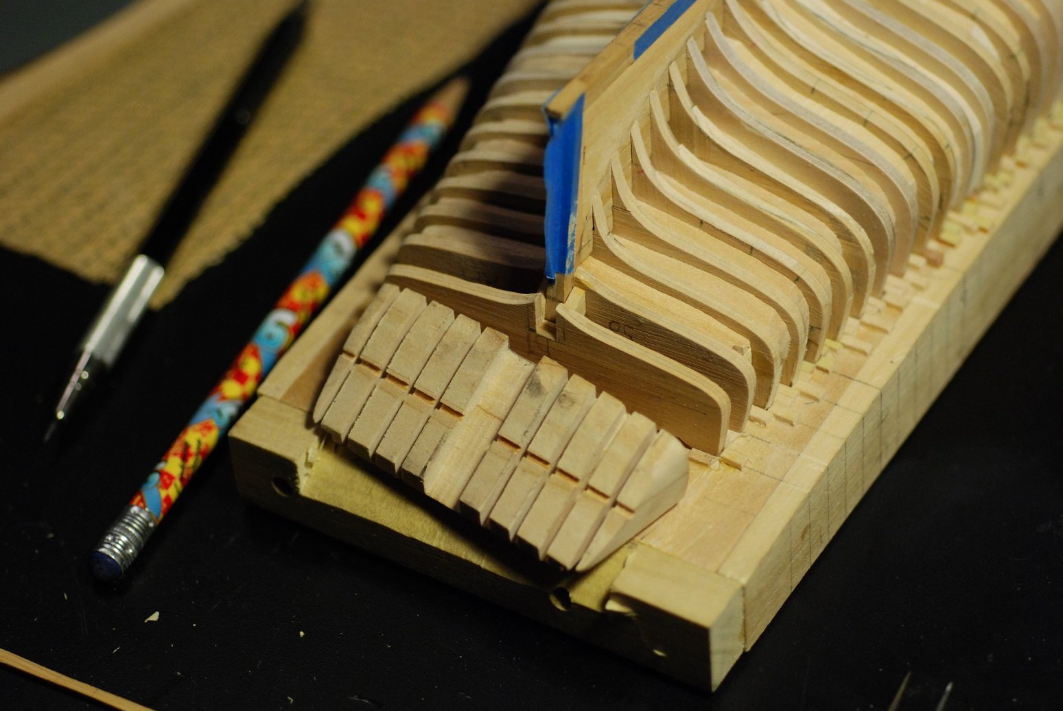
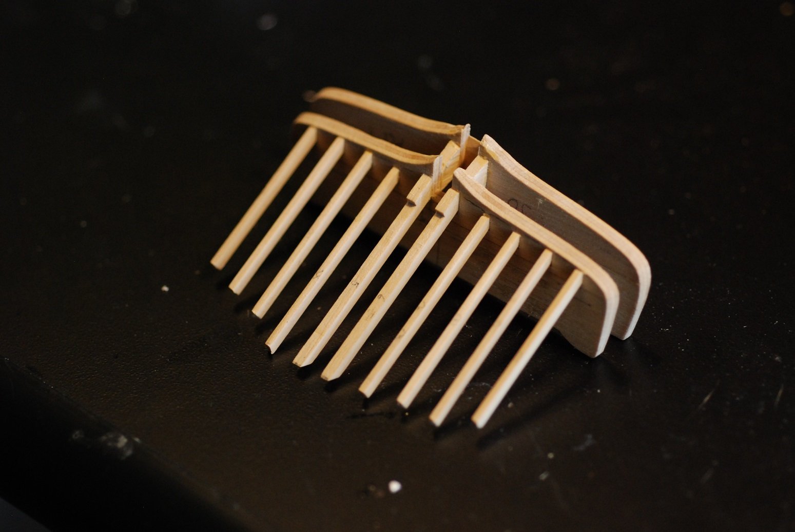
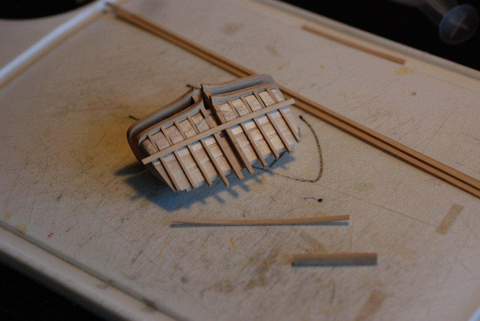
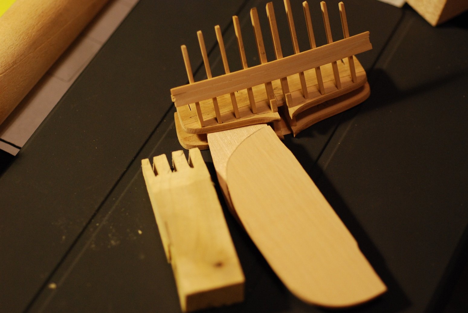
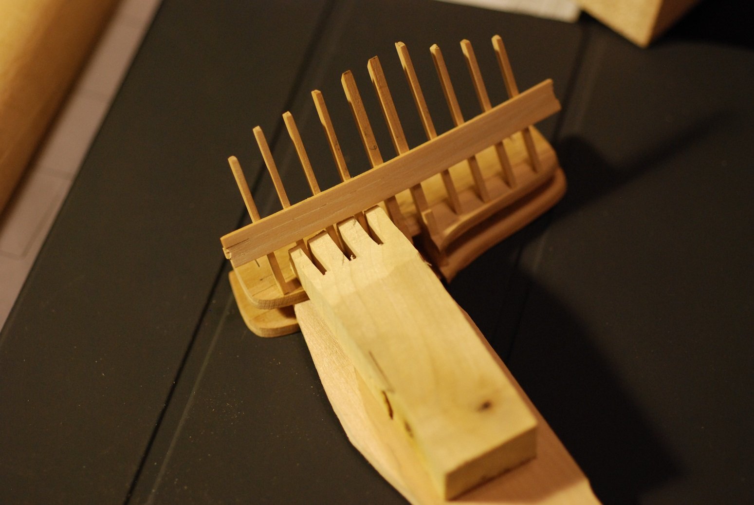
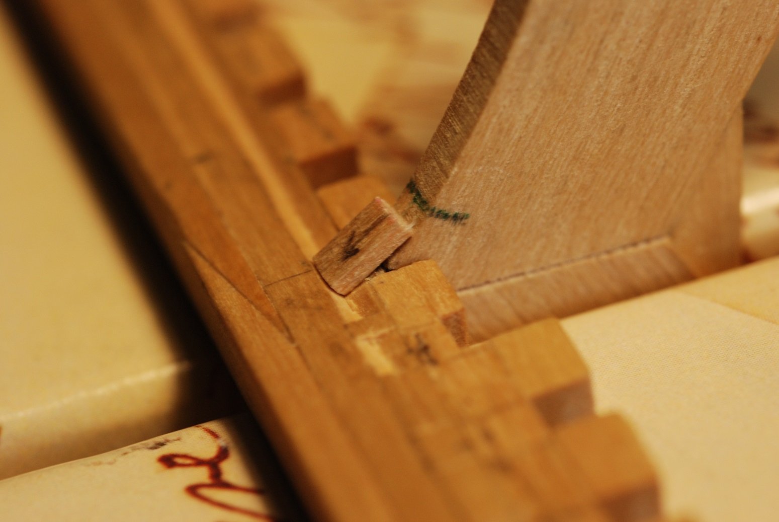
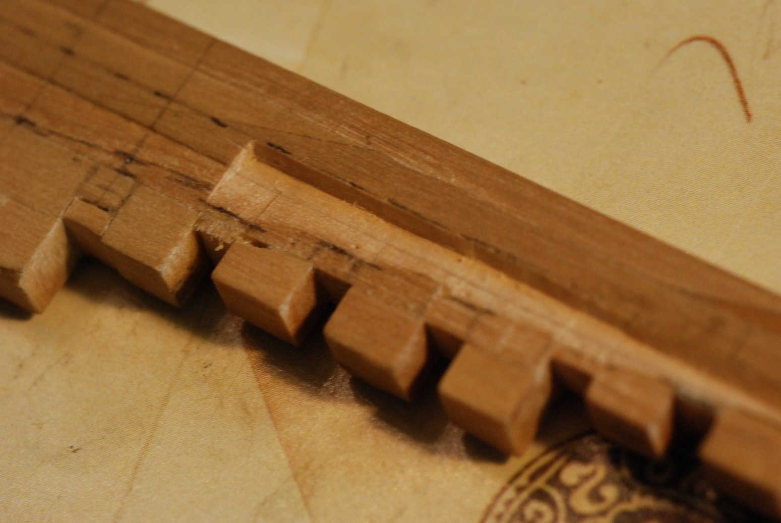
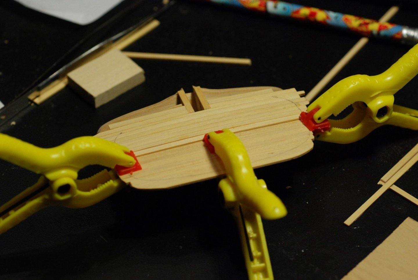
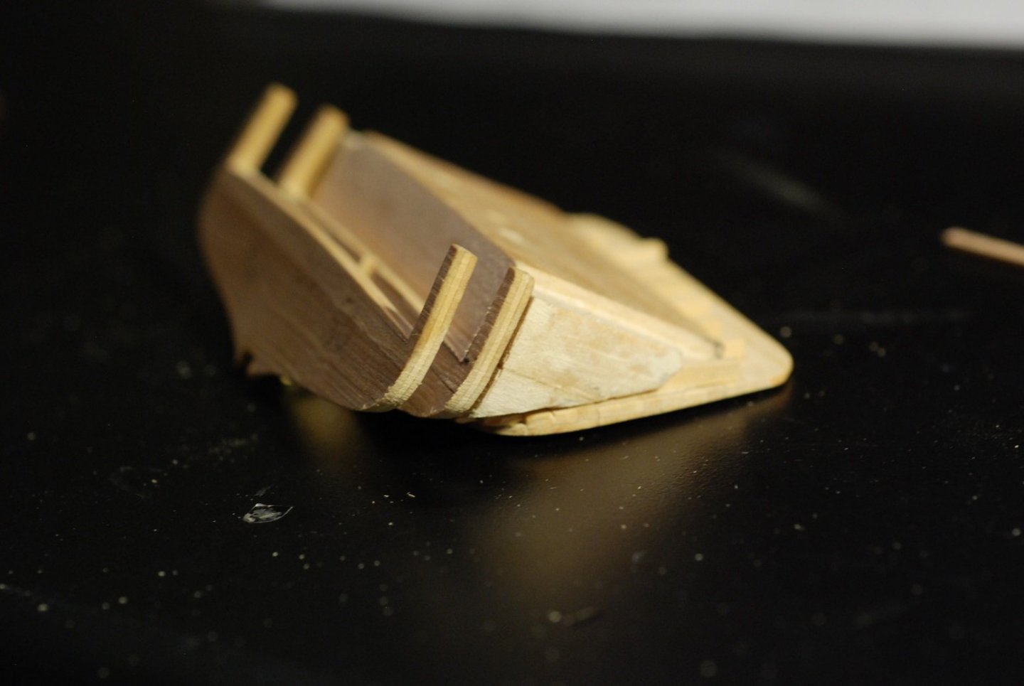
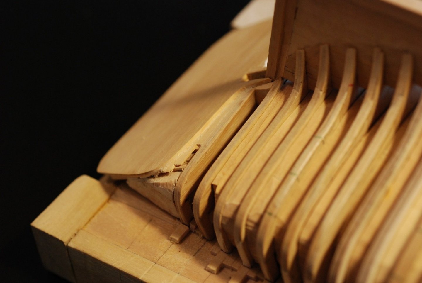
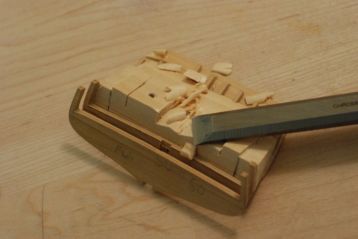
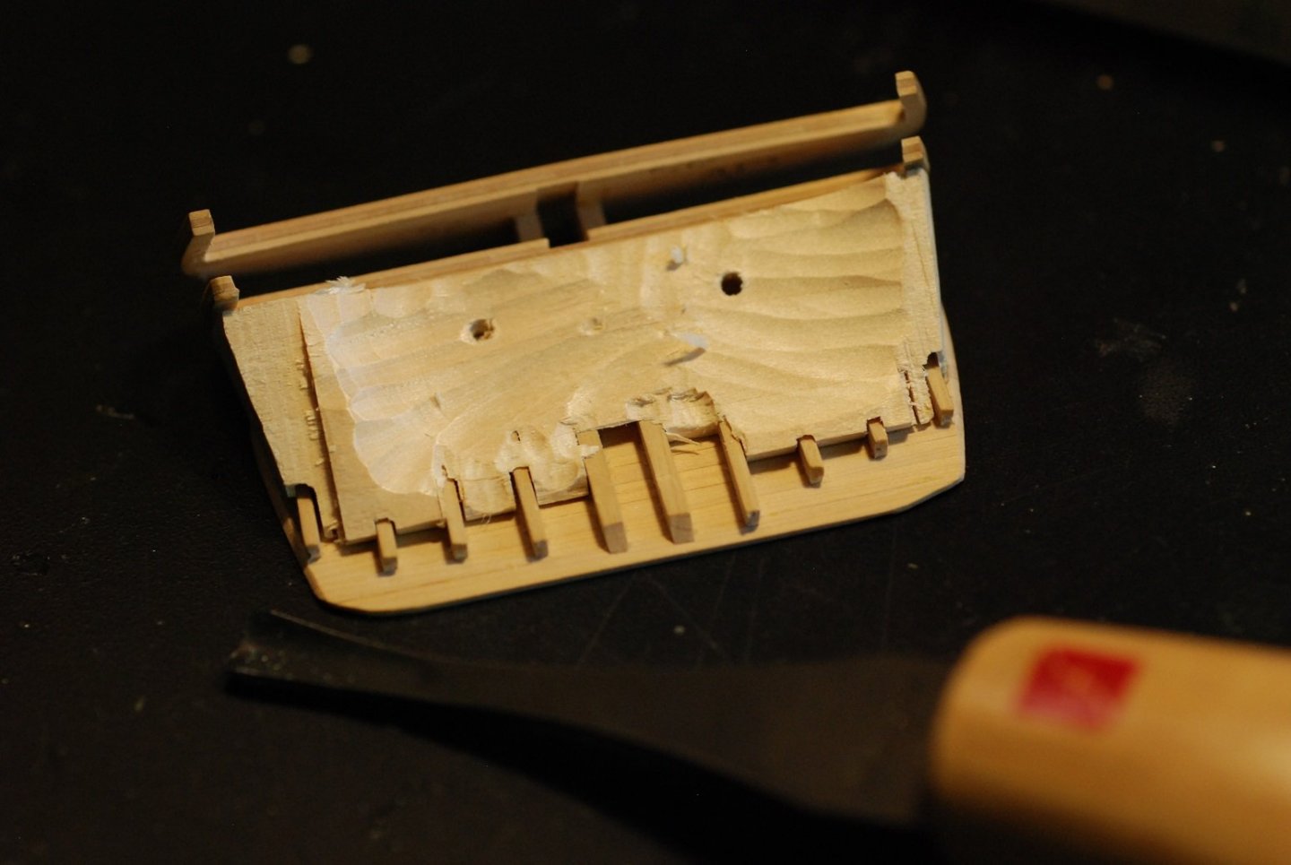
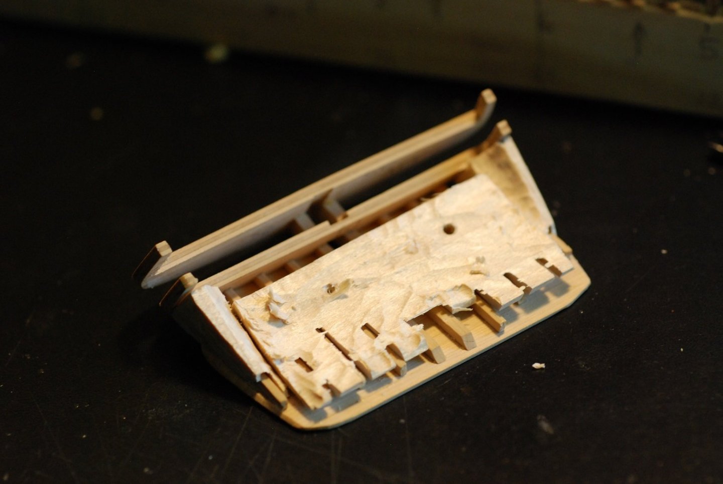
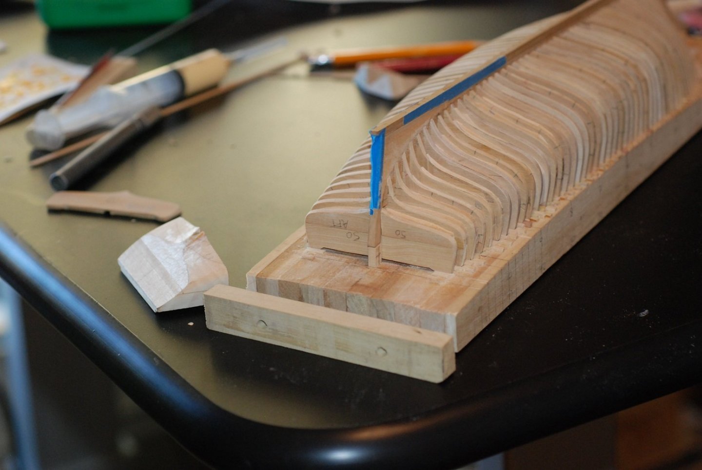
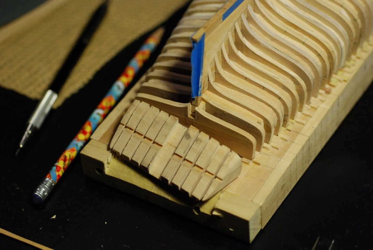
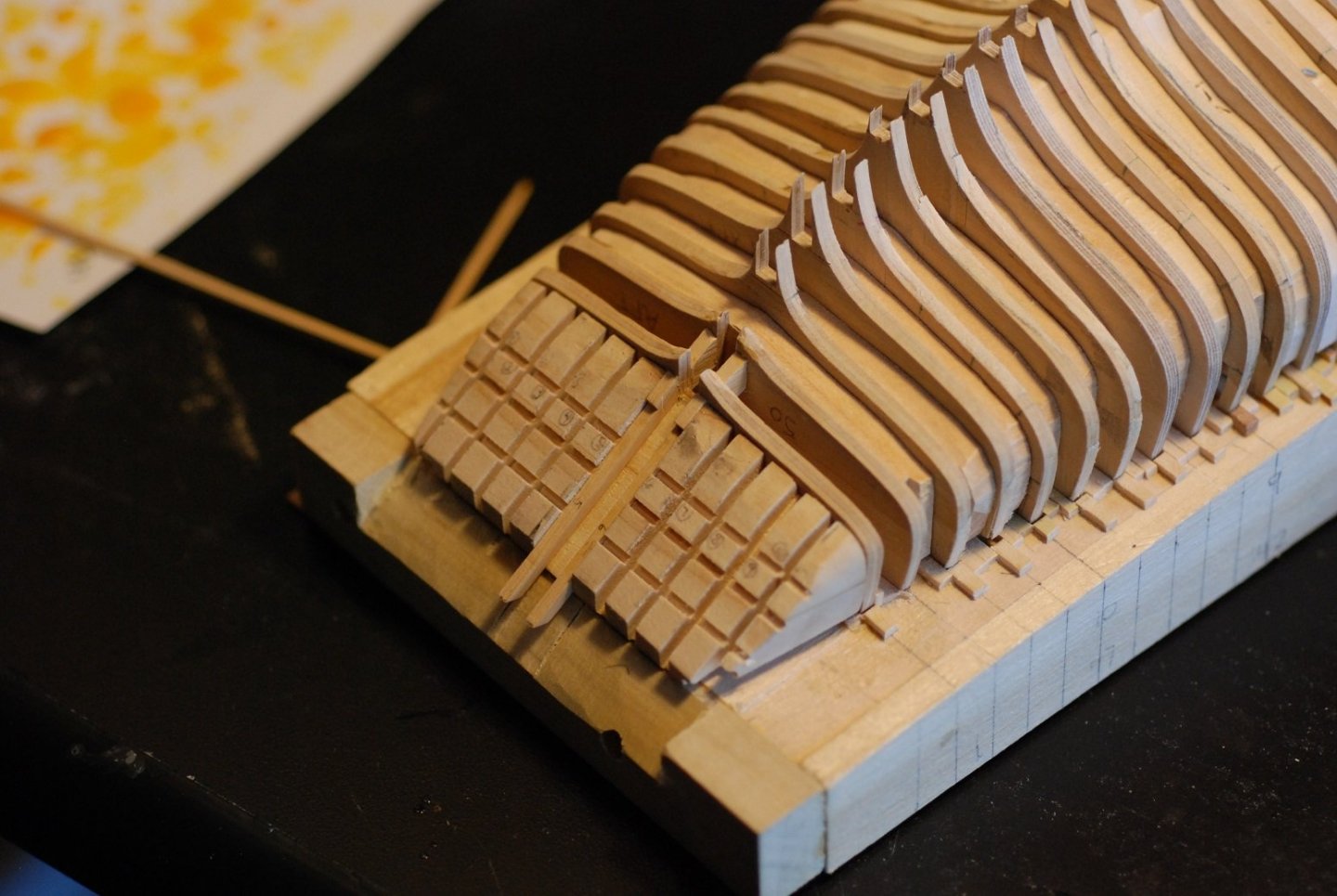
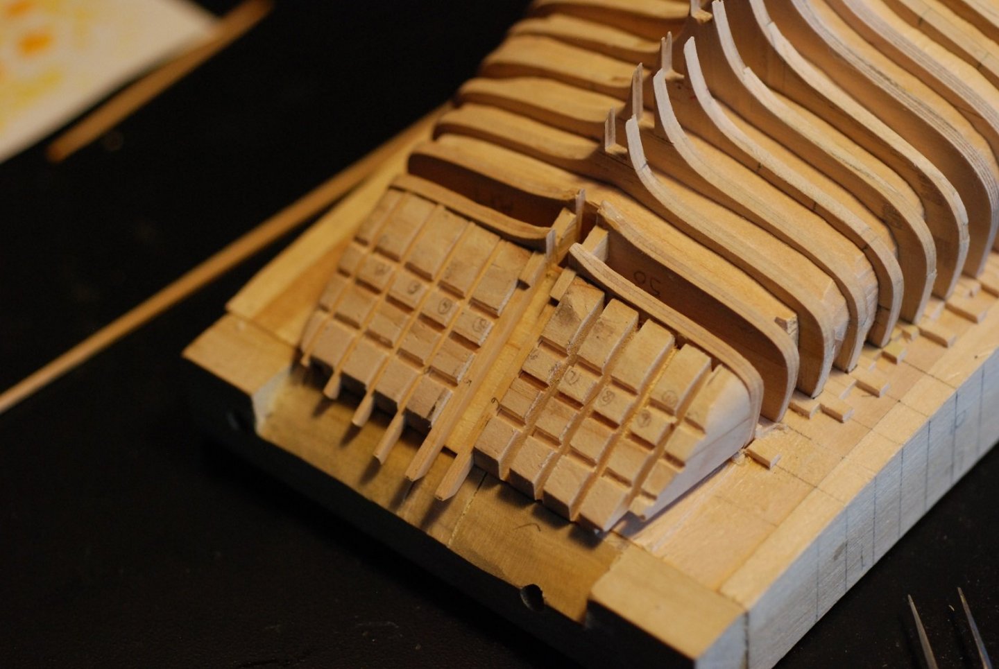
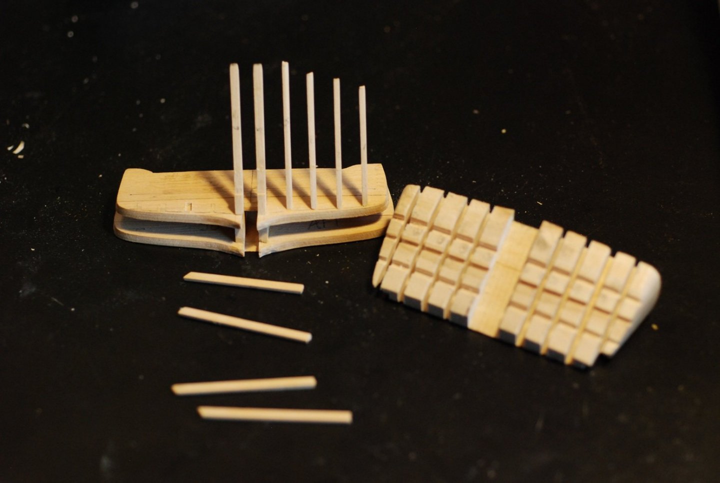
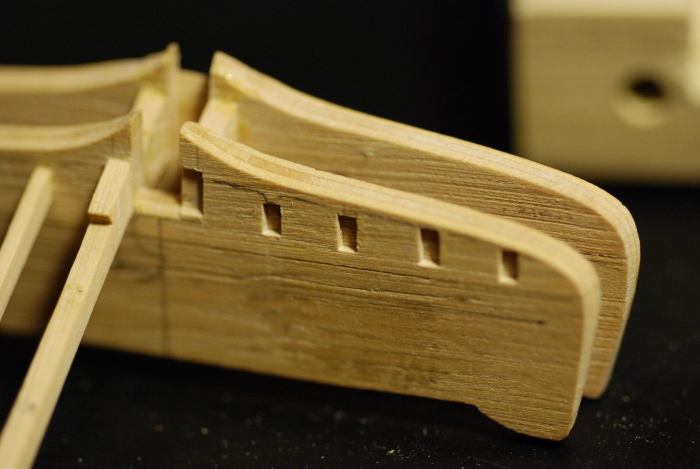
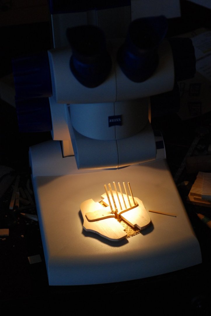
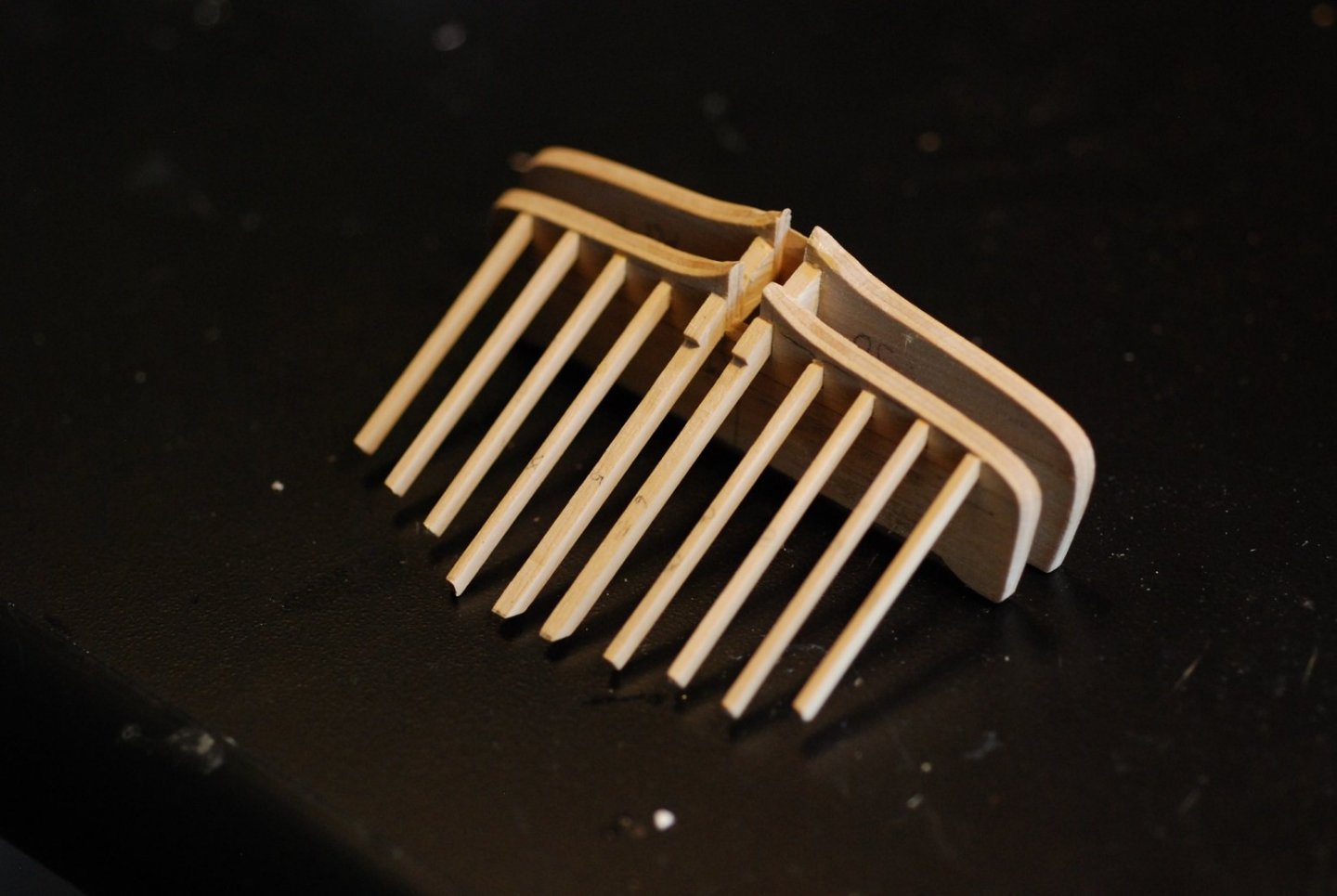
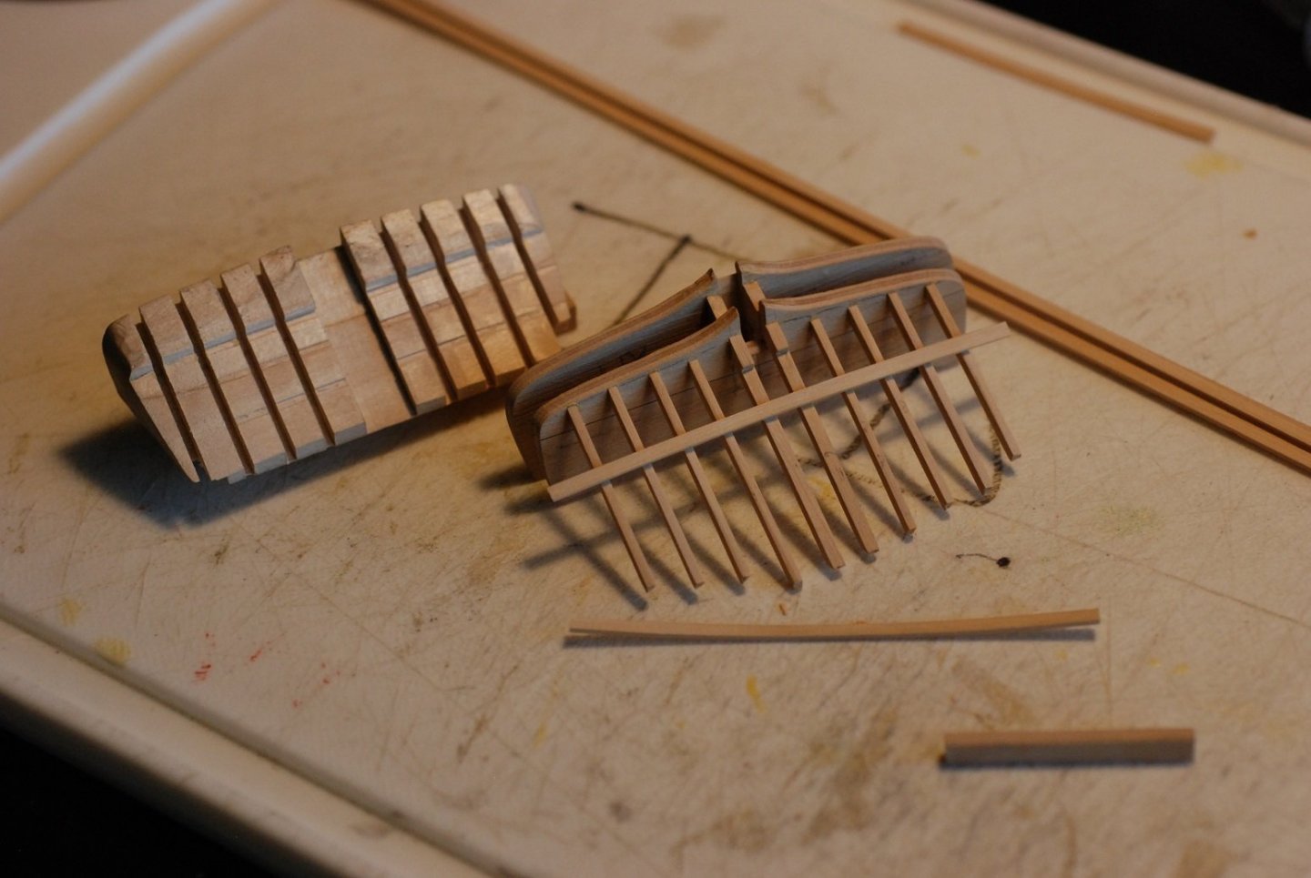
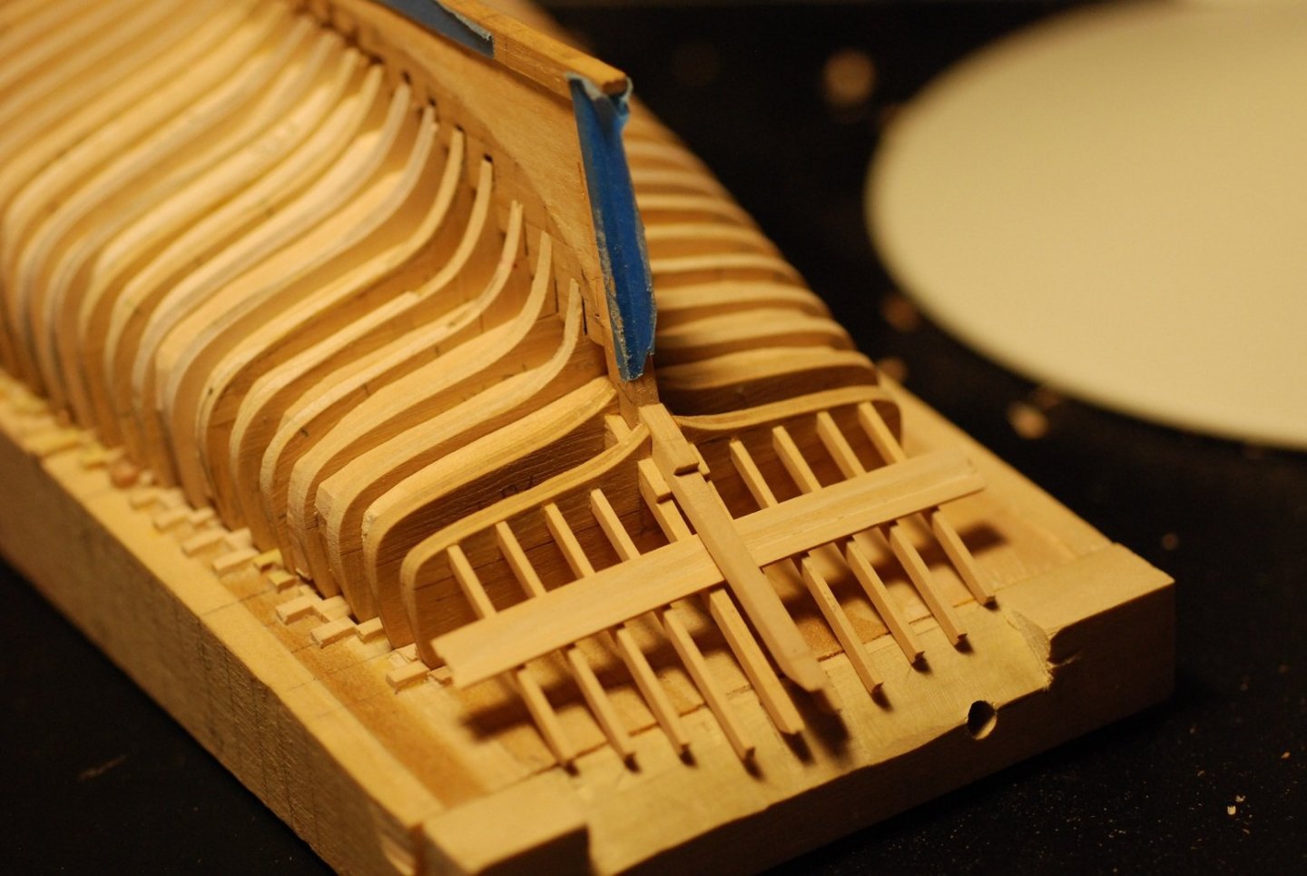
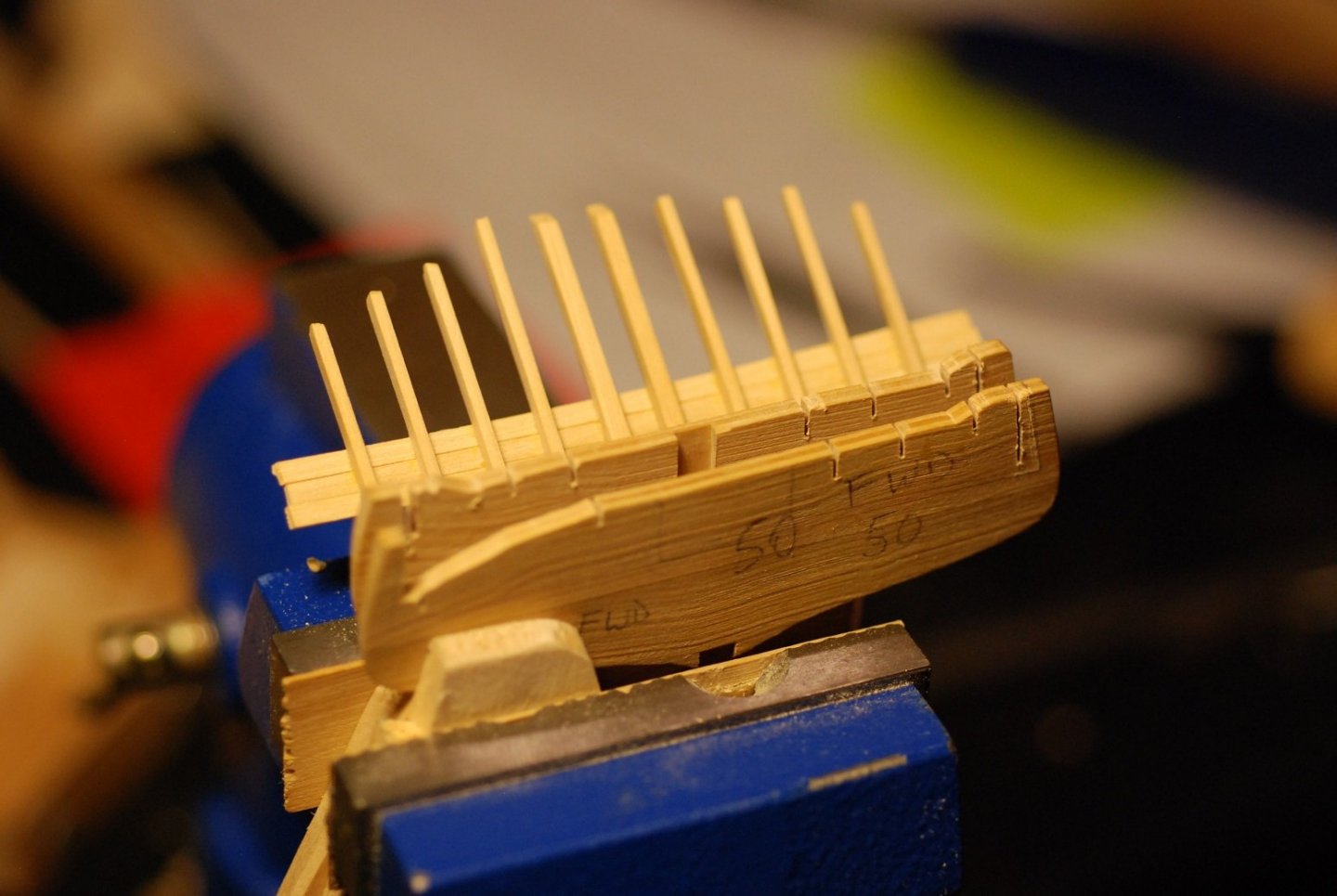
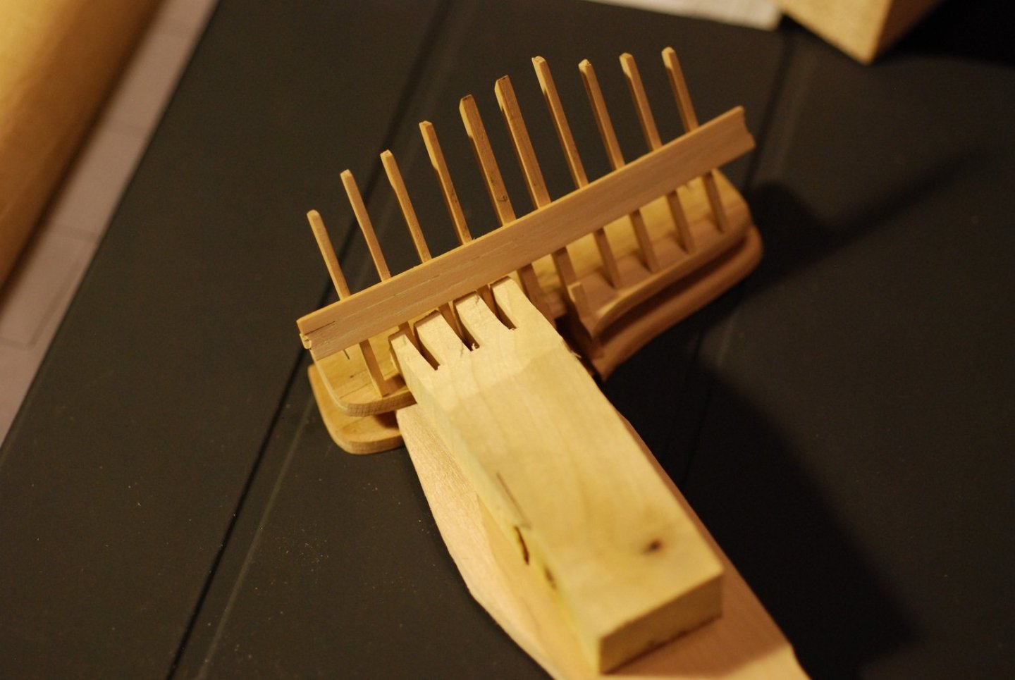
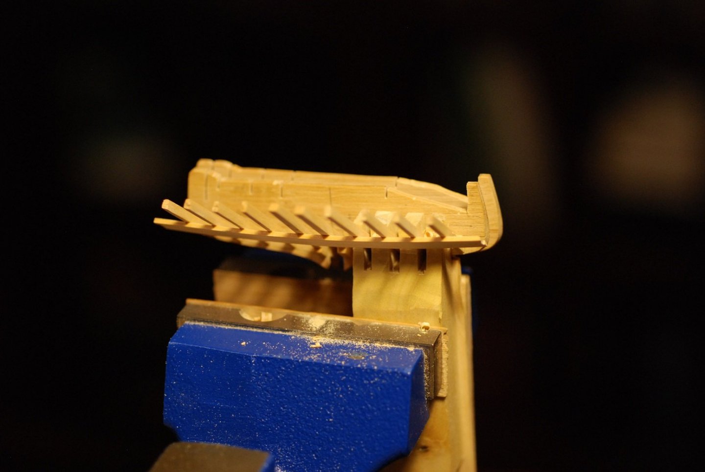
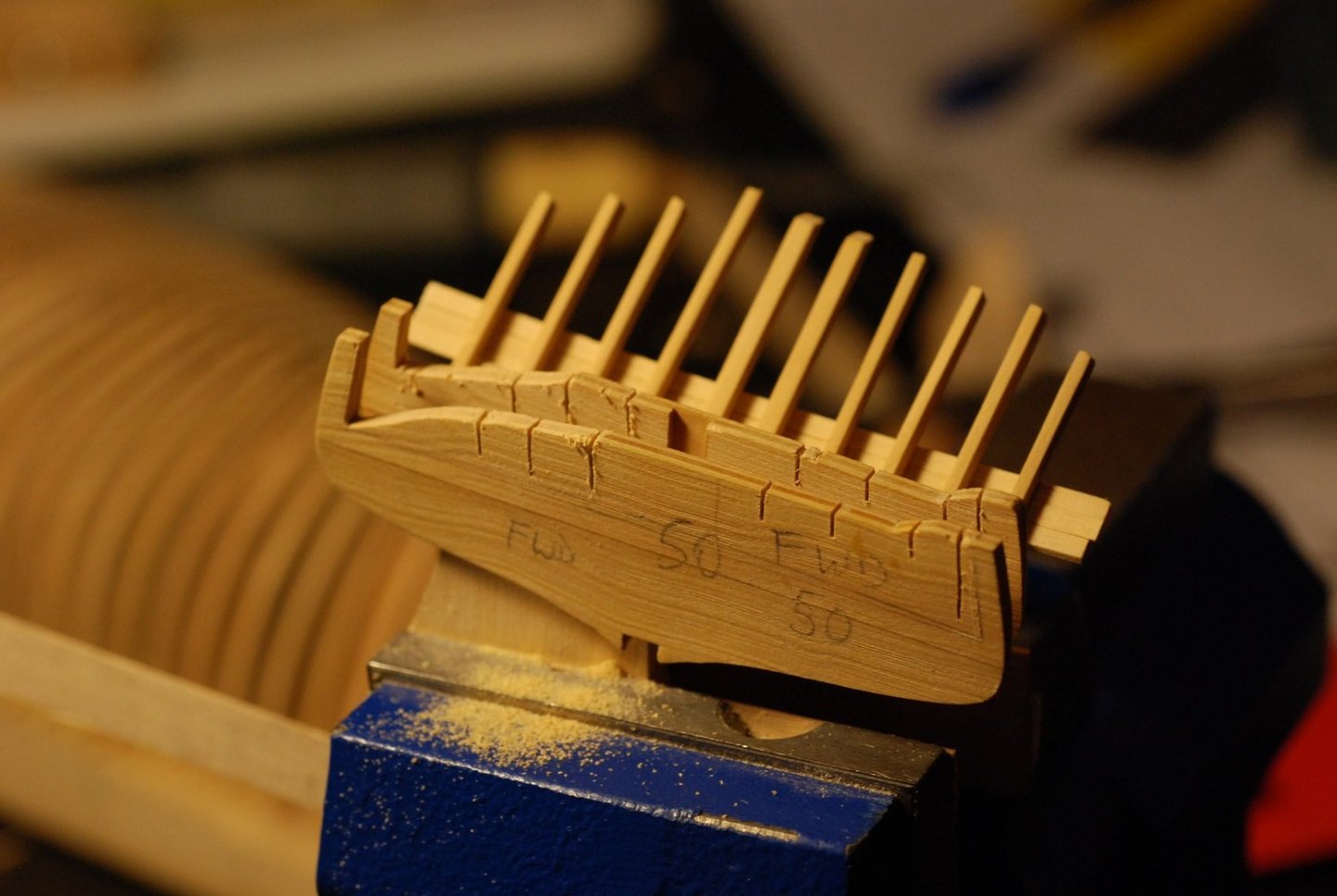
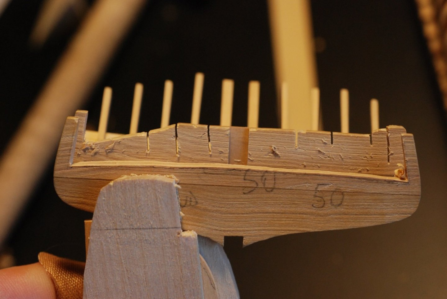
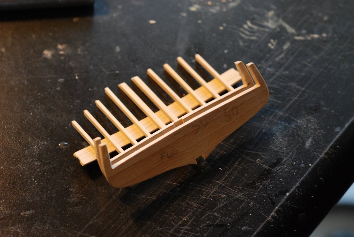
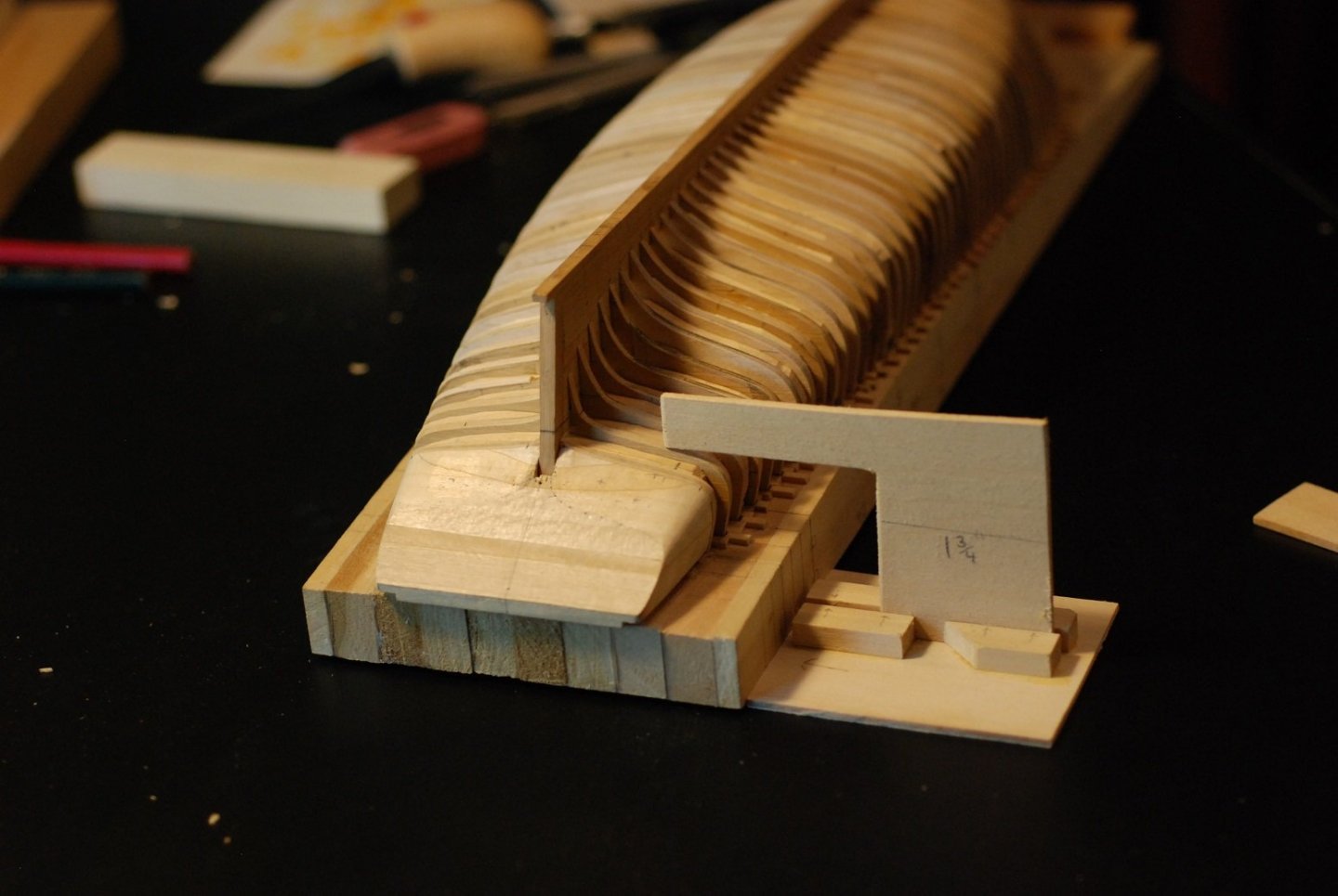
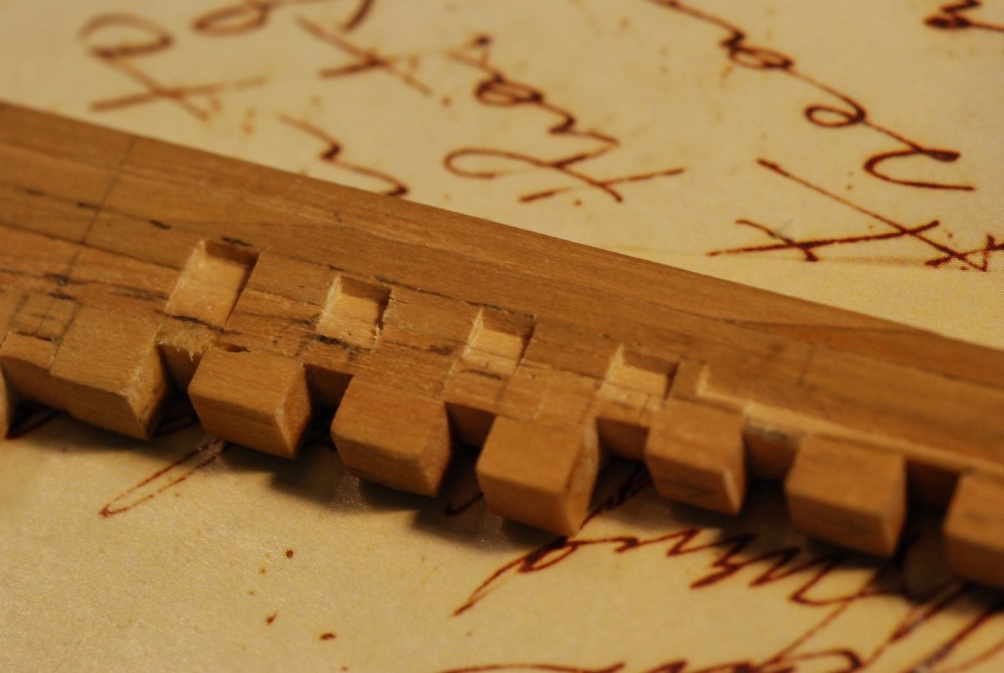
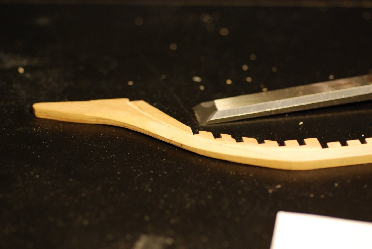
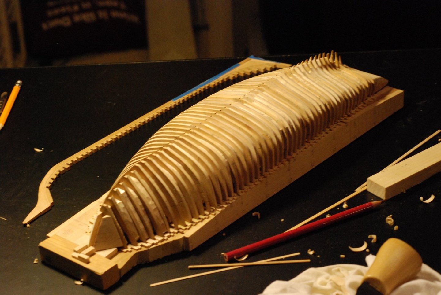
In a previous post I went over creation of a transom filler block, created by obtaining measurements off my half model of the Mary Day hanging on the wall of the shop. In order to put that filler block on the work surface, I had to extend the baseboard. In its current form, the filler block rests against the aft surface of frame #50, shown here inside of the sternpost. This wood strip was attached and the surface was planed flat with a block plane. Frame 51 is shown in place here, just aft of the stern post. Next step is to cut the transom filler block so that it can rest against frame 51. I used the table saw to cut slots of appropriate depth. These were joined to form a flat surface that would rest against frame 51. In the centerline, a large timber extends aft from the sternpost and supports the transom planking in the centerline. To accommodate that timber (I will call it a horn timber, which would be correct in other designs but I’m not sure if it’s the correct term for a schooner such as this), a slot had to be created in the centerline of the transom filler block. Plus the plans show additional smaller timbers on each side of the horn timber, so the slot was made wide enough to accommodate all 3. A slot also had to be created in frame 51 to accommodate the horn timber. Transom framing has been added on each side of the horn timber, which enabled me to go ahead and attach that horn timber to the sternpost. The plans indicate that transom planking only begins a certain level above the sternpost, so these smaller transom frames are notched at that point where the transom planking begins. Next I carefully marked on the filler block the location of the other transom frames, and used the table saw to cut slots in the filler block to accommodate those frames. There are a total of 5 frames on each side of the horn timber. At a certain point, I remembered that the transom is not flat across its face, but it has a certain degree of camber. The builder’s plan and line drawing were able to give me a sense of the degree of curvature, and at this point the filler block was sanded to a curved surface on each side. So each of the most peripheral slots had to be deepened to make sure that once they were glued in place, they would form a curved surface for the planking. I only remembered to mention this as I was putting this build log post together! The filler block in place with the most central transom frames and no keel/horn timber assembly. The starboard side transom frames have been glued using straight butt joints against the aft surface of the last frame. All the transom frames were glued up, but I came to realize very quickly that the butt joints were not stable enough for practical use. So I pulled them off… …and went to the microscope to carve out mortises that would receive each transom frame. Since the assembly consists of frames 50 and 51 joined by some blocks adjacent to the centerline, the outside edges of 50 and 51 are unstable. I stabilized them with the pieces of wood shown above, slotted in between the two frames. Transom frames are being glued in place again, and glue squeeze-out was carefully removed using the microscope. That results in an assembly that looks like this. The frames are still solid sheets of wood at this point. To carve all the wood out from inside the frames would leave a very unstable and fragile structure. So the plan is to carve out the wood to the level of the deck beams, leaving the bulwark stanchions in place. To further stabilize this modular transom assembly, I decided to go ahead and apply some transom planking. The first plank is in place…see if you can figure out the problem I just created. The horizontally oriented slots in the filler block helped to make sure the plank was perpendicular to the transom frames. It is pretty cool to separate this modular structure from the transom filler block and find yourself with a stable assembly. I started with a solid block of wood, and through process of wood elimination I will hopefully end up with a respectable transom assembly that actually resembles the real hull framing structure. Two more transom planks have been added before I figured out the problem I had created. I think I was out of the room when I thought…wait a minute, I can no longer put the keel/horn timber assembly into the transom framework! I walked back in, and sure enough, when I tried putting the keel back in place, I ended up with this. The solution was to separate the horn timber from the sternpost, with the plan to make it part of the transom assembly. Now to eliminate more wood. I had to figure out how to carefully carve out wood I didn’t want from frames 50 and 51. But to carve carefully, I would have to figure out how to hold this complex structure steady. So in the above picture, frame 50 is clamped between two thicknesses of wood that are separated by a sheet of wood that is the same thickness as the frame it is holding. Plus I have some grippy rubber material in there too. Holding frame 51 still is more complicated, due to the transom frames. So I slotted out some wood from a block that would fit between the frame and the planking that had been applied. Looks something like this. This is positioned high in the clamp for the sake of the picture. In order to actually do any carving, though, the clamped frame would have to be low in the clamp to minimize movement. A Japanese crosscut saw was used to slowly and carefully create the slots in each frame. They could only go to a certain depth before they would be in danger of cutting the transom planking. Then I used a ½” chisel under careful control to slowly cut away material from the frame while leaving stanchions behind. Despite all that care and control, you can see how the chisel would still hit frame 51 and leave behind lots of little cuts. Fortunately the affected wood of frame 51 will be removed later on. Finished removing wood from frames 50 and 51, for now. The deck camber was marked by using patterns for deck beams I had created earlier. Wood was removed up to those pencil marks, but not beyond. I figure there will need to be deck fairing later on. This has been fun creating this modular transom structure! I plan to harvest the outboard edges of the filler block and install them to the transom assembly in order to define the outer surface of the transom and to give the bulwark planking something to key into. Big decisions lie ahead when it comes to hull planking. I honestly don’t know what I am going to do after planking the transom and trimming its edges to accommodate the hull planking. But things just seem to be making themselves apparent to me as the work progresses, which is really cool.


-
Fortunately for us, the COVID infection itself was relatively mild! But an especially scary prospect given that every day I look at chest X-rays of people whose lungs are filled with infiltrates from COVID pneumonia.
-
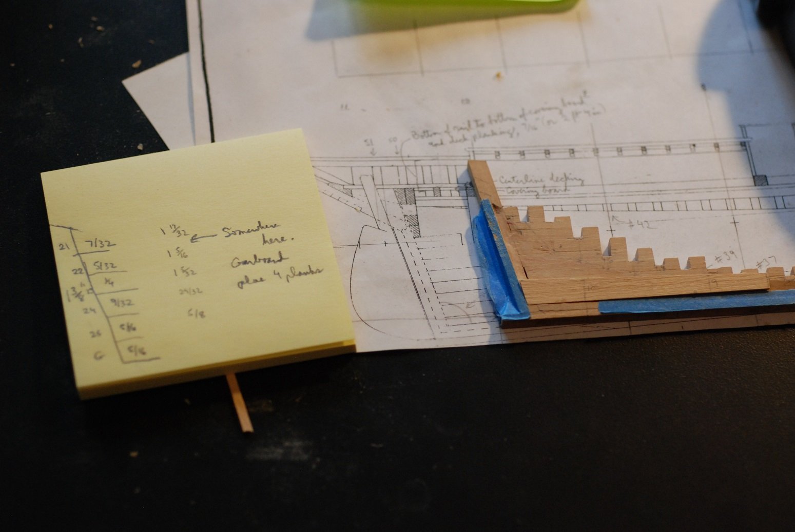
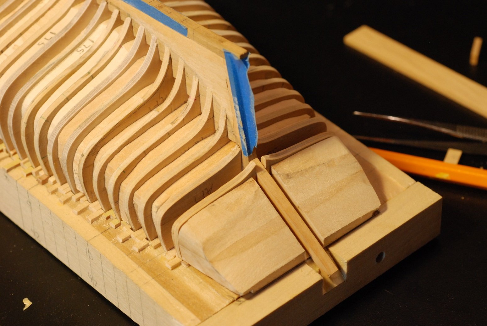
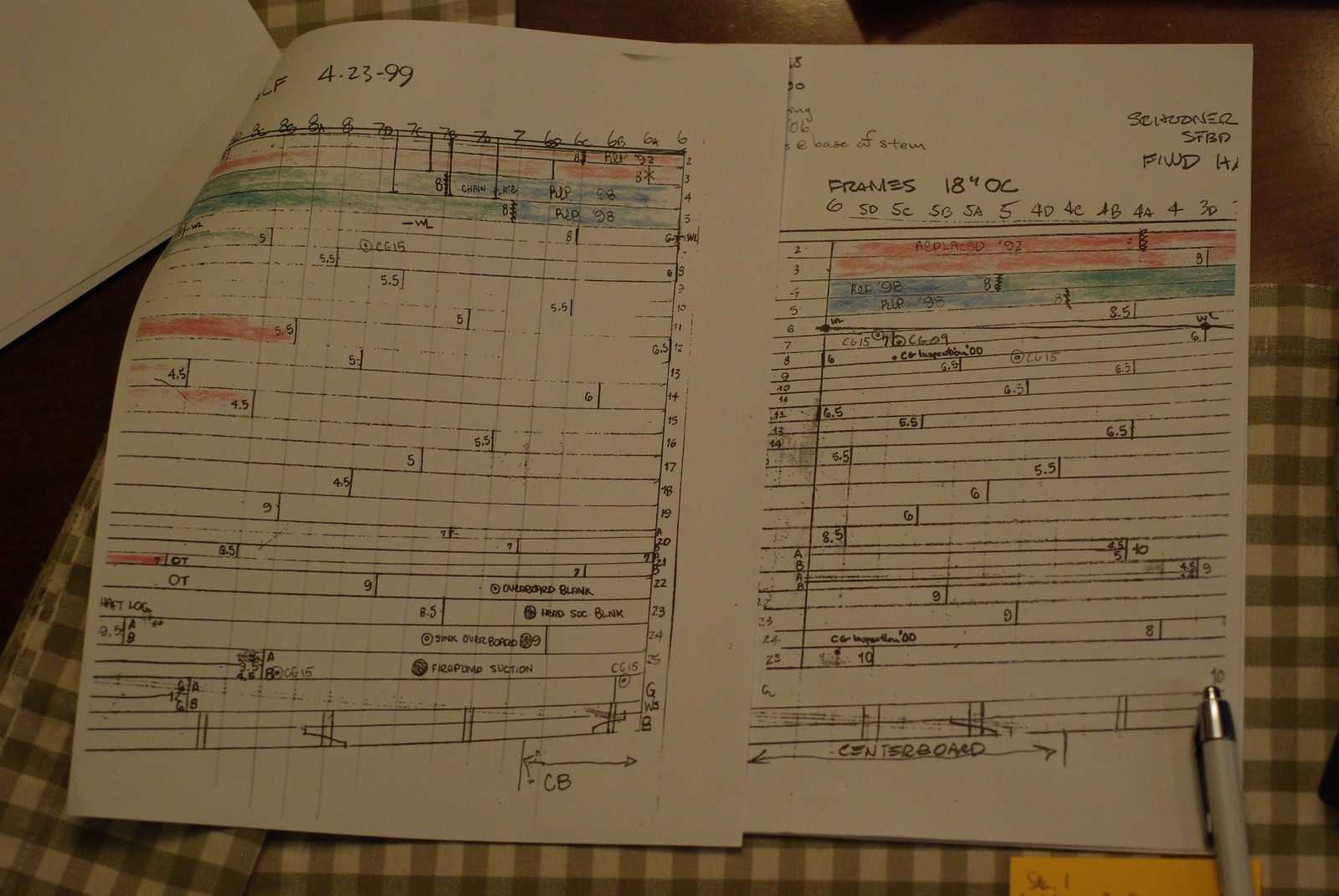
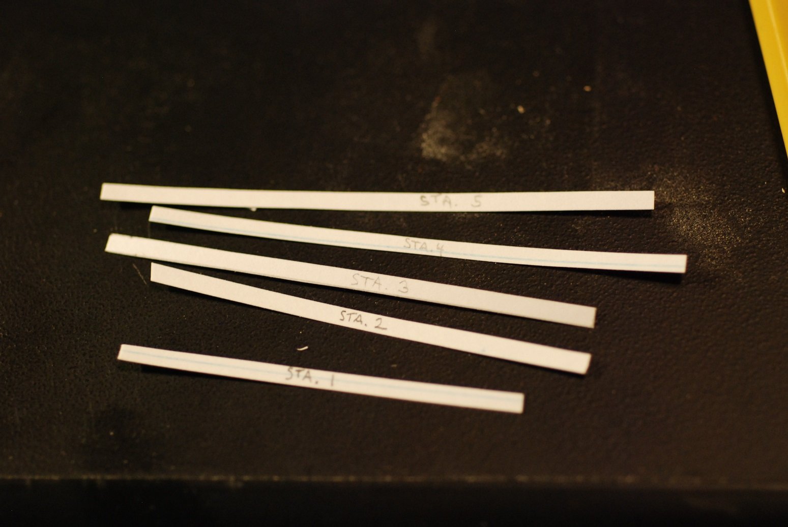
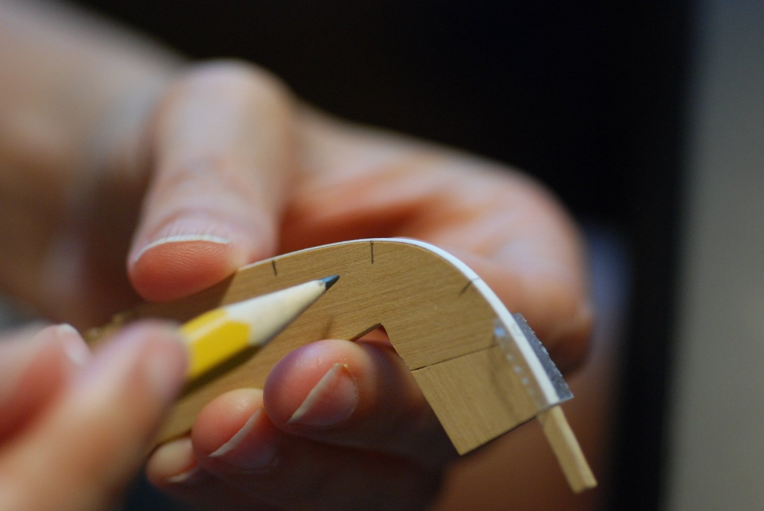
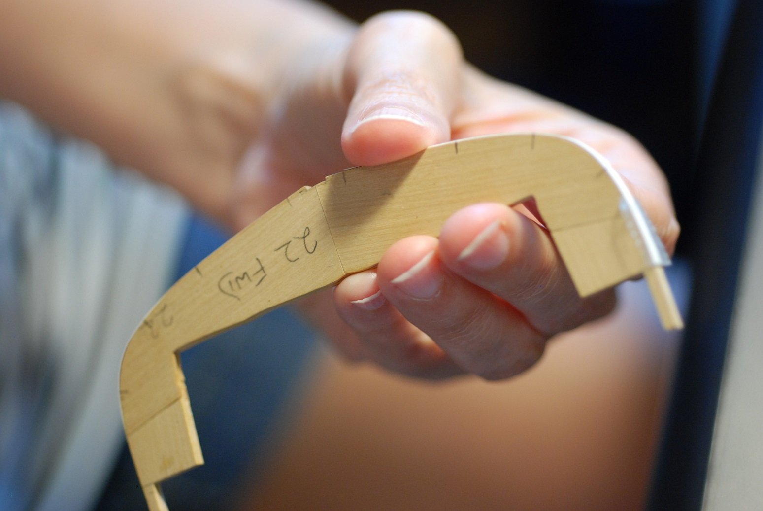
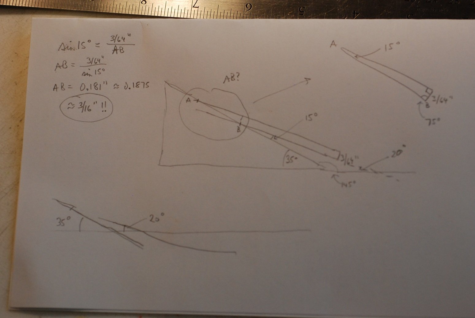
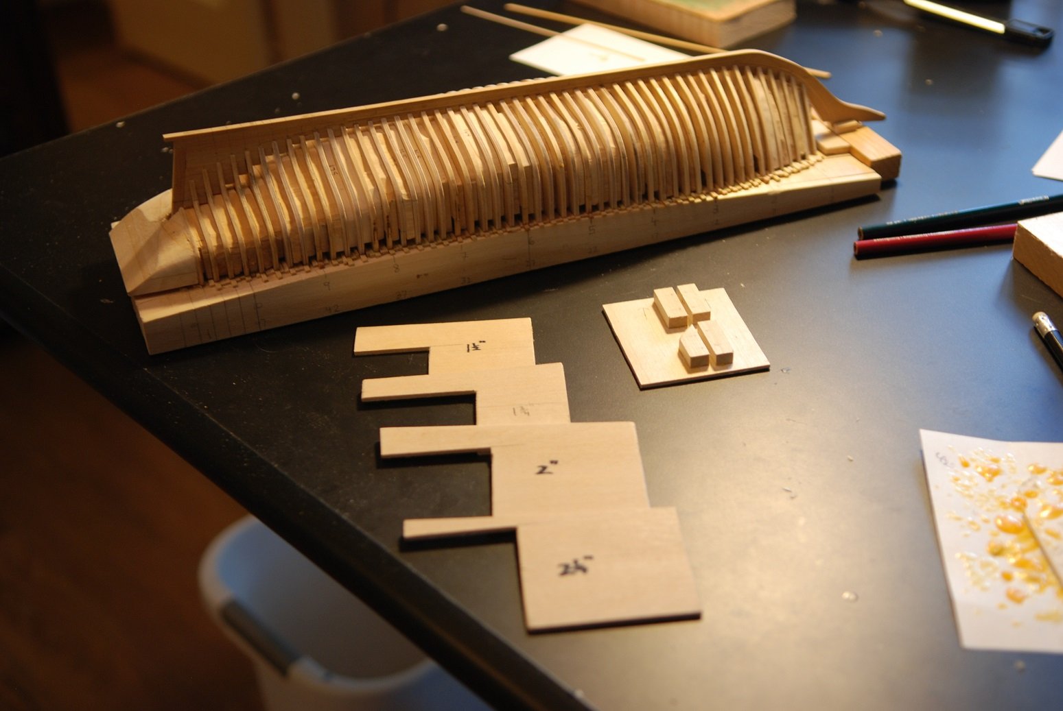
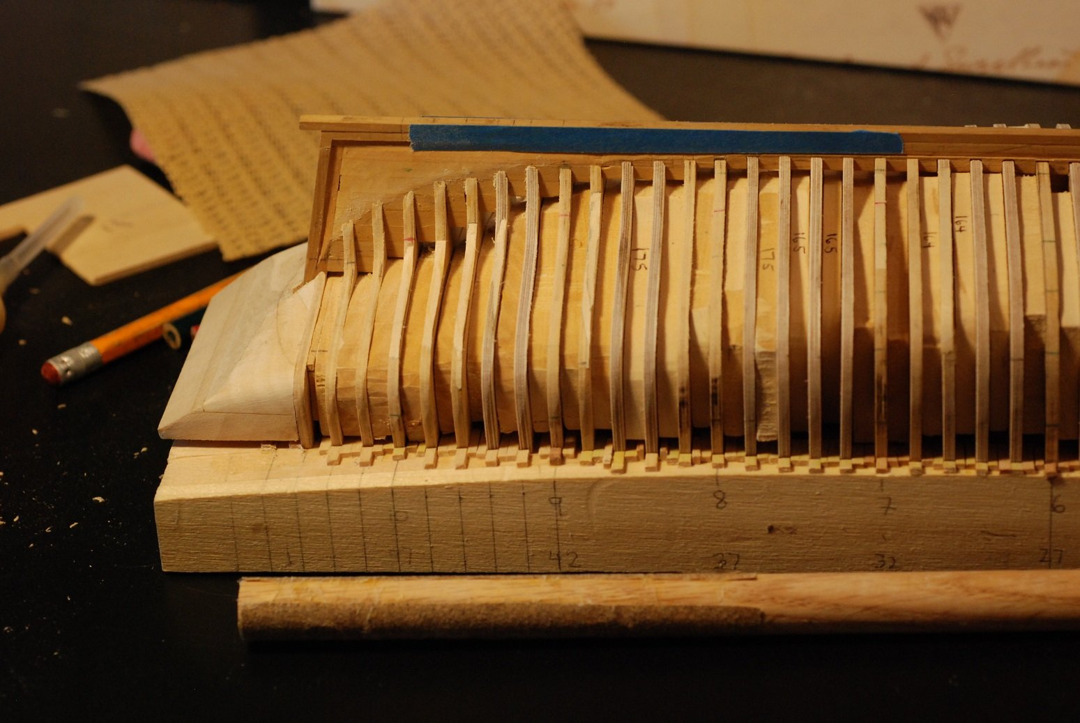
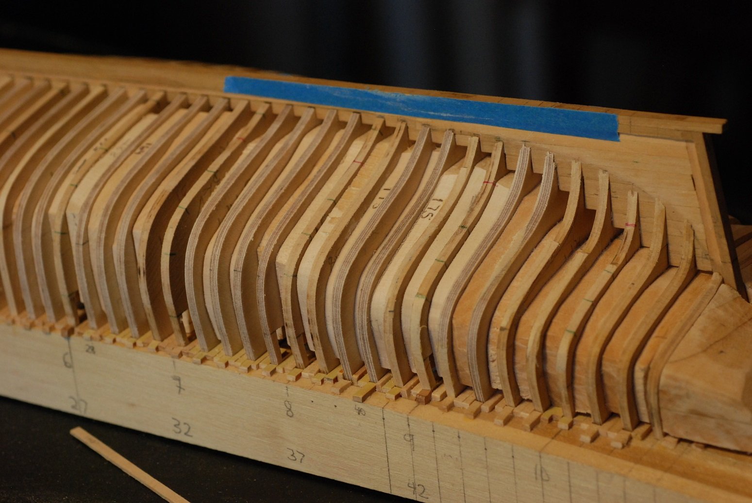
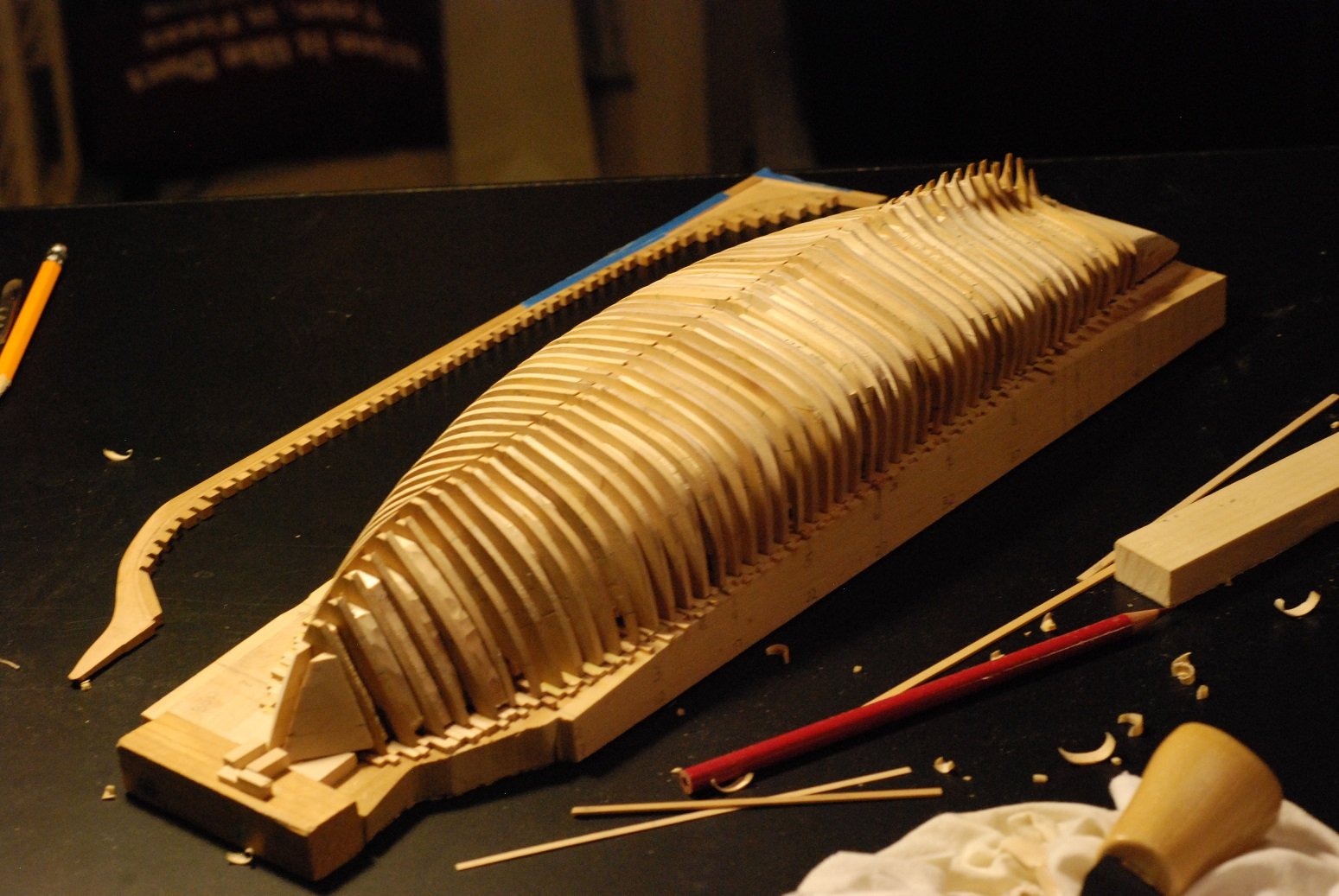
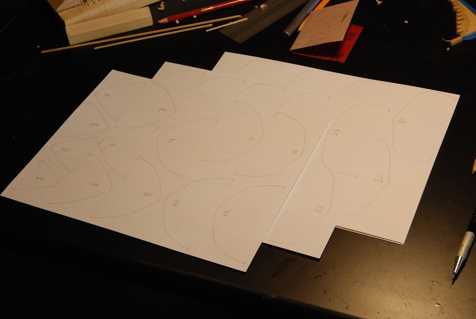
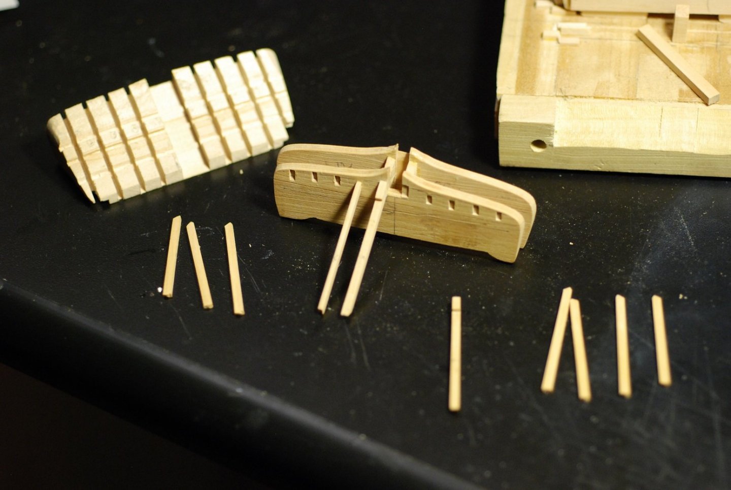
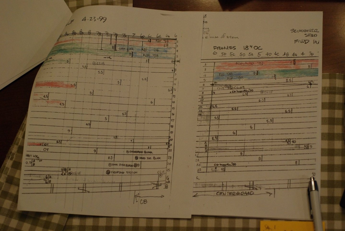
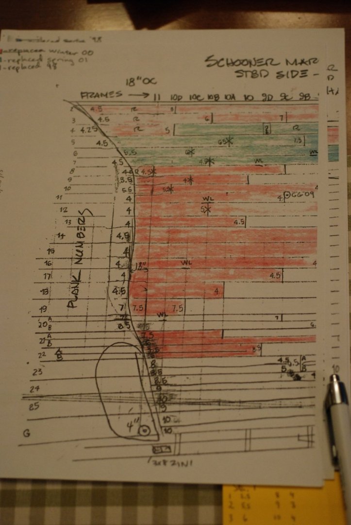
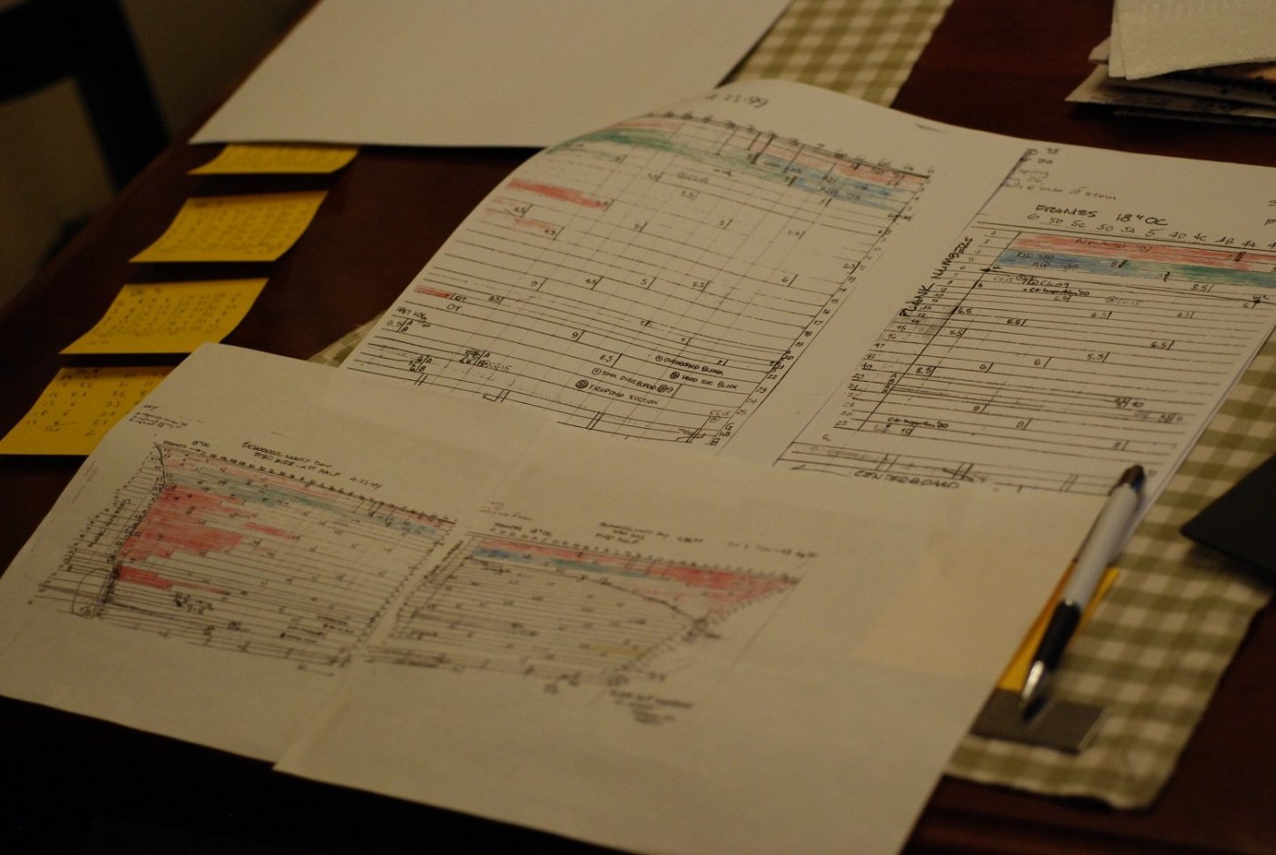
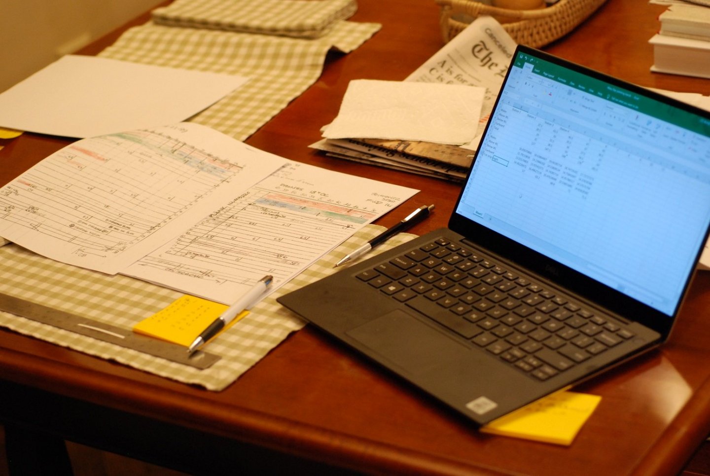
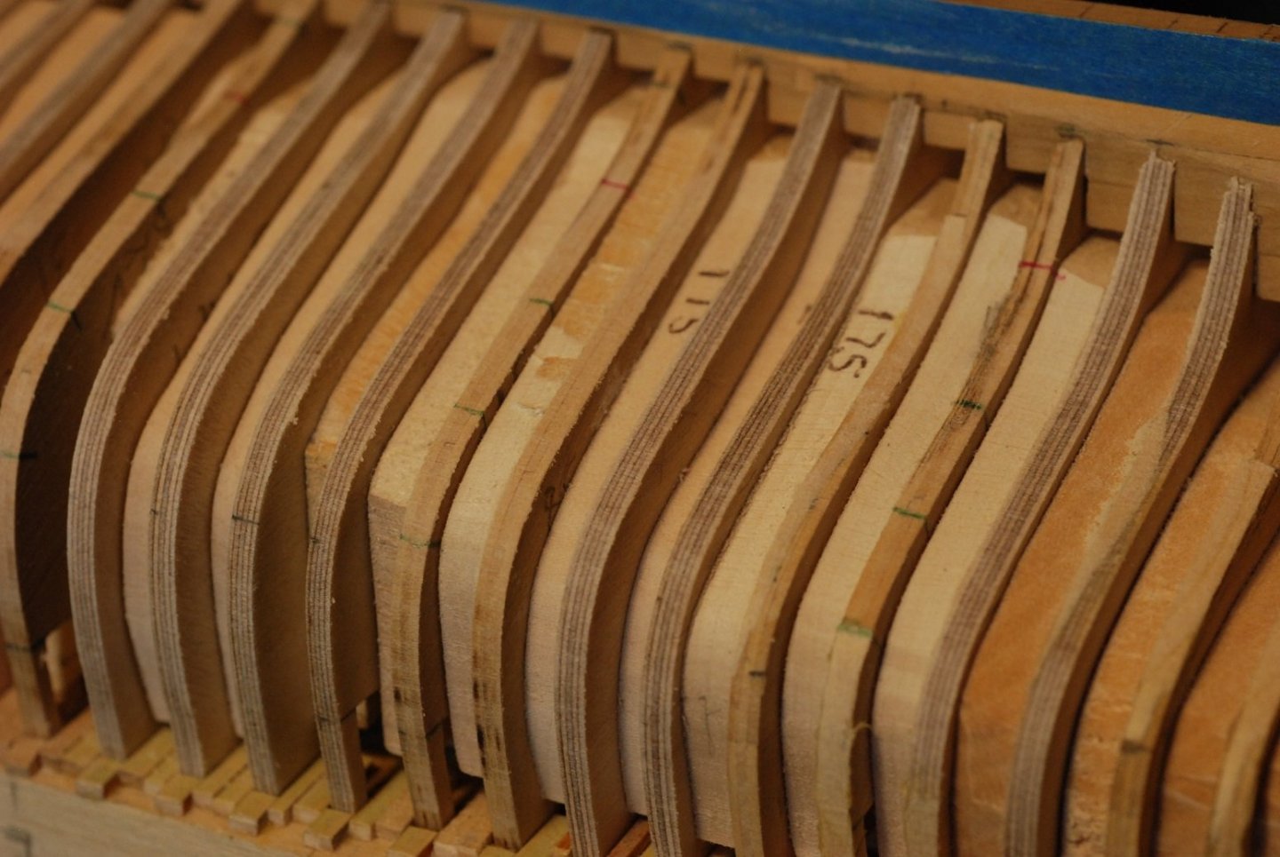
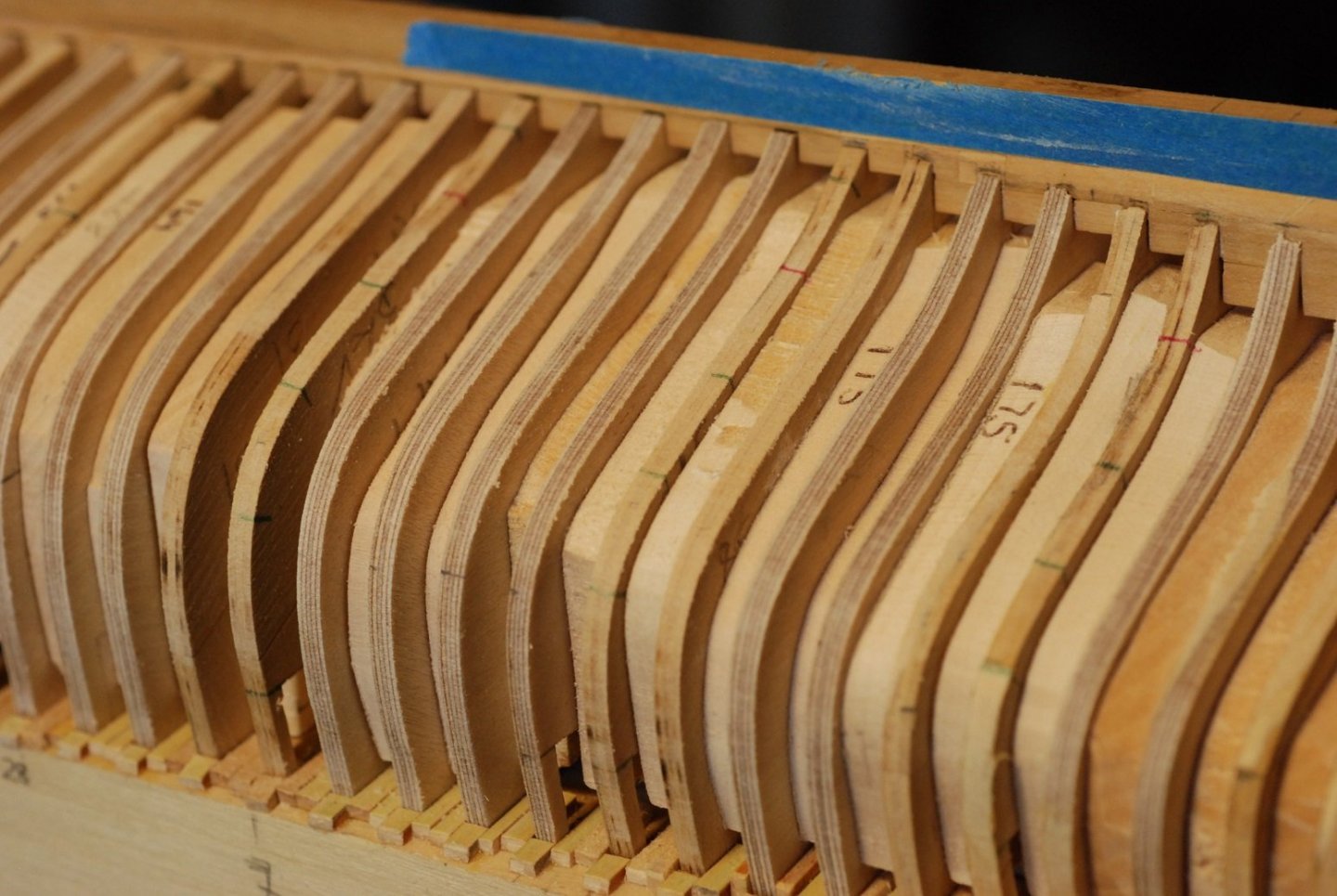
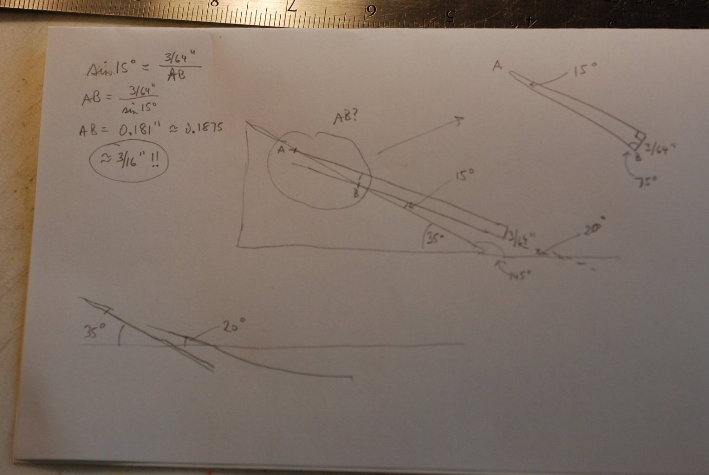
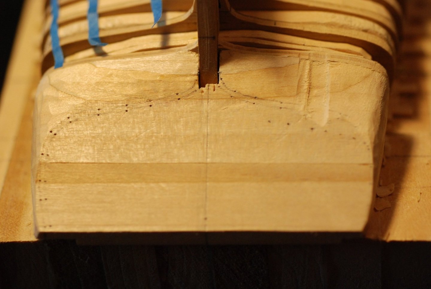
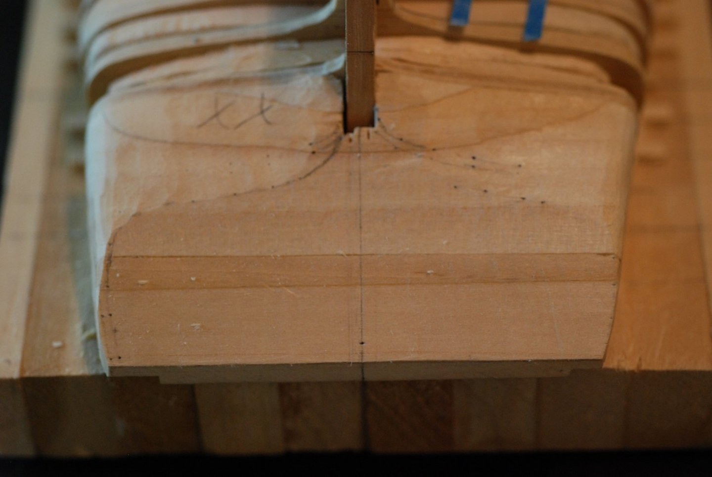
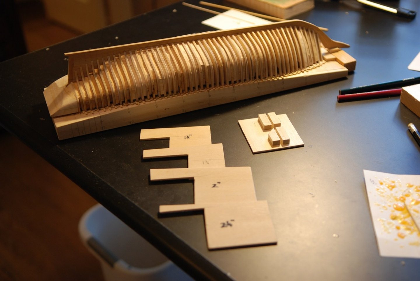
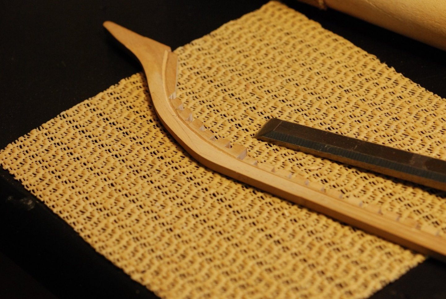
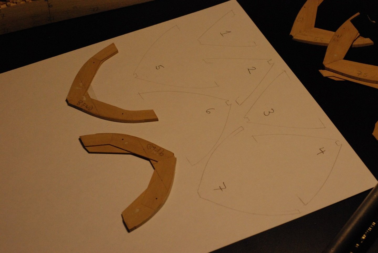
It has been since August that I posted on any model work. I have indeed been distracted by projects related to the new sailboat, but other things were going on, like COVID 19 working its way through our household in December! But work on the model has been occurring, relating to planking prep and construction of the transom. The transom work is particularly interesting and challenging. I hope to do a couple of posts in relatively rapid succession to bring things up to speed. This is an example of how lucky I am when it comes to the documentation of my subject. Cap’n Barry gave me a shell diagram to the Mary Day that lays out the planking on each side of the hull. He explained that each plank’s age is tracked because at any time the Coast Guard can ask for a sample of a particular plank. I suppose that means they take a core sample, then fill the hole with the equivalent of a treenail. Their shell diagram keeps track of when particular planks have been replaced and where samples have been taken in the past. For our purposes, the width of each plank is documented with respect to where the plank crosses a particular frame. I bring this up at this stage of the build because I need to be able to visualize how the planking bands lie, particularly as the bands approach the transom, so I can properly fair the frames (and stern filler blocks, if I end up using them). Also included, but not shown here, is a planking diagram of the transom. The first step of the process was to take each of the 3 sheets depicting the shell diagram and merge them into one image. At each major station location, the width of all the planks was totaled and used for the denominator, then the widths of the planks within a band were totaled. The length of the tick strips was determined by the length on the model from the rabbet to the level of the bottom of the covering board, which is effectively where the hull planking meets the level of the deck planking. The tick strips were then divided according to the relative widths of the planking bands. Marks from the tick strip are transferred to each frame so that despite fairing the frames, the placement of the bands will still be evident. The lovely wife serving as my hand model for this picture. I have marked the edges of the planking bands with red or green marks. These will of course get obliterated as I do more fairing, but they can be restored after that is finished. I started with four planking bands, marked in green, but realized that as you approach the stern, I needed to add a band to cover all the additional territory that opens up. That is marked in red. So the tape gives me a sense of how the planks approach the transom. Portions of the transom filler block have been carved away on each side. I was told there would be no math. But I needed to know more about where the planks land on the transom, and how much I would have to rebate the filler block for the hull planking and the transom planking to meet at the right point. Using that information, I drew a new curve on the transom that was set back the appropriate distance (3/16” maximum) and carved to that curve. This was carried out on the other side. In order to try to keep the shape symmetric, I tried using some creative “feeler gauges” to make sure I was rebating to the same depth on each side. But I ended up just doing it by eye. Back to the rabbet. Here I am checking the depth and angle of the rabbet at a certain frame location with a small piece of wood that is the same thickness as the hull planking, 3/64”. The rabbet was extended in the same way as it would be done at full scale, creating reference points of appropriate angle and depth, which are then connected up. The rabbet has been extended to the start of the deadwood. The rabbet carved into the port side deadwood. And the same for the starboard side. The blue tape prevents scuffing of the keel timber. Before forgetting to do so, I worked on shaping the contour of the stem, which narrows from the full width of 5/32” to a minimum of 1/16”. The narrowing of the keel hasn’t been finished on this picture, but you get the idea. One nice thing I was able to do with the microscope was to achieve a really smooth finish after sanding to 320 and 400 grit by scraping with a razor. I will eventually do that with the rest of the keel, but I have to make sure that fairing is finished first so I don’t accidentally mar the finish. At this point, I feel confident enough about the frame shapes that I wanted to try to preserve them for the future. So I traced out the shape of each frame (larger side of each frame, of course) onto card stock, and scanned them into PDF files. Maybe this will come in handy in the future. So the next post, which will hopefully follow soon, will focus on transom construction. It’s nice to be back at it!


-
You could make a little bucking iron to hold on the outboard surface of the rivet, then use a tiny hammer to peen over the inboard end of the rivet...
-
My wife often refers to our ship-building hobby as a beautiful madness. Speaking of madness, Toni, I hope you aren't going to go to the trouble of installing roves on the inboard (invisible) surface of the hull!
-
I need to look up Wes Marden's booklet. The case that was made for my Pride of Baltimore 2 took altogether too long for the parts to be manufactured by an outside party. Then the glazier I hired to assemble it did a horrible job. My neighbor and I imagine that we could have done a far better and faster job.
-
Congratulations! Now it's time for a cleaning of the shop, followed by opening up the next project... I hope the pandemic resurgence isn't too bad in your area!
- 221 replies
-
- 2
-

-
- queen anne barge
- Syren Ship Model Company
- (and 1 more)
-
Shameless plug for Rockler Woodworking, I see! I am lucky to have one about 3 miles from my house. What an impressive jig! Gonna spend some time looking at that one, because the more time spent, the more I think I can learn from it...
-
I think I see what you are pointing out, so I have taken another photo now that I have begun carving out the rabbet. I haven't extended the rabbet into the sternpost yet. In my previous picture, the keel timber on my model may have appeared deceptively small. The top of the keel timber is indicated on my model and on the plan by the red arrows. My photo doesn't show the details of the keel further forward on the plans or on the model, so I can see how it's easy to lose track of what is where. I got a response back from Skipper Barry King about the position of the rabbet and the sternpost. He said he couldn't remember, mumbling something about how I now seem to know more about the details of his schooner's construction than he does...
-
My colleagues, have a look at this photo and give me your opinion. The portion of the plan showing the sternpost, rudder, and deadwood are presented, and my keel assembly is lying on top of it. I am beginning to work out the rabbet (although this picture does not show the work I have done to this end). The question I have is where the rabbet ends on the sternpost. I think that the dotted line traveling nearly vertically along the sternpost represents the end of the rabbet and the end of the counter planking. Right? Is there any reason to suspect that the planking should instead end where the sterpost and the deadwood meet? Any reason to suspect that the planking would travel further aft than the dotted line? Certainly the end grain of the planking should not be exposed, as it would be if the planking extended to the aft surface of the sternpost. Thanks in advance for any input.
-
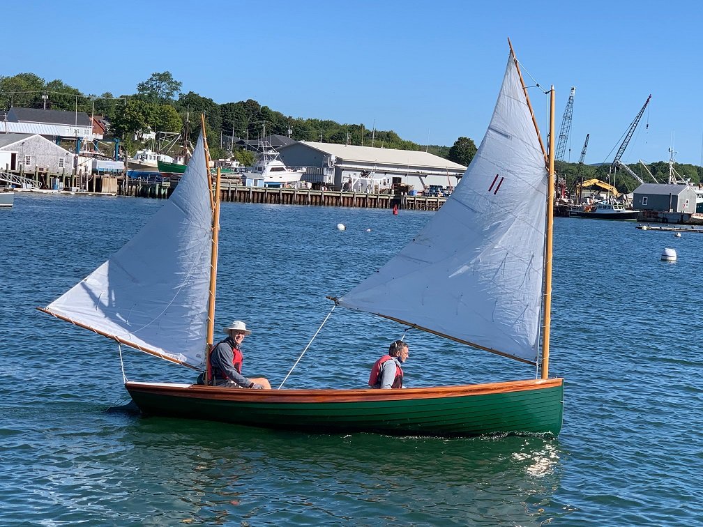
She is a Nat Herreshoff-designed "Coquina". Fans of Wooden Boat magazine may remember a recent issue that included an article about the DN Hylan boatshop on the coast of Maine, who offer a kit for the Coquina, or you can commission them to build one for you. JD
-
I have a confession to make. Last week I was back in Maine, taking more measurements from the Mary Day while she is cooped up in Camden, waiting out this tourist season that has been cancelled due to COVID-19. Down the road from Camden, in Rockland, is the Apprenticeshop, which is a school for apprenticing individuals into the traditional skills of boatbuilding. (apprenticeshop.org) They had this boat for sale...and I bought it! As if I needed a distraction from my model building efforts! She will make the journey from Maine to Texas next week, and hopefully will be here in time for the weekend of Sept 12-13. It really wasn't as spontaneous a buy as I make it sound. I have had my eyes on this boat since about this past January, when I learned about her design and then found an example for sale. This was just my first opportunity to make it back up to Maine since the pandemic started. Anyone who can tell me the name of this design will win...my undying respect!
-
Druxey, I will give your cure for pin marks a try!