HOLIDAY DONATION DRIVE - SUPPORT MSW - DO YOUR PART TO KEEP THIS GREAT FORUM GOING! (Only 13 donations so far - C'mon guys!)
×


jdbondy
-
Posts
340 -
Joined
-
Last visited
Content Type
Profiles
Forums
Gallery
Events
Everything posted by jdbondy
-
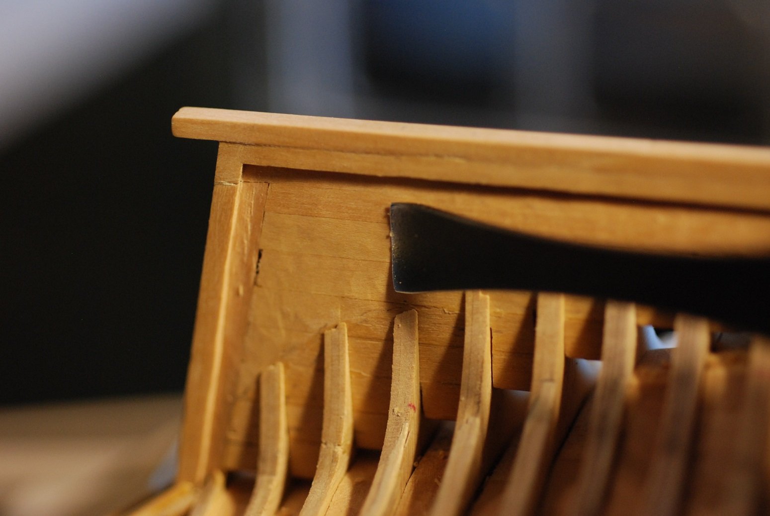
 Thanks, John. Yes, that overhang has already been trimmed down flush to the sternpost and it looks much better.
 -
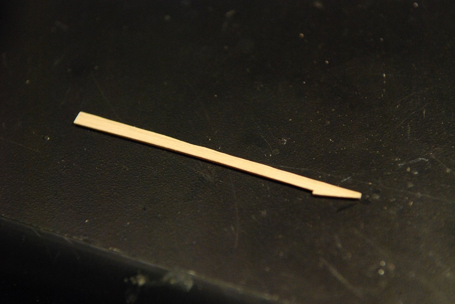
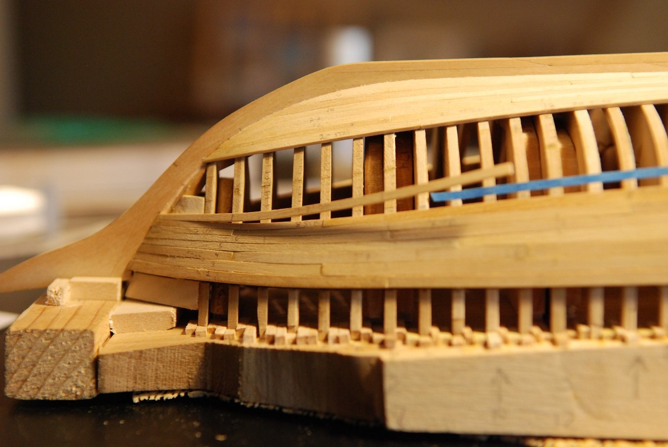
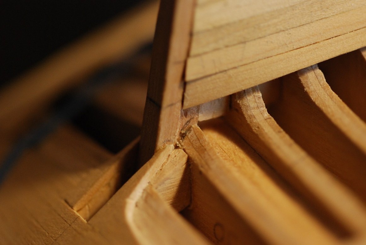
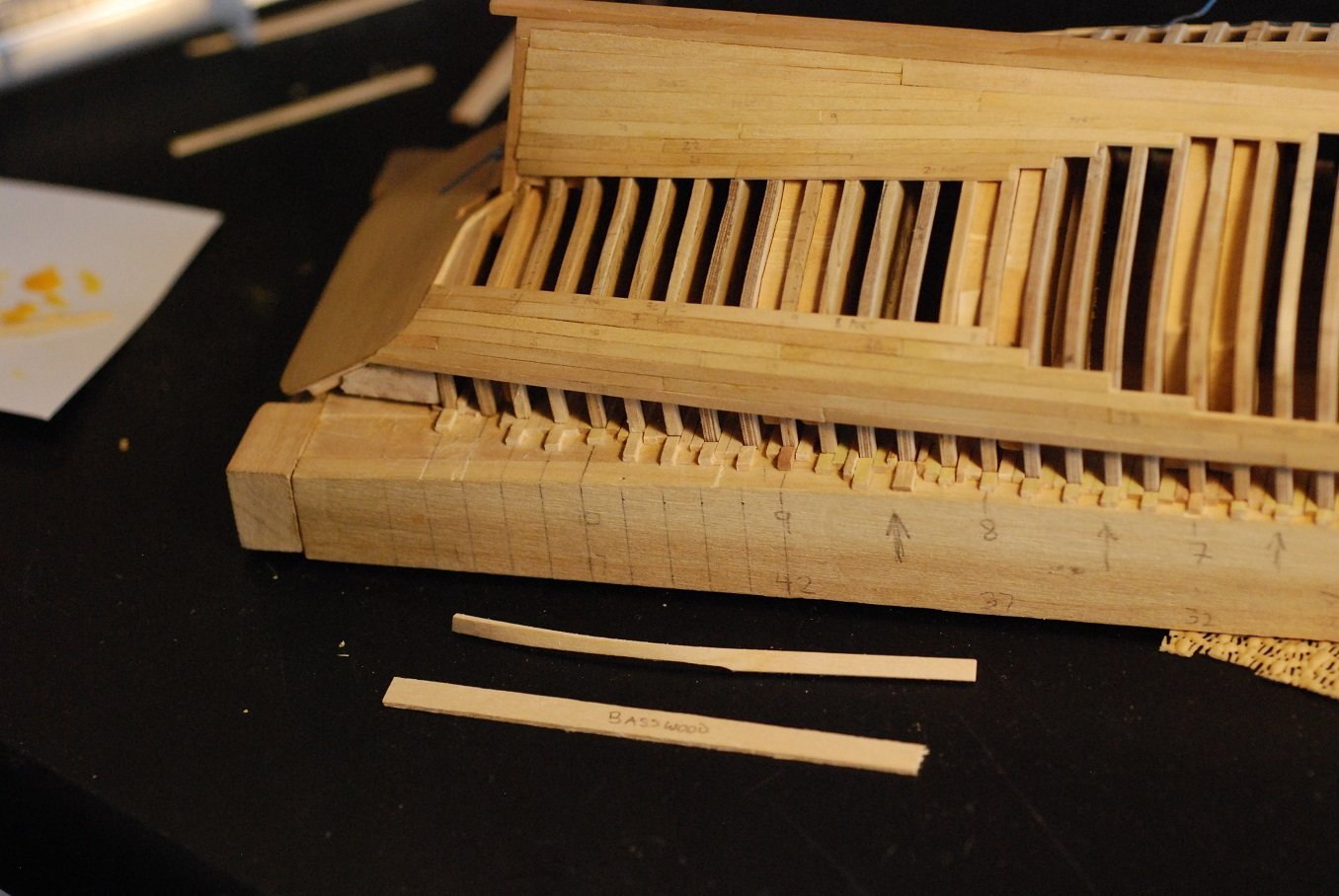
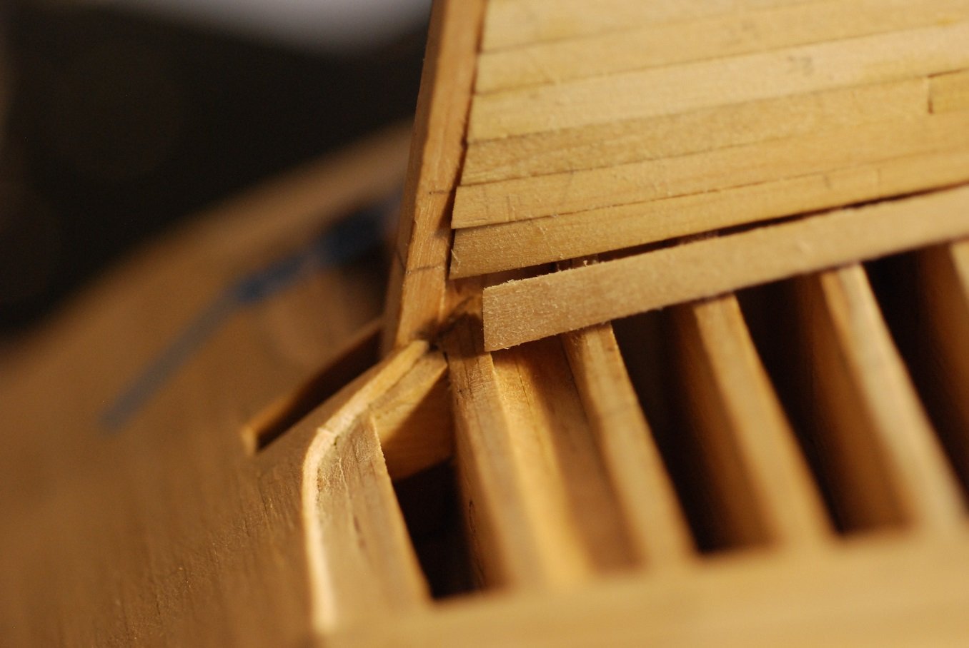
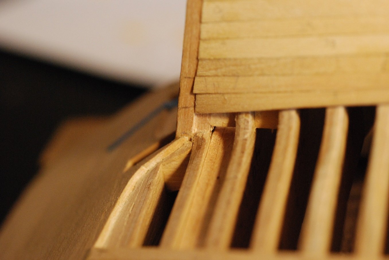
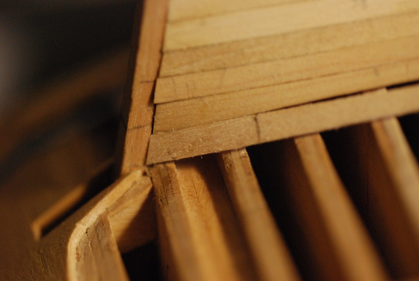
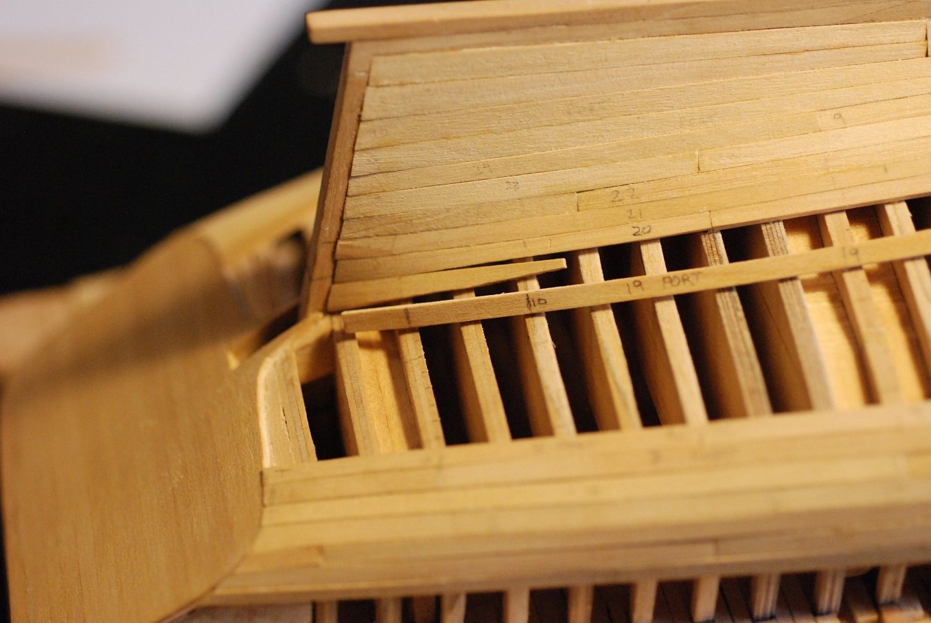
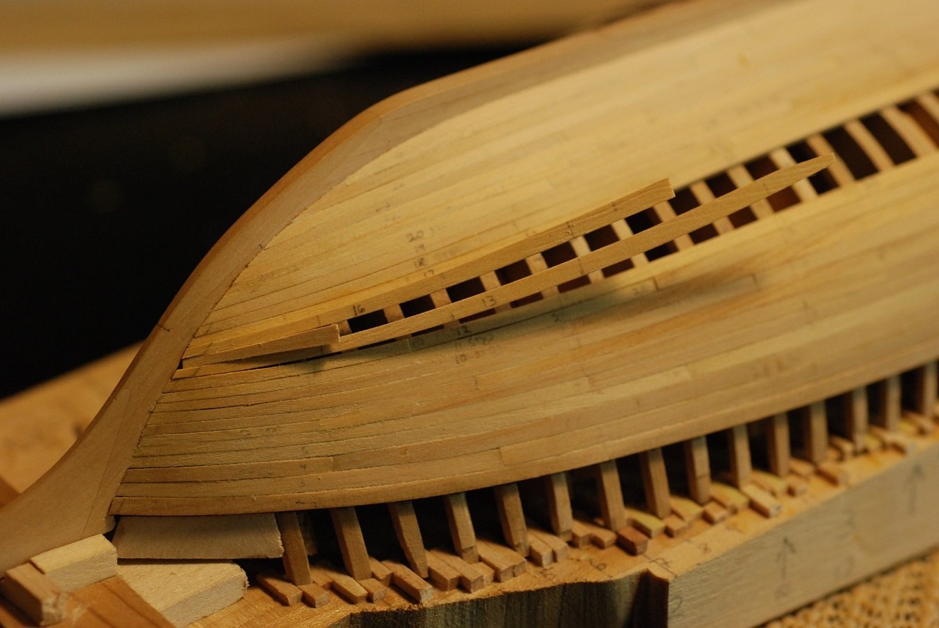
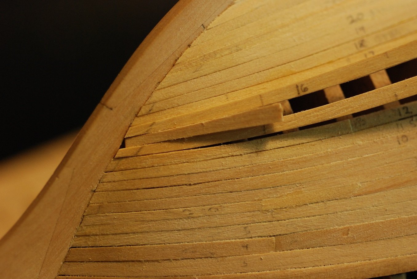
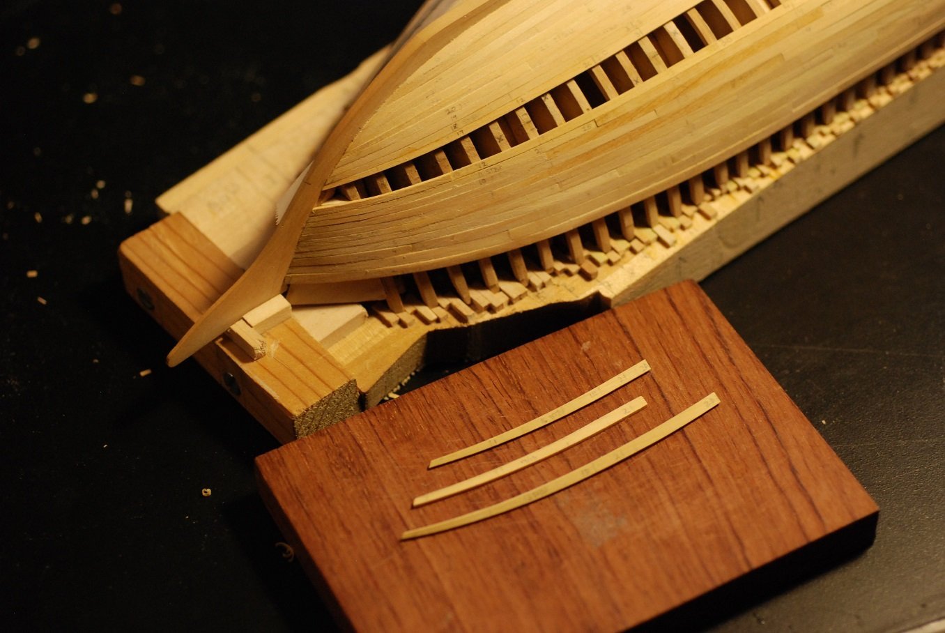
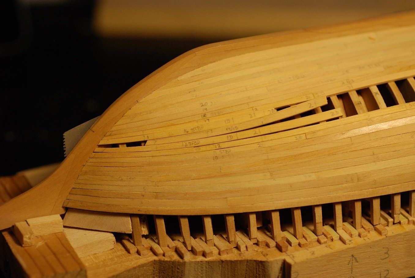
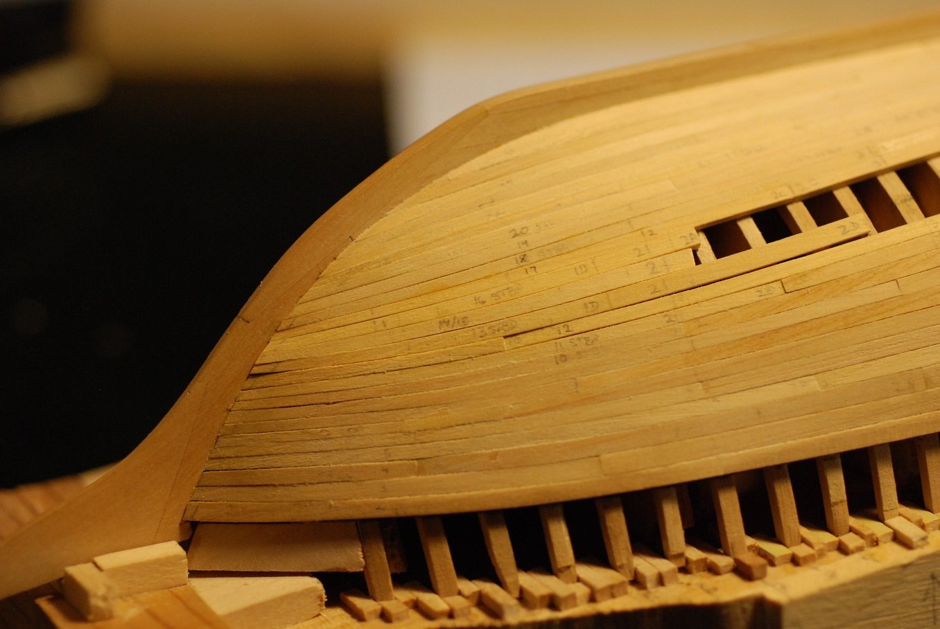
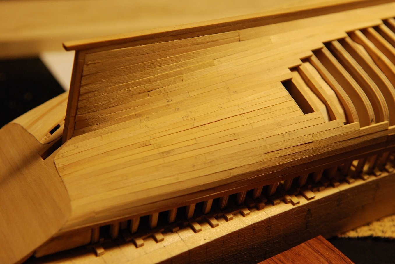
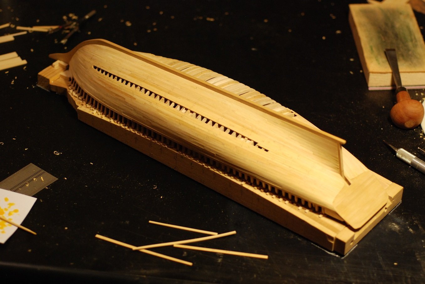
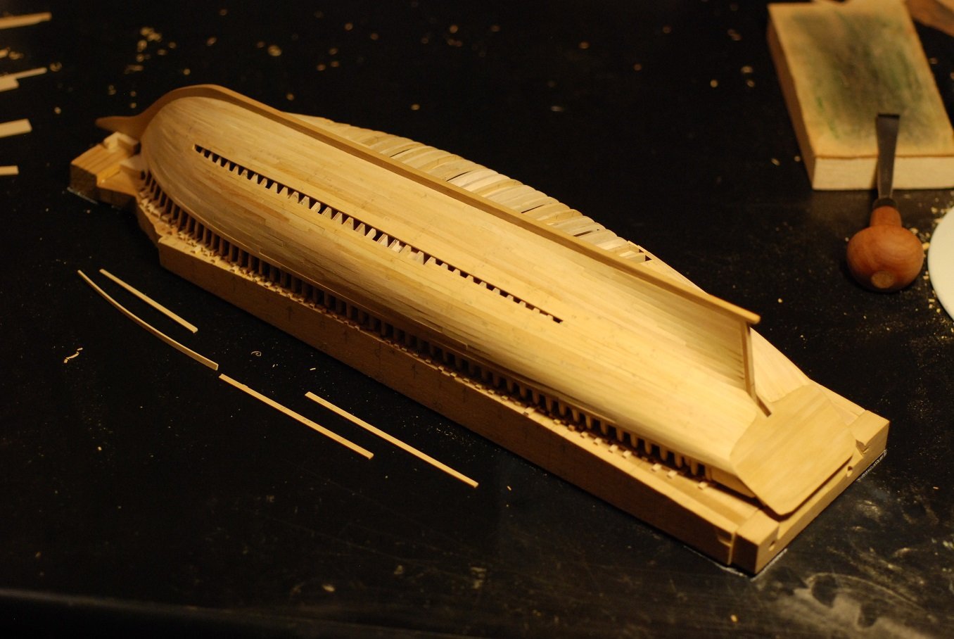
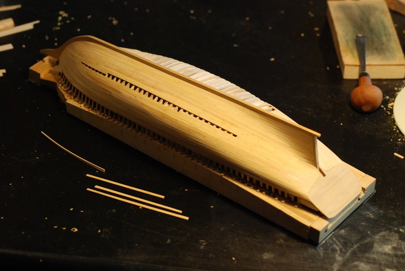
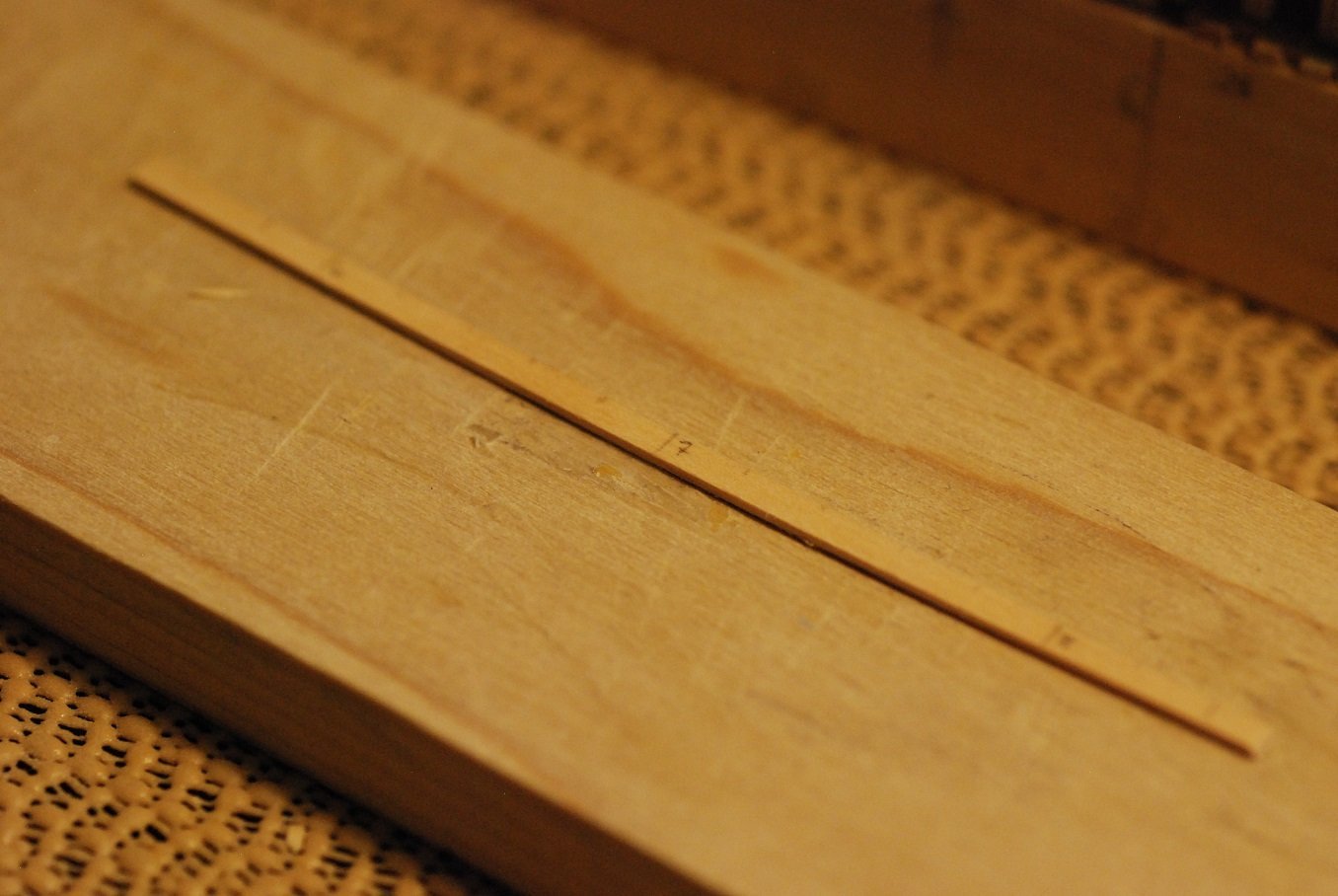
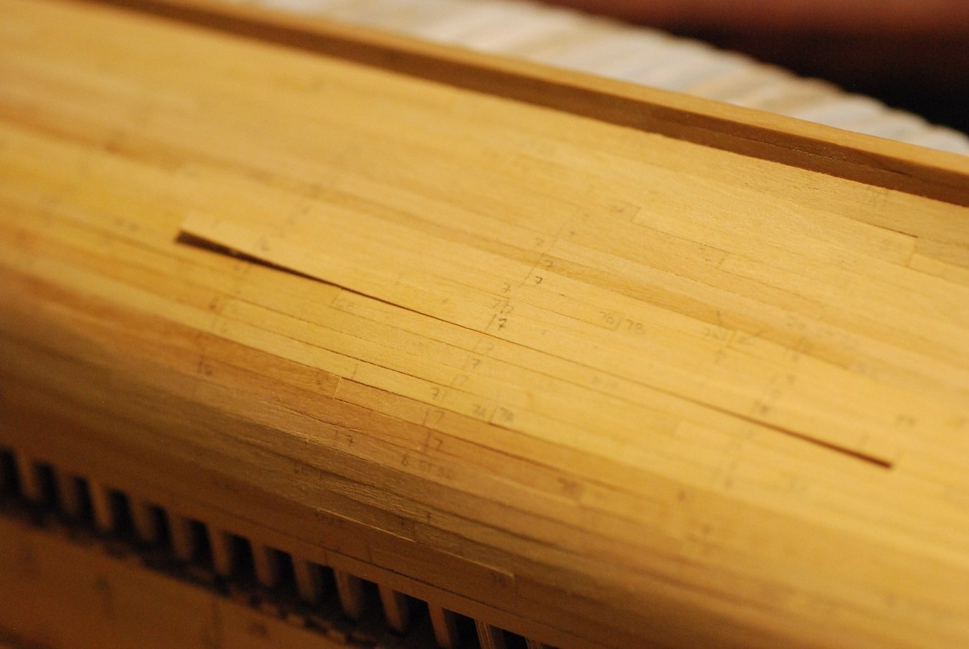
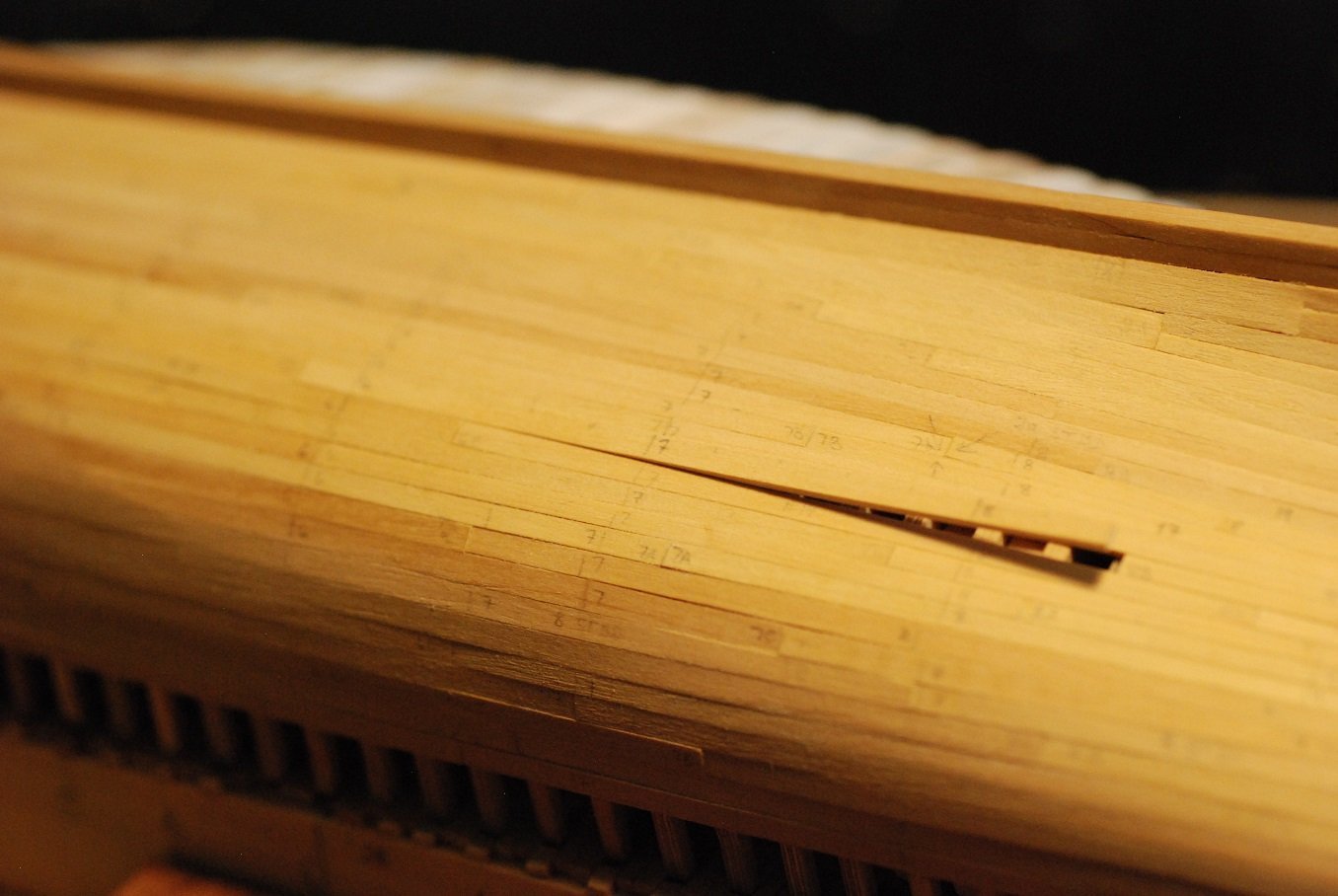
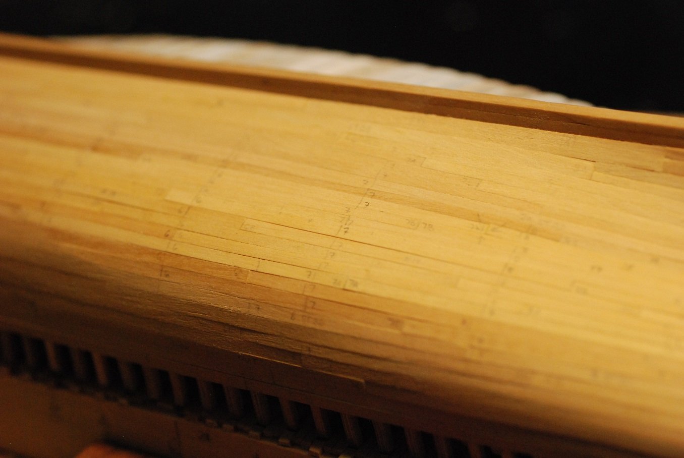
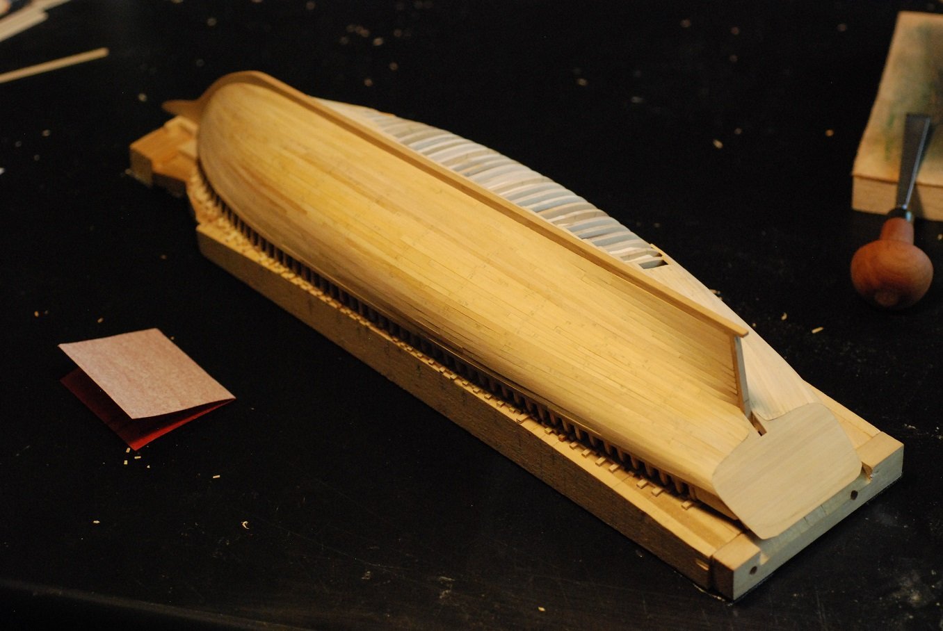
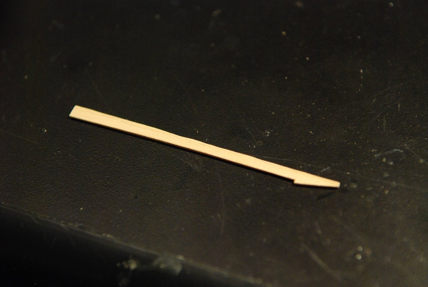
I finished the hull planking on May 3, about 2 months later than I had wanted to finish it. Life just gets in the way sometimes. As of the last post, I estimated I was halfway through the planking. It was time to rip more lumber for the build. I try to take a photo when I rip more planking, so that hopefully I can go back afterward and estimate how much I really ended up needing. The planking stock is Castello boxwood. It has been a pleasure to work with. This will mostly be a pictorial essay, but I will add some commentary at certain points. The junction of the sternpost and the transom was tricky. I had to do a lot of fine carving to remove enough underlying wood to get the planks to lie down right. I used some basswood to create a feeler plank that guided how much wood needed to be removed. At this point I created a short strip that could be temporarily fixed adjacent to the sternpost, so that I could work on the next plank up, which ends adjacent to the lowest portion of the transom. There is a planking seam very close to the sternpost, which was nice. I was able to create this very short planking segment, which was easily tunable to make sure things were right. The next portion of this plank is temporarily fastened in so that the next plank can be worked on before gluing in this one. I haven’t been able to examine the real transom on the real ship to see how this planking looks. This first plank that ends against the transom gets pretty wide at its end, and that may not be the way it looks in reality. But it’s time to move on to the bow. This band of planking consists of four planks, but it was necessary to drop one plank toward the bow. So the space at the stem was divided among three planks. Sizing up the three planks, gradually reducing the size of each so as to end up with three of similar width. Turned out pretty well. Time for more lumber. This bump is a short segment of wood to fill in a dip that occurred when I applied a plank butt to a frame that was a little small. It was sanded down flush. The bow portion of the port side is finished; just a few more stern planks to go. All done on the port side. Next is a series of photos showing the closing up of the starboard side. Down to the whiskey plank. I had a plank ready to go, but it was just a little off. So I made a new one. Whiskey all around for the building crew! No time to rest on laurels, though. There is plenty of cleanup to be done before I can move on, so I will probably do another post showing the things that need to be straightened up with the planking before working out the interior structure.
-
HMS EURYALUS by Matiz - FINISHED - scale 1:56
jdbondy replied to matiz's topic in - Build logs for subjects built 1801 - 1850
Wow. Guess I just gotta keep on learnin'. JD -
HMS EURYALUS by Matiz - FINISHED - scale 1:56
jdbondy replied to matiz's topic in - Build logs for subjects built 1801 - 1850
Look at you two, showing off your fancy nautical terminology! Are the hammock battens the sawtooth things that look like they are for making a grating? -
Since I am in the midst of doing this right now on my model, I thought I would describe my individual situation. I am using thin (3/32") strips of Castello boxwood for my current planking project. I soak them for 10 minutes, then wipe off the excess. I then hold it in the heat from the hair dryer with my hands, which helps me judge if I am too close or too far. I watch the moisture evaporate off the wood, then test fit the plank. Then I still have time to go back to the hair dryer for some more bending force and heat if it is needed. This has been enough for my situation to get the plank close enough to where it can be glued in place...after I leave it to dry overnight so I am not gluing down a swollen plank.
-
Wow...
-
Hi Mike, congratulations on finalizing the transaction! I am so relieved that you have stepped forward. Next for me is to go register at seawatchbooks.com!
-
Mark that is a really robust-looking setup. I am going to keep that in mind when it comes time for me to cut moldings. Thanks!
-
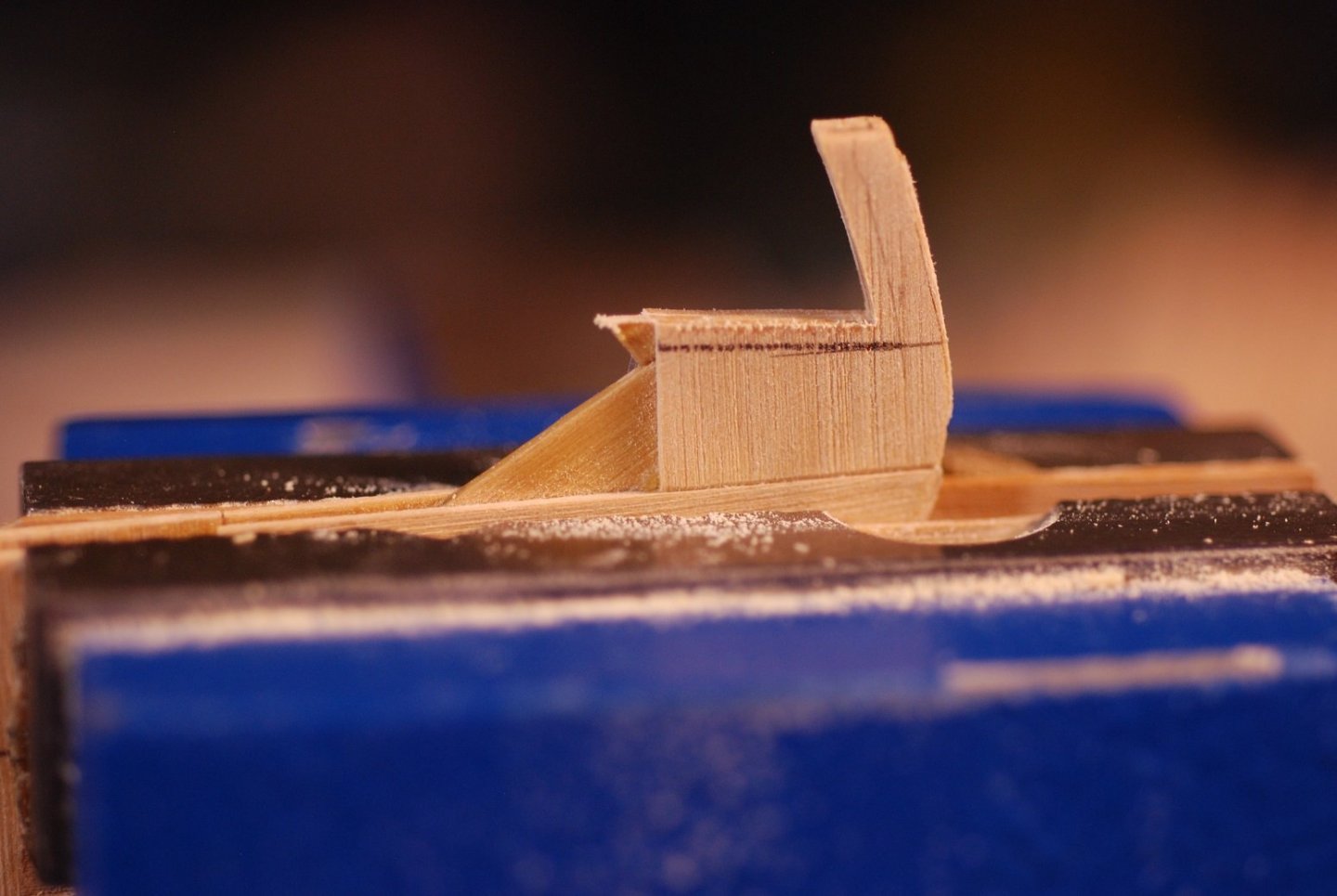
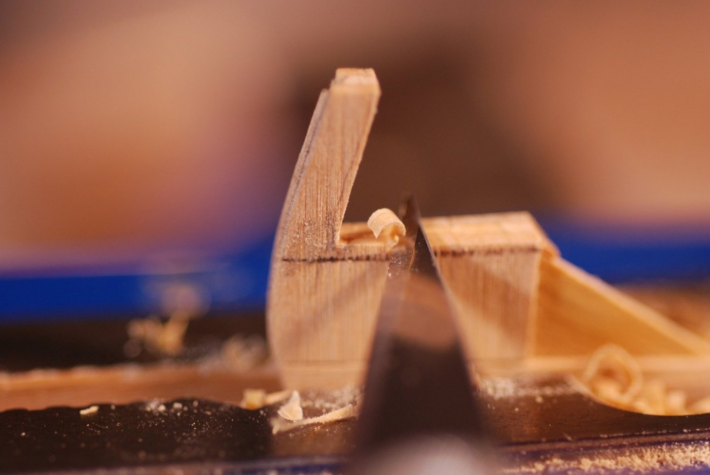
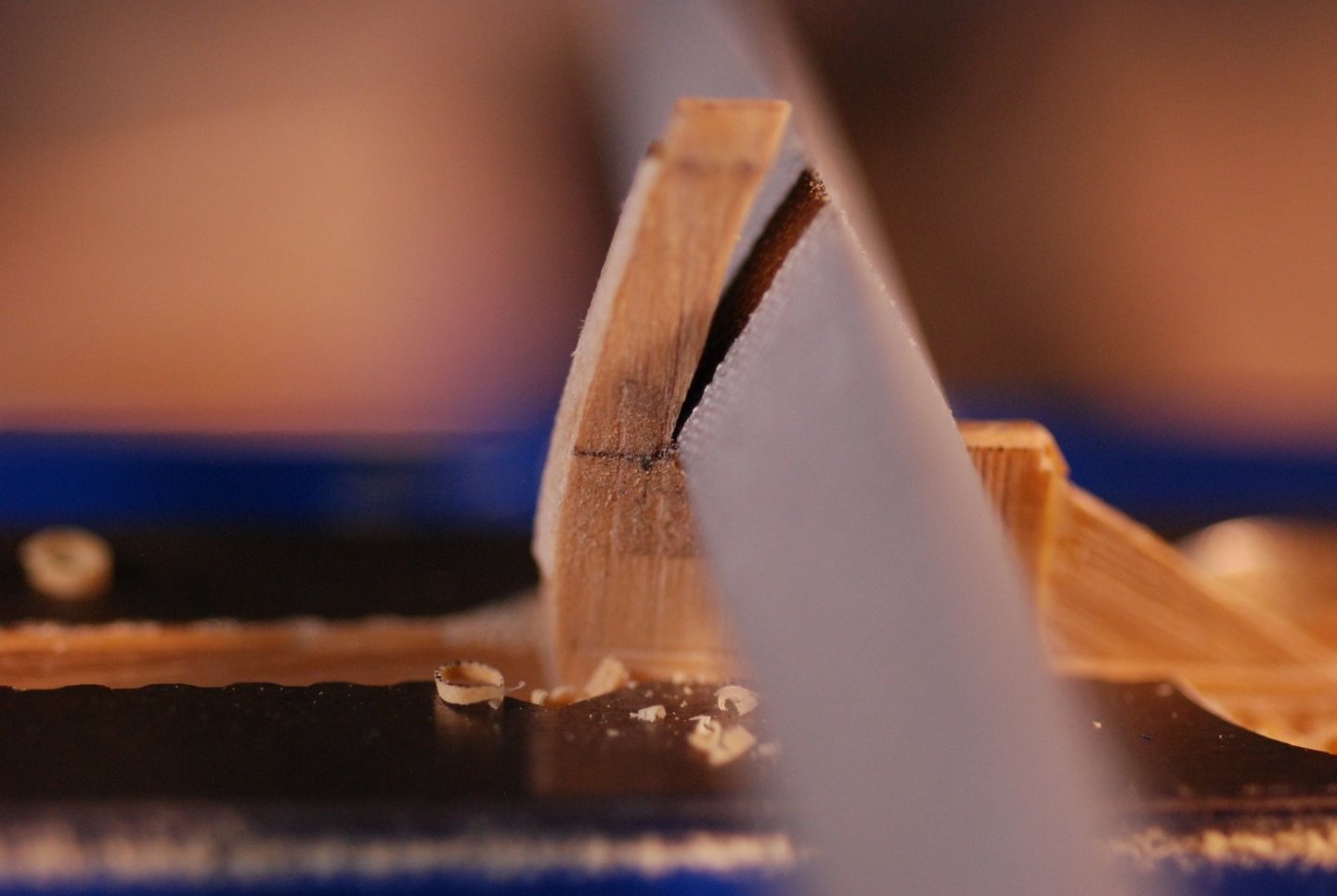
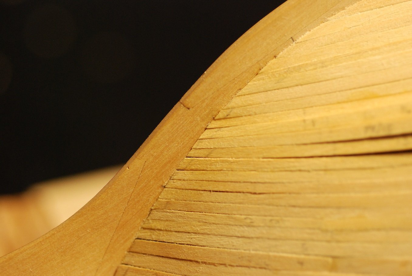
Beautiful macro images!
-
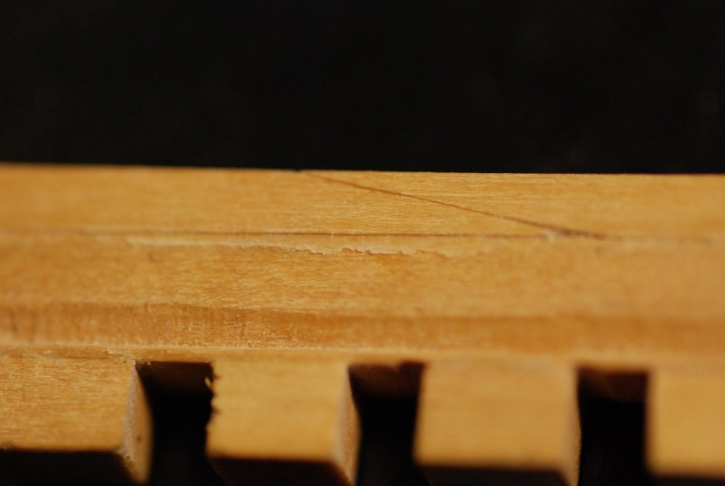
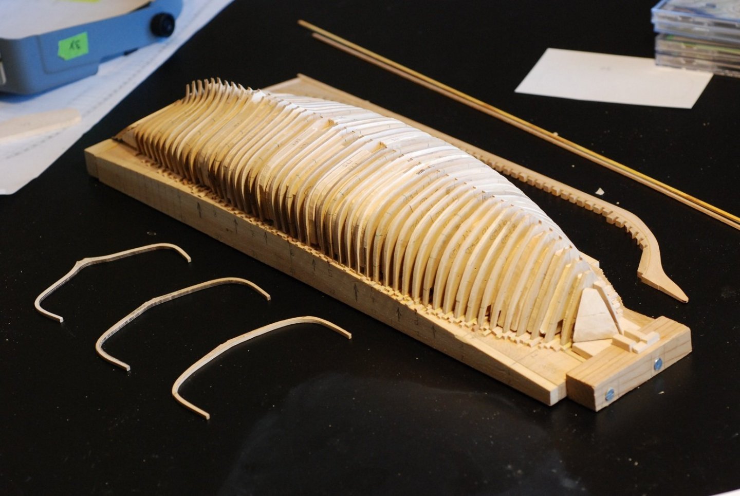
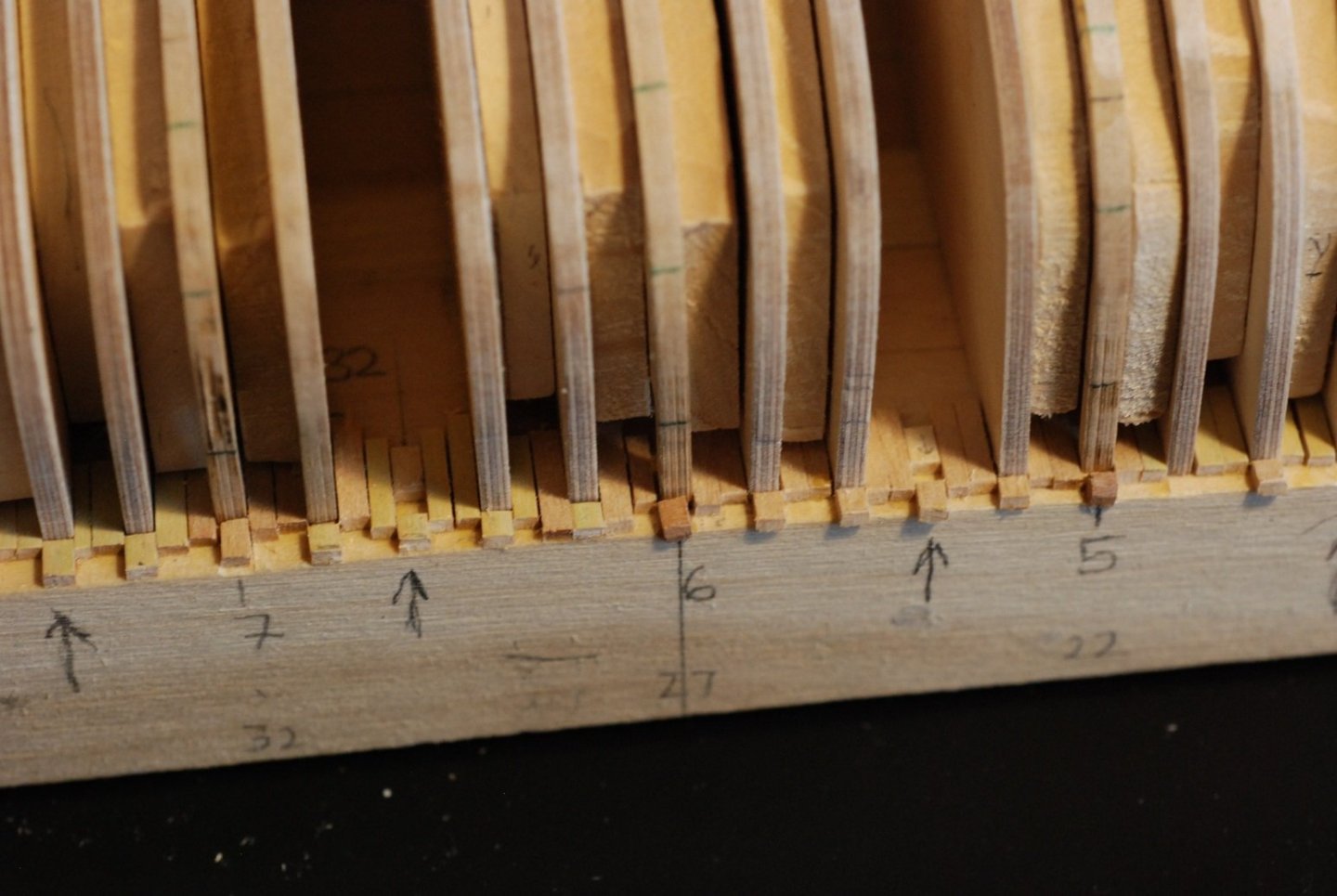
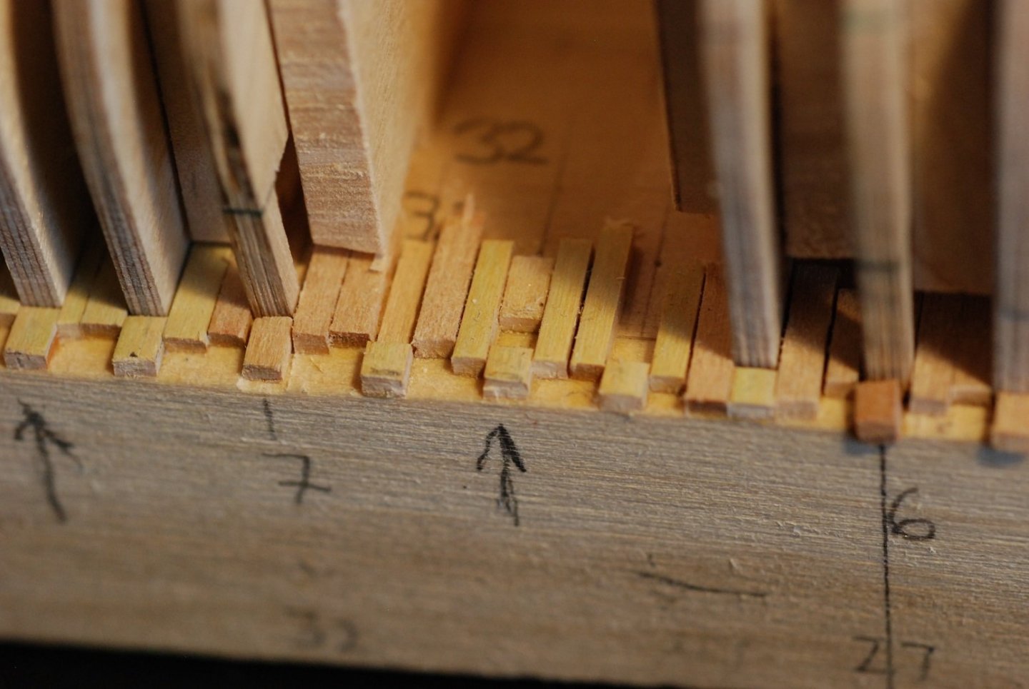
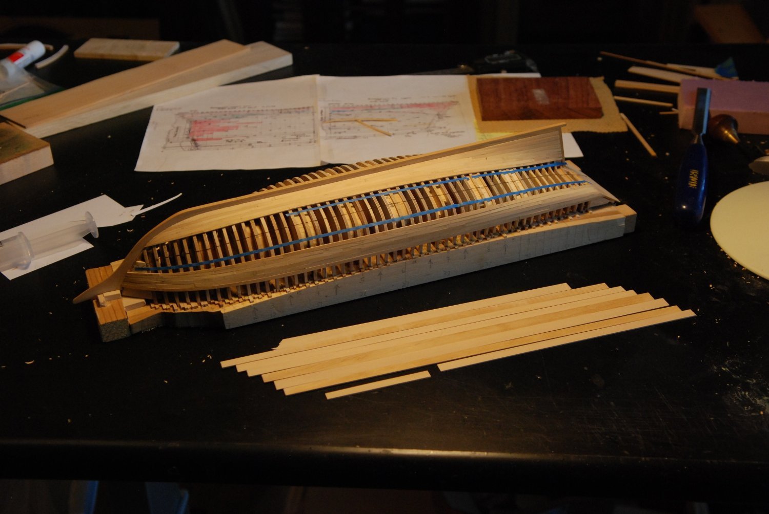
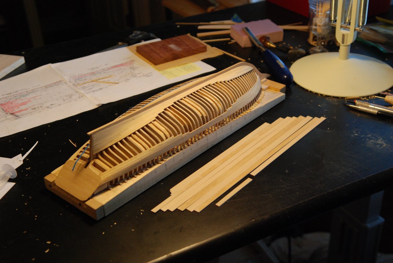
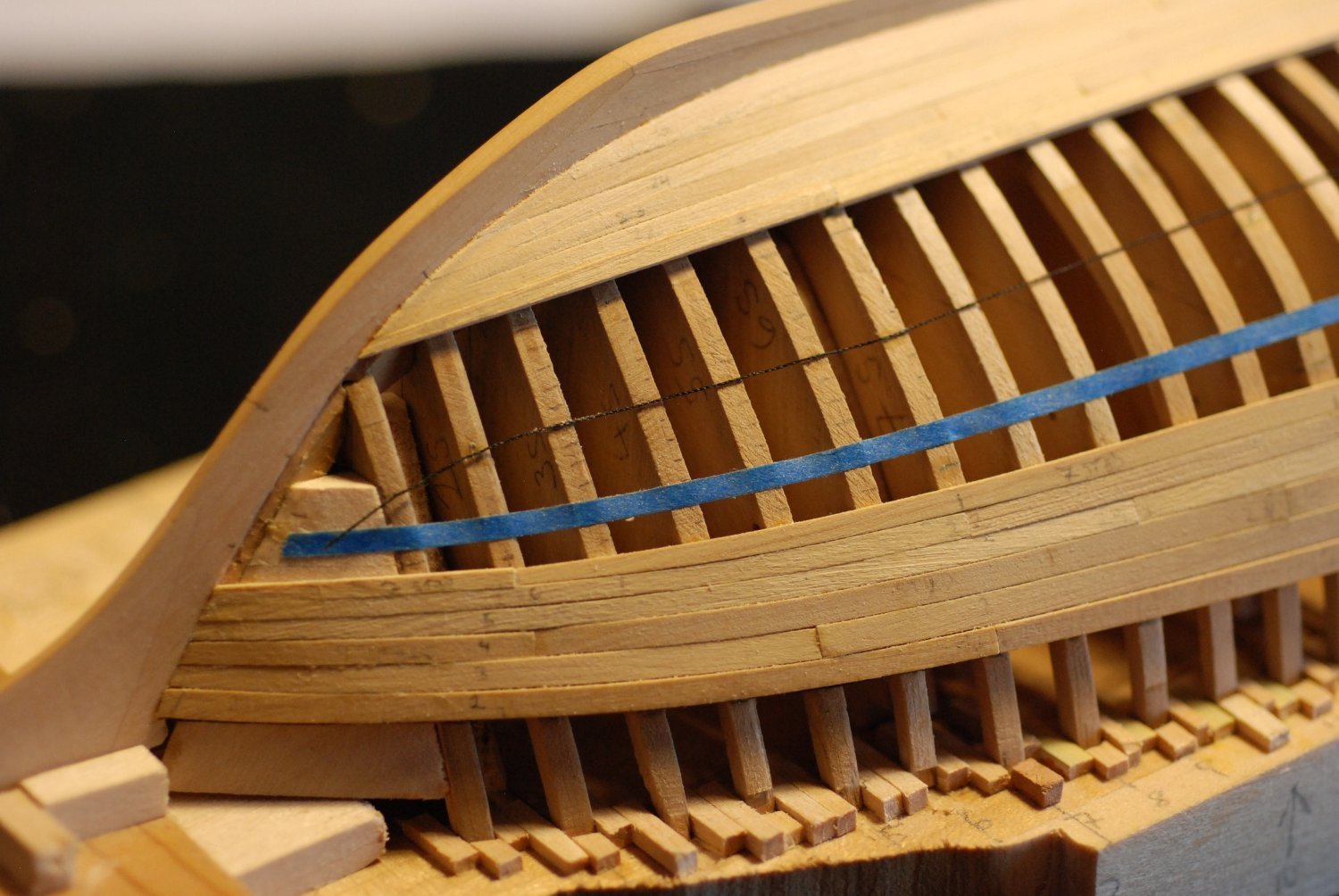
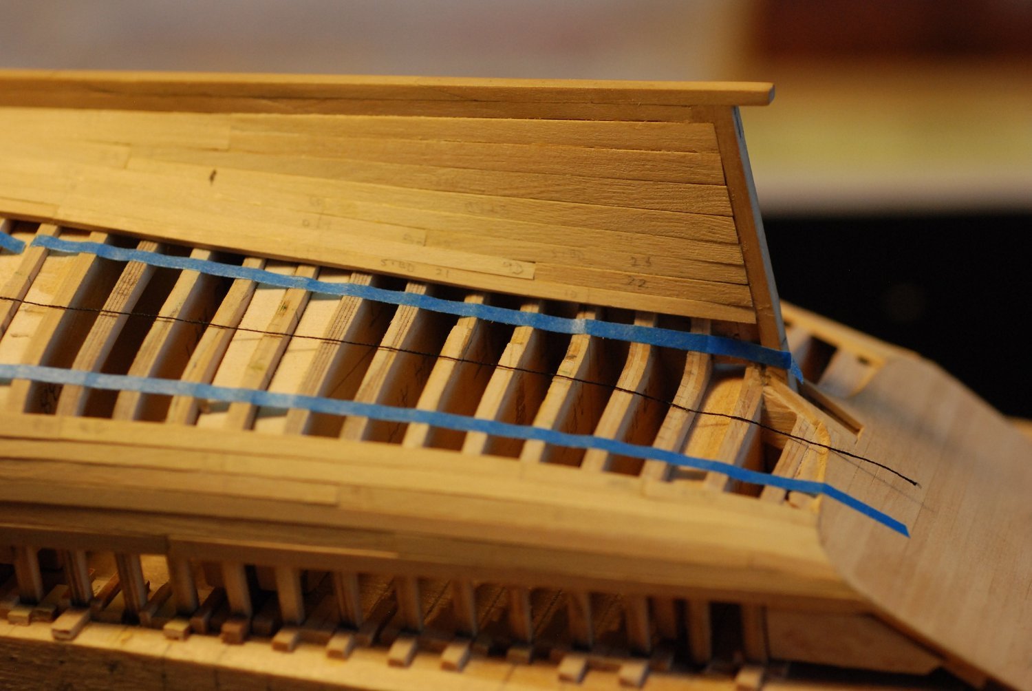
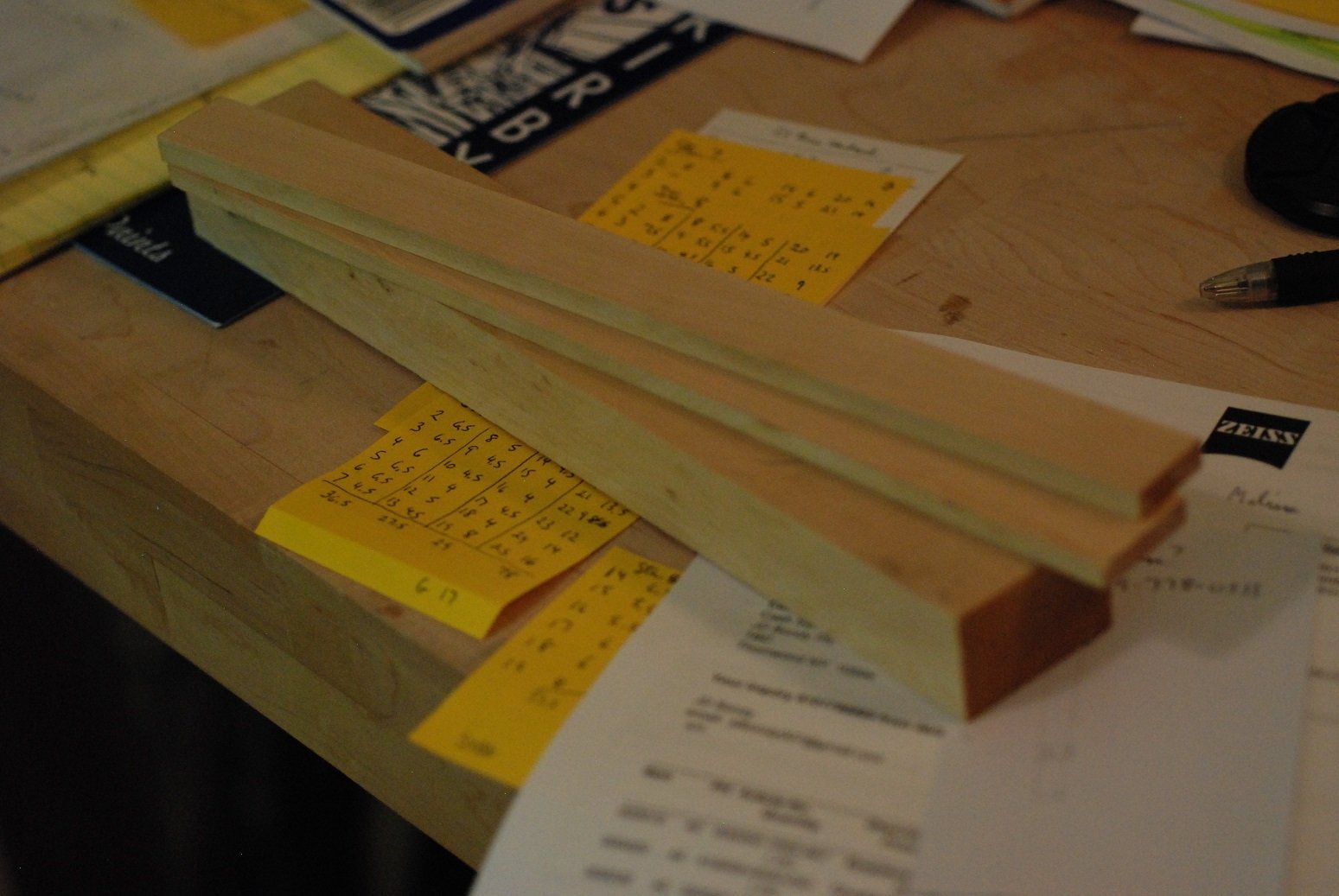
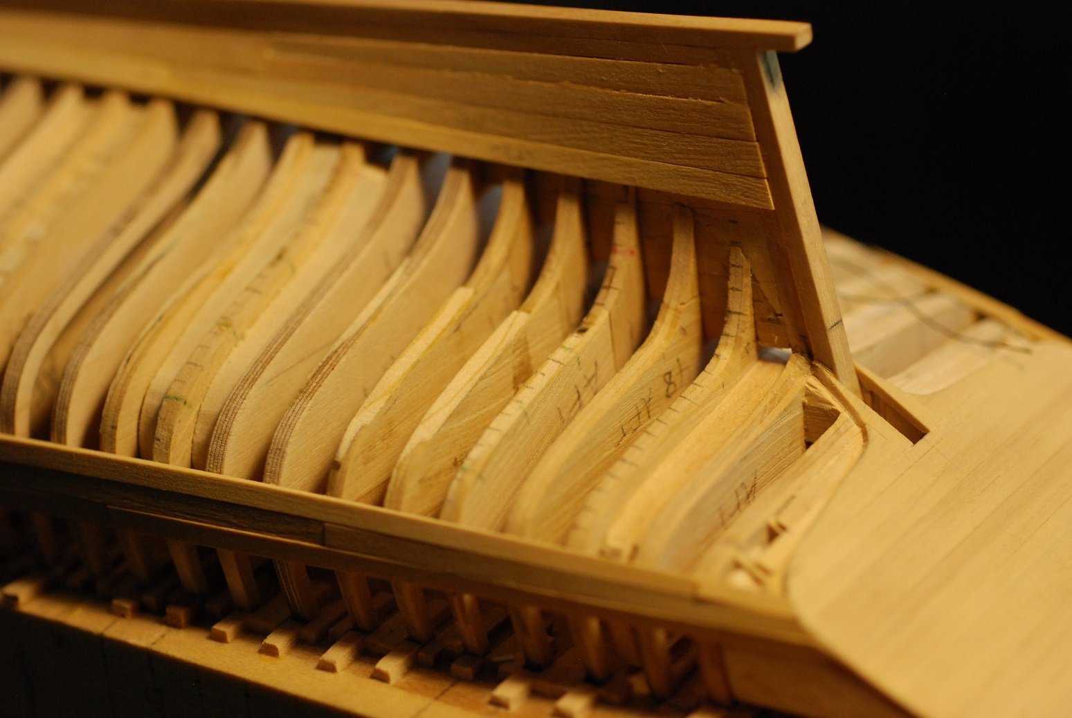
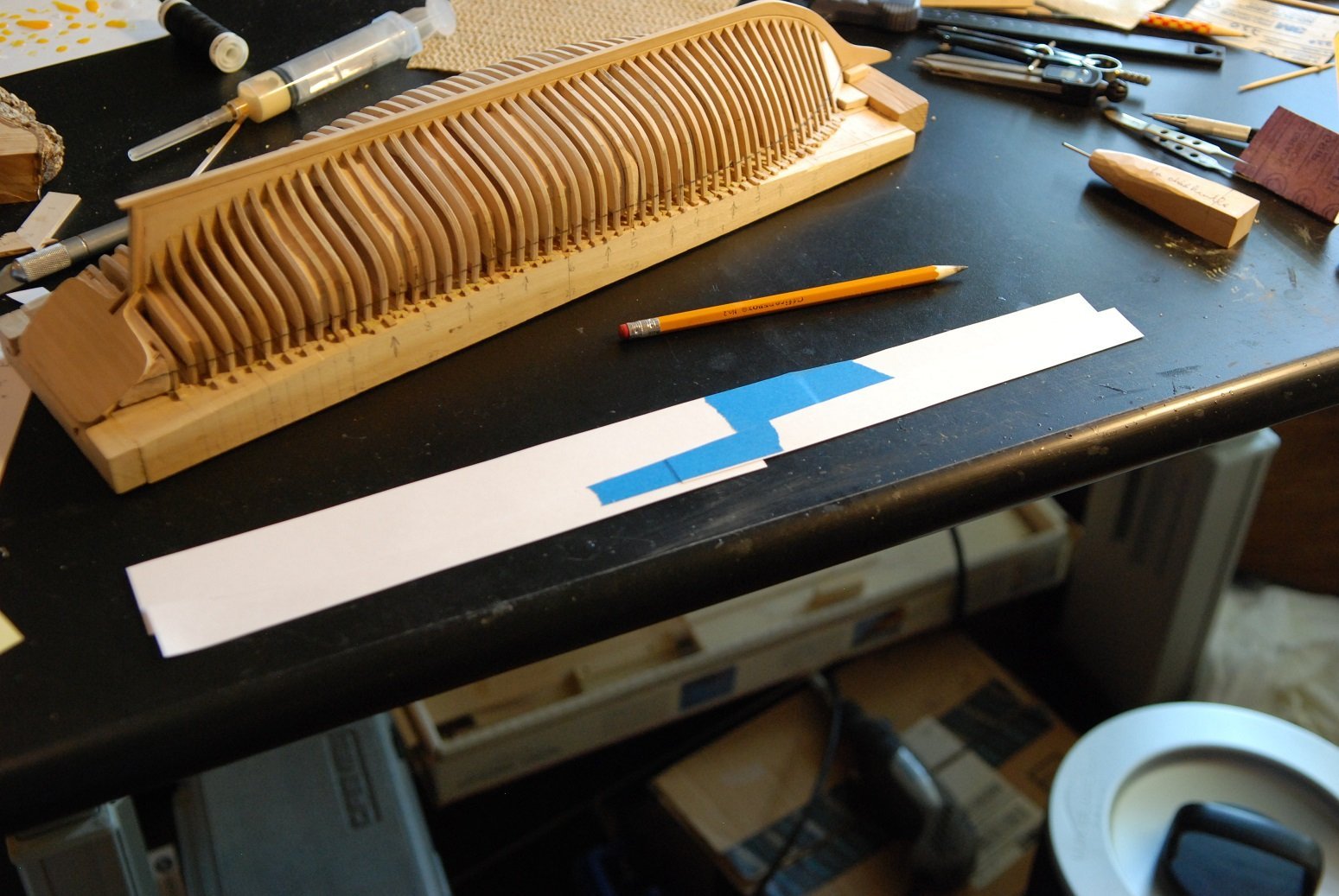
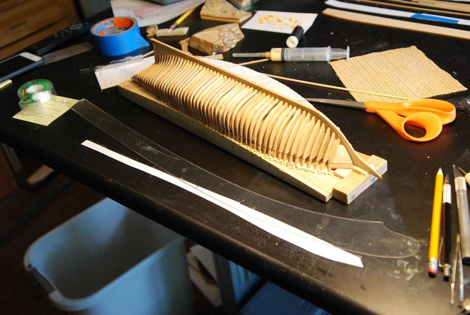
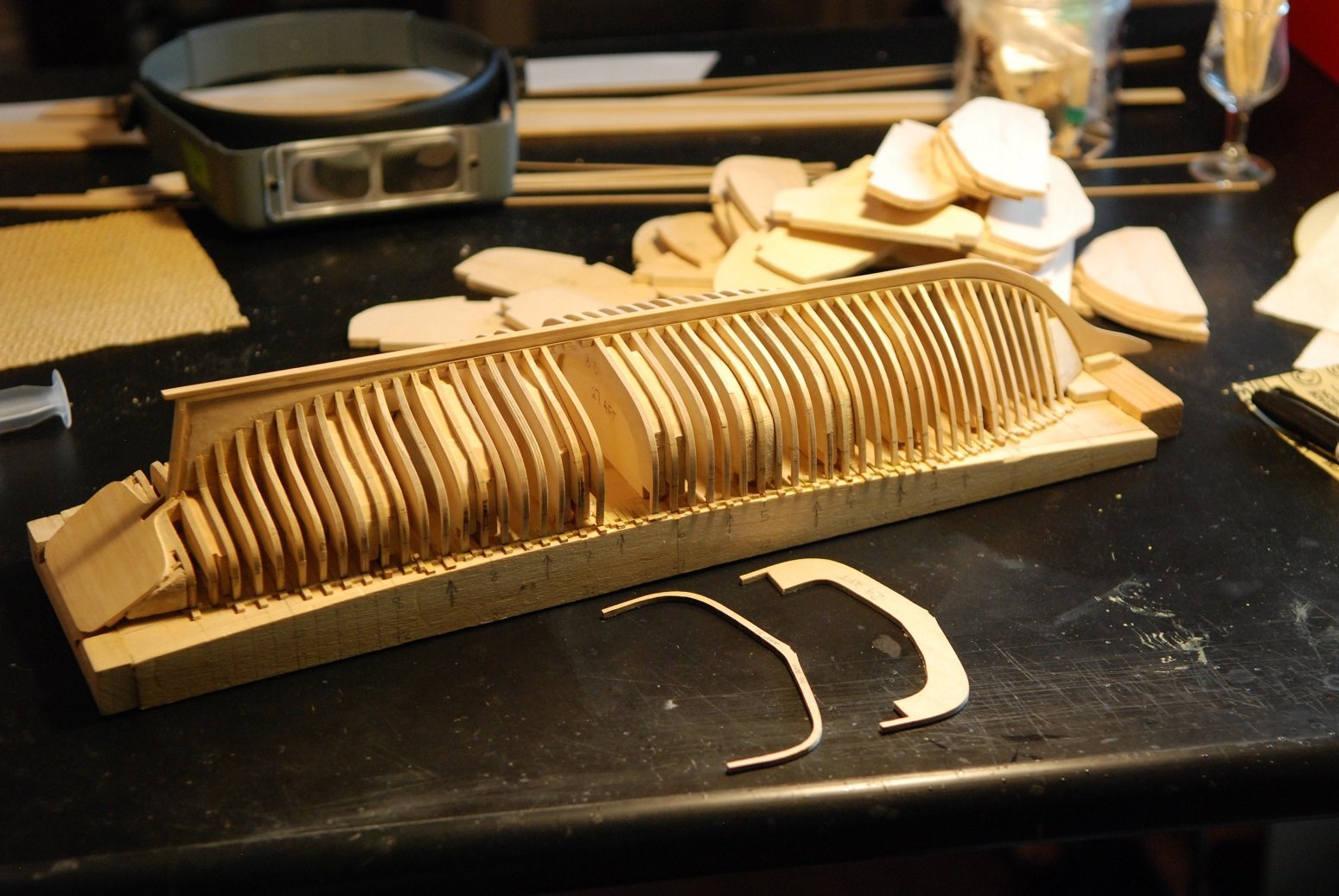
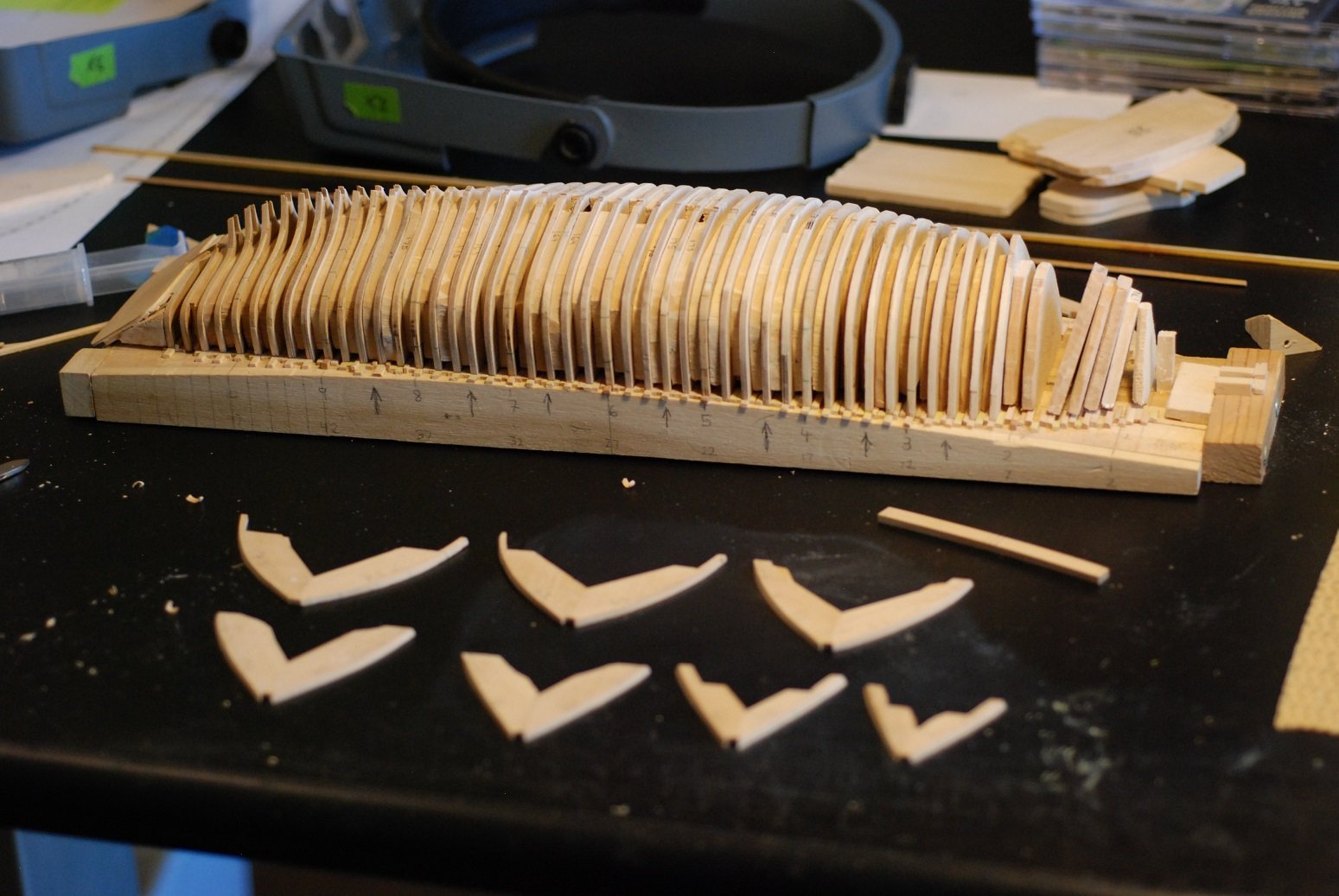
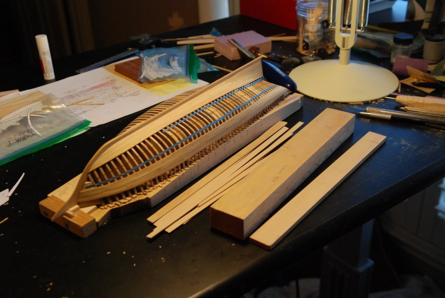
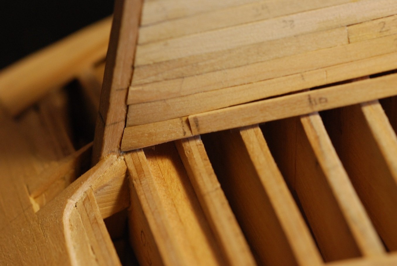
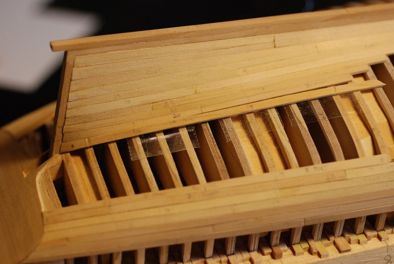
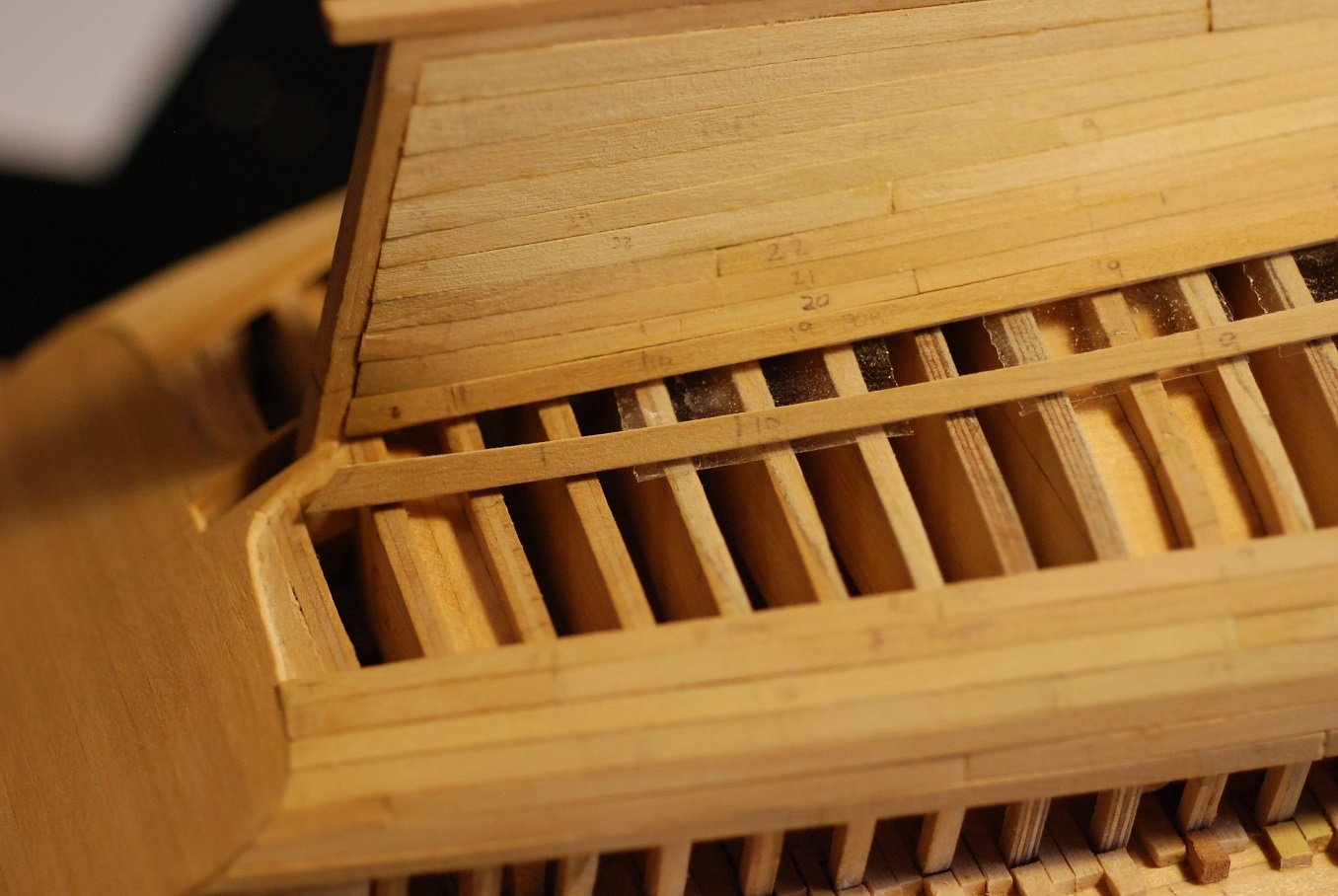
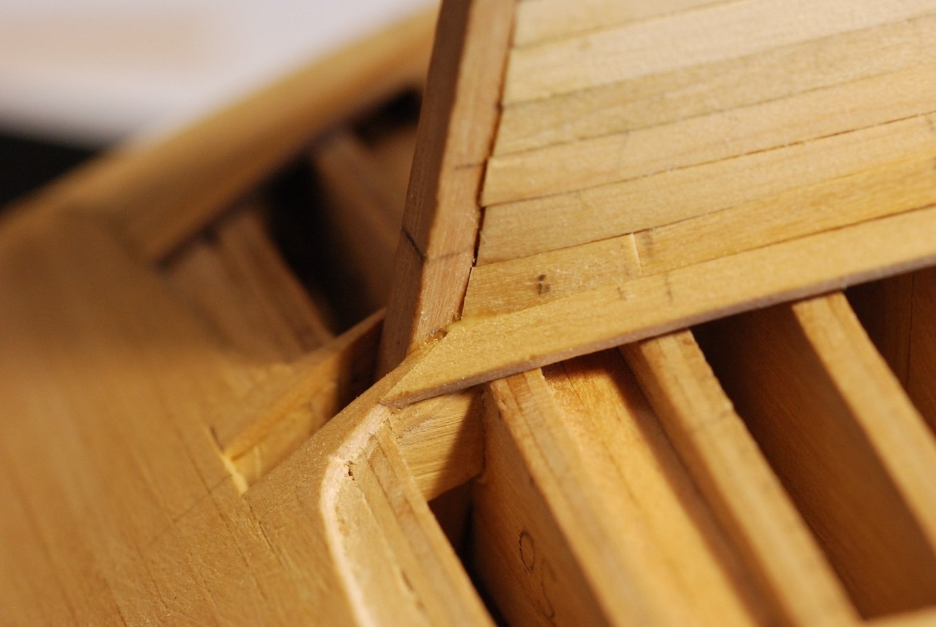
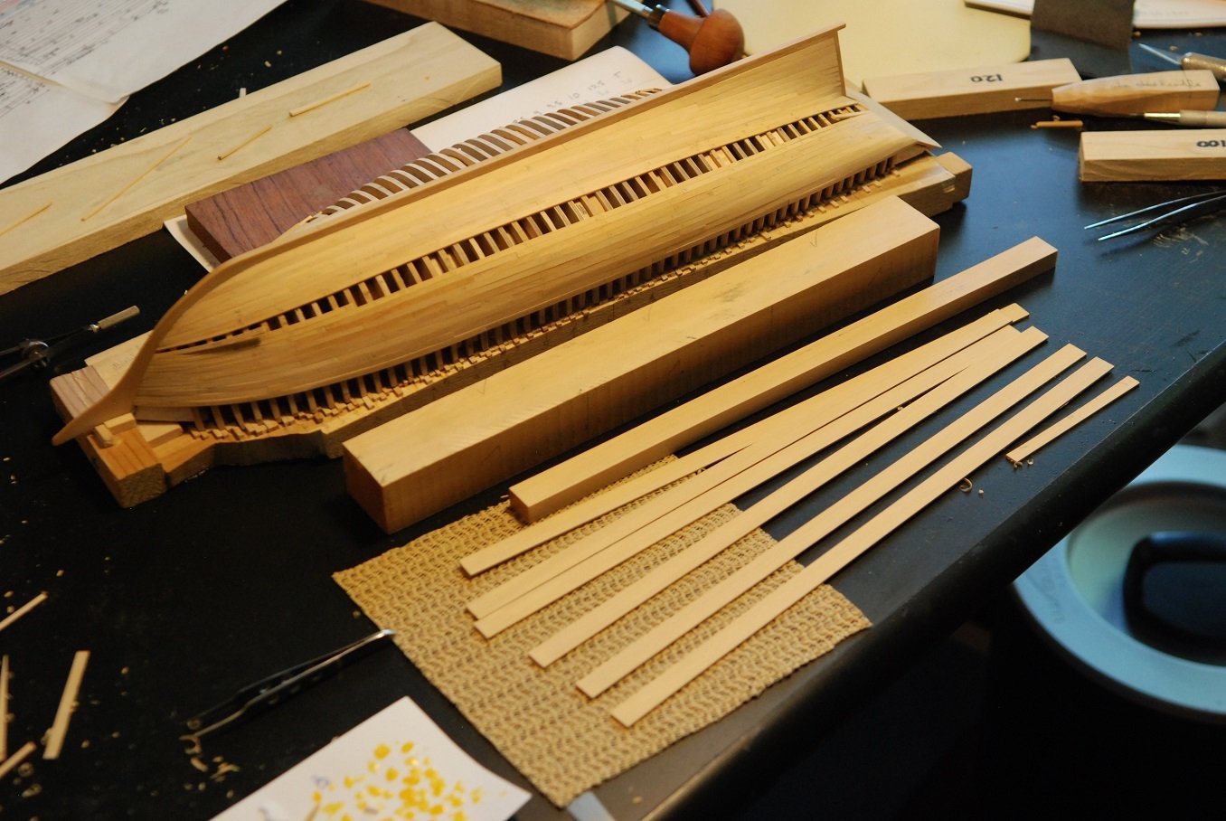
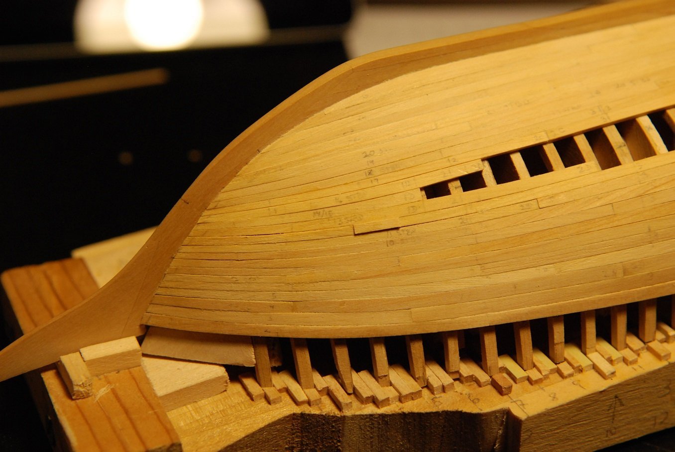
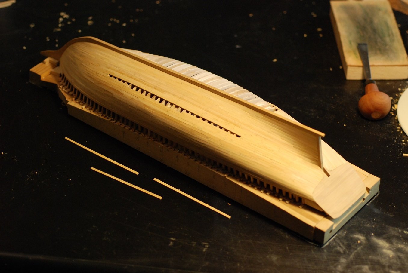
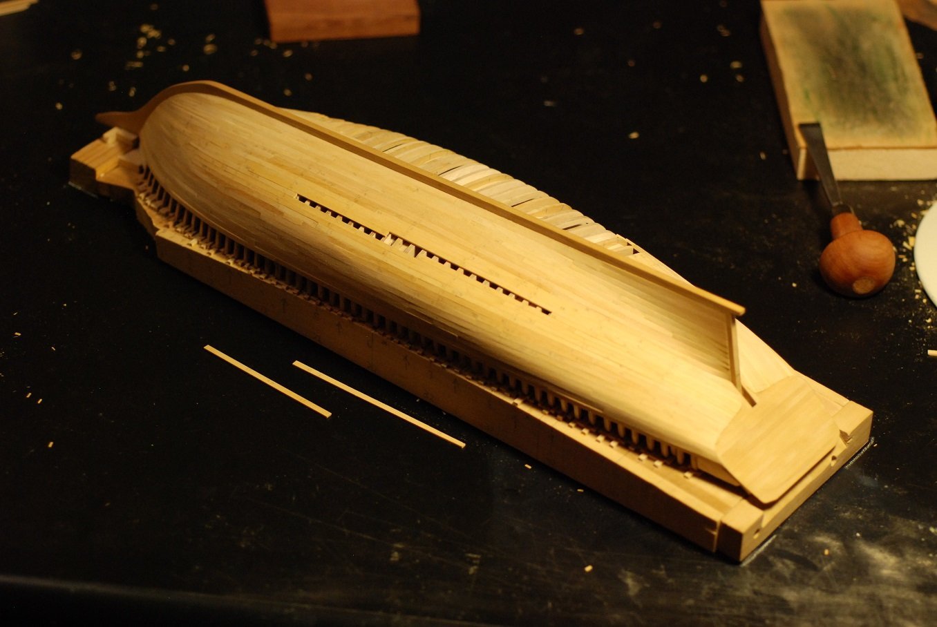
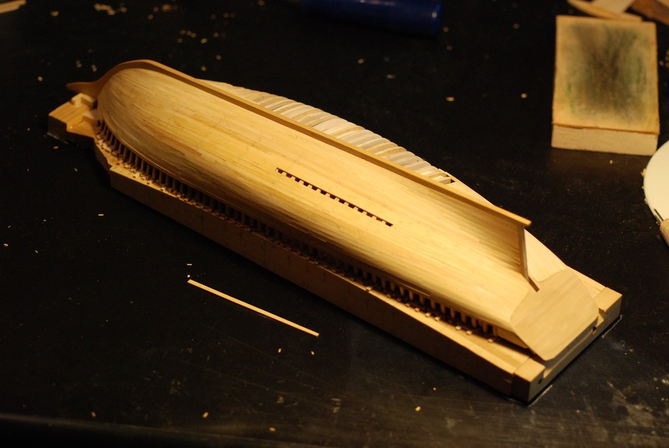
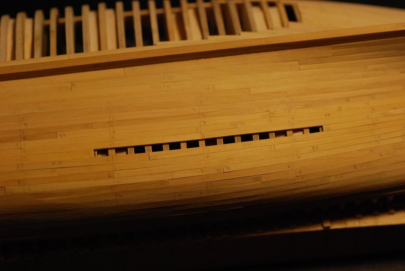
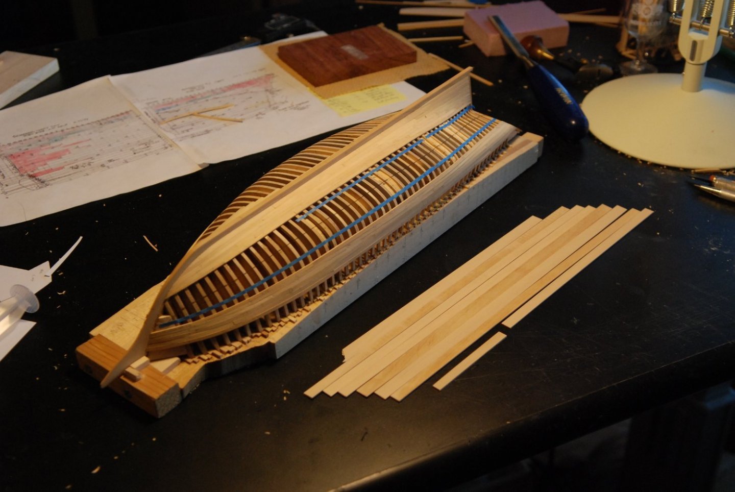
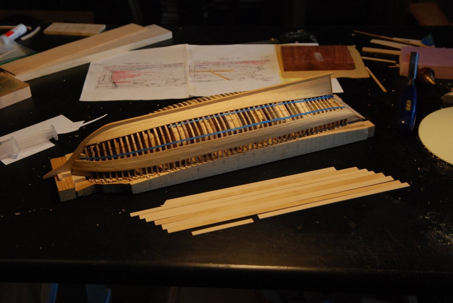
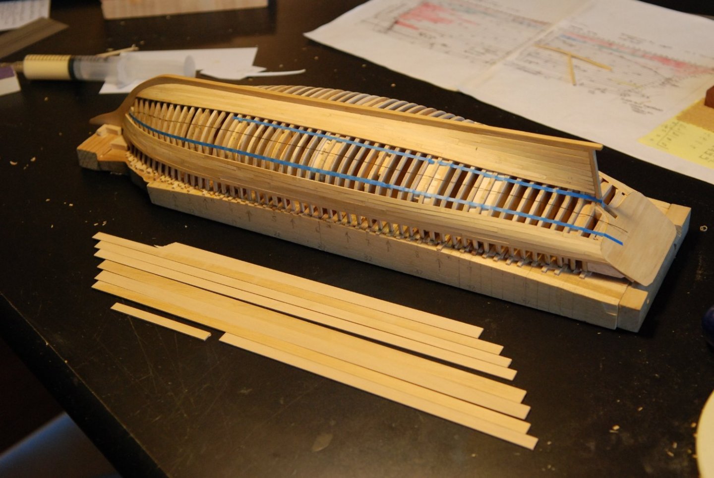
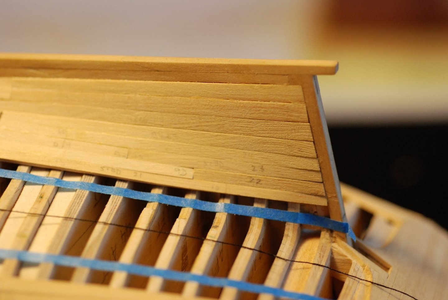
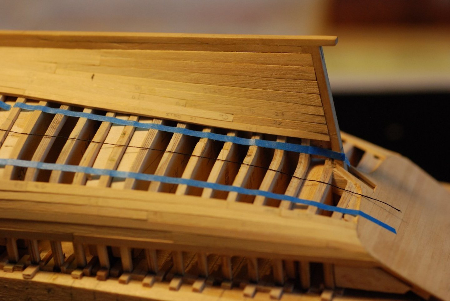
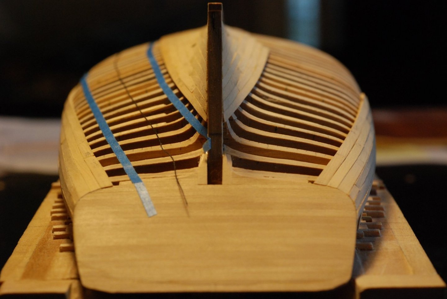
I estimate that I am halfway through planking as of January 5 of 2022. (Happy New Year!) I am hoping to be finished planking the hull by the time of an upcoming trip to Maine, during which I will get to do some more research and measuring. I have piled up my available lumber next to the model as a reference point to see how far this number of strips will take me. As I think I have mentioned, I am leaving a portion of the port side unplanked in order to show the interior structure. The unplanked area will be a relatively oval area centered on the midships. Once planking is finished, I plan on removing most of the wood that constitutes the multiple bulkheads, essentially turning them into dimensionally accurate frames. Not quite sure yet what tool I will use to do that, although I think I have seen a relatively small version of an oscillating cutting tool that probably would work well for scoring the wood so that it comes out easily. Suggestions welcome. In some areas, my tape strips have come off entirely. In other areas, they have shifted position. I am going to finish the lowest and highest belts, and then I will remark things. The string also needs readjustment. Planking band 4 has a low spot that will have to be addressed. Very hard getting the planks to twist adequately in order to accommodate the deadwood planking. And cutting the ends of some of these planks in order to meet the sternpost and the transom planking will be tricky. The higher planks on the deadwood are twisted as they meet the sternpost. That will need to be carved or sanded away to make things flat and smooth.


-
Yes, understood perfectly. Still quite remarkable.
-
Do you have any pictures showing the process of securing the swivel hooks within their swivels? It looks like you had to solder together the hook with its retaining stop, while making sure that the swivel itself did not become fused. How in the world did you do that?
-
Adjustable height desks/tables are hugely helpful in our hobby. It used to be that the only available options were expensive, motorized desks catering to professionals, but manually adjustable tables are now increasingly common. For those that can afford it, visit https://www.afcindustries.com/ if interested in a motorized desk.
-
Oh good, because I have TONS of flexible sanding sticks!
-
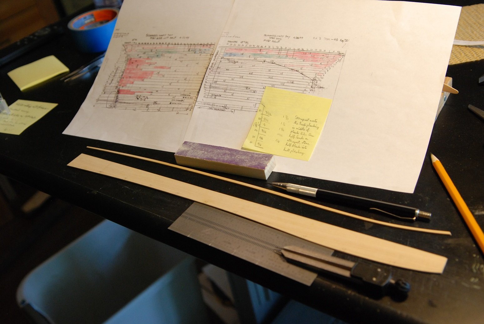
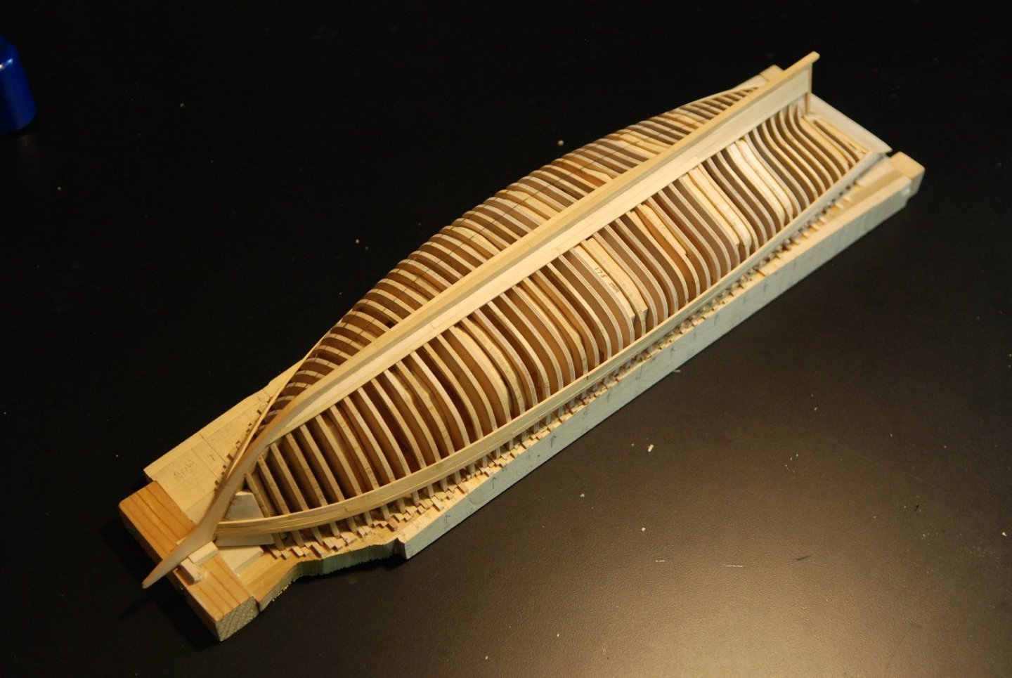
Time to begin planking in earnest. To this point I have added the sheer strake and the garboard planks. The plan from here is to fully plank the sheer and to add one more strake of planking next to the garboard. This will then leave twenty plank widths between them, which can be easily subdivided into four belts. I am using Castello for the planking, from some nice billets I purchased from Gilmer Woods in the Pacific Northwest. I cut this bigger billet into smaller billets from which I can slice off individual pieces and either directly cut a plank, or spile a plank if needed. These are my first attempts at shaping the planks along the deadwood. They have been temporarily fitted with double sided tape. Problem is, in trying to create a nice curve to the edge of these two planks, I have created a hump at the joint between these two drop planks and the next segment of garboard planking. So did I learn the benefits of having spiled one long sheer strake in the previous post. I did not glue these two planks in place, but went back to work creating two new planks with relatively straight contours. The replacement planks have been installed. I don’t have a good “after” picture to show it, but the hump evident previously is no longer present. In this photo, which I showed in my previous post, the garboard planking has been fully applied. The only trick to this was the question of where the garboard plank should end. I had no good guidance on this matter from the planking diagram, so I had to simply use artistic license. A guiding principle was that I did want the garboard to end adjacent to one of the frames, as I am sure it does on the real ship. The forward end was nibbed at frame number 4, and I am satisfied with how that looks. From here, this post is more pictorial essay than anything else, showing the progression of the wale planking. The strings that remain applied to the hull were laid down according to the widths of the planking at each station as determined by my planking diagram, but I was coming to realize that they wouldn’t be that accurate or useful for subsequent planking. Besides, they didn’t look all that fair or pleasant. It was especially tricky to fit the planks at the bow, making sure that the joint at the rabbet was correct while also making sure that the plank was the correct overall length to lie down next to its neighbor further aft. So the solution going forward is to not leave the bow (or stern) plank in a row to last, but put them in place first and lay down the more centrally located planks after that. It is much easier to adjust those planks for length than the ones that meet the rabbet or the sternpost. This was a big moment! After laying down three rows of wale planking as well as the garboard strake, I for the first time pulled the whole assembly off of the building board! It was very solid. I paraded it around the house, showing it to anyone who might be impressed. I think the dogs were the most impressed of all. (Wife: “That’s nice, dear.”) From here it was a matter of adding one more row of garboard planking, so that the remaining planking would be a band of 20 planks. Here I am crafting the hood plank that covers the forward most tip of the garboard planking. Once again I had to learn the lesson of putting this plank in place first before continuing planking toward the stern. This plank, and the others near the bow, did have to be spiled, or they would not sit fairly next to the adjacent plank. Three rows of sheer planking and two rows of garboard planking are fully applied here. I have pulled one of the 3 strings off of the remainder of the hull. This also meant I had to sand off the remnants of glue that attached the thread to the hull. All of the strings have been removed. So now the build log is pretty much current. One last parting picture to show that I am beginning to line off the hull to accept the subsequent planking. I am finding that the widths of planks indicated on the planking diagram have to go out the window, because they don’t appear to correspond to the widths needed on the model. But I will continue to use the planking diagram to lay down the butt joints to match the ship. And I will use the layout for the starboard side on the real ship as the layout for both the port and starboard sides on the model, as the planking layout on the real ship is different for each side. Hopefully things will accelerate from here!


-
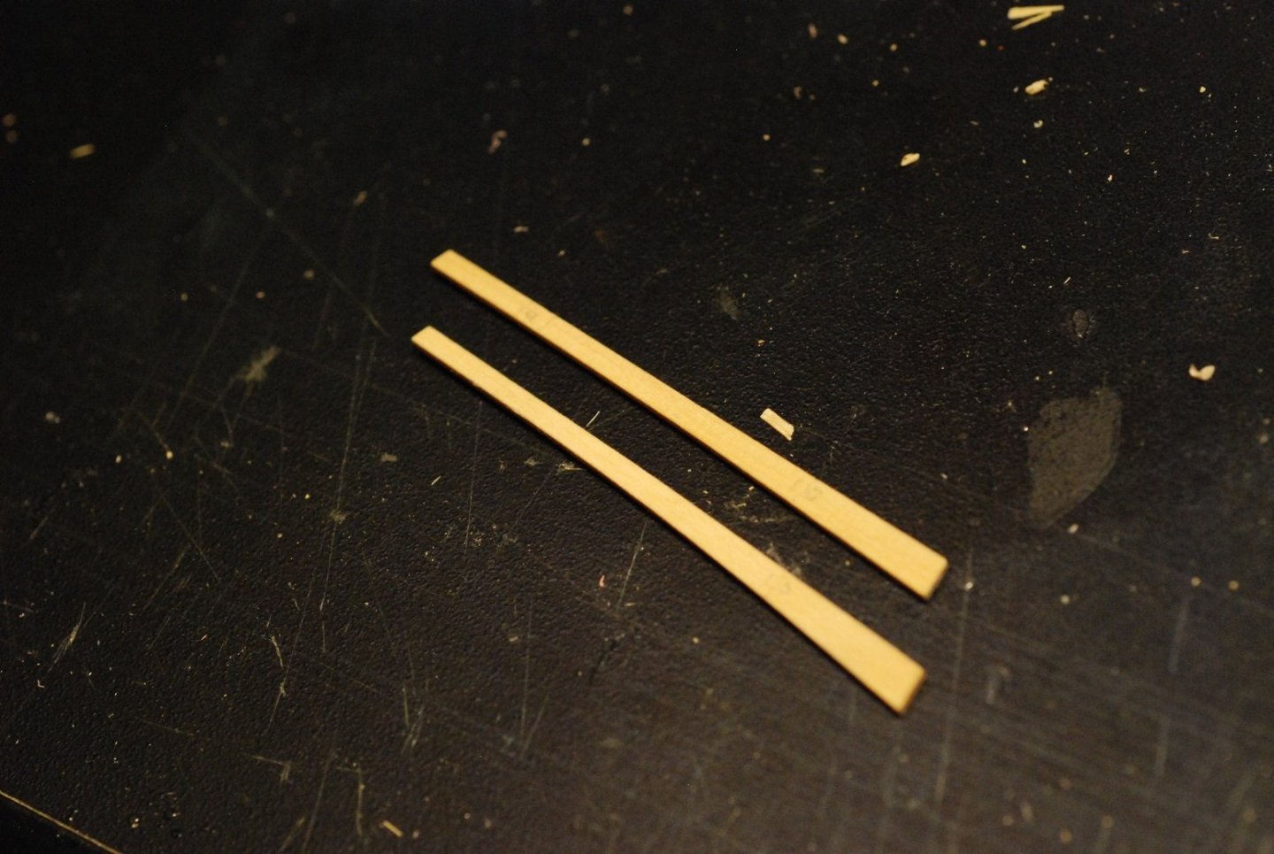
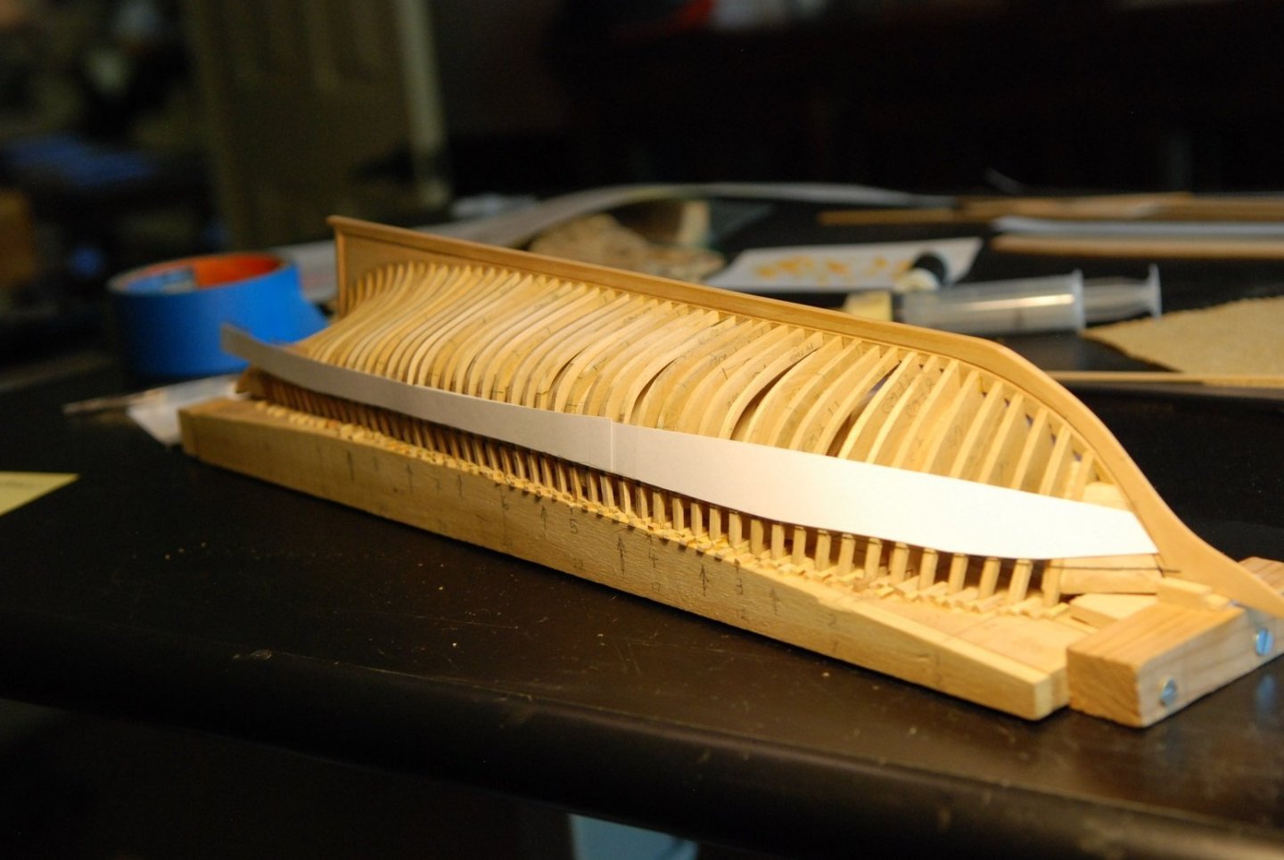
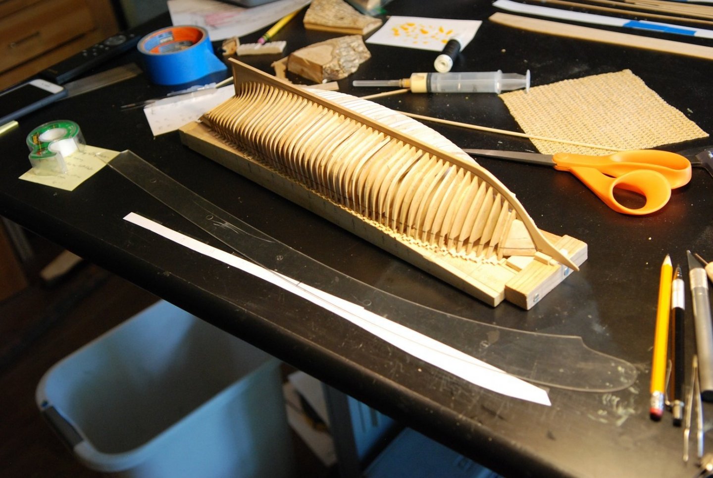
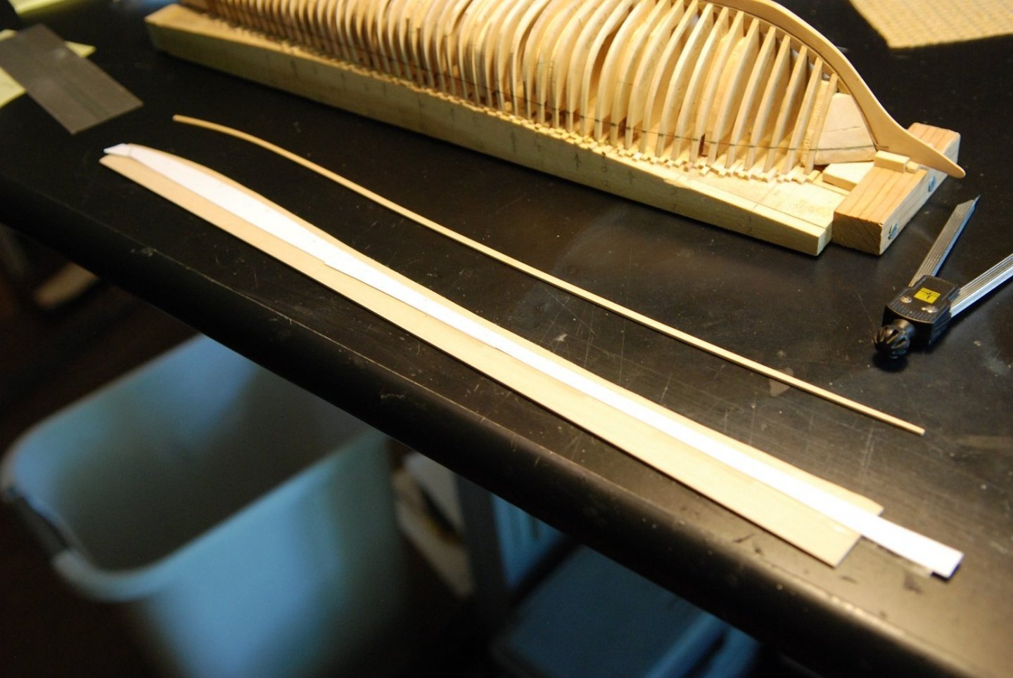
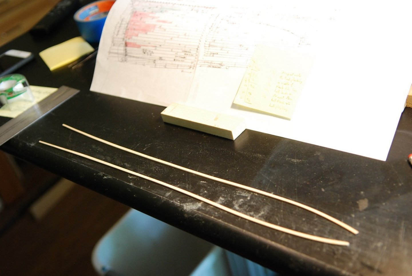
Time to make and attach the sheer strake. There is a thread attached to the frames that indicates the junction between the undersurface of the covering board and the sheer strake. I decided to spile the entire length of the sheer strake, so first I had to put together cardstock long enough to cover the entire length of the sheer. The cardstock was cut to the approximate shape of the sheer and then tacked to the frames with double sided tape. Marks were transferred to the cardstock, and the shape of the curves was defined with ships curves. The cardstock is now applied to a sheet of Castello that is about 0.053” thick. This is thicker than the rest of the planking, which will be 0.047” thick. The picture also shows the starboard side sheer strake, which was previously created using the same process. Widths of the sheer plank were obtained from the planking diagram and transferred to the Castello sheet. Then the plank was carefully cut out and sanded to the needed widths. Port and starboard sheer strakes. I could have divided the long segment into individual segments as indicated by the planking diagram, but I thought it was a good idea to do the first plank as one continuous plank, to serve as a baseline against which all the other planks would lie. I think that worked out nicely. There were some problems along the way in getting to a smooth lie of the sheer strake, but all is well that ends well. The one long strake was divided into its respective parts as indicated by the planking diagram; the challenge there was to make sure that no kinks occurred at the butt joints between plank segments. Now that is a very satisfying curve.


-
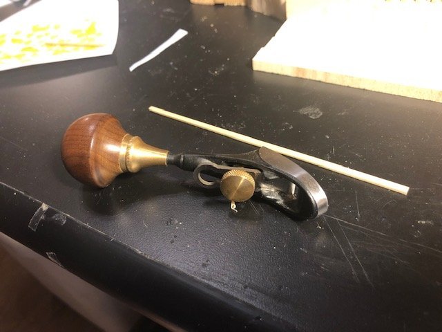
A quickie post to show that I finally found a proper use for this palm plane I bought awhile back from Lee Valley (love their stuff). This hand plane has made it very easy to plane the edges of planks down to their needed widths. So far I am doing this while holding the plank in my hand, but I think I will build a jig to hold the plank on its edge so that it will be more secure and so I can get to the full length of the plank in one swipe. Check out the palm plane! It has been sitting in a drawer waiting for its shining moment.
-
Thanks for the likes! I plan on putting on three strakes of sheer planking, plus the garboard planks, before I even consider testing the stability.
-
Hi Michel, is there another forum where you have continued your build log? Perhaps a site based in France? I am interested in seeing any progress you have made. Merci!
-
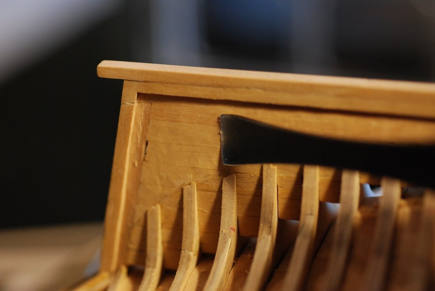
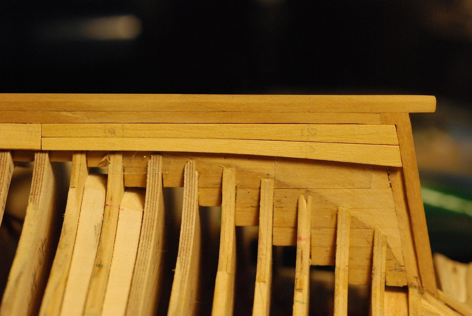
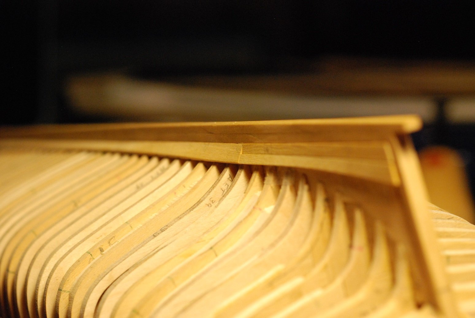
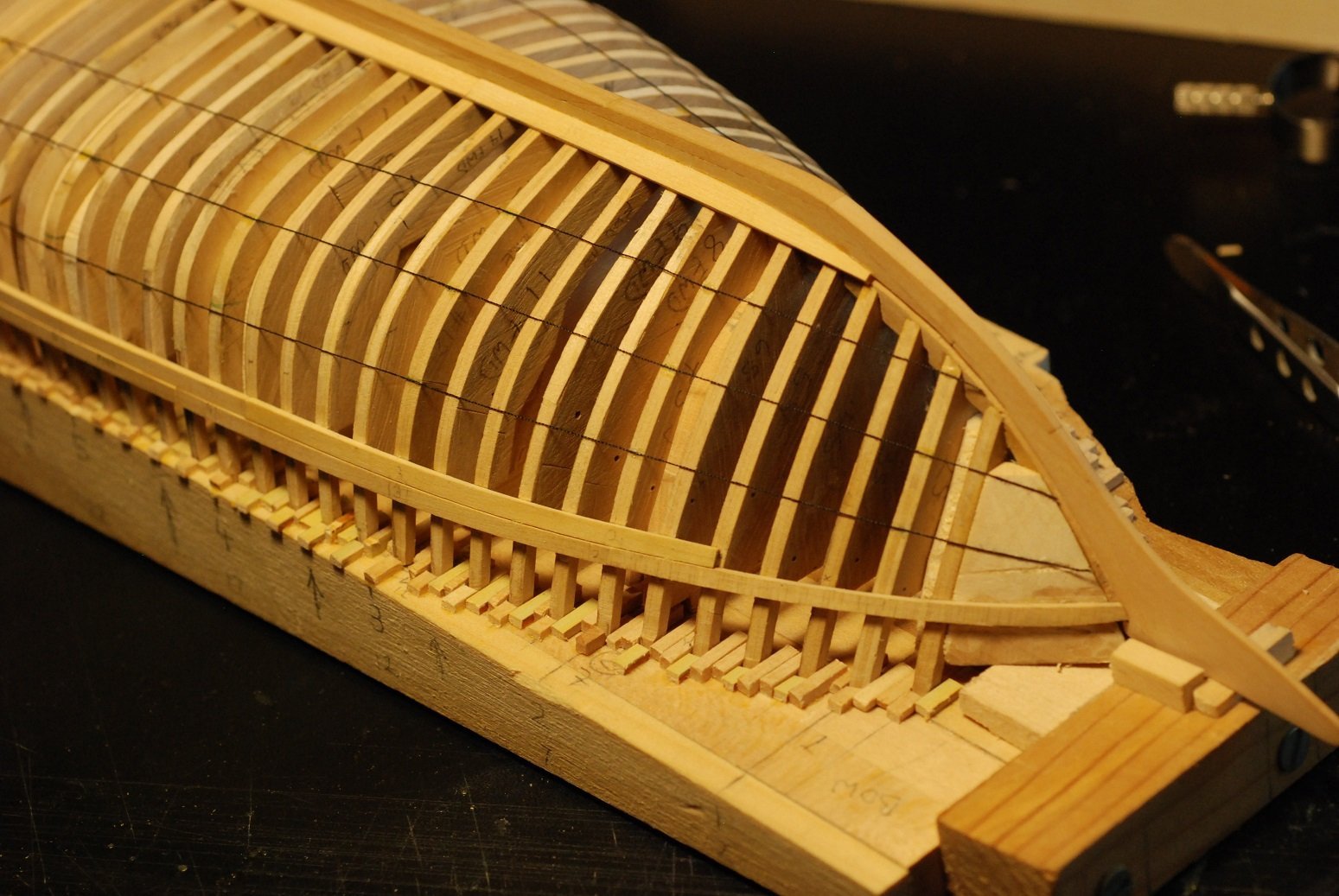
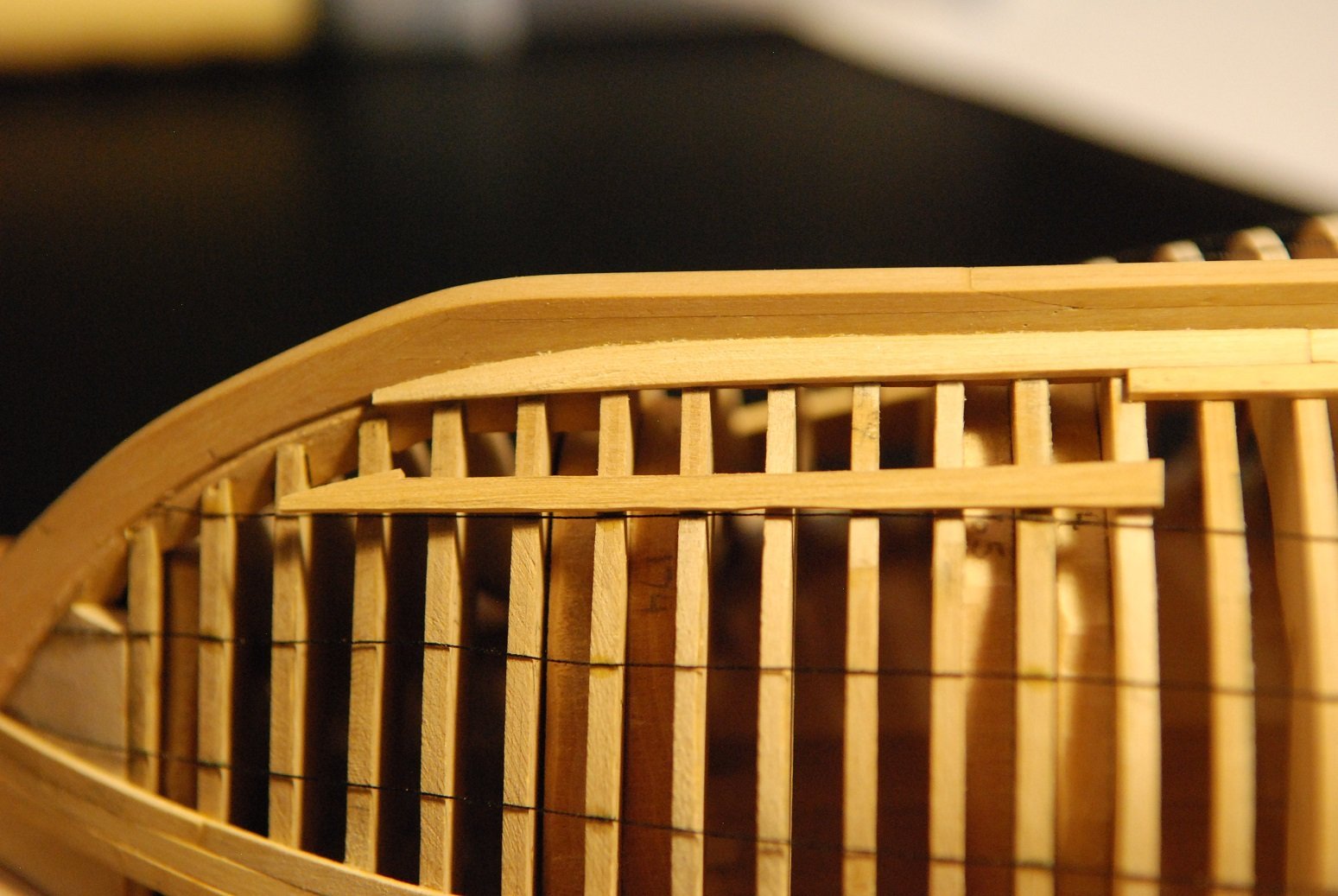
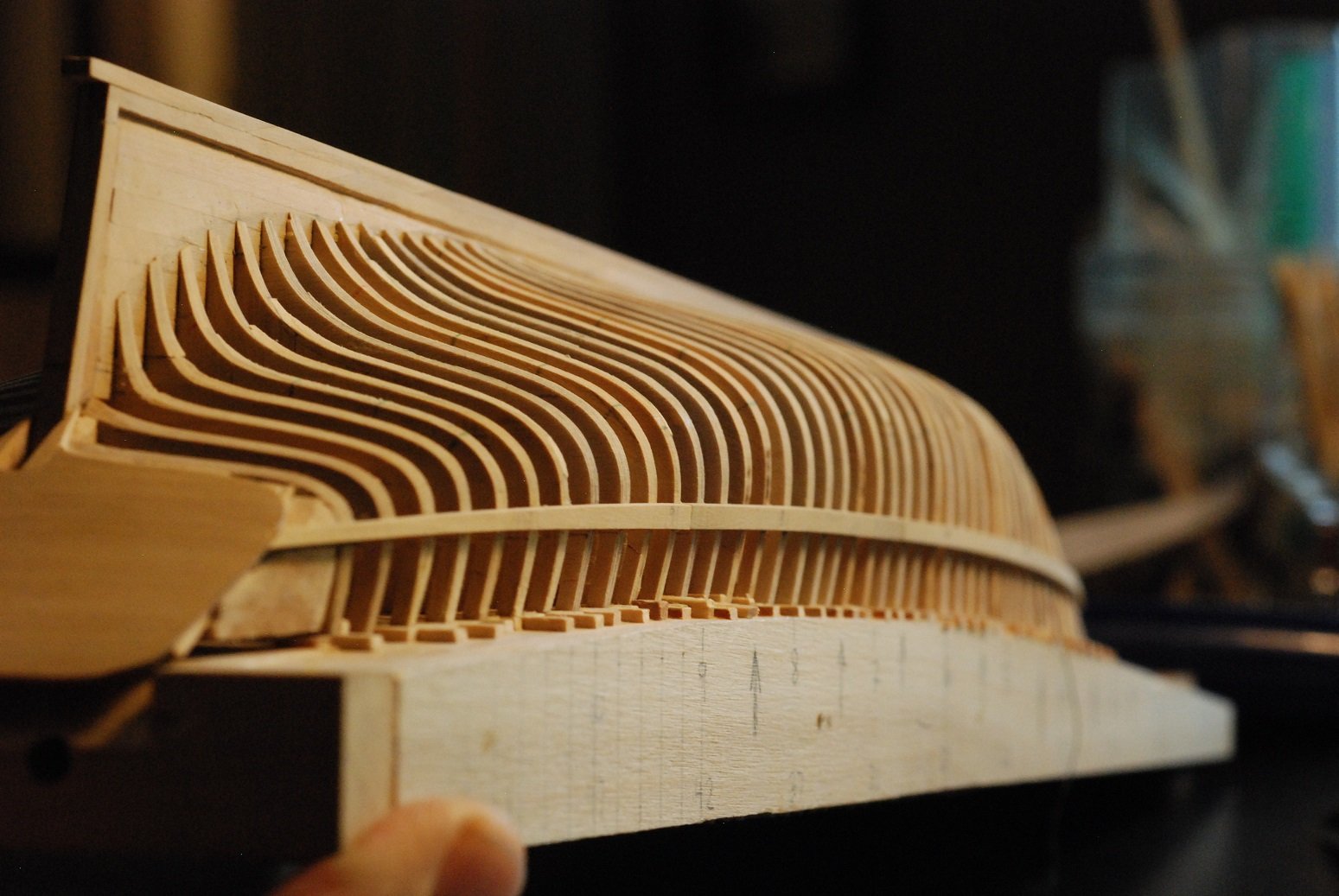
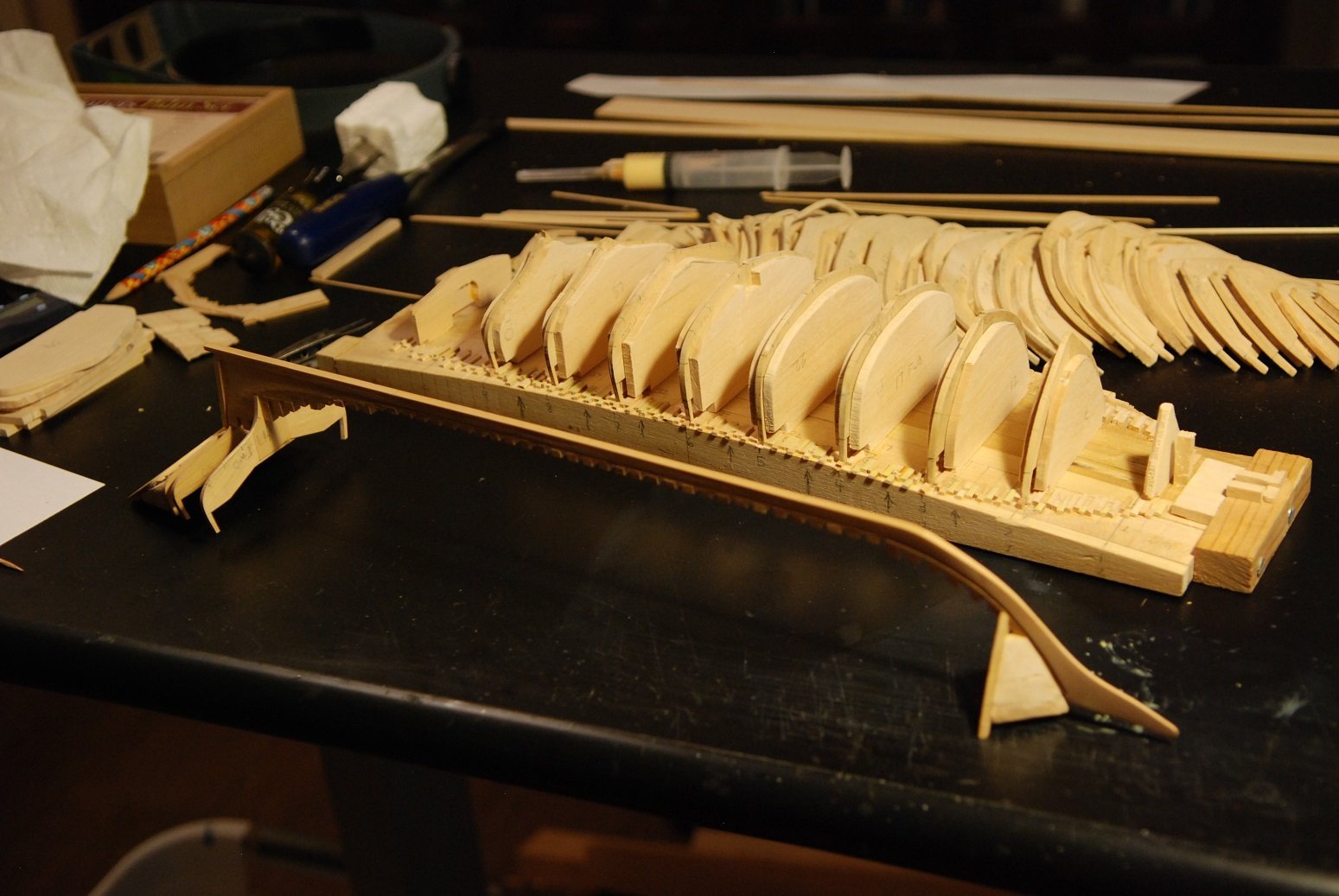
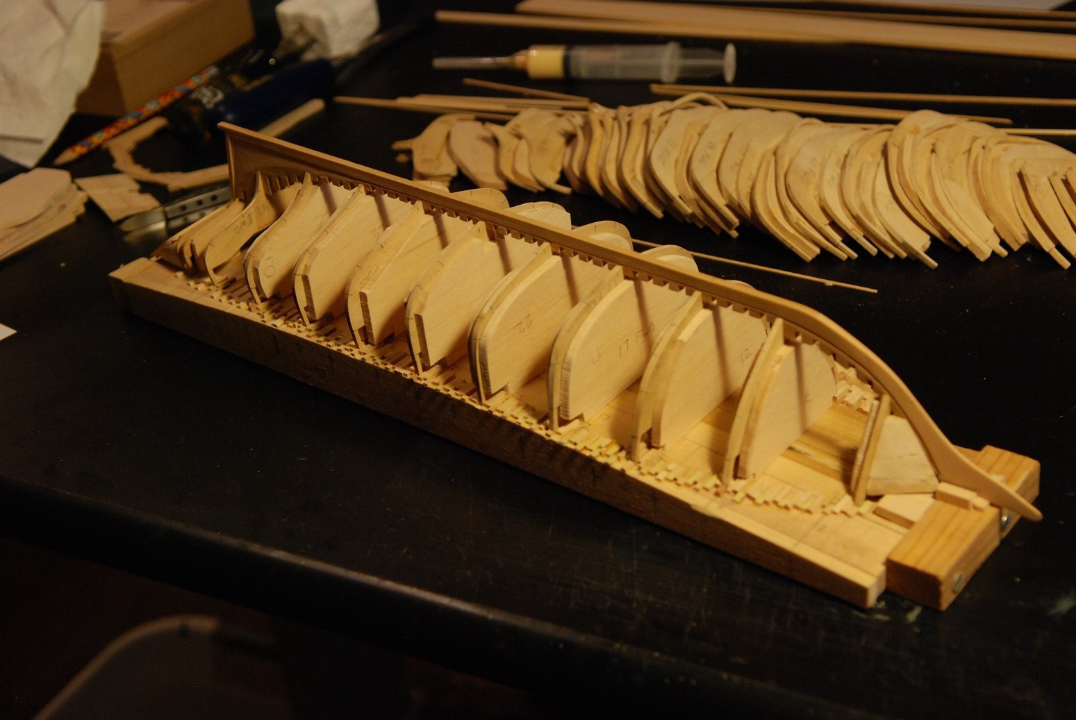
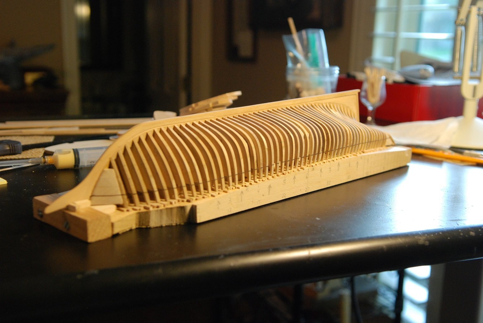
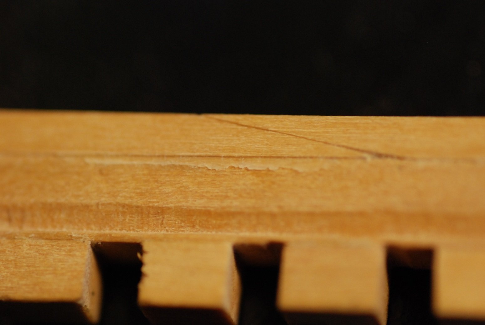
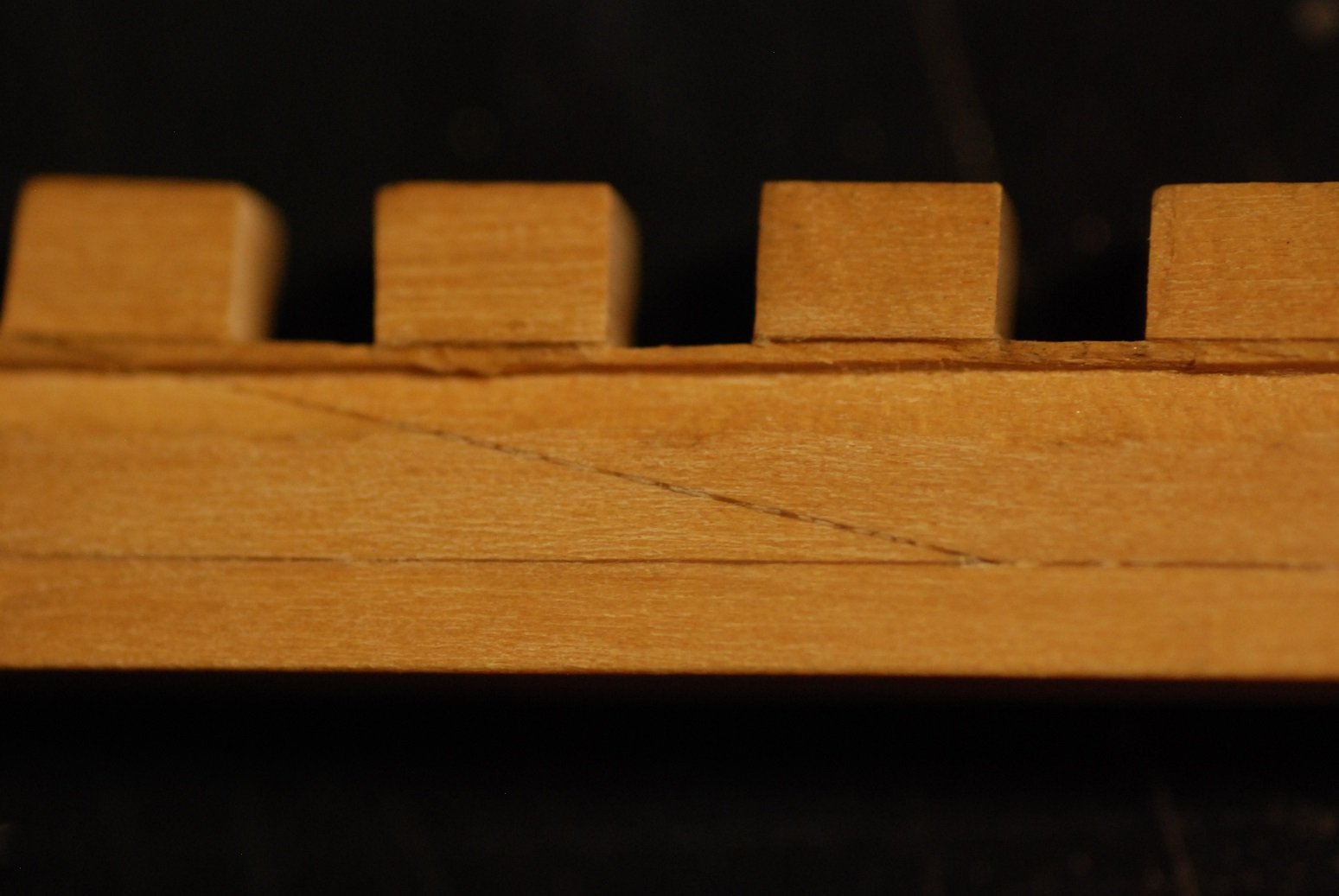
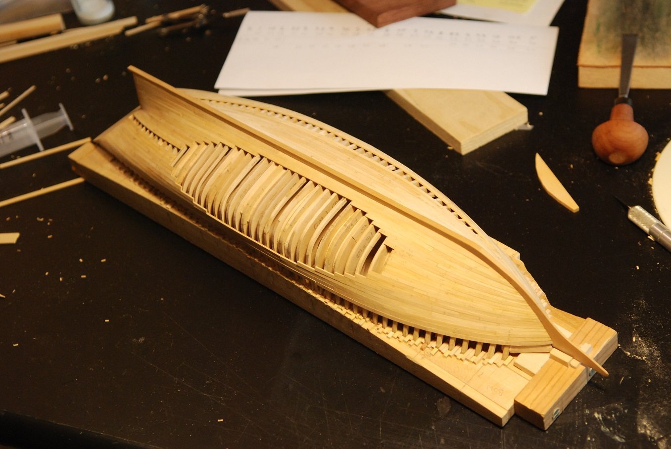
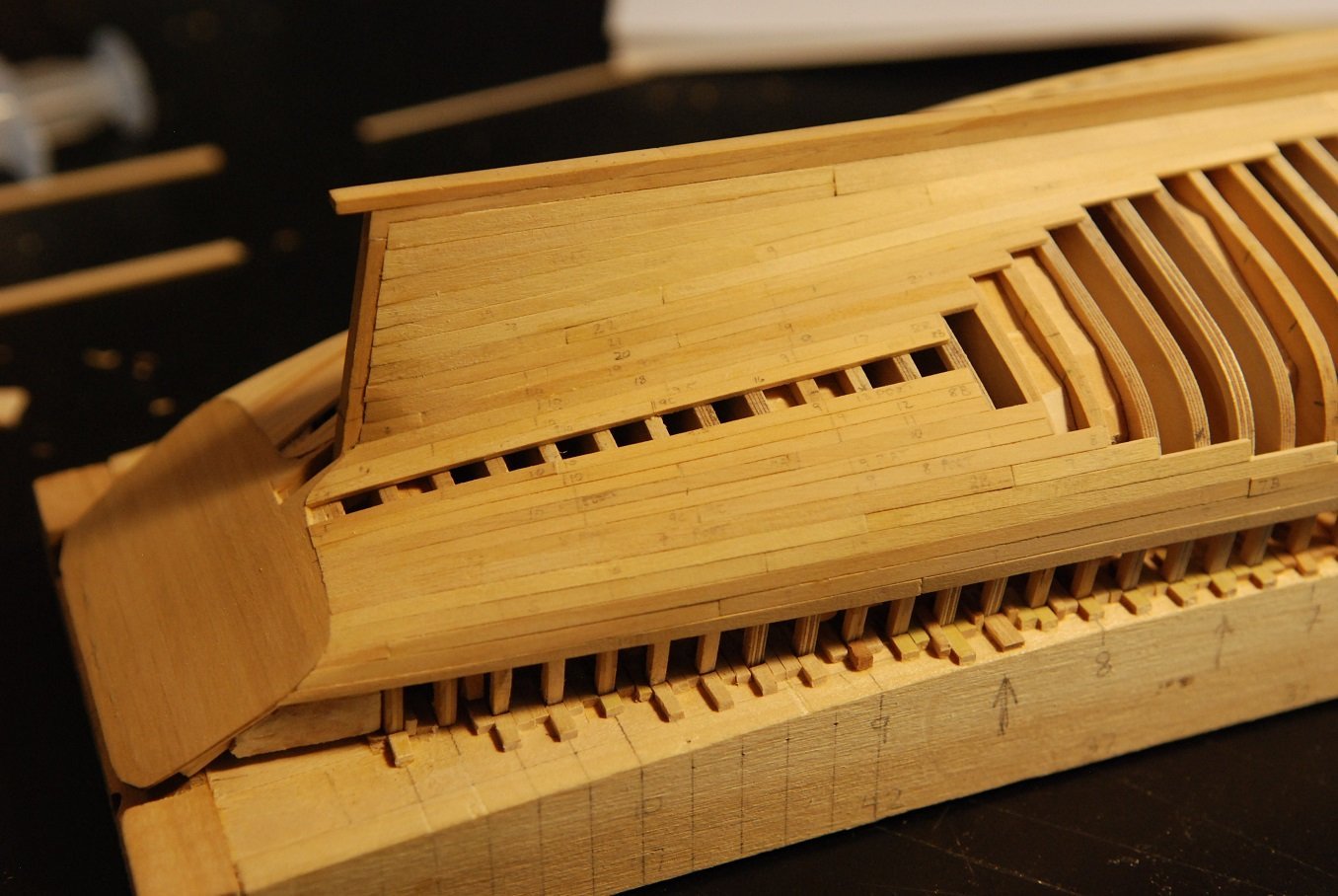
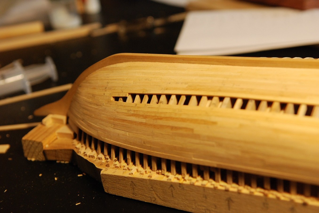
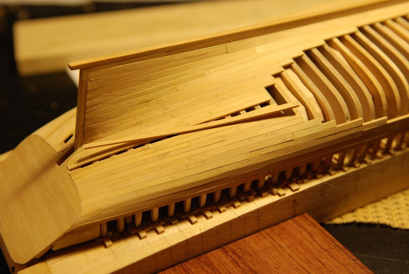
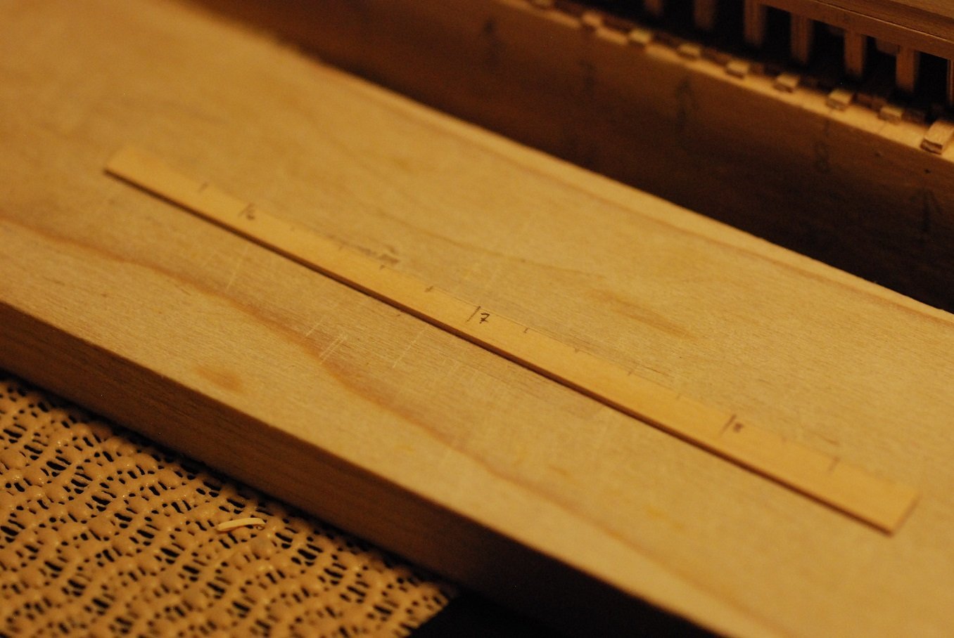
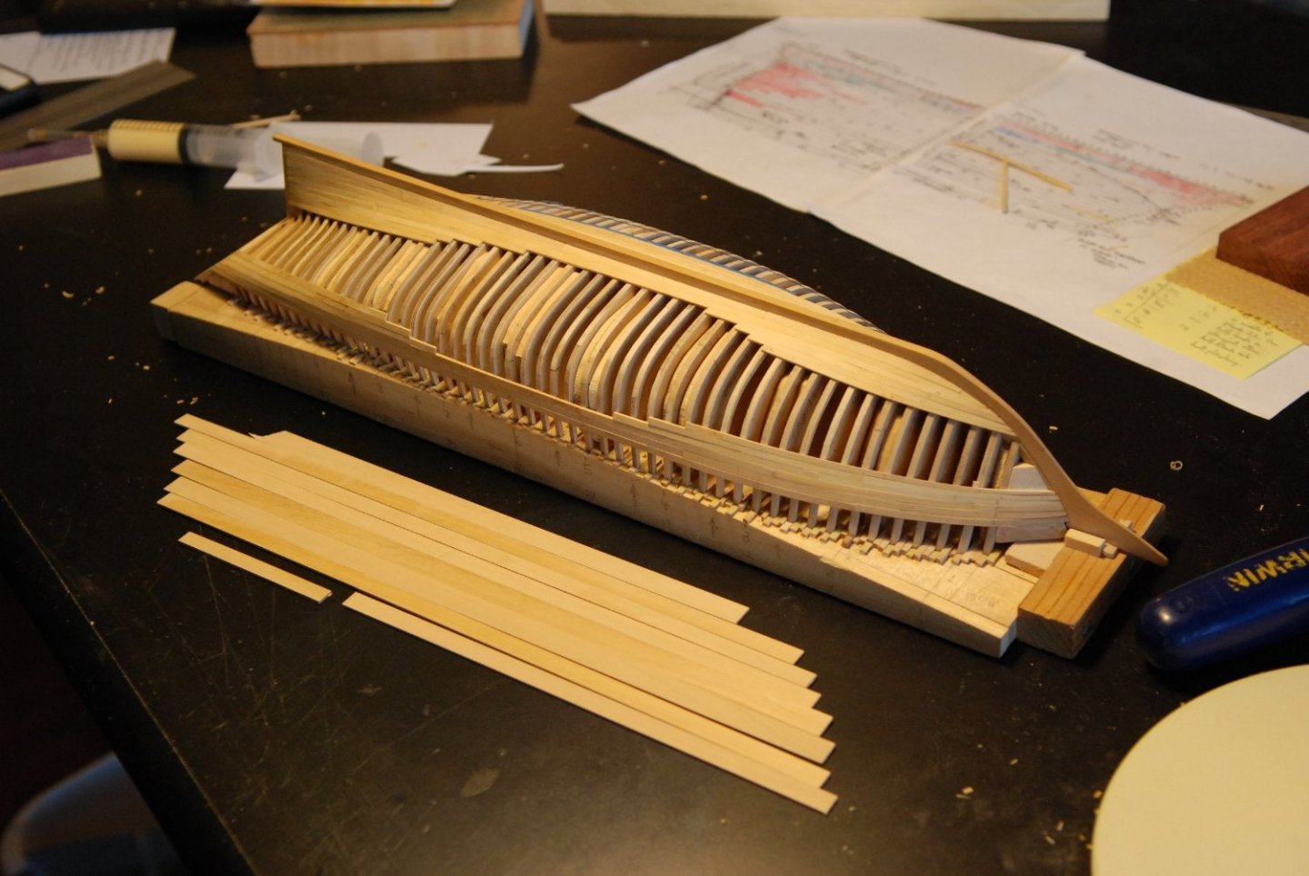
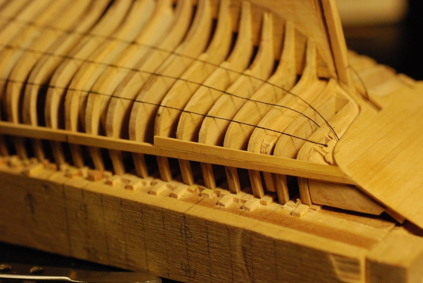
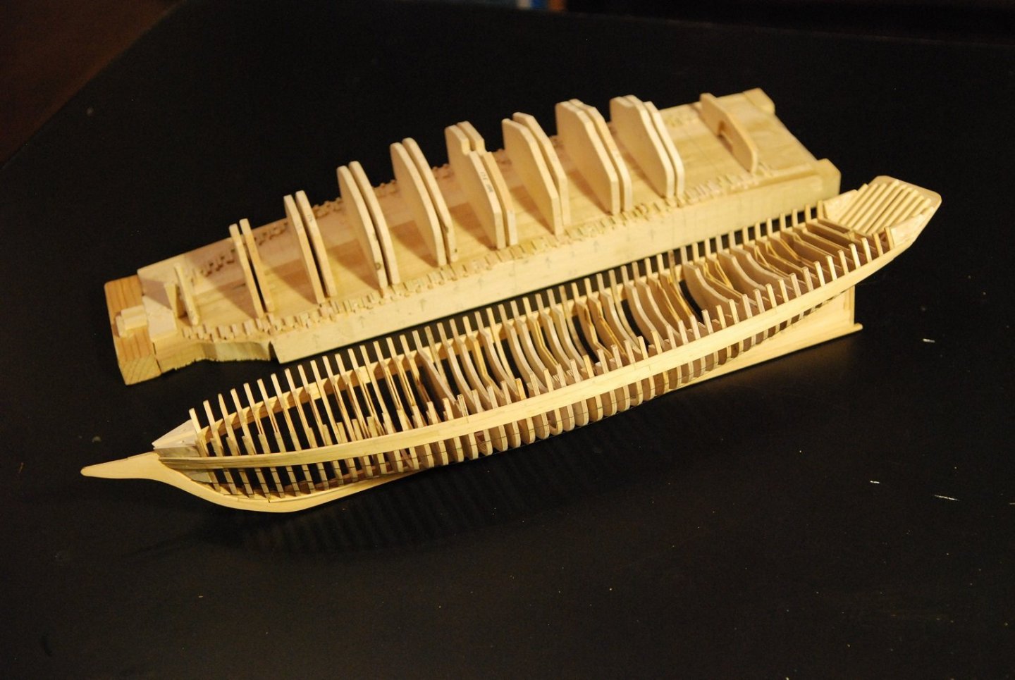
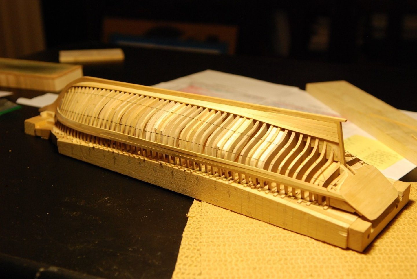
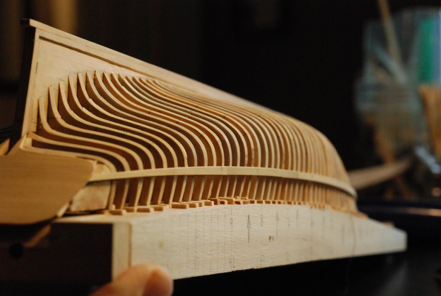
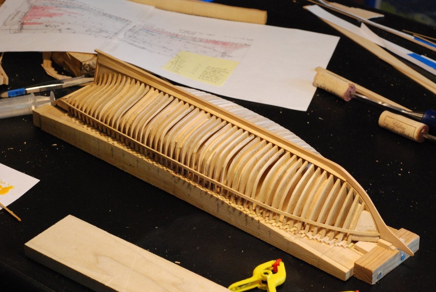
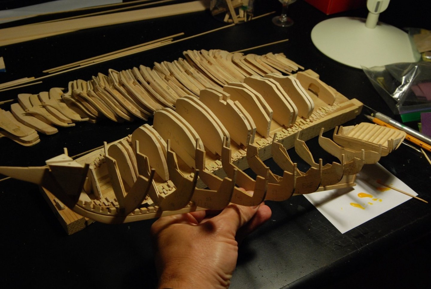
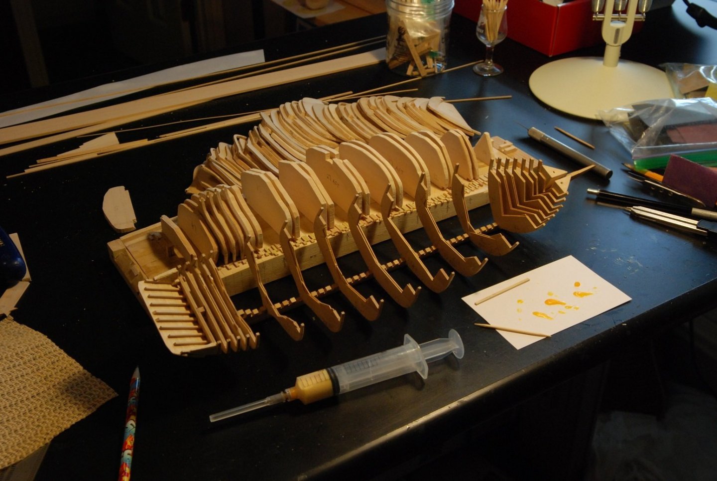
For some time now, I have been stalled out. This is probably because I am at the point of beginning the attachment of the frames to the keel. I could probably keep fairing the frames, a process that I hate, in order to put off the next step. But I feel like I need to accept the hull shape as it is, and get on with next things. First of those things is to go ahead and attach the bow filler blocks and frame 1 to the keel, as well as attach the transom assembly to the sternpost. I also attached the penultimate frame, which is #50. This is shown above. On the building board, the frames at each station are waiting in their slots for the keel to be attached to them. It was terribly important to get this step right and to ensure that the keel is completely inserted into the notch on each frame. So I glued two frames in place at a time, elevating the keel just enough to get the glue into the space between them before lowering the keel down onto the frames. After applying glue and getting everything in place, I weighted the keel with a piece of wood. FYI, that is a piece of “African boxwood” from rarewoodusa.com in Maine. The species is given as “Buxus macowanii”. I have not used any of the wood I bought from them in the model yet; thus far I have been testing it out for its carving qualities. All of the station frames have been attached, yielding this delicate structure when it is removed from the building board. And so begins the process of adding in all the frames between the stations. This was even slower, because of the need to once again make sure that each frame articulated correctly with the keel. Failure to do so would cause focal unfairness at that frame that would be most noticeable along the bottom of the boat and at the rabbet. The last two frames are about to be glued in place. Most of the frames are in the form of the one on the right on the table top. However, about every fifth frame has been trimmed to its proper molded dimension, and that information comes directly from measuring the dimensions of the frames on the real ship. All frames are now glued in place. I ended up finding one frame, about #11, which was not fully lodged into its slot on the keel. It is not evident on this photograph, as the difference is probably only 1/32”. It is visible if one gets up close to it. But I decided not to do anything about it. The whole reason for this exercise? I may have covered this before, but will go over it again. I wish to be able to leave part of the hull unplanked and show the interior structure of the hull. But building this model in the same way as one might build a fully framed fifth rate of the Royal Navy would be very difficult, as the frames would become very fine and fragile. It just wouldn’t be possible to accurately plank a structure consisting of a backbone keel and rib-like frames that are very pliable. So the plan is to plank up nearly all of the hull, leaving part of one side unplanked. I don’t yet know if I will fully plank the hull and then remove some of the planking, or if I will simply leave an area unplanked as I go along. I am favoring the idea of fully planking the hull, but only lightly gluing the planks that will later be removed. This is because I am planning on trimming out the majority of the material that forms the frames once the planking is finished, bringing the frame dimensions down to their proper molded dimensions. Thus the importance of having every fifth frame trimmed down to its proper molded dimension, so as to serve as a guide to that process. I will probably only do this for a certain portion of the hull, leaving the frames untrimmed in the bow and stern. In order to have the hull as stable as possible before doing the interior trimming, I think it would be best to have the hull fully planked. Feel free to offer opinions in support or in critique of this plan! So, all frames are in place. This really was a big psychological step, because from here one has no place to go besides getting on with the planking. And I certainly like planking far better than fairing the hull. Honestly, I could have spent more time fairing, and there are areas where there will be gaps between the frames and the planking. But it was time to move on, and gaps can be dealt with later. This process illustrated in the two pictures above was very satisfying. As has previously been suggested by a commentator on this log, I used black thread to lay out the top of the sheer plank, where it meets the covering board. The plans indicate that this point is to be found on each frame, very consistently 7/16” below the top of each frame (also the bottom surface of the rail). So this point was marked out on each frame on port and starboard sides. The thread was then glued with white glue to these points, which yielded a surprisingly crooked line that was probably due to marking error. After all, the line should parallel the surface of the baseboard, which is cut to follow the curve of the rail at its undersurface. This picture of the aft portion of the hull gives some sense of the crookedness of the line, if just left to my marks. How satisfying indeed, then, to be able to look at the curve of the baseboard, and then simply moisten the glue spots on the thread and adjust the thread up or down as needed in order to obtain a fair curve! It’s one of those moments where I feel like an actual shipbuilder. I don’t have good photos to show the process in action, because to do so requires photos with very great depth of field, and those involve long exposure times. In the end, though, I am left with a very smooth and well defined line to follow when I attach the sheer strake. I am going to stop at this point lest I make the post too long and cumbersome to transfer to the web page. Hopefully the next post showing the application of the sheer strake will follow promptly!


-
Your splicing tools appear to be hypodermic needles with the edges dulled so that they don't cut the line. Is that right? Genius!
-
Thanks Druxey, hope you are well!
-
Ganz herrlich!
-
When you use the term varangues, does that refer to the lowest part of the frame, i.e. the floor timber?
-
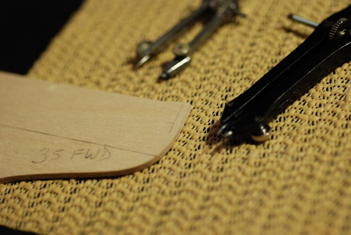
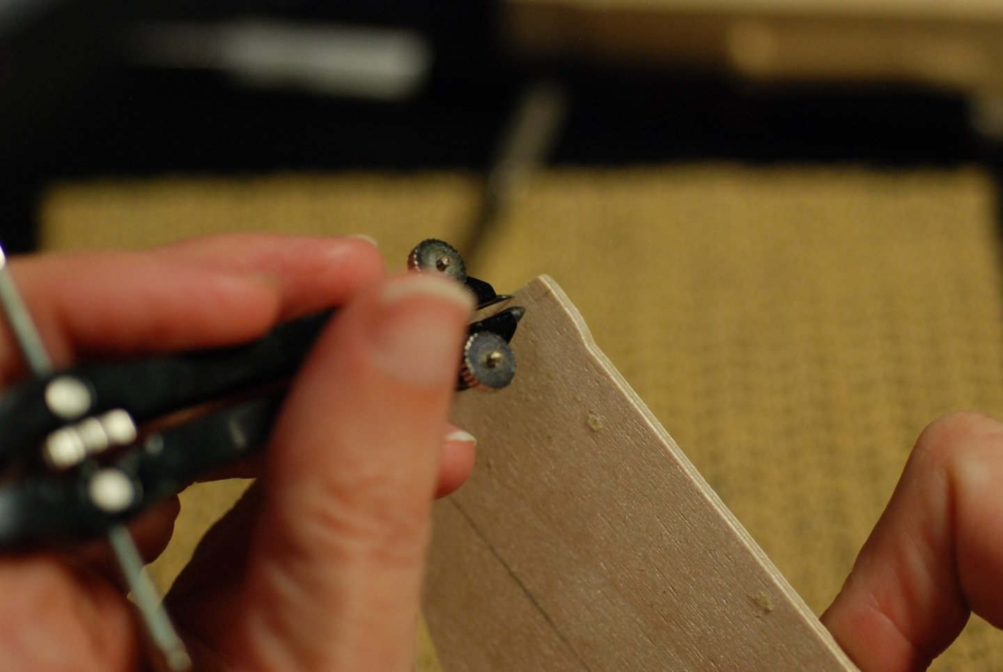
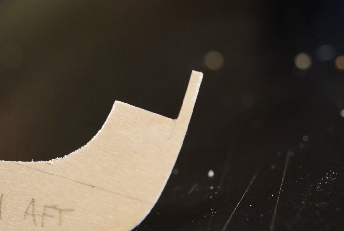
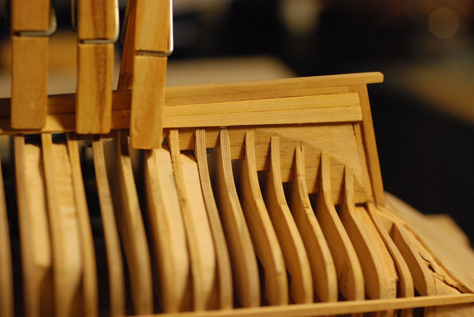
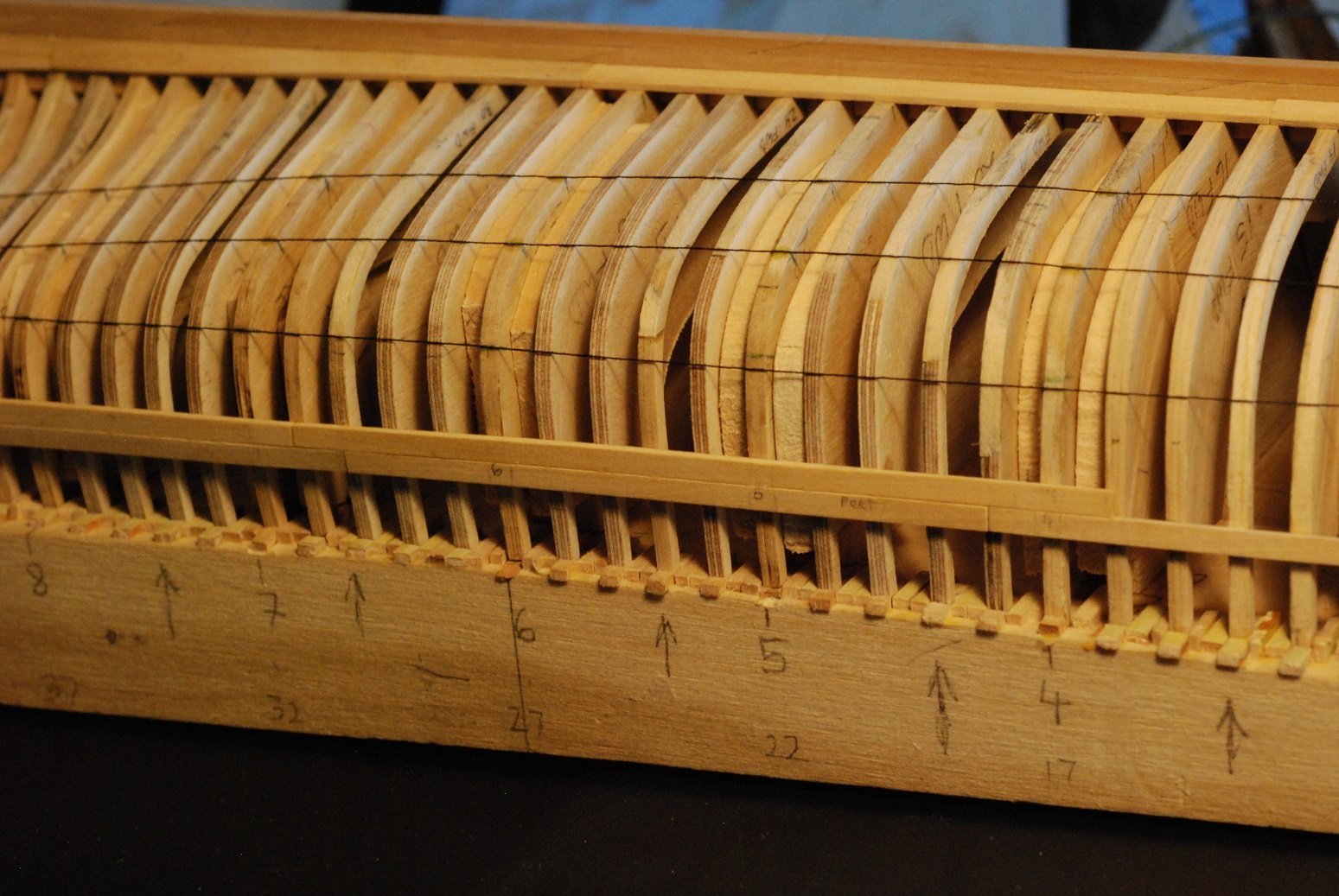
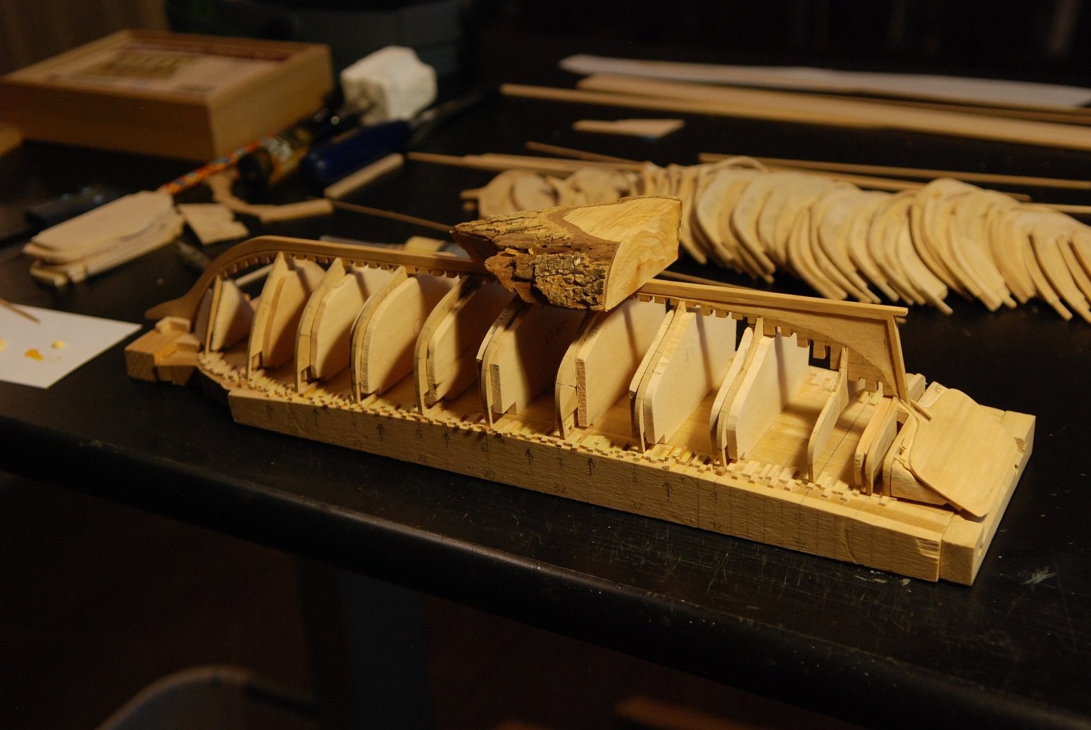
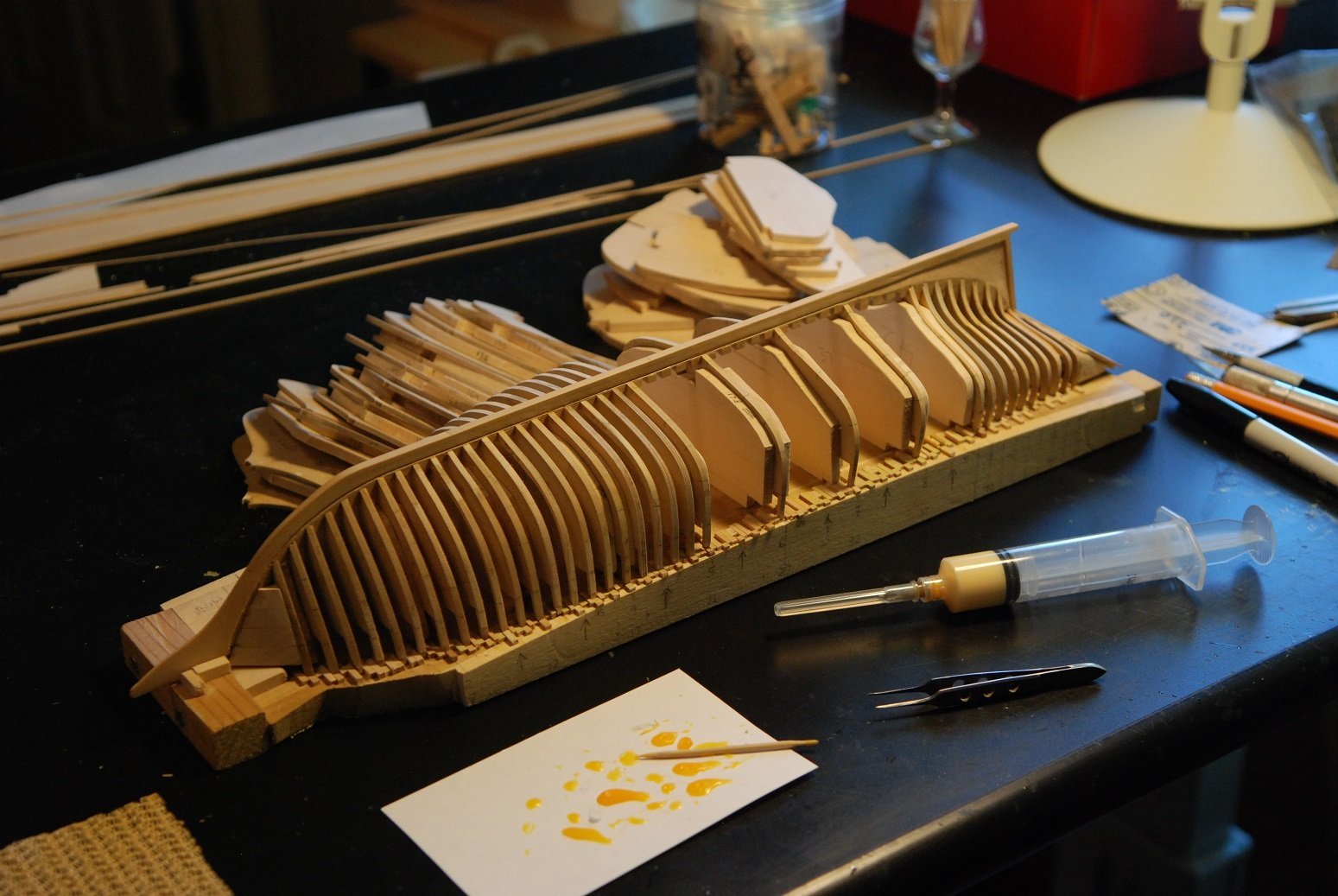
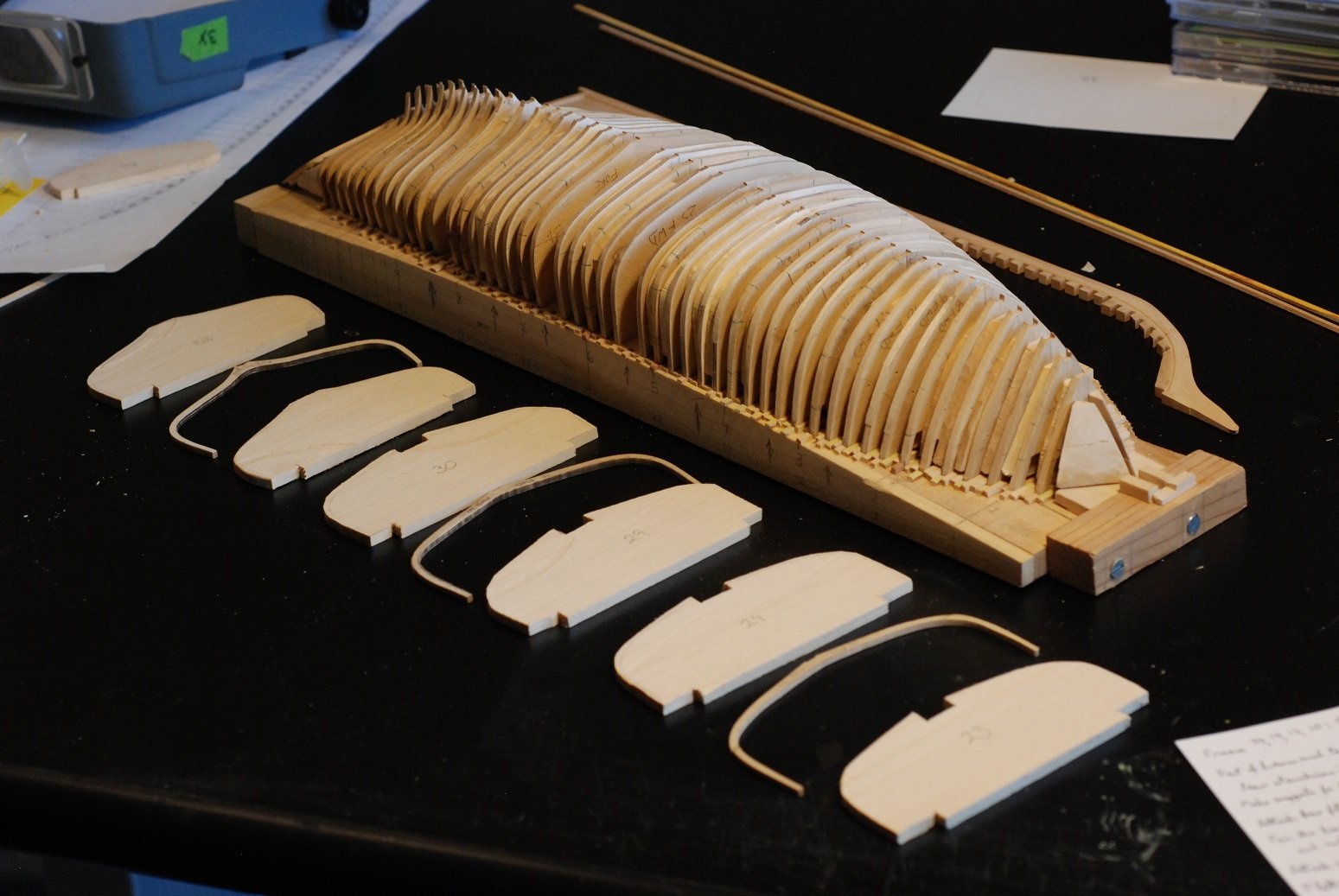
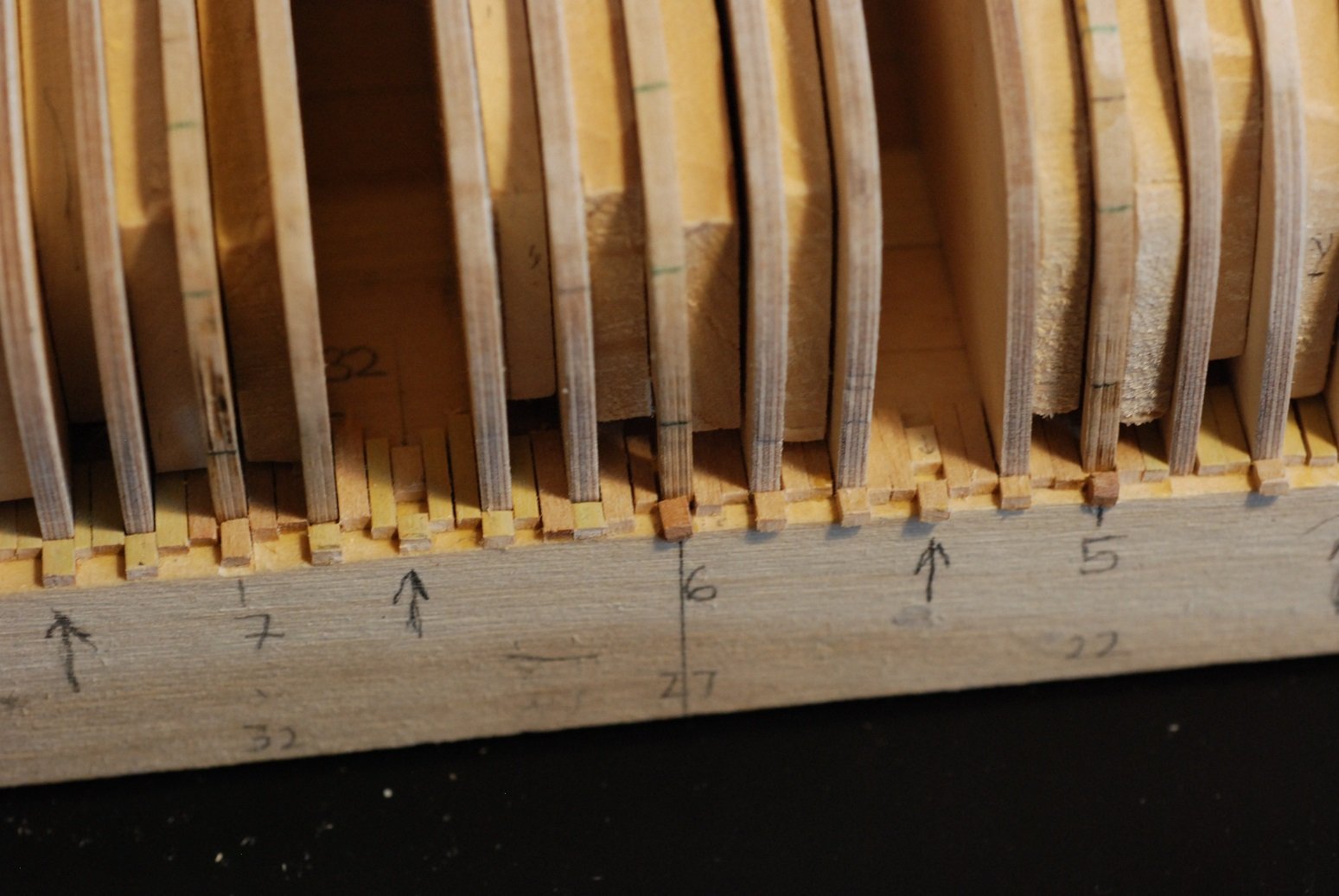
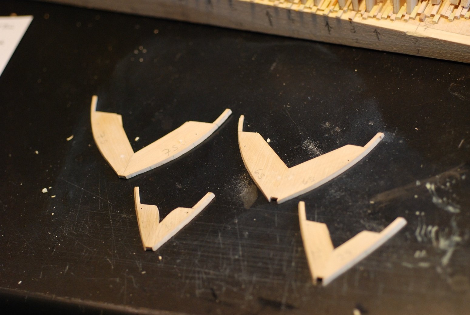
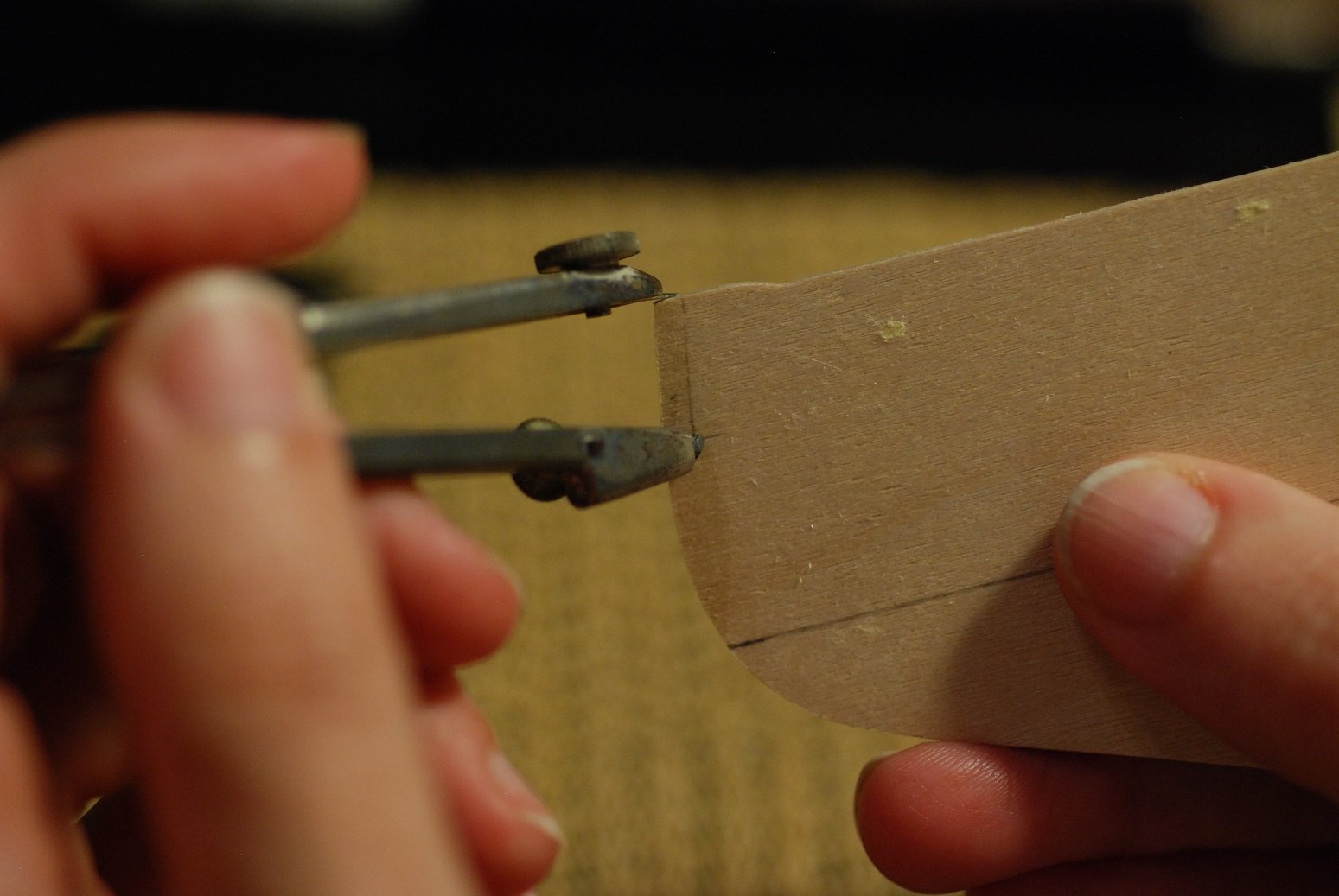
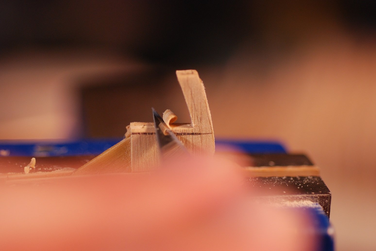
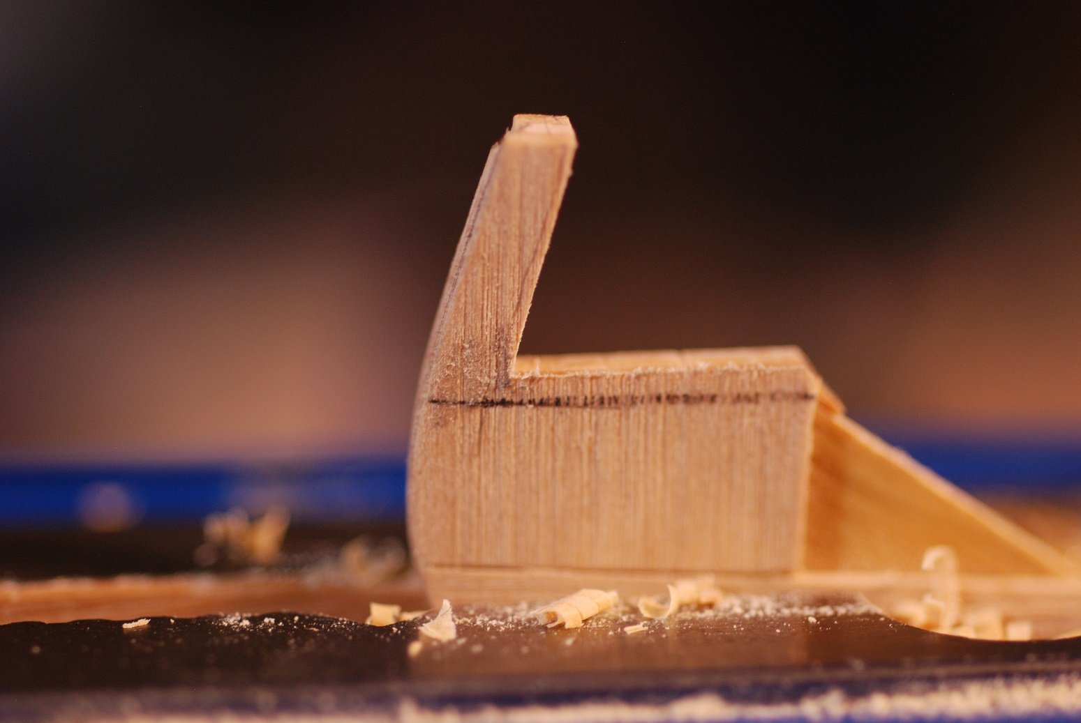
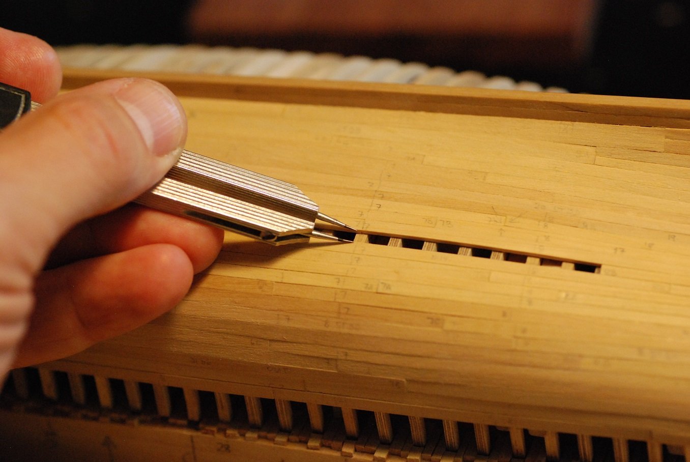
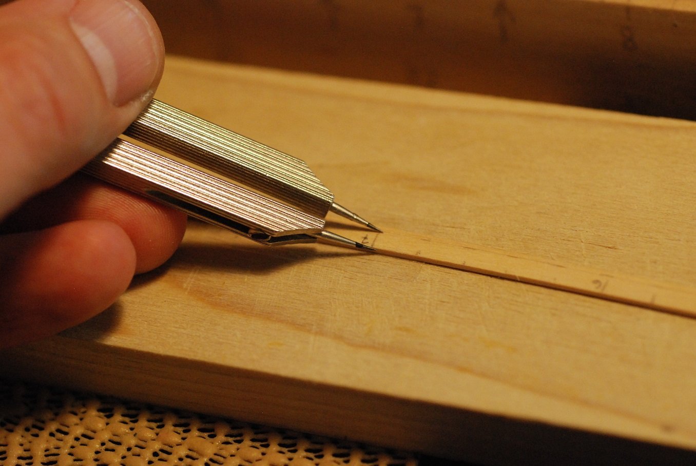
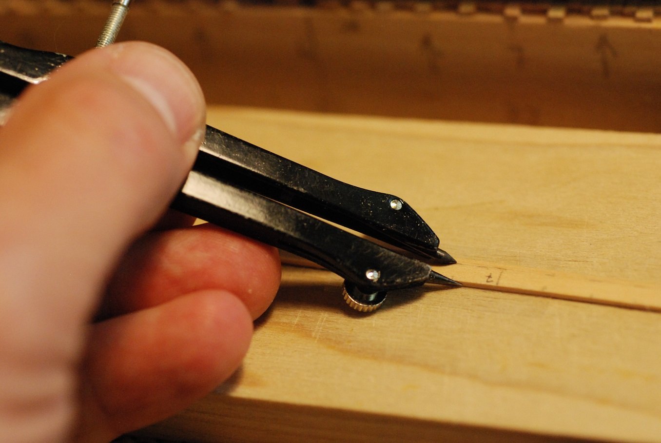
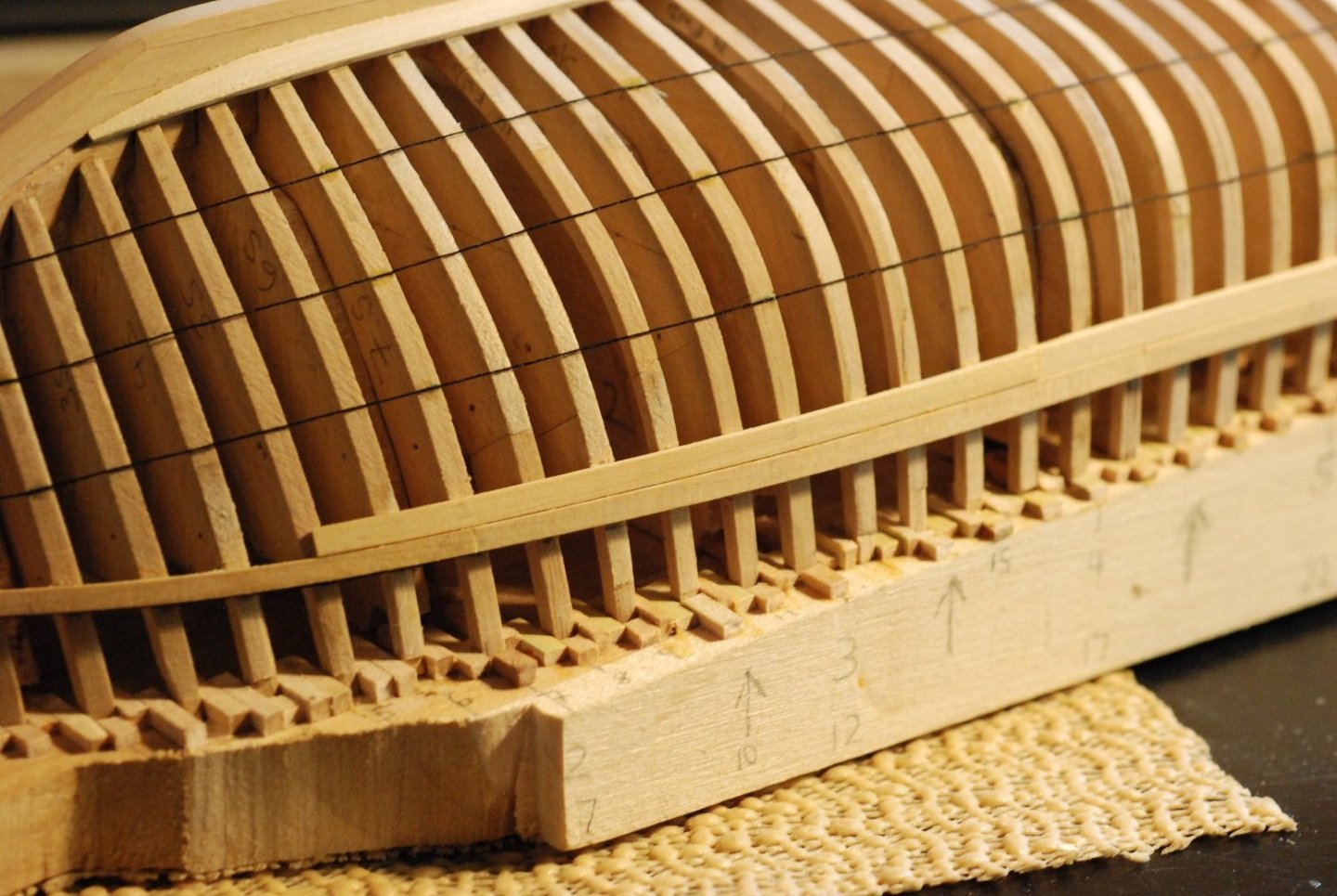
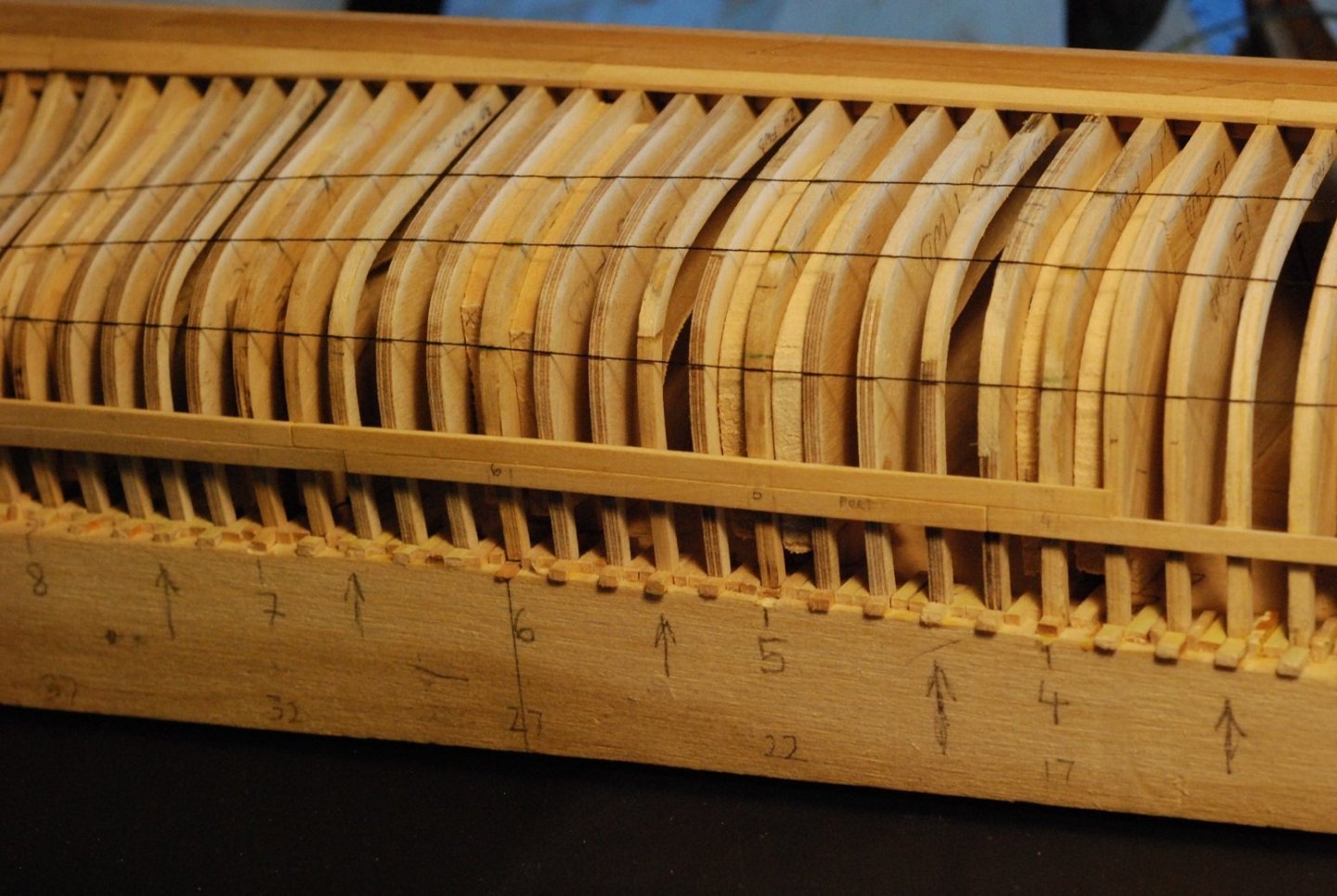
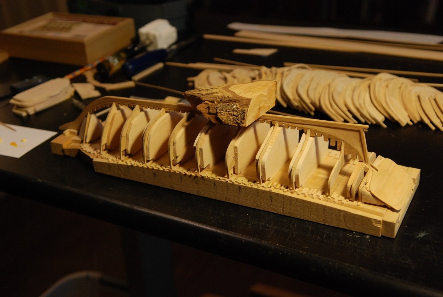
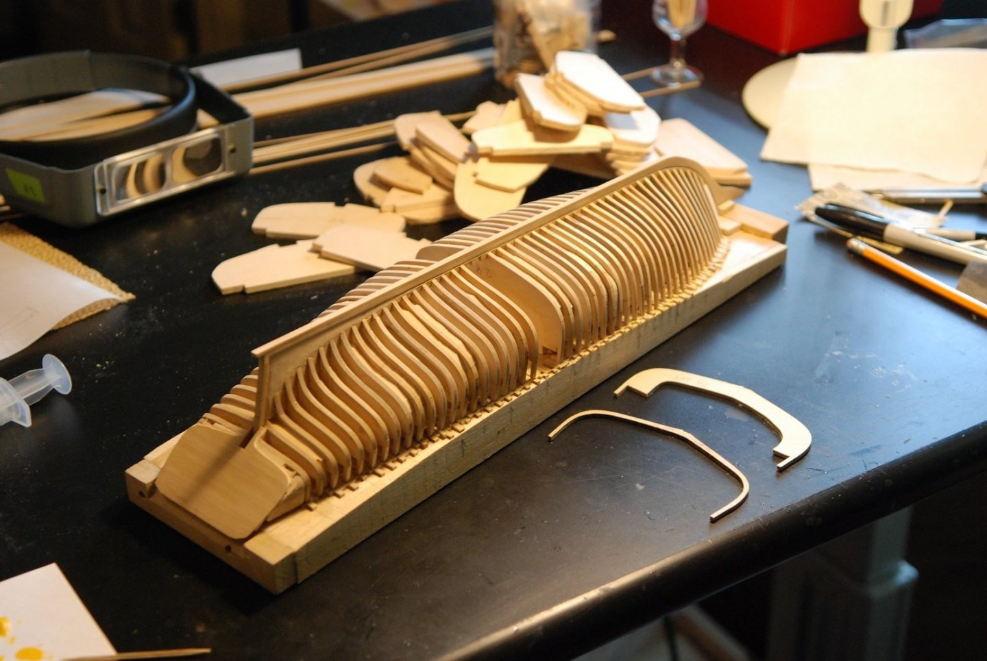
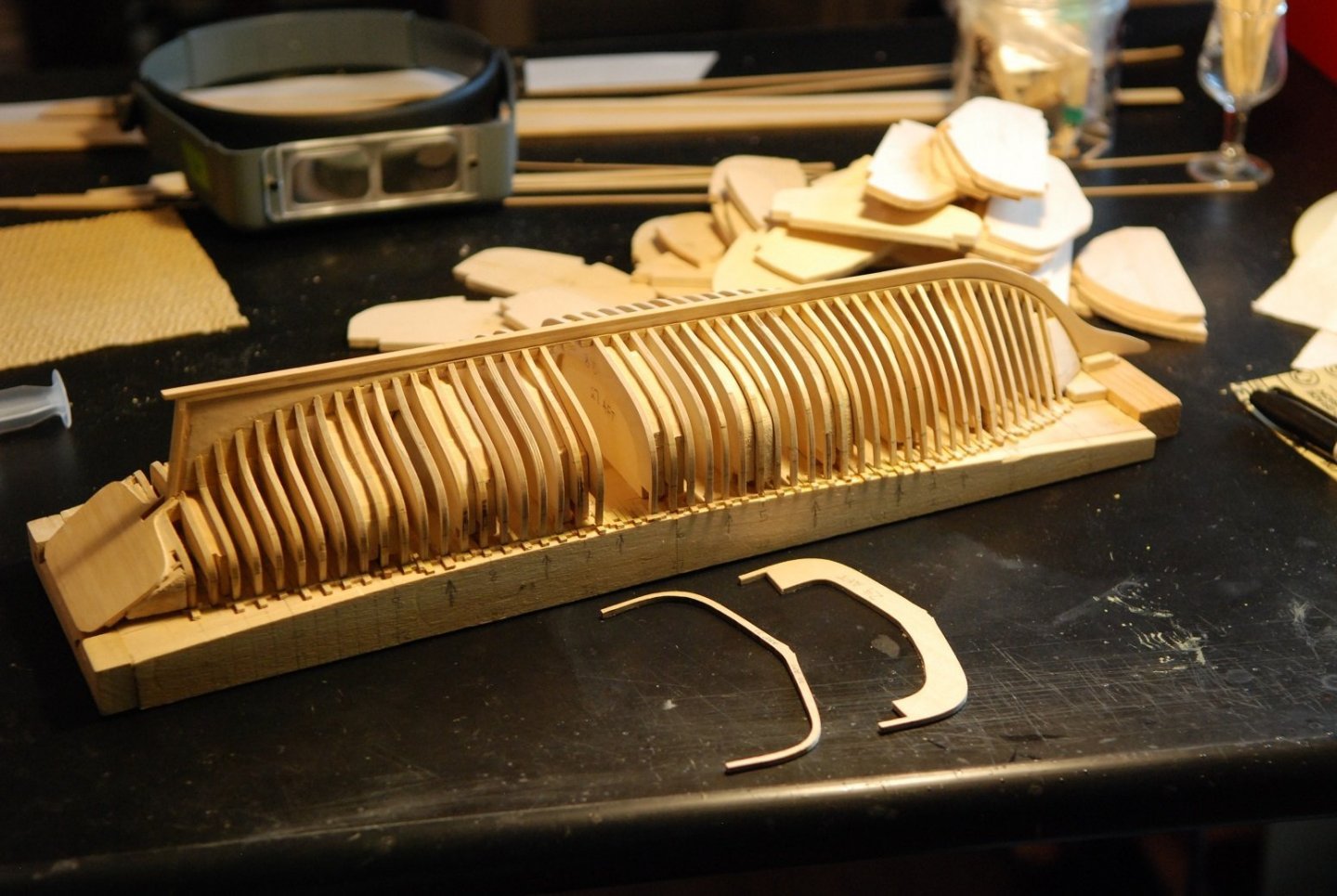
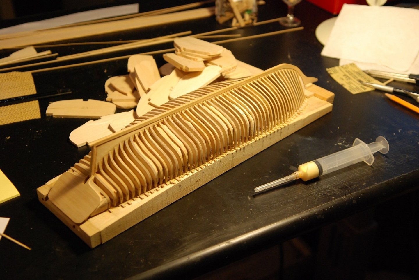
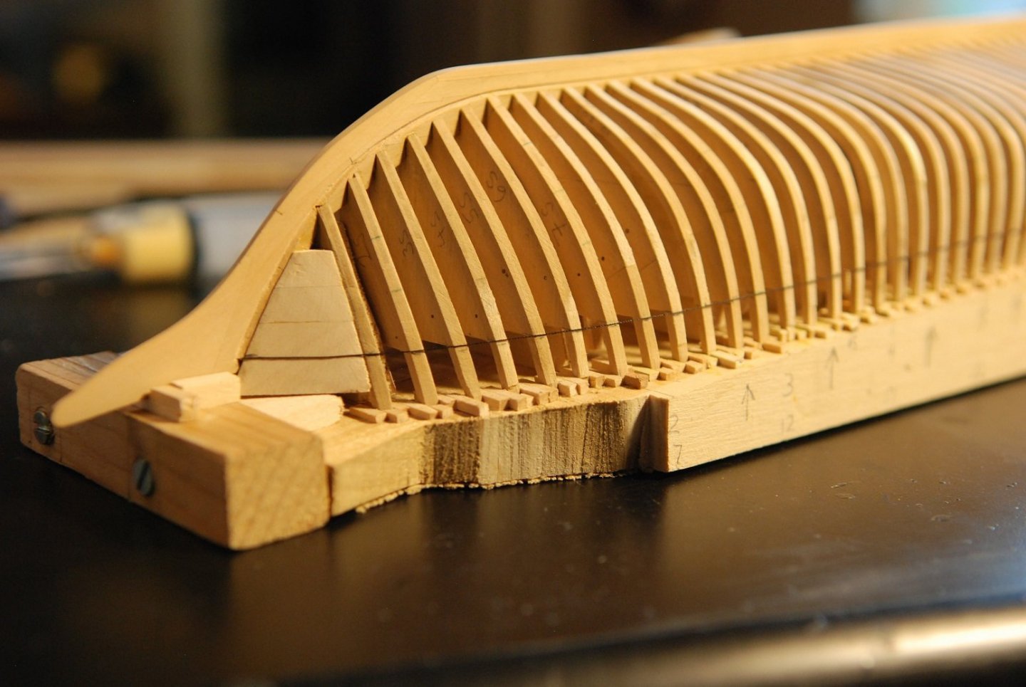
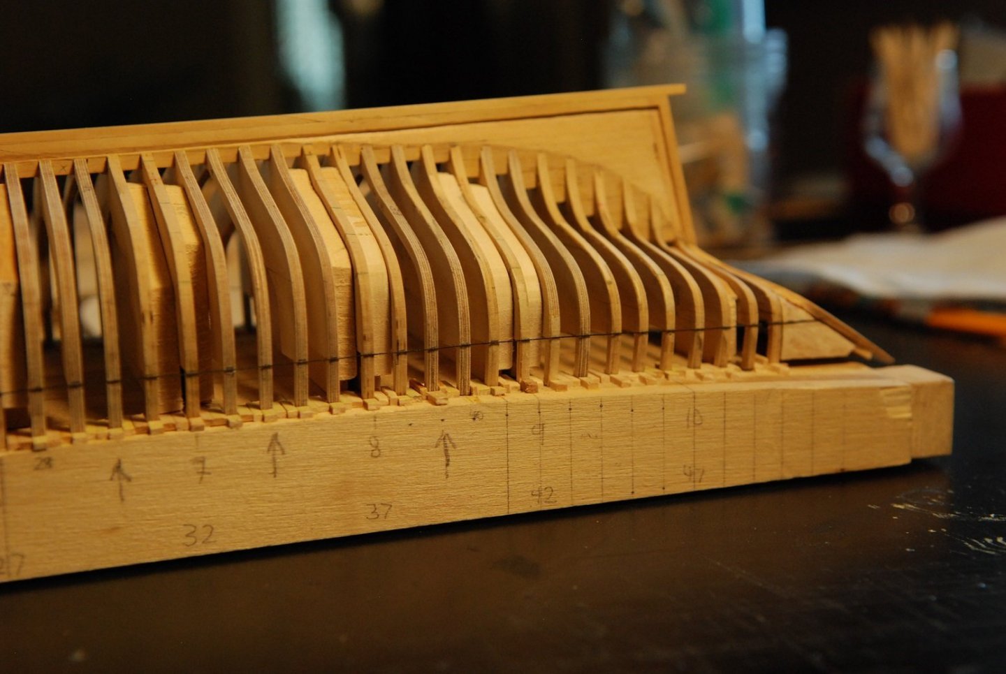
In getting prepared for assembling the frames to the keel, I realized I had some cleanup of the keel to do. Very slight imperfections in the thickness of the various keel parts meant that squeeze-out of glue from certain joints was apparent. And sanding wasn’t addressing these issues. So I used a razor blade to scrape the surface of each side of the keel, which appeared to bring things more into a flat surface and eliminated much of the squeeze-out you can see here. That’s better. So, once again, here is how things look, with most of the bulkheads on the building board. I have seven forward frames pulled out from the bow area to show that four of them have their bulwark stanchions carved into them, while the other 3 don’t have them yet. The point of building the model with all of these bulkheads (rather than just 11 bulkheads, one at each station) is so that I can leave part of the hull unplanked and show the internal structure of the boat. But I figured out very quickly that to make each frame to its proper, scaled molded dimension would result in a bunch of frames that are extremely fragile, even when glued to the keel and supported by the baseboard. So my plan is to make approximately every fifth frame according to its proper scaled dimensions while leaving the remaining 80% of frames essentially as bulkheads. I will plank up the boat like that, omitting certain planks on one side of the hull during the process. Then, once it is planked, I will invert the boat and remove a lot of bulkhead wood from at least the side that is unplanked, and bring those bulkheads down to the same dimensions as the ones shown in the picture above. Each of the frames shown above is flanked by filler blocks that are just large enough to keep these very thin frames in their proper positions, while not interfering with the process of fairing the overall hull shape. The arrows indicate the location of the frames with properly molded dimensions. In addition, since the frames are so small and pliable, I have added extra wood shims to make sure that the tops of these frames are properly positioned and cannot move, either fore and aft or athwartships. It’s a risky process, the idea of building up this hull with the plan of carving out a lot of its internal support structure. But I figure that the hull planking will be a very solid structure since the planks are not only glued to the frames, but they are also edge glued to one another. Much like how plywood lapstrake construction of real, full-sized boats makes for a very stable structure that requires much less internal framing. I also worked on smoothing out the deadwood to accept the planking in a properly fair manner. Now I have to work on creating bulwark stanchions for each and every bulkhead, as these will show on the final model. The stanchions have a consistent width of 3/32” on each face. A compass was used to mark out the width on both faces of each bulkhead. My wife’s lovely hands modeling the technique for me while I take the pictures! The height of each stanchion should be a consistent 7/16”, representing the distance between the bottom surface of the covering board to the undersurface of the caprail, as represented on the builder’s plans. This is how things should end up looking. So here is a frame in the vise, with the pencil marks evident. This frame is laminated castello, while some of the frames are 3/32” thickness fir plywood. I am impressed by how strong the laminated frames are. Even so, both the plywood and the laminated bulkheads experienced failures that would require re-gluing of the stanchion to the bulkhead. I cut as close as possible to the pencil line with a fresh X-acto blade. And I used a triangular file to get into the corner. Next I am going to actually start gluing bulkheads to the keel, and working out the garboard and sheer strakes! Gonna finally start getting the hull in shape.