jdbondy
-
Posts
341 -
Joined
-
Last visited
Content Type
Profiles
Forums
Gallery
Events
Everything posted by jdbondy
-
 What are you using for magnification? Optivisor or something similar? I know I would be using the microscope.
 -
I find myself sad that this chapter is coming to a close...but even more exciting chapters to follow!
-
Hi Gary, I was happily directed to this build log from a different log. I am making today's comment to make sure you are familiar with an article that appeared in the January/February 2023 edition of Wooden Boat, entitled "The Wizards of Stony Creek". It talks about Johnny Waters and his various boats (including oyster draggers) in the area of the Thimble Islands on the Connecticut coast. You seem to be someone who would be interested in the article. Enjoy!
-
Thanks, Druxey, Hubac, and Chris. Yes Chris, the manner was chosen because of the fact that at this scale, frames would be entirely too fragile to stand up to the planking process.
-
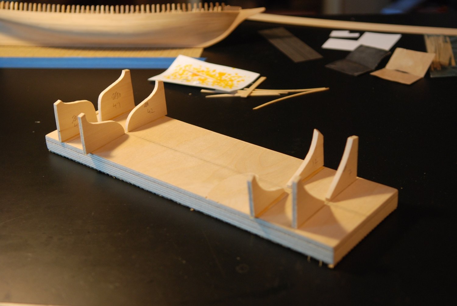
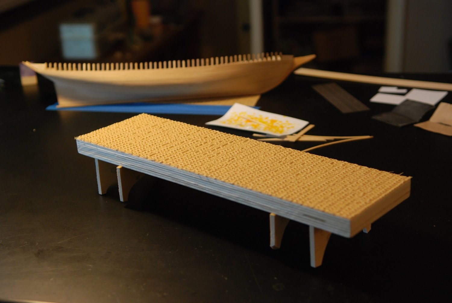
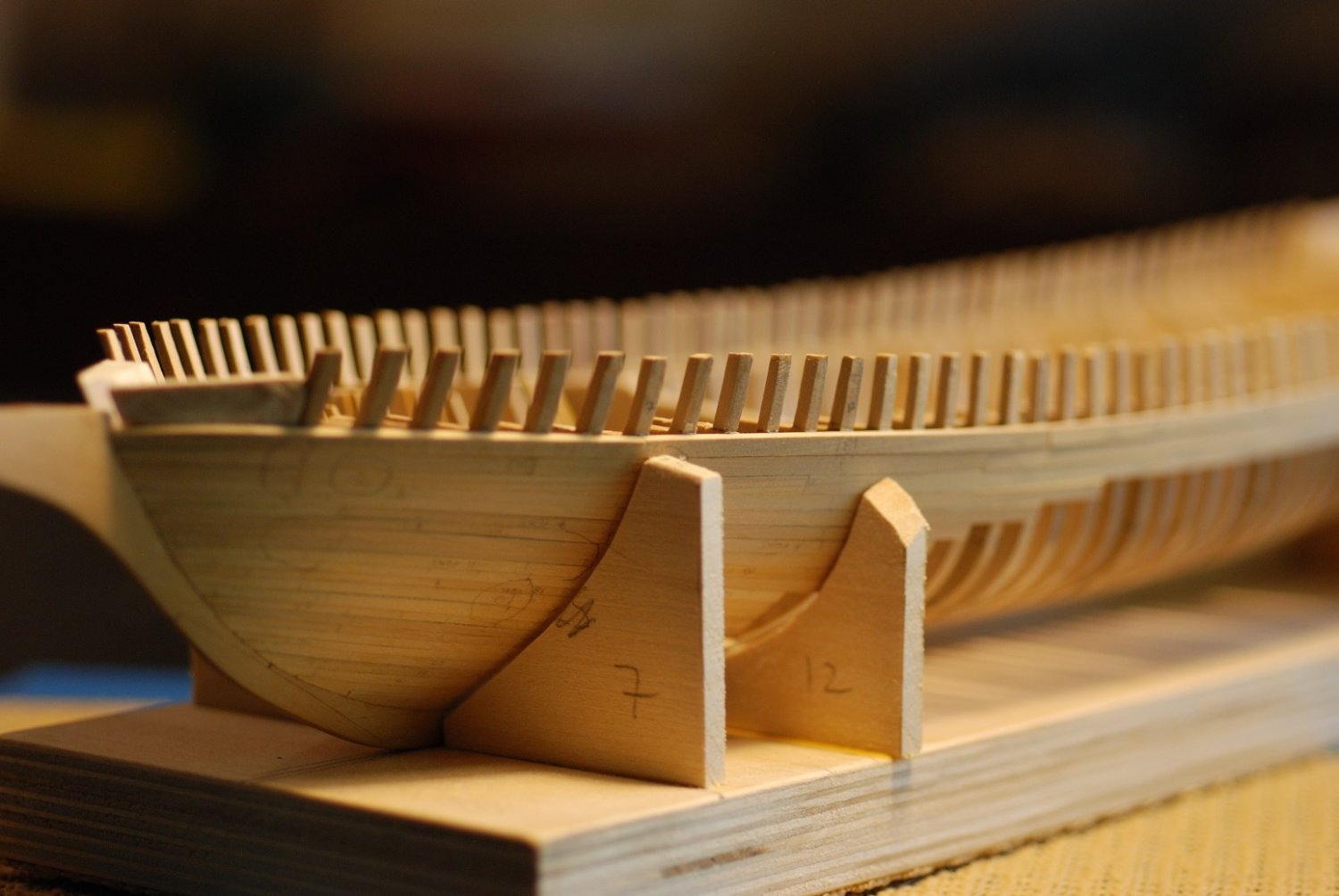
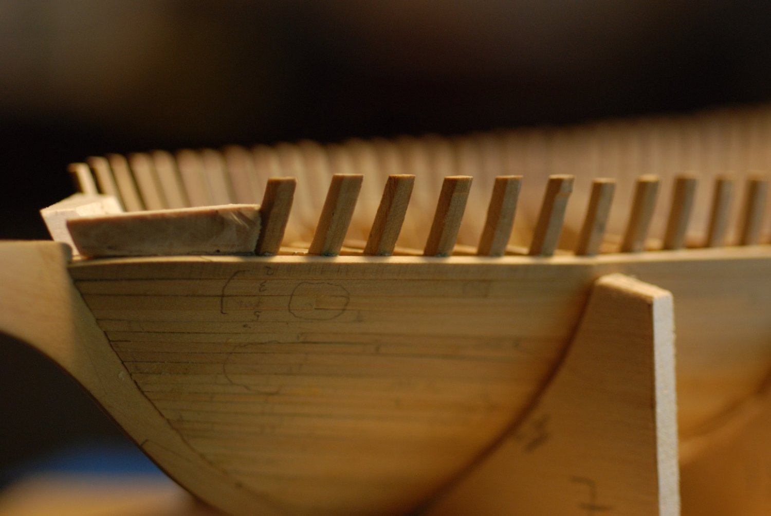
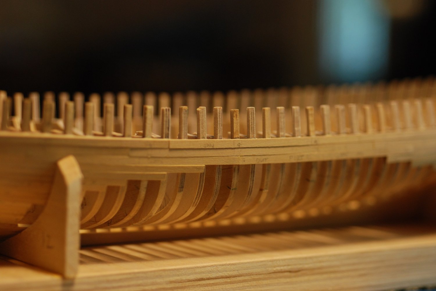
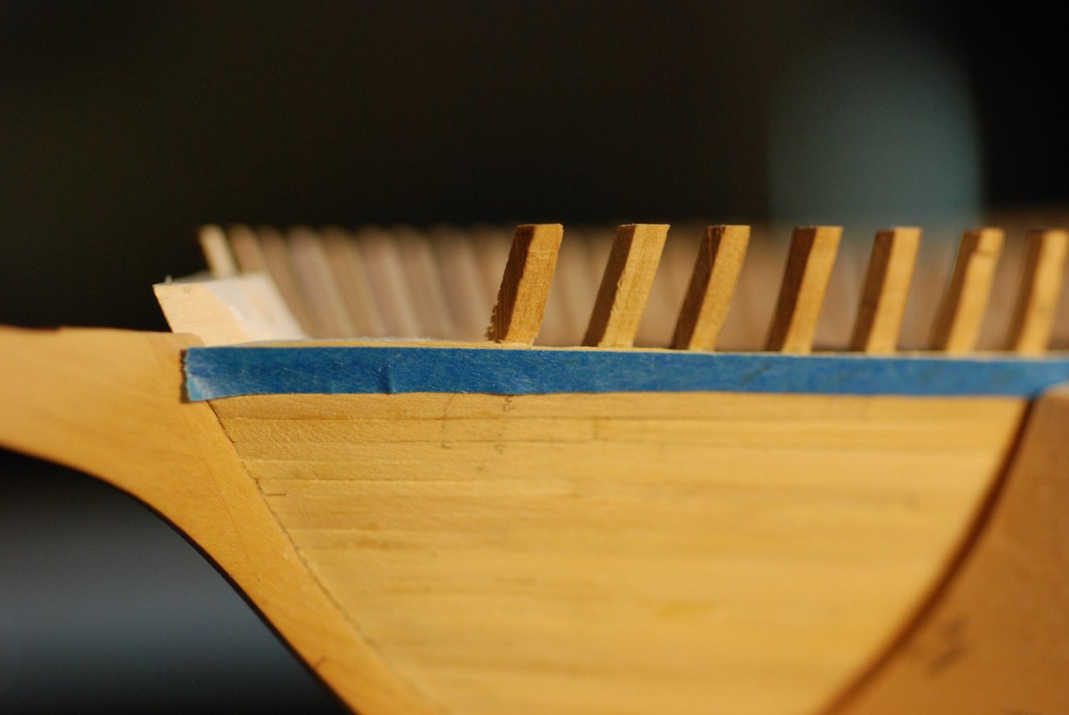
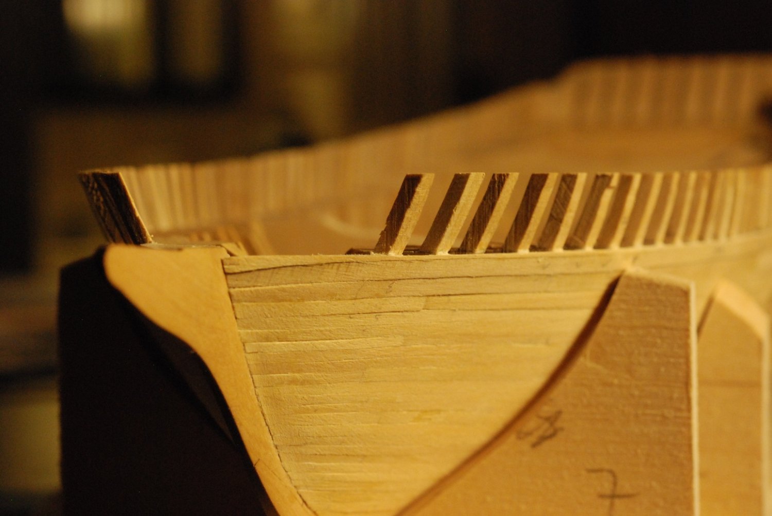
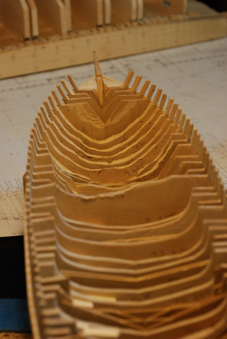
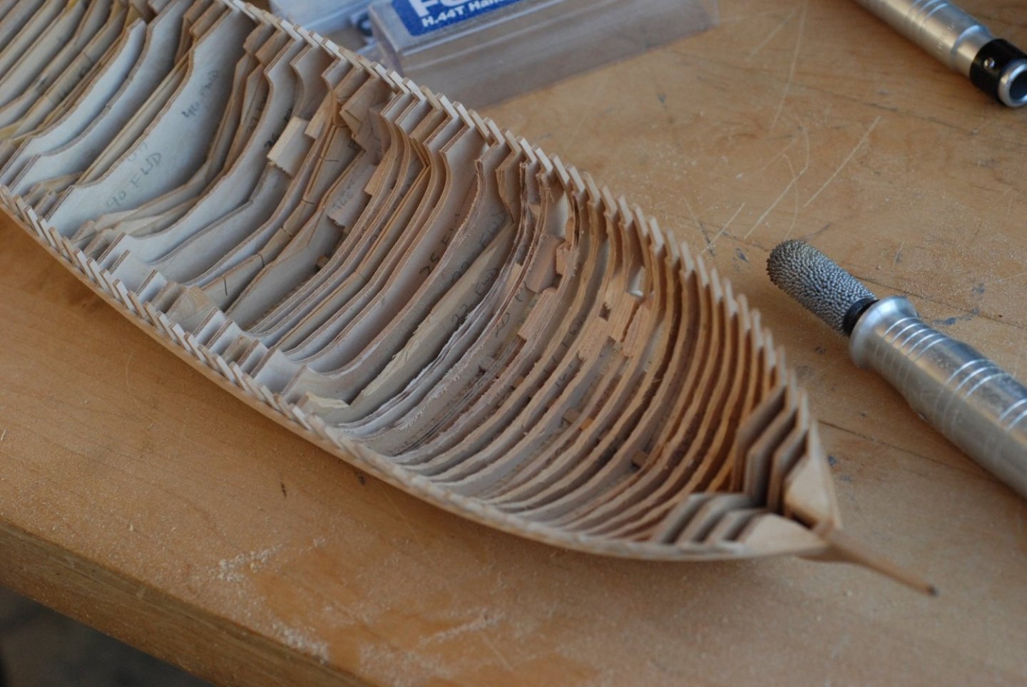
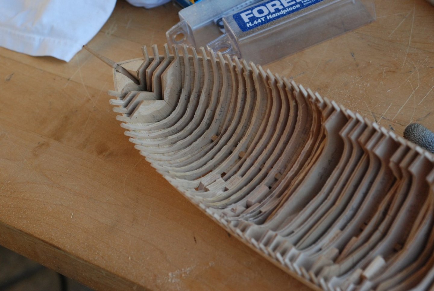
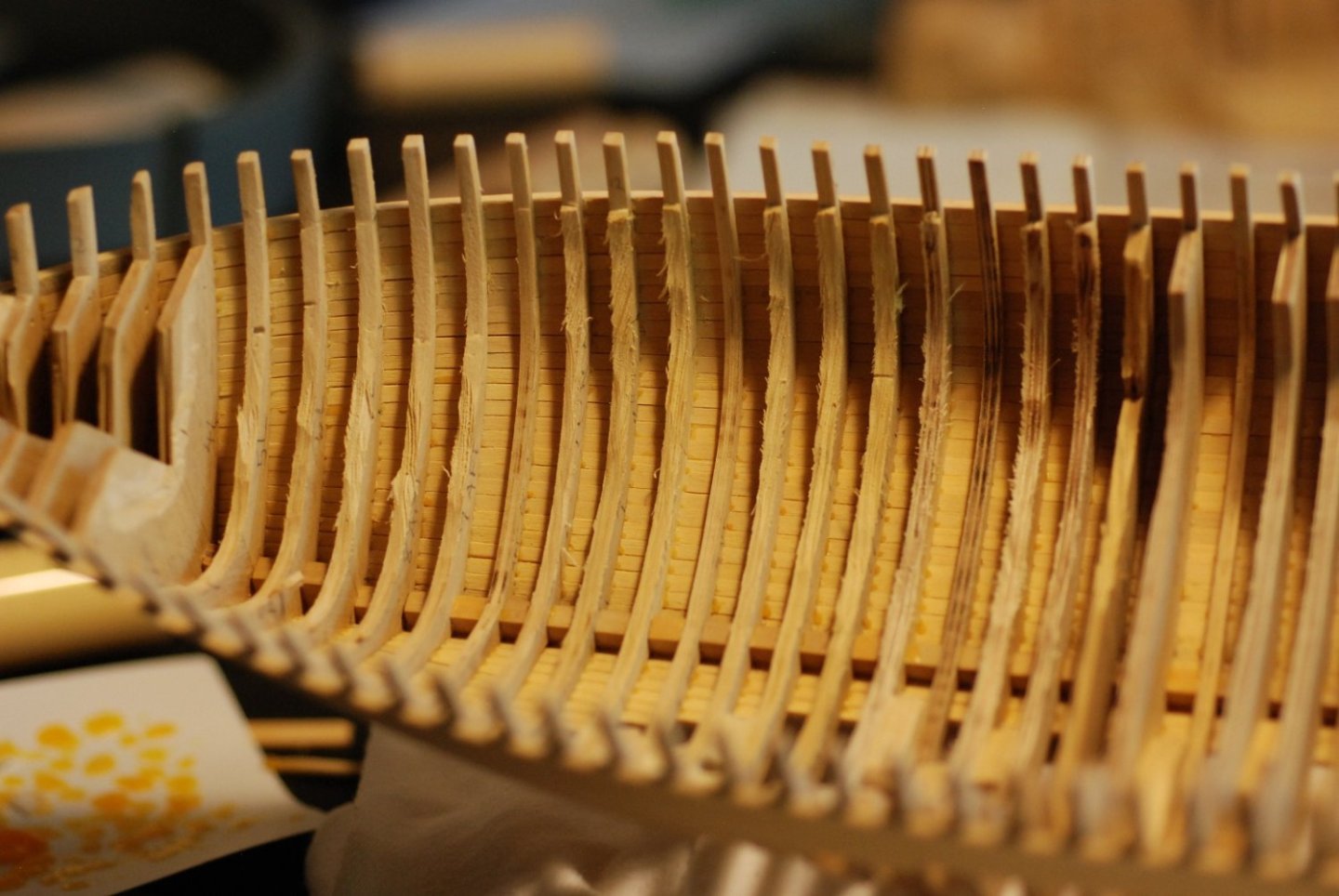
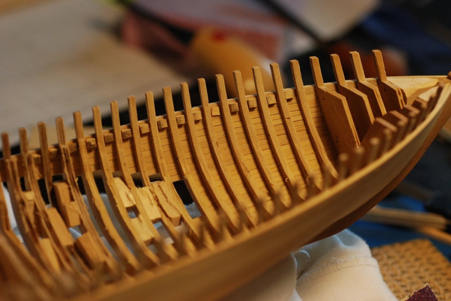
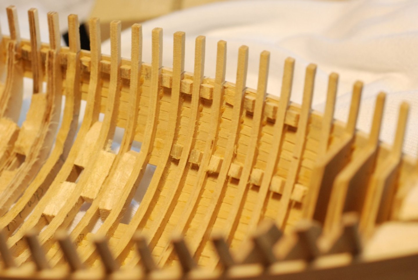
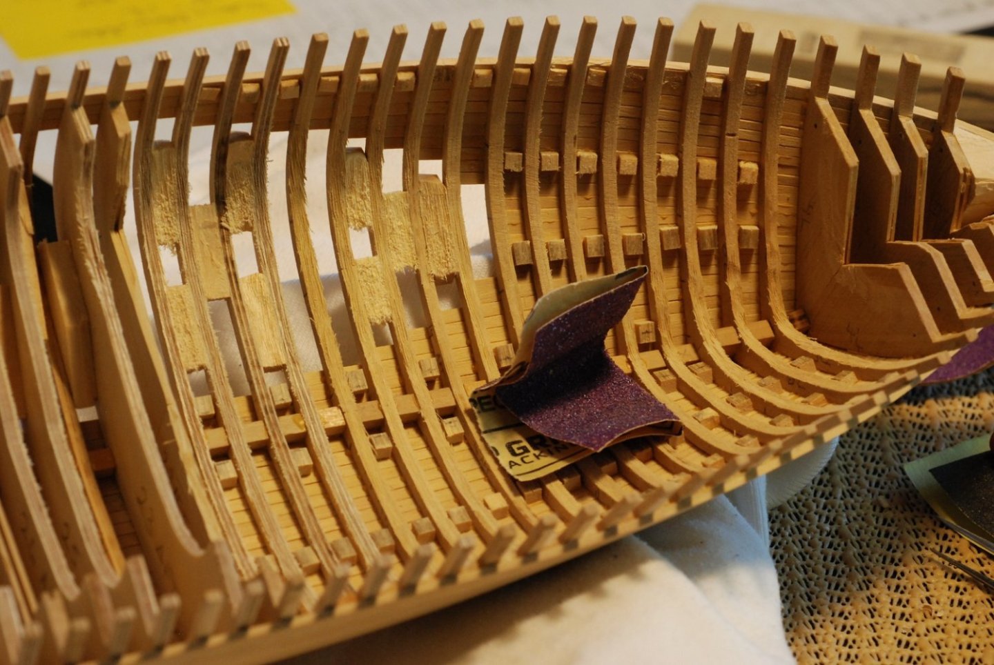
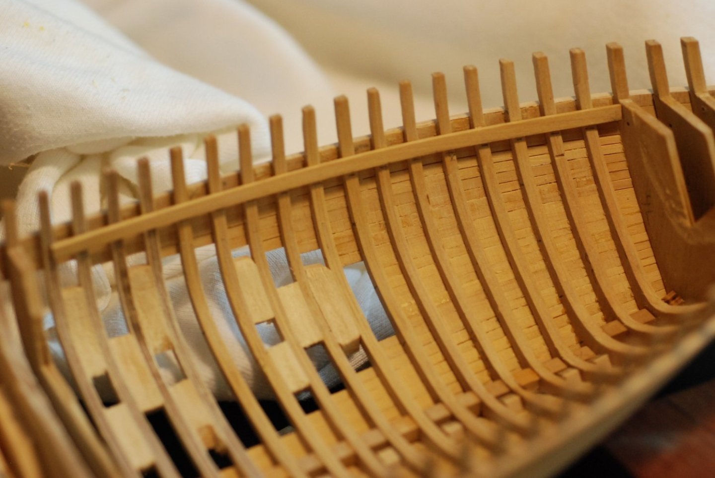
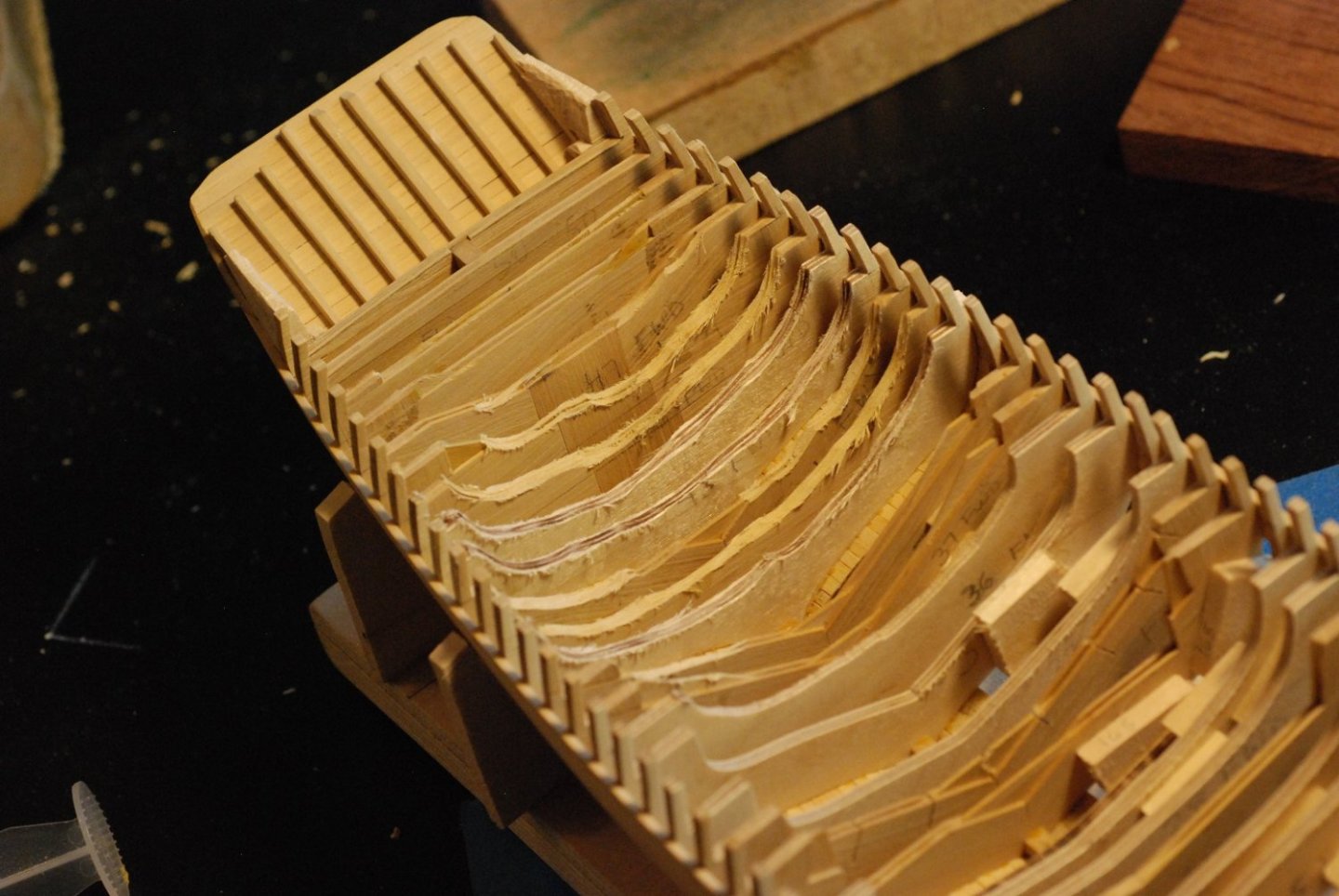
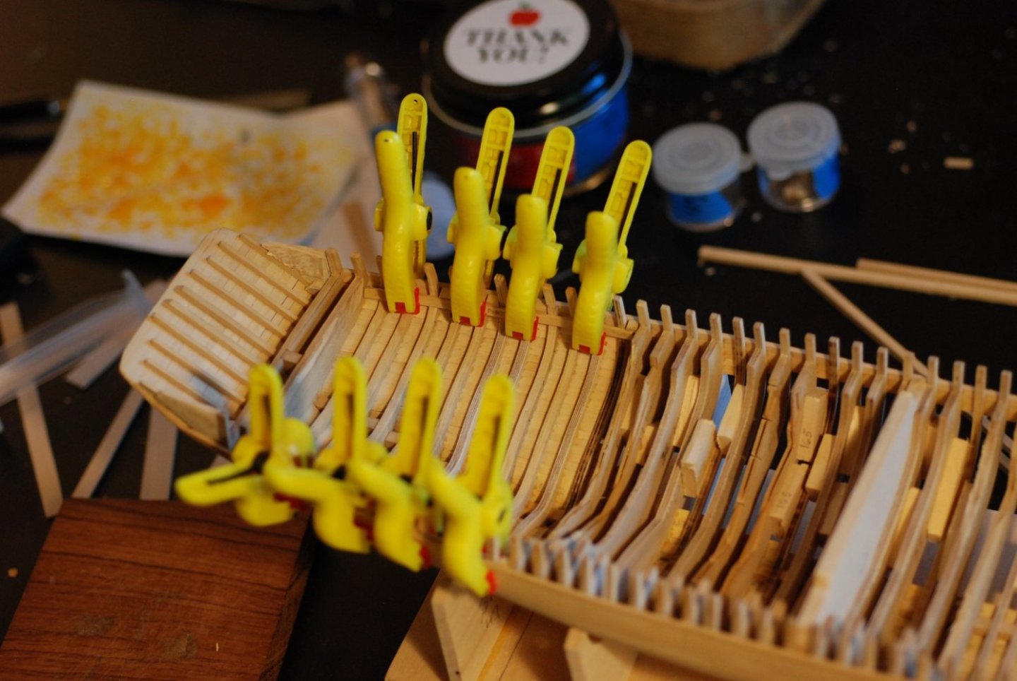
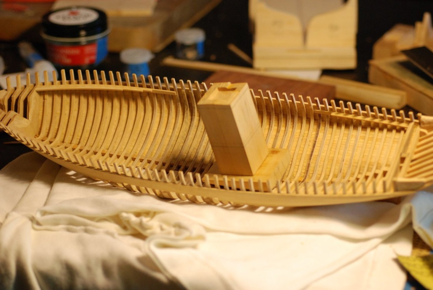
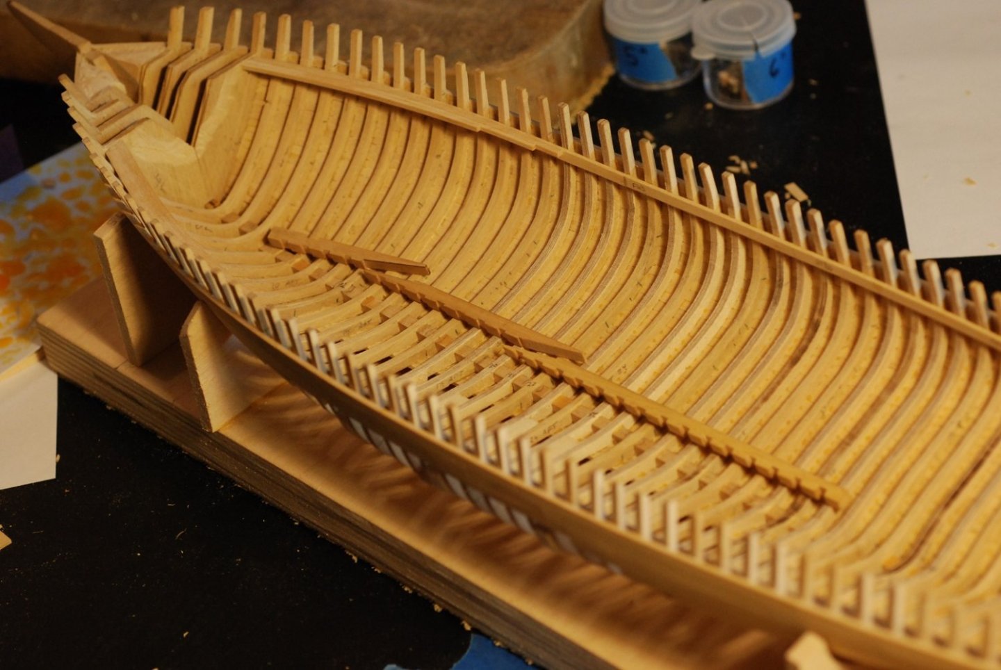
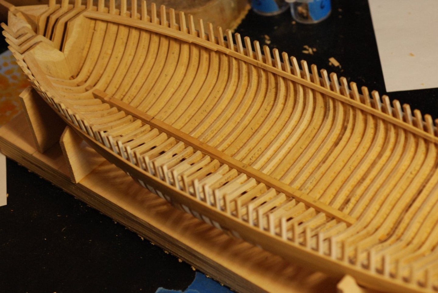
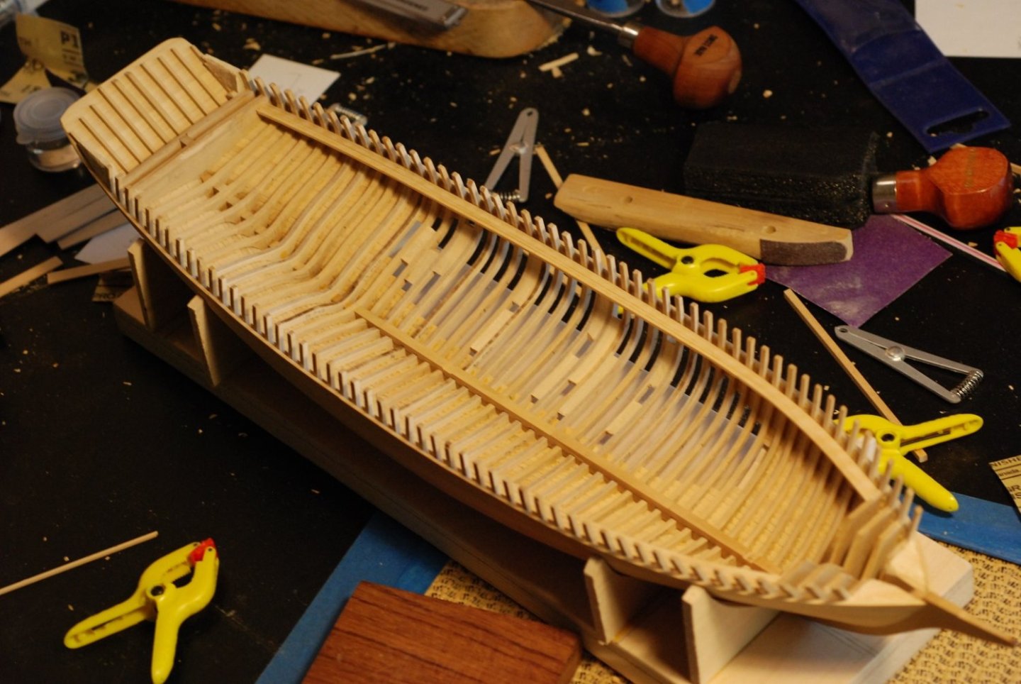
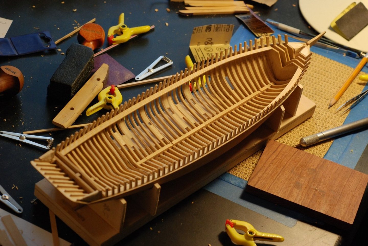
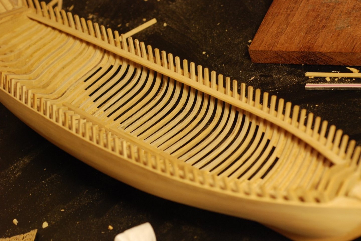
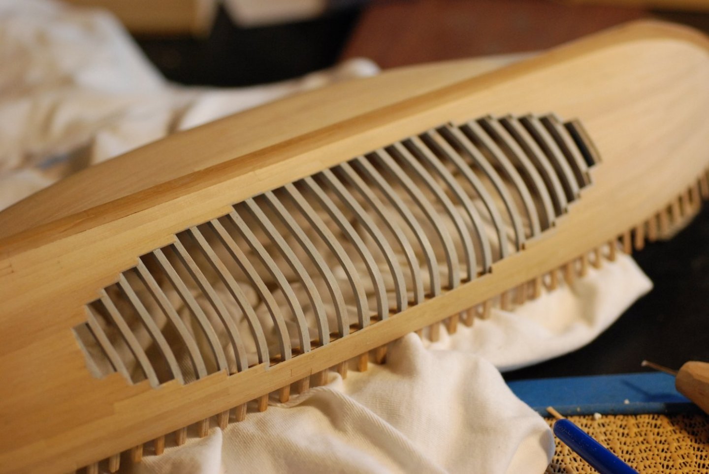
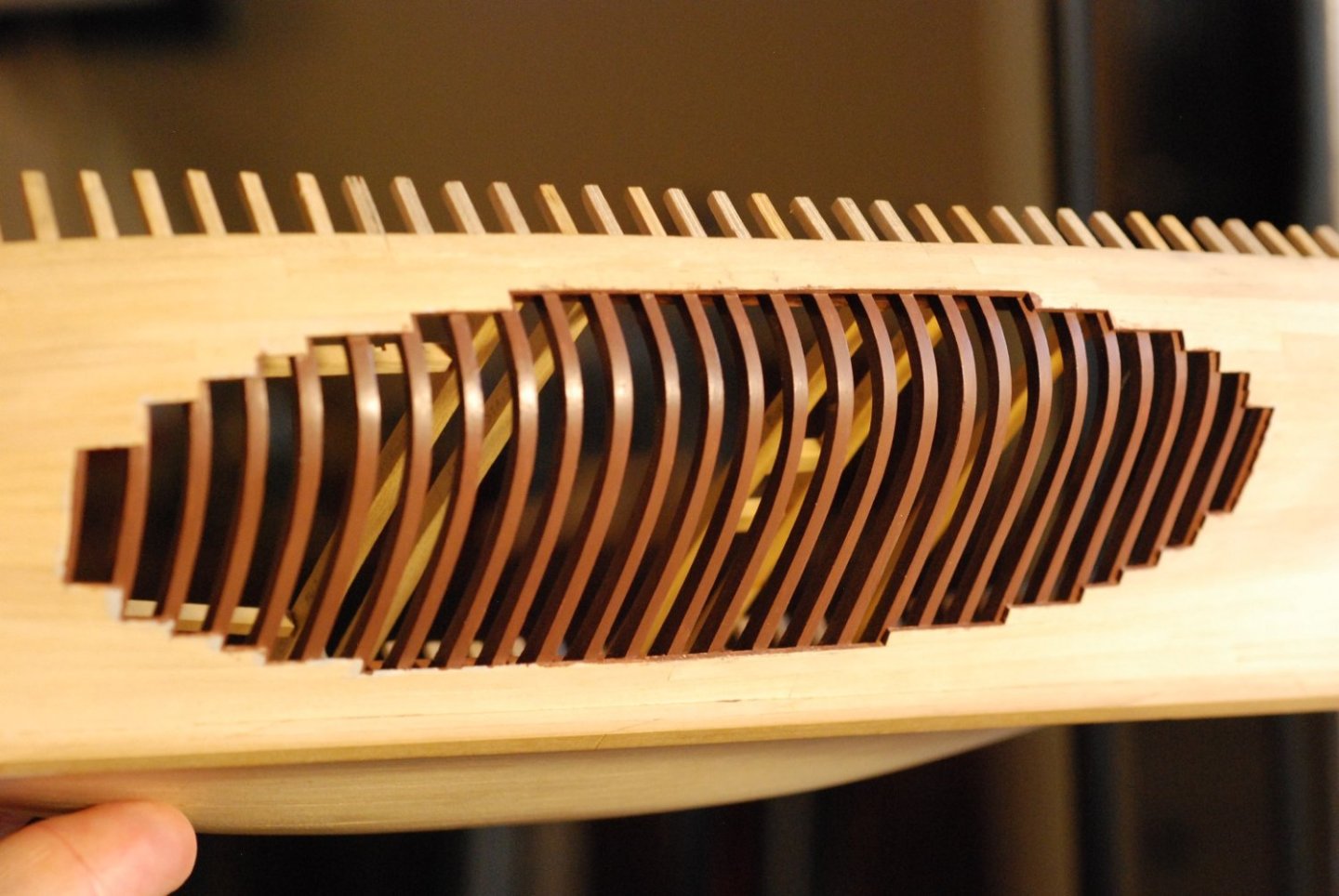
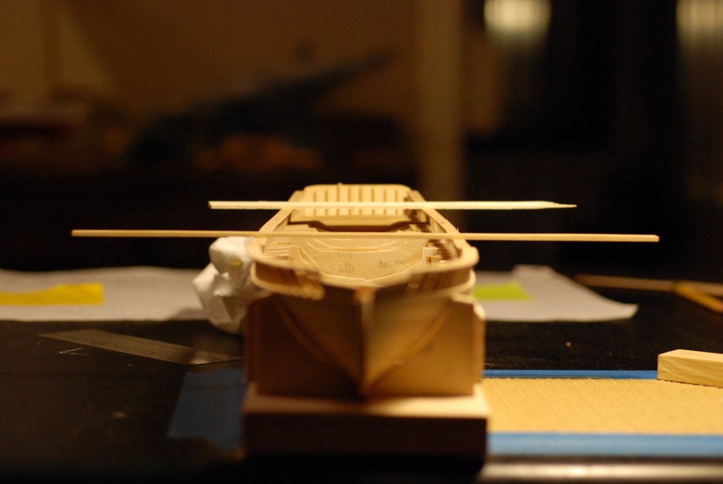
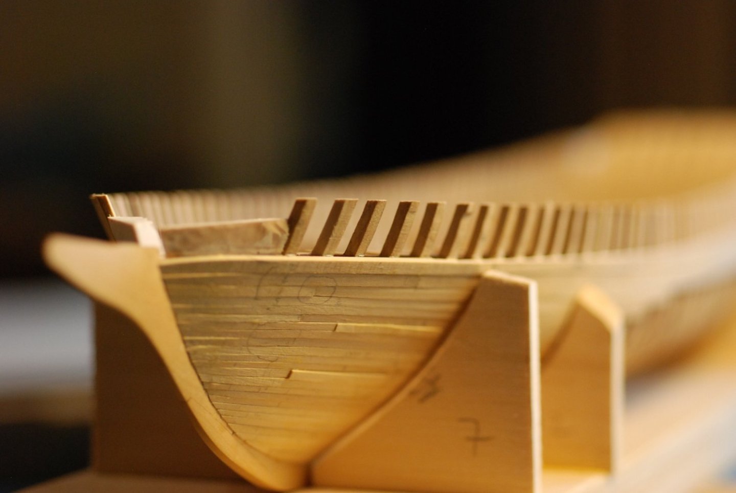
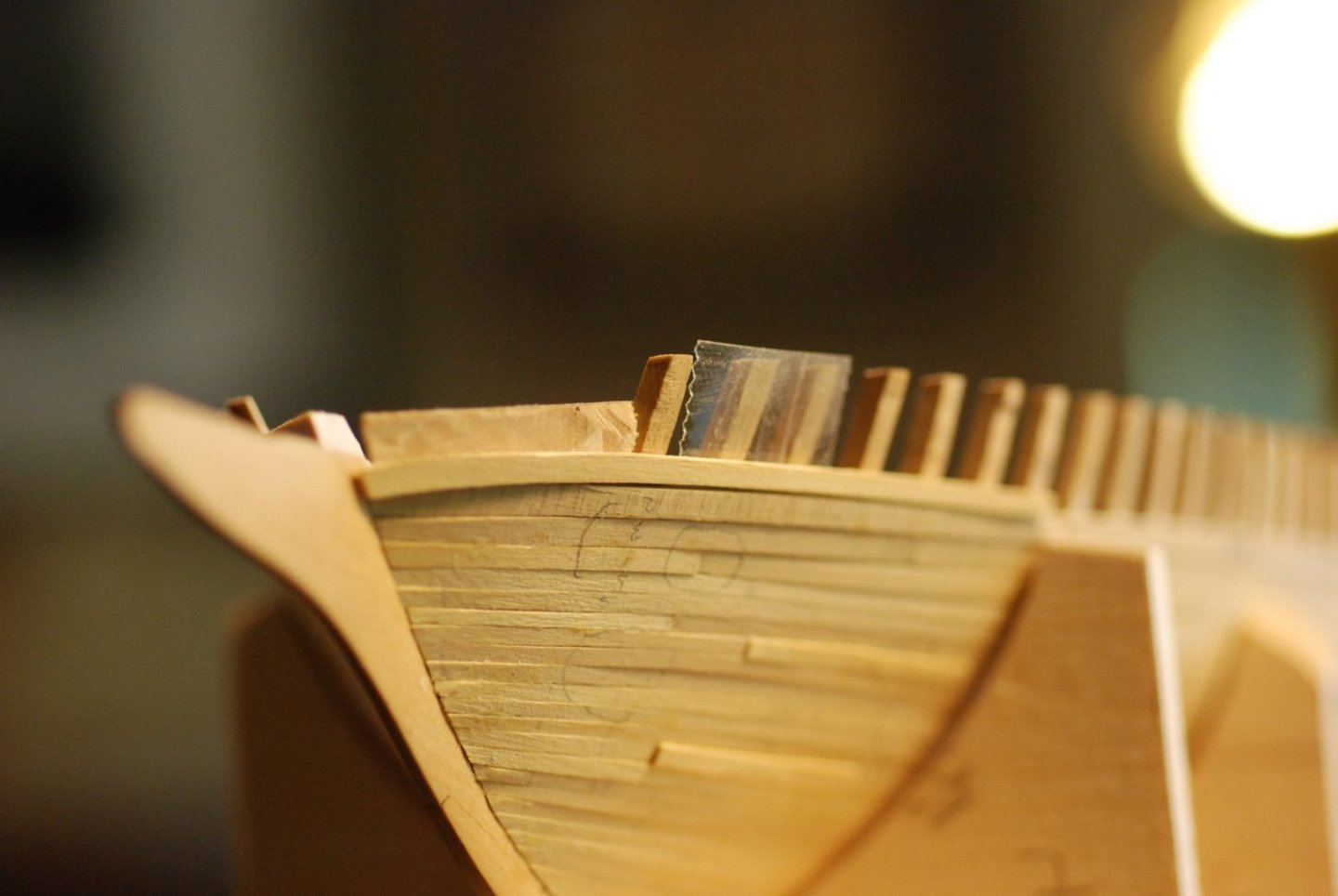
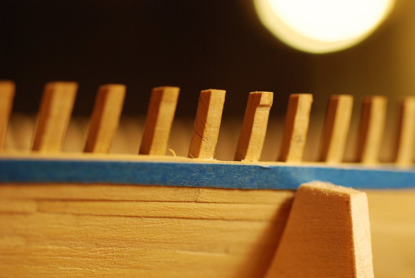
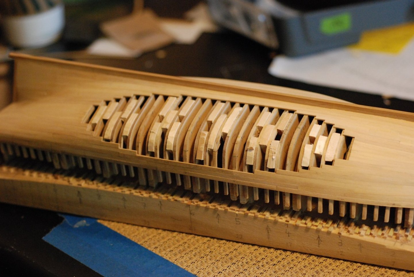
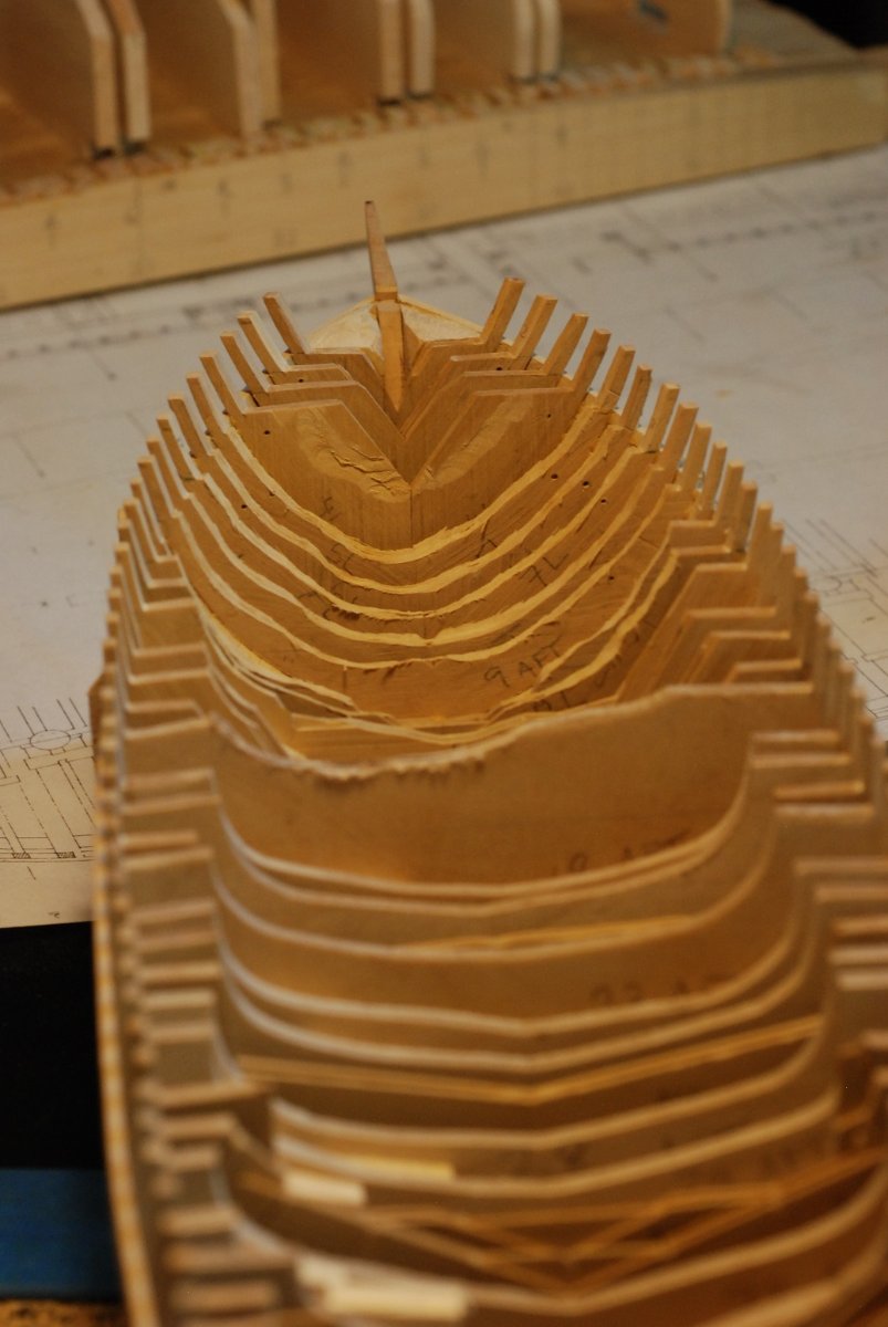
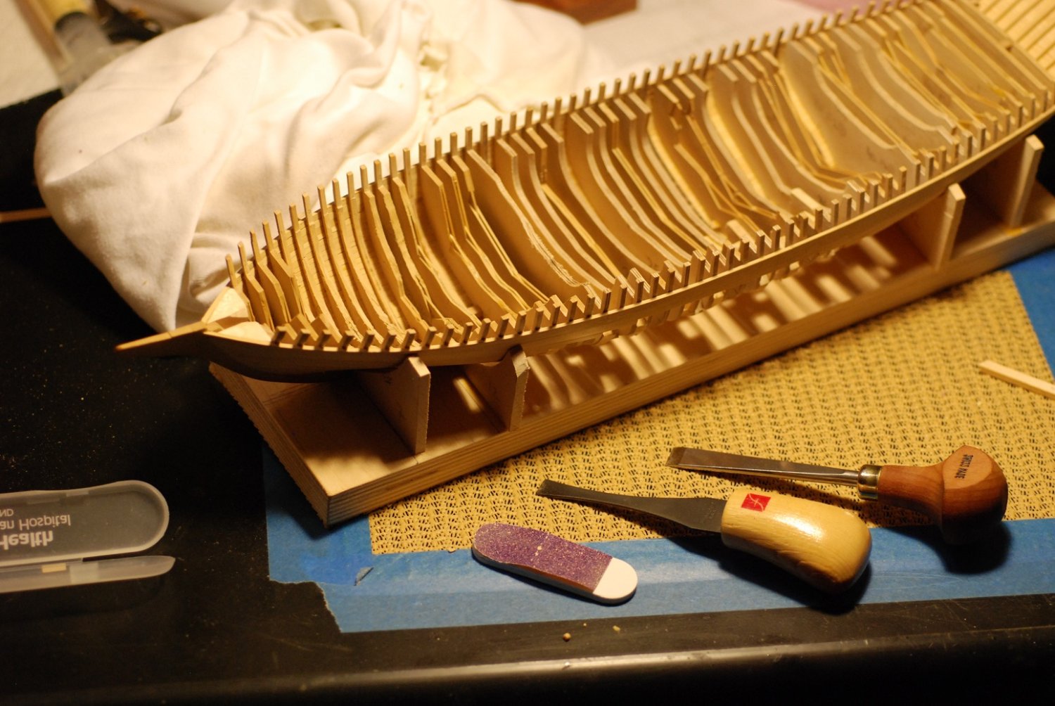
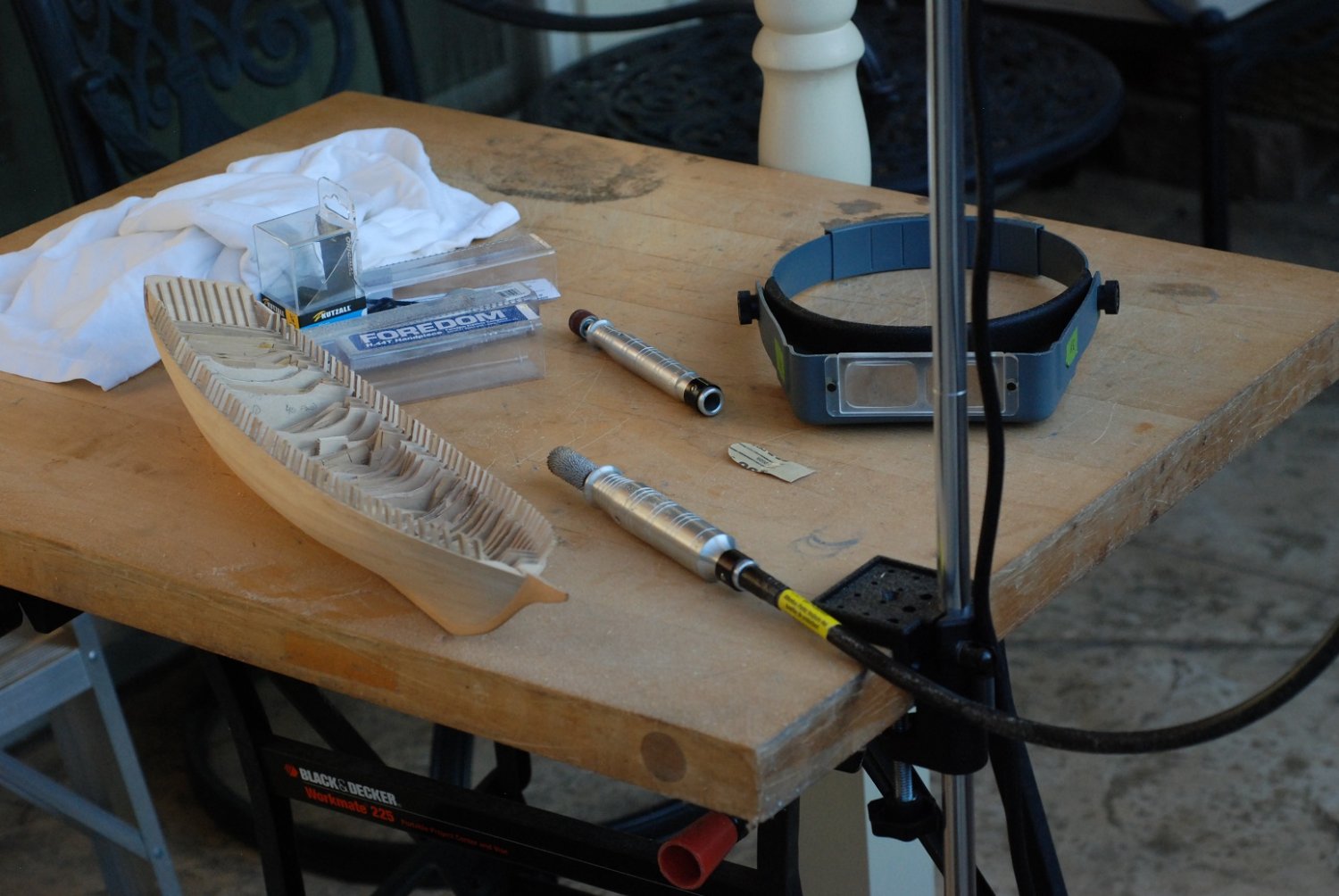
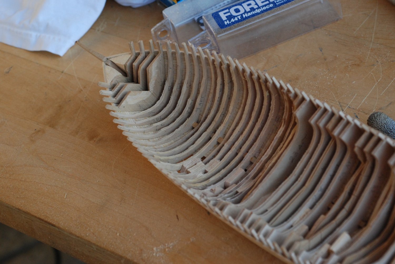
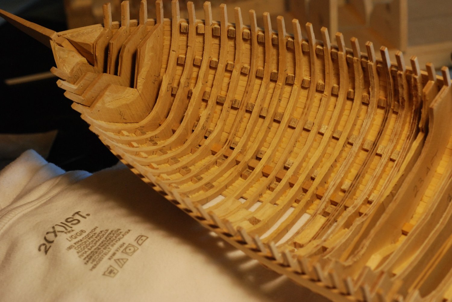
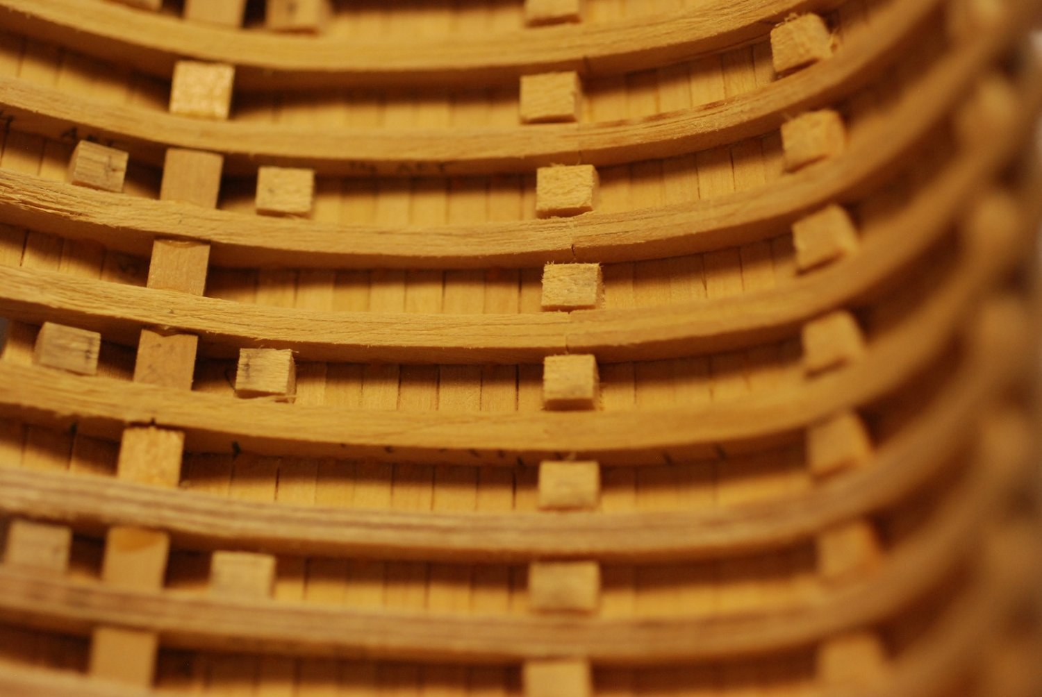
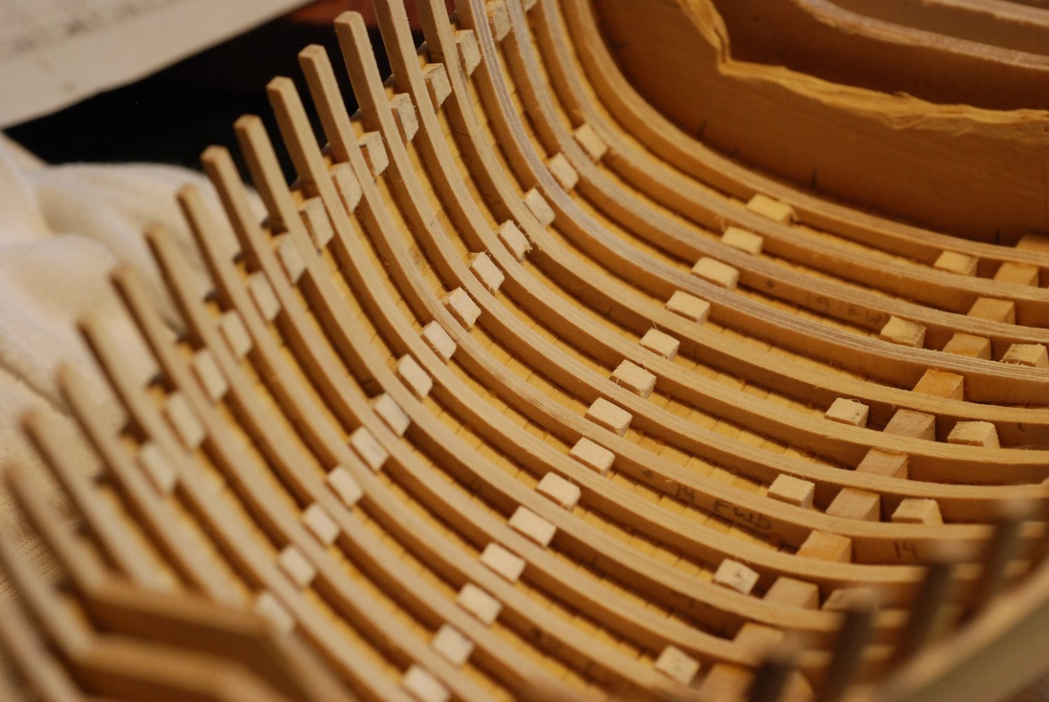
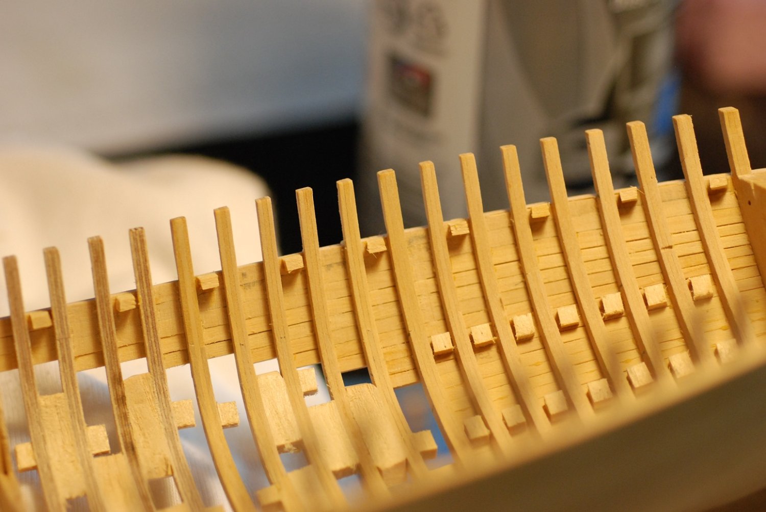
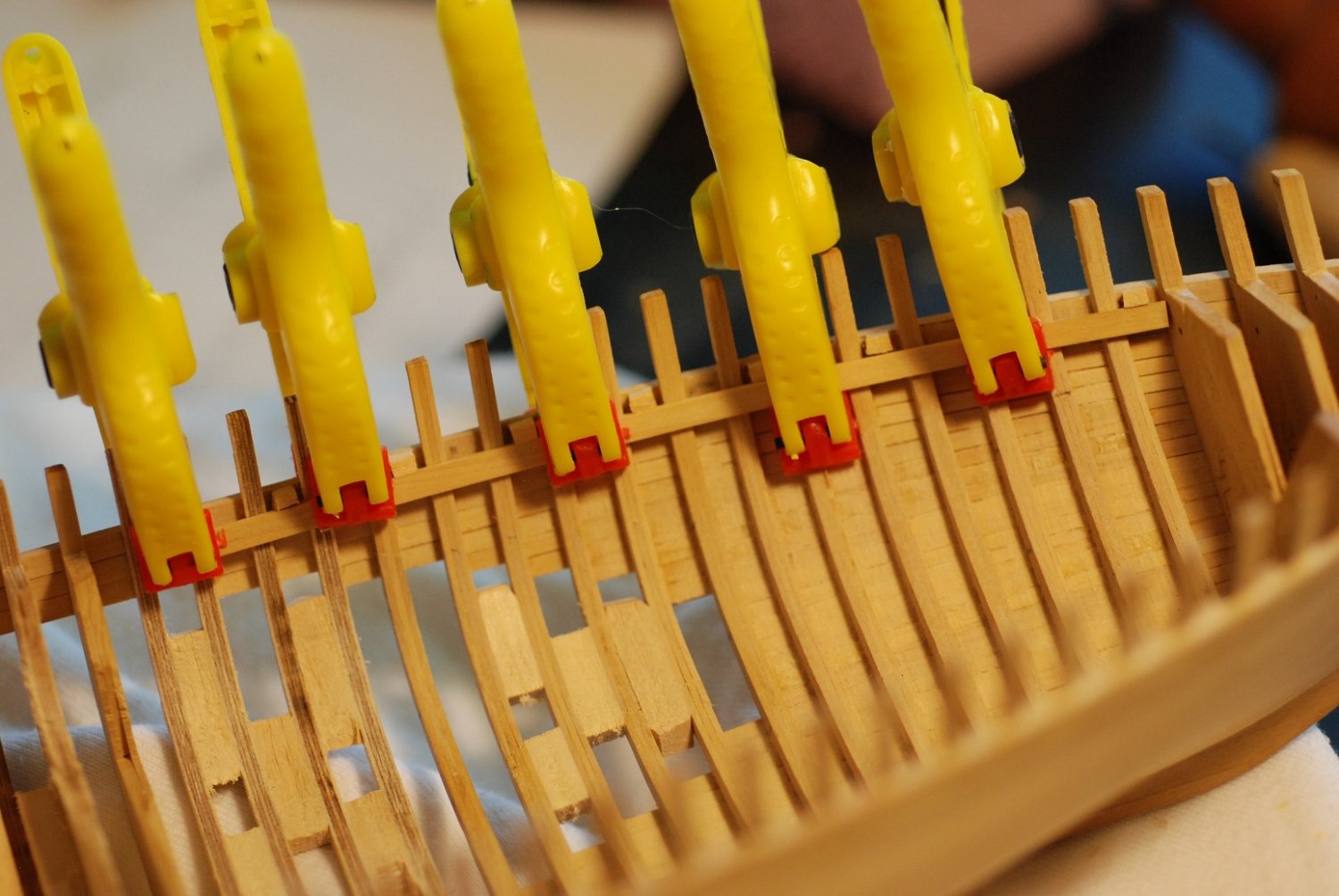
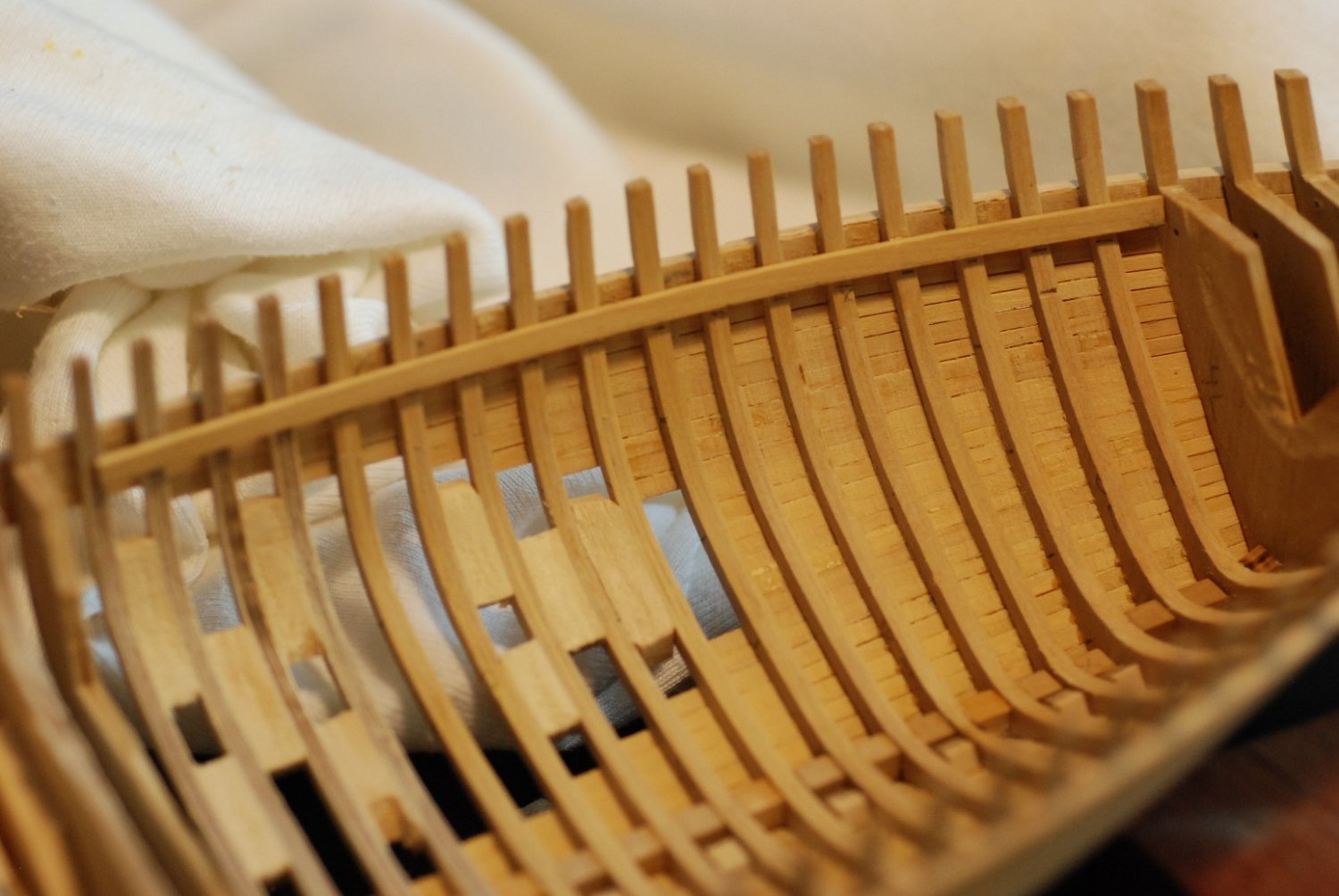
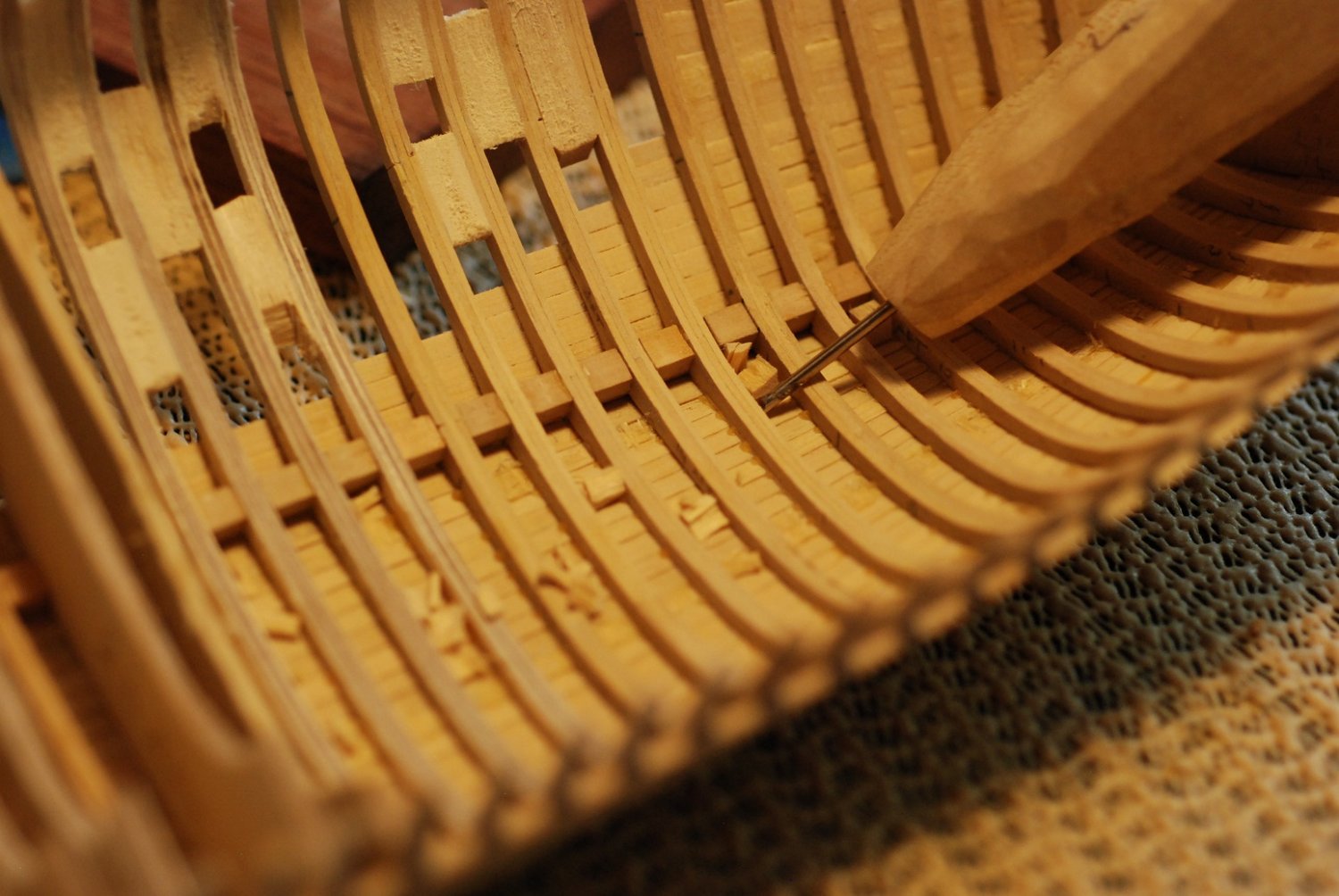
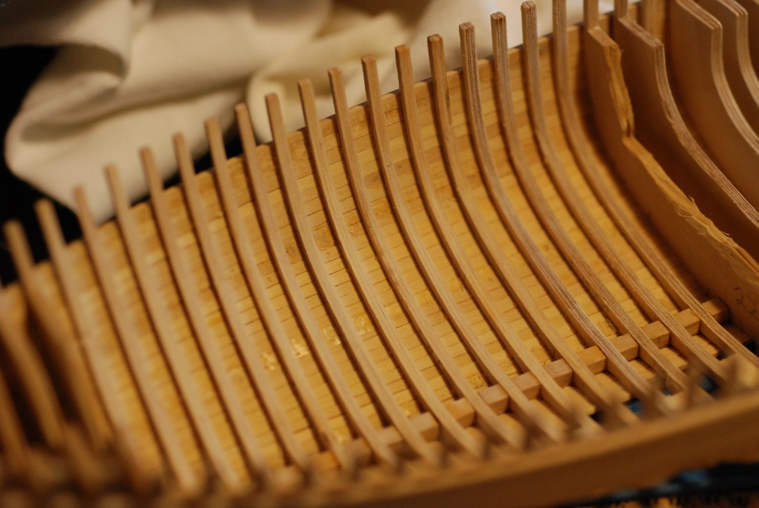
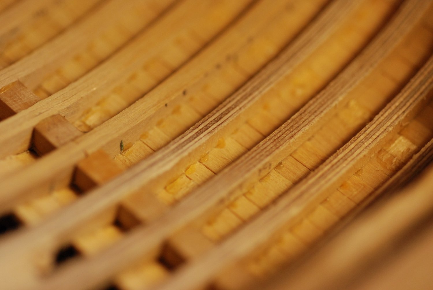
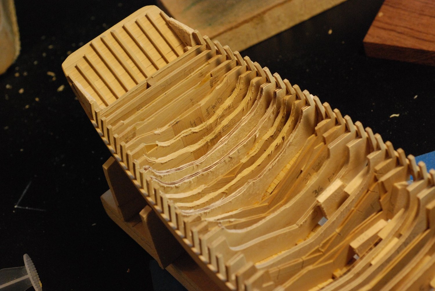
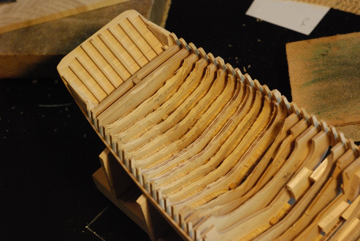
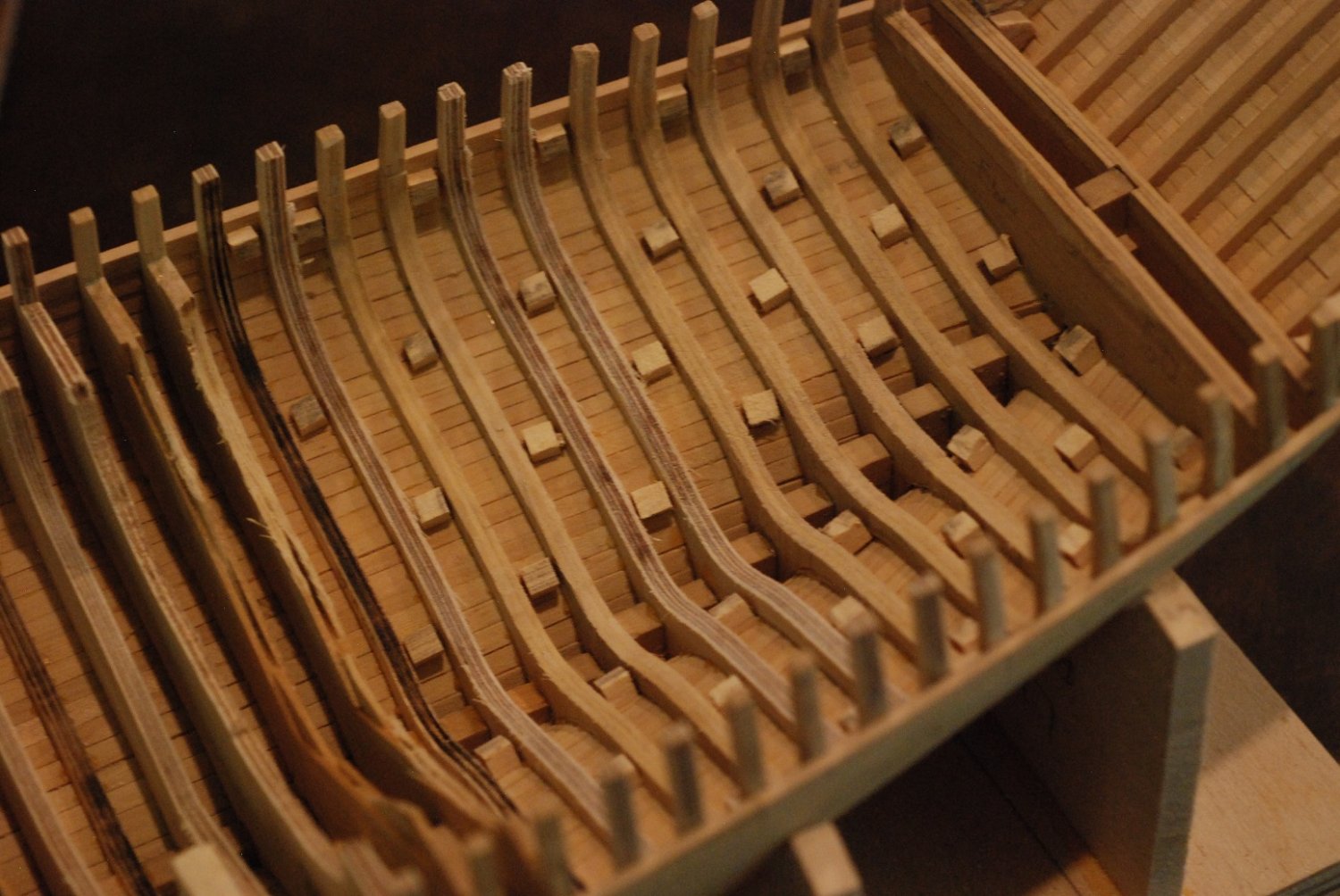
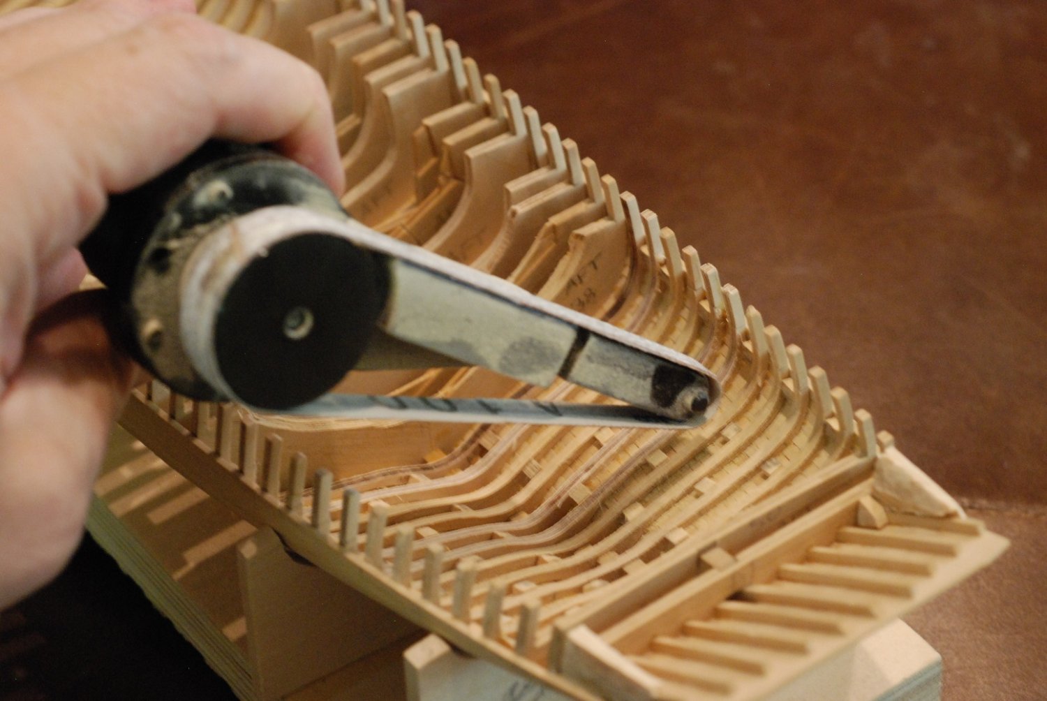
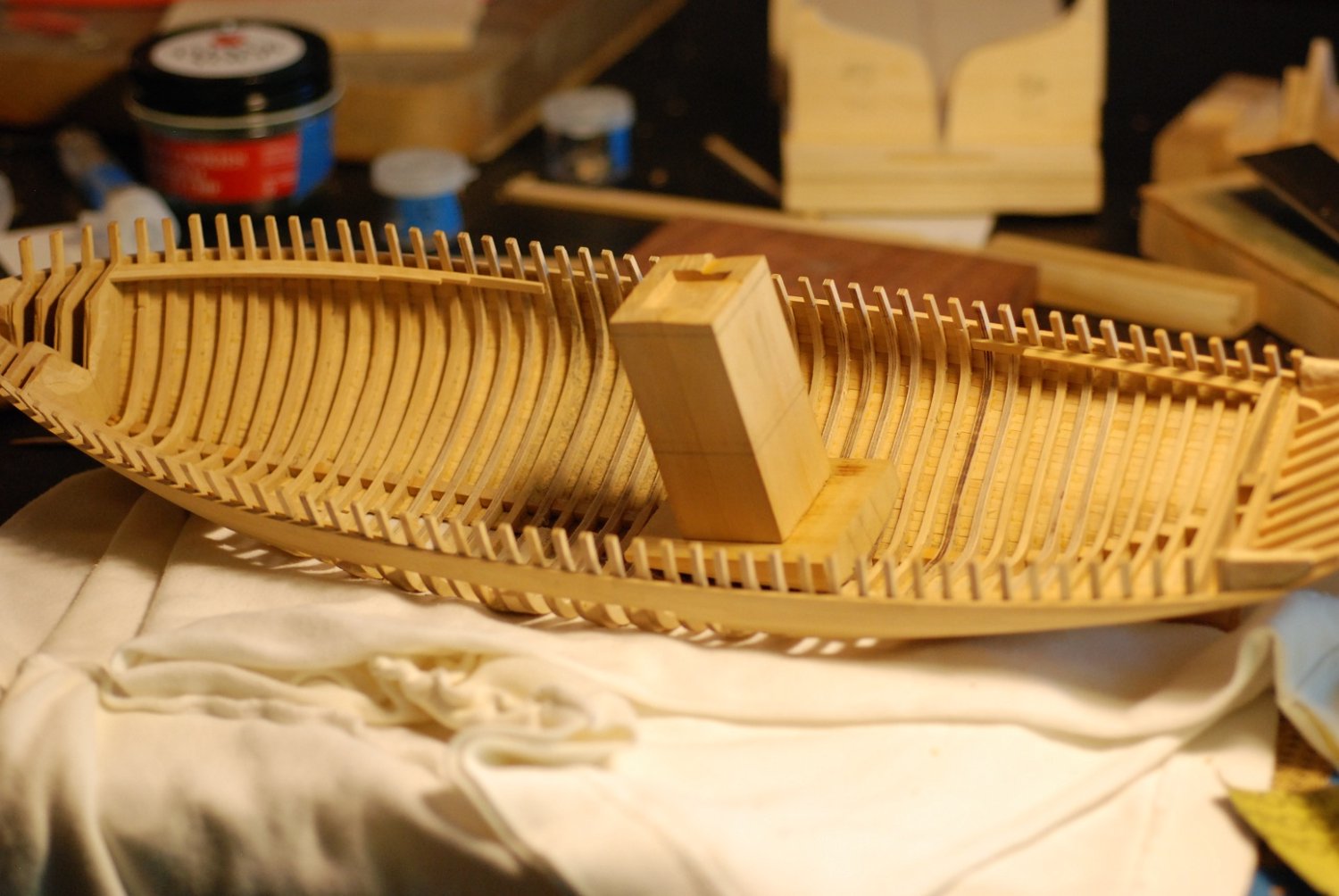
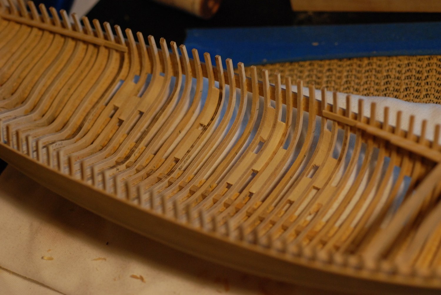
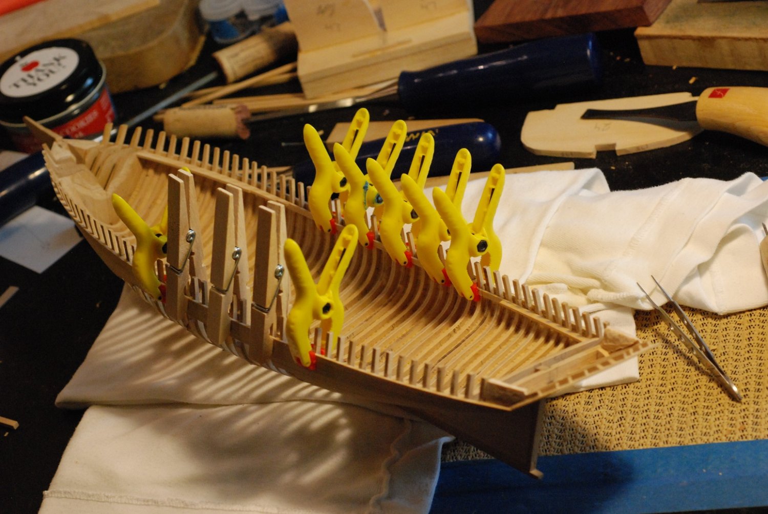
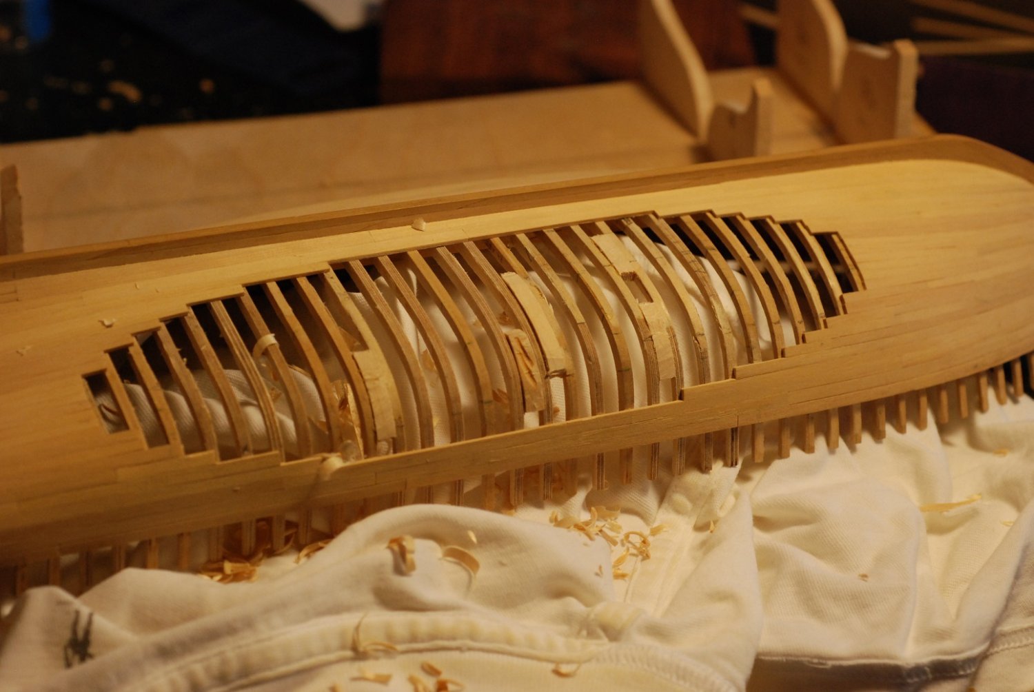
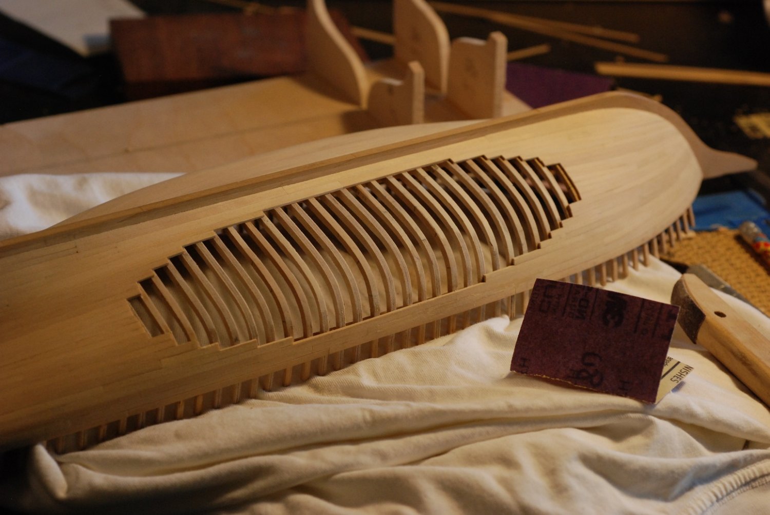
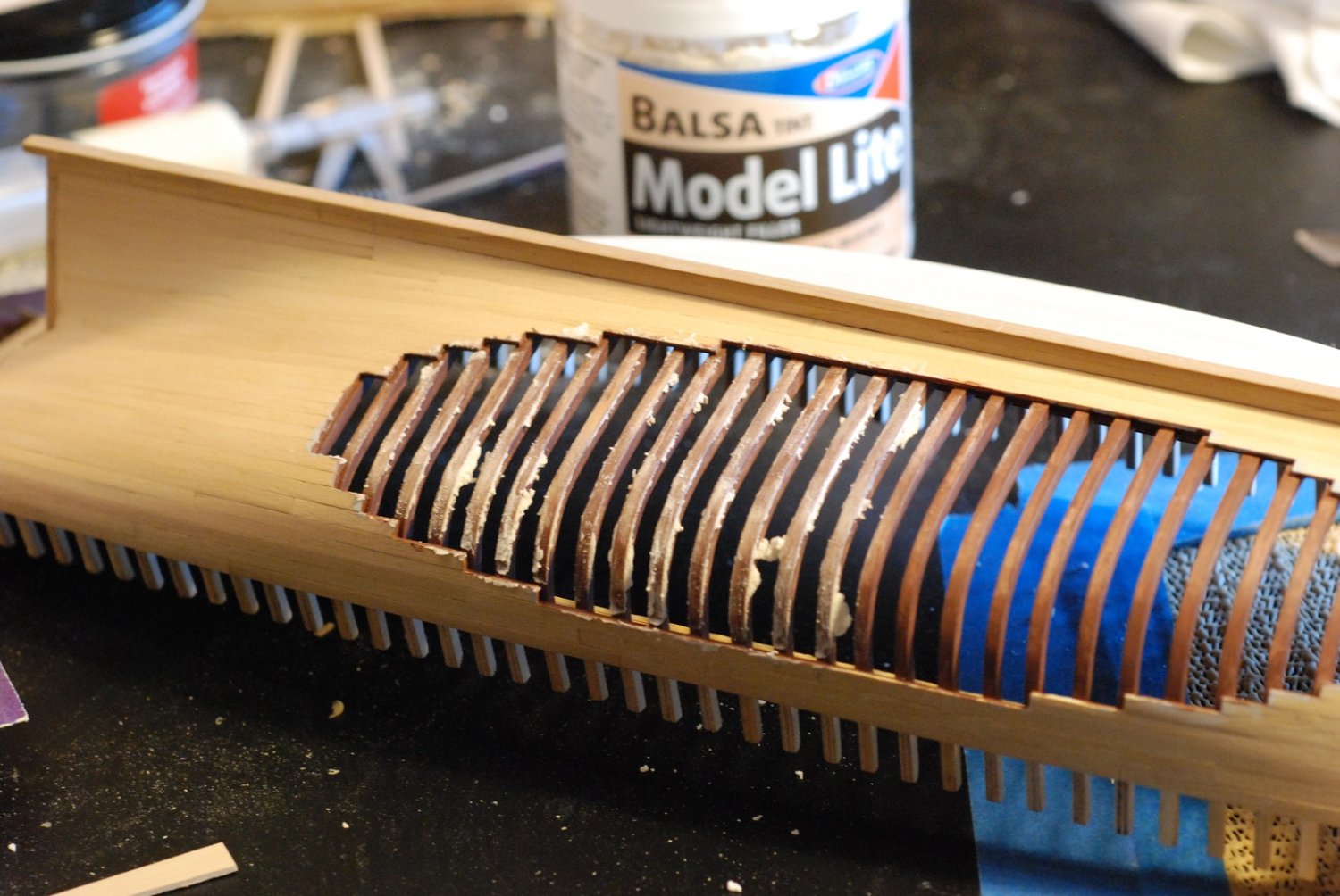
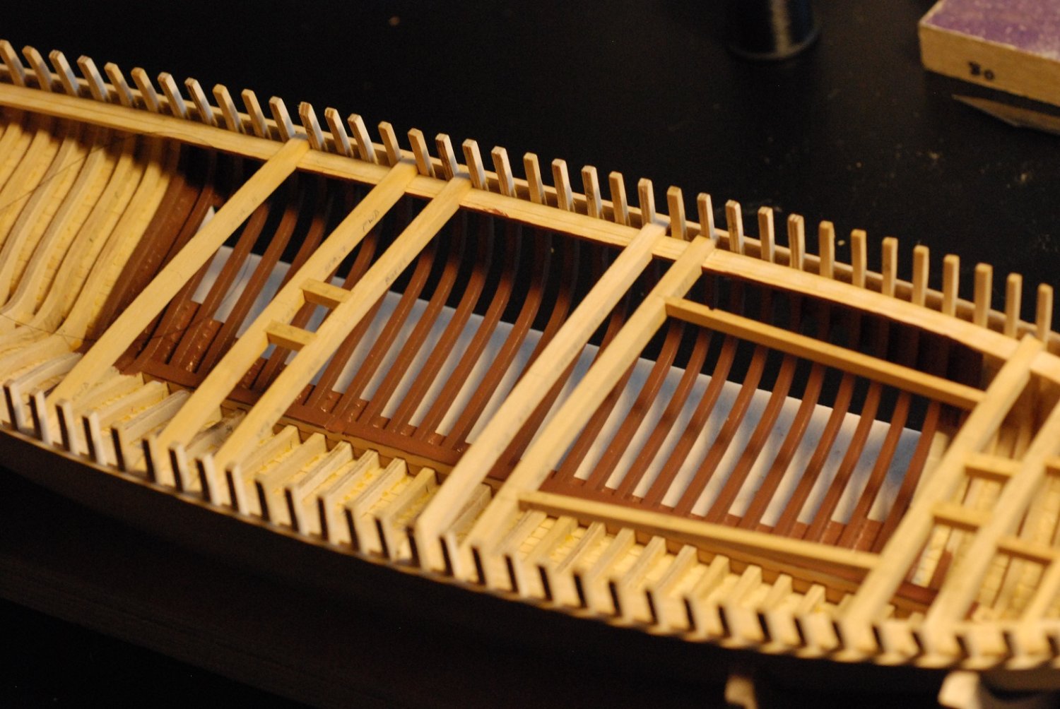
Wow, it's been 6 months since my last post! This next post is sort of a moment of truth. It’s time to grind out these numerous bulkheads down to forms that resemble the actual shapes of the interior framing of the boat. Which is no small task given the volume and number of these bulkheads. Numerous tools were considered for the job. The work in the above picture was done with the drum sander attachment to a Dremel. Here are some hand tools I tried, in an effort to see how safely and efficiently wood could be removed. But it was pretty clear that the job called for more than just a Dremel. It was time to invest in a Foredom rotary tool. The Foredom is essentially the same kind of tool as a Dremel with a flex-shaft, but there are an amazing number of handpieces that can be attached to a Foredom. So I set up the workbench outside, with a hanging stand for the motor and a bullnose bit attached to the handpiece. This tool works very well and generates huge amounts of sawdust. It makes quick work of grinding down the frames, but I had to make a deal with myself to only go so far with this tool. It could very easily do serious damage if I lost control of it. In the bow, there are four frames just aft of the bow filler blocks that I will not grind down. As a reminder, certain of the frames had been previously brought down to their proper molded dimensions, to serve as guides for future fairing of the frames between them. Three of these frames are visible here. As I got closer and closer to proper molded dimensions, I decided to temporarily glue sacrificial blocks that were of the target thickness of the frames in those areas. I could mark these with pencil and watch to see when I was starting to hit their surface in order to get an idea of when I was getting close. Sort of like topography lines on a topo map, the blocks are lined up on the points at which each frame should have a certain molded dimension. It was a lot of work bringing the frames down to their proper dimensions. Here I am using sandpaper to take off the really coarse marks left behind by the bullnose bit. This was how I handled the forward third of the hull. In the middle third, I kept the bulkheads in place for the moment, because I wasn’t certain of the stability of the hull. In order to stabilize the ground-out bow segment, I moved on to installation of the deck clamps. In this picture, the measuring blocks for the molded dimensions of the frames at the level of the sheerline have been removed. In their place, new blocks have been installed that properly space the deck clamps from the sheerline. Using these blocks, the initial stringer of the deck clamps was installed. (I guess this particular piece would be called the deck clamp, and then additional pieces inboard of it would be the beam shelf.) These spacer blocks were then removed. Here the thickness guide blocks are being removed from the areas where proper thickness has been achieved. That is a very satisfying look. If you look closer, though, you can see the difference between the frames that were made from sandwiched layers of Castello boxwood and those made with Baltic birch plywood. Also visible are beads of squeezed-out glue from planking installation. Now I moved on to the stern third. The two aftmost bulkheads will stay in place. Once again, the bullnose bit was used initially. And then thickness guides were installed. I really needed a faster way to bring the frames down to proper thickness, without the violence of the bullnose bit. I had seen this device used by other builders on their build logs, and it appeared to be ideal for getting into small areas better than any other attachment. It requires a different handpiece attachment to the Foredom (a right angle attachment) and is a bit of an investment, but the same handpiece can be used for other useful things like an angle grinder. After smoothing the frames, the deck clamp was installed. Then on to the midships portion of the hull, with the same technique. Here I am using a hand held thingie to which I could apply adhesive-backed 60 grit sandpaper for fairing of the interior surfaces of the midships frames. These support blocks did their job of supporting the free-floating frames in the unplanked portion of the hull. The midships portions of the deck clamps are being installed. Then the keelson was manufactured in 3 parts. It was carried to just short of the deadwood. The keelson installed. Deck clamps and beam shelves fully installed. Time to remove the support pieces of wood between the frames. In addition to the unplanked frames, a portion of the deck in this same area will be omitted to show the deck beams, carlings, and ledges. Primer has been applied to the exposed frames. I applied some paint just to see how it would look, and the appearance indicated that smoothing with filler would be necessary. Doing this helped to make the frames look the same as one another, whether they were sandwiched boxwood or birch plywood. This was after 2-3 coats of brown paint. Since the deck will be partially unplanked, I also applied the paint to the portion of the interior that would be visible through an unplanked portion of decking. This picture gives a preview of some of the deck beams and carlings. This process will be covered in the next post.


-
You bet! Rob Napier once referred to its bow as having the "Mother of all figureheads"! If anyone can duplicate this, it would be Johann!
.thumb.jpg.bb2215a5690a490088b093e4dfdf8533.jpg)
.thumb.jpg.60d39a21b60329db3d7b649d2120cde7.jpg)
.thumb.jpg.625c84802a8b24cf3348d37df3252667.jpg)
-
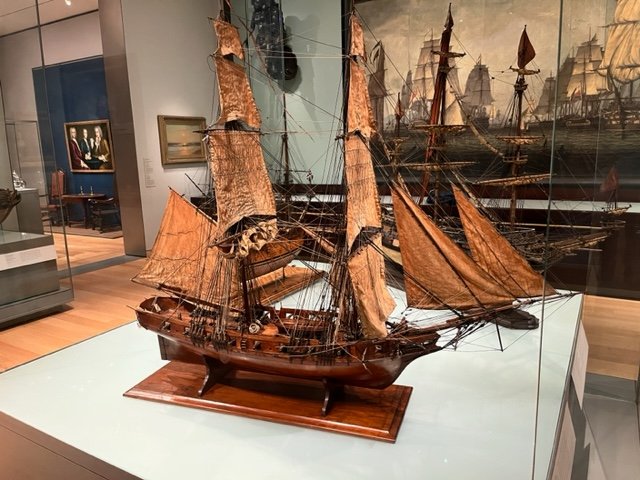
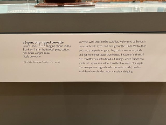
Johann, maybe you know about this model already, but I will send you these pictures anyway. I was just at the Museum of Fine Arts in Boston, Massachusetts, USA. They have a small but important collection of ship models, and one of them is this French corvette from around 1810. I instantly thought of your build log. I hope you enjoy the pictures!

-
The final finish on the spars is very impressive too. Was that achieved simply with sanding? How fine a grit sandpaper did you finish with?
-
Merci Gerard, that helps a great deal.
-
I am scratching my head over M. Delacroix's comment that the "front surface of the yard is at the top of the picture". Does that mean that the attached stuns'l boom is located forward of the yard? I thought it would rest on the top surface of the yard.
-
Looks like a repurposed massage therapy bed!
-
ancre Le François 1683 by jose_b - Scale 1:48
jdbondy replied to jose_b's topic in - Build logs for subjects built 1501 - 1750
Jose, glad to see you are back up and running. I am working on cutting out parts for the frames for Le Francois, while also working on my Maine coastal schooner. I will take a look back at your previous posts for some inspiration! -
Jerome, I have not tried gold leaf. I think for this tiny scale I am doing ok with paint.
-
Keith, I think it's a combination of the magnification of the image and the relative coarseness of the sanding job at that particular time. Here is a more recent photo showing the same area after more sanding (but not finished yet). The planking is Castello boxwood.
-
Hmm. It seems my pictures attached to that last post somewhat out of order. Which means I didn't explain an image toward the end. The last picture shows support blocks I have temporarily glued in between the bulwarks, which will next be ground down to frames. I didn't want to be violently grinding them down without some fore-and-aft support. Thanks to Greg for the suggestion of how to do this most easily. The support blocks came from the jig I used earlier in the process. I was able to individually select pieces of appropriate thickness to fit each of the gaps between frames. Once internal fairing is done, these blocks will come out and the faces of the frames will be cleaned up. They will end up being painted, as will the rest of the hull.
-
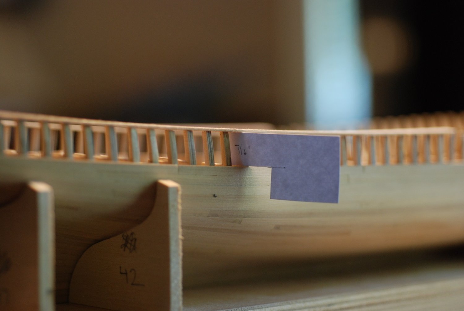
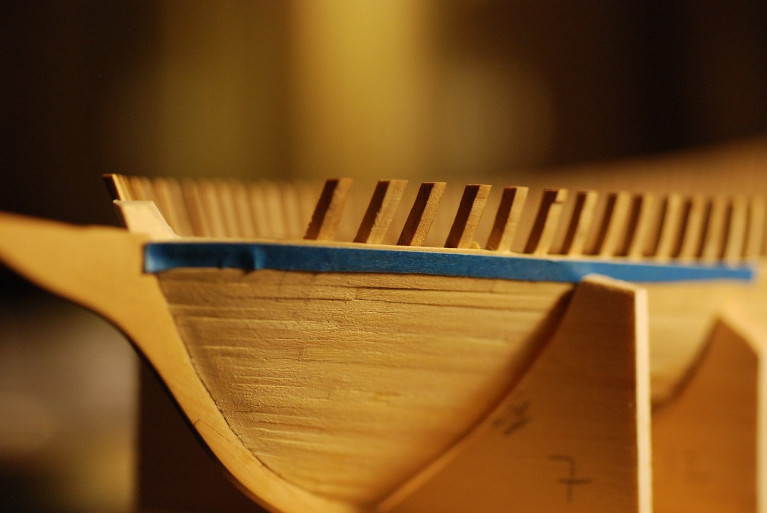
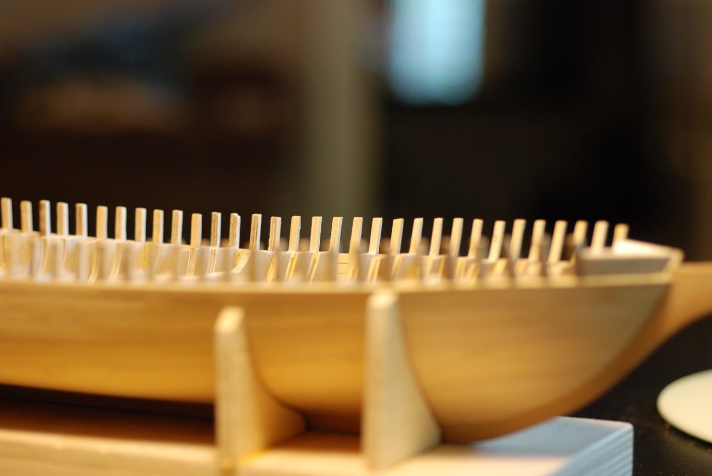
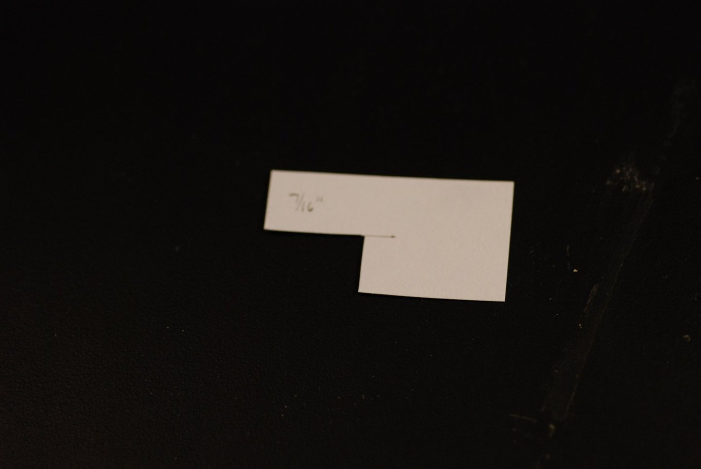
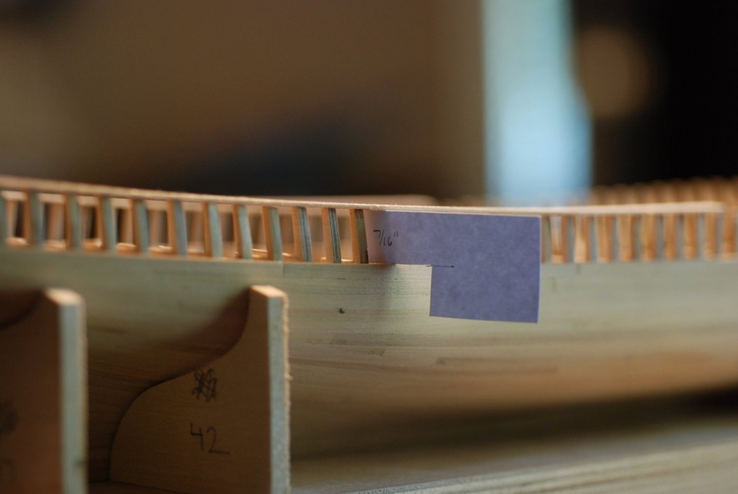
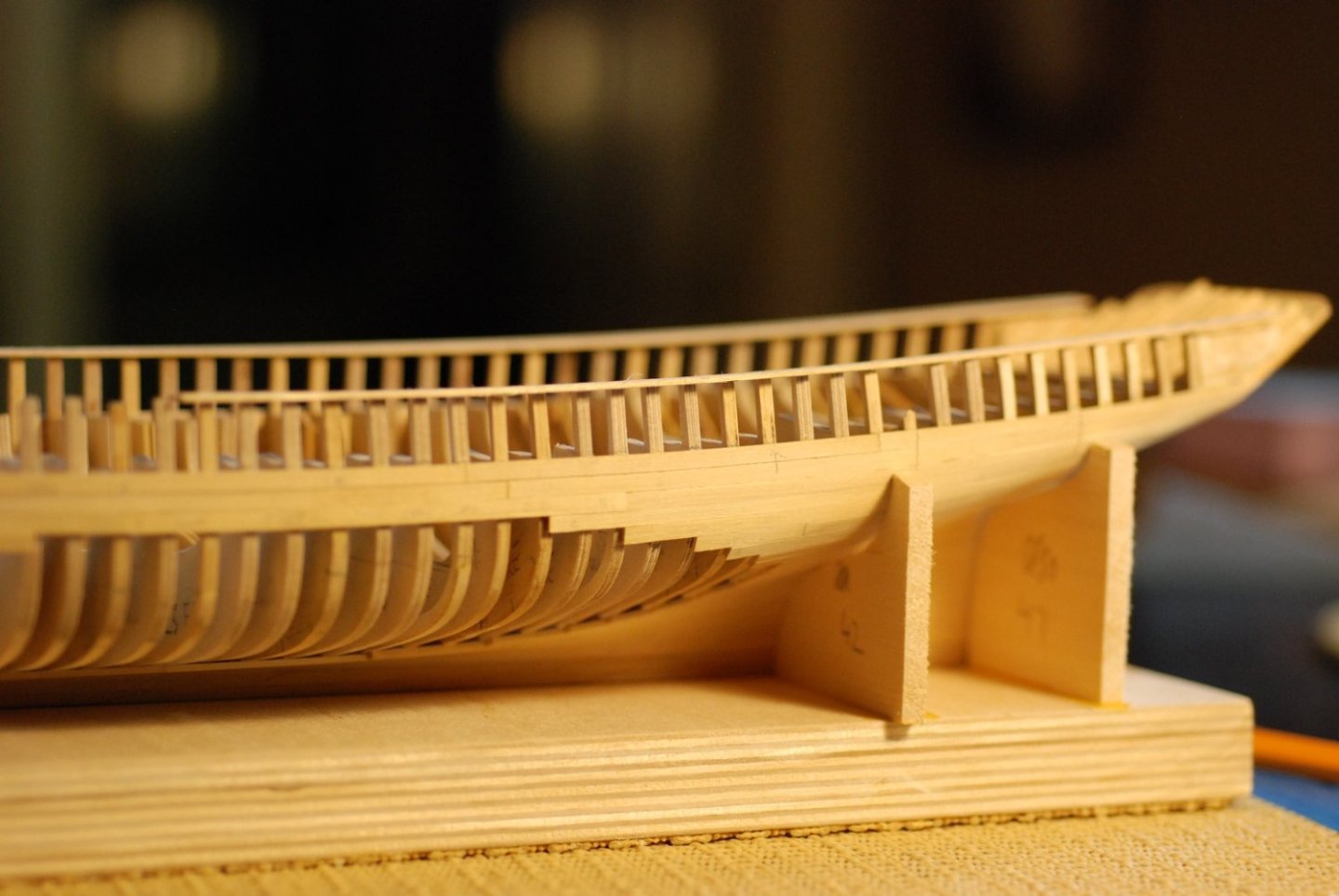
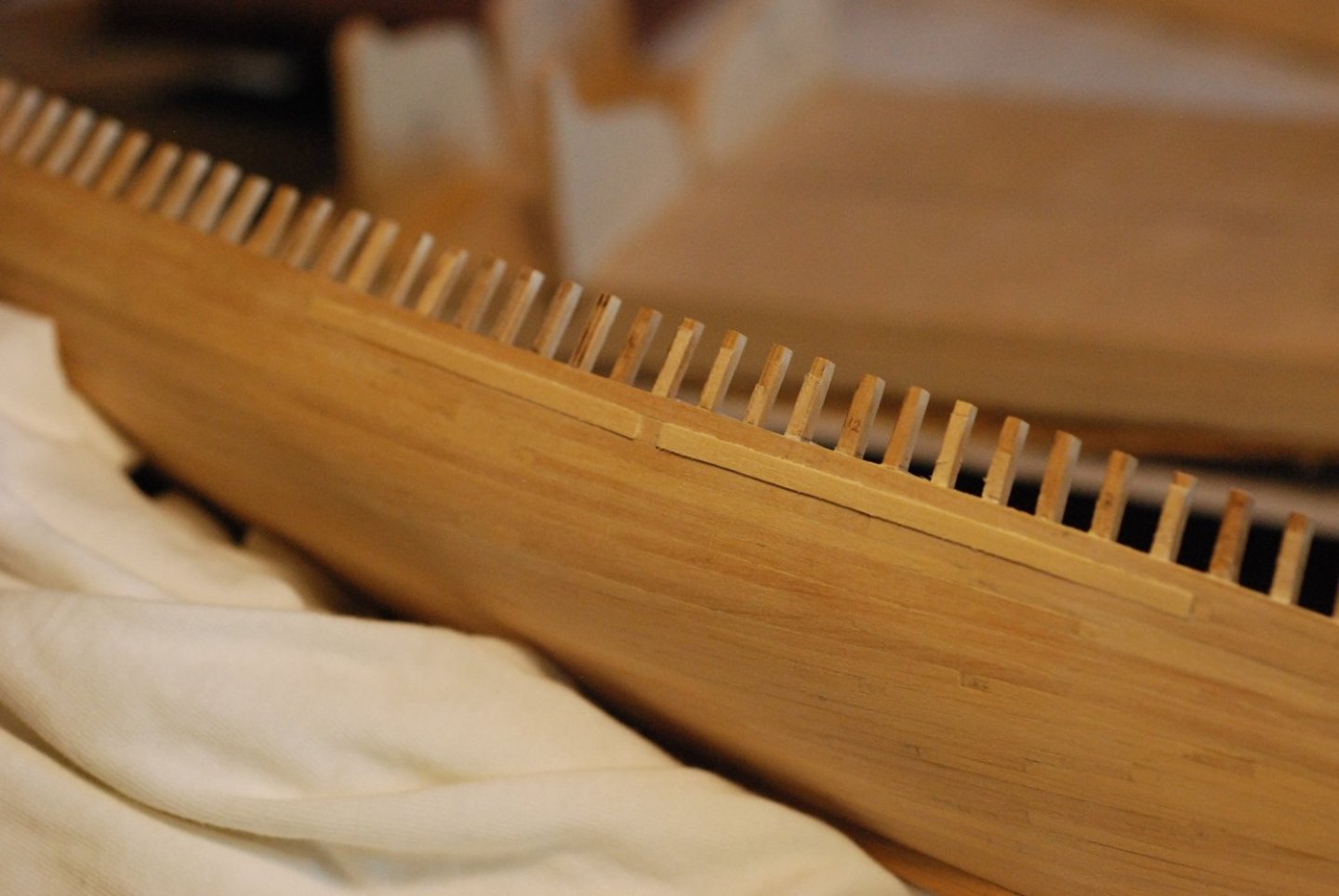
It's time to clean up the hull in various ways before moving on to the interior of the hull. First I built a stand for the hull to rest upright, conveniently aided by cut-outs of four of the station shapes. "Non-skid" was applied to the bottom, consisting of a piece of carpet pad. This image of the bow shows two things to be addressed: First, pencil marks on the hull indicate low spots in the planking that require filling prior to fairing. Second, the topmost sheer strake is fastened to the hull so that its top edge will not be fair with anything. If I were to lay down a covering board on the top edge of this plank, there would be a big gap due to the angle between the sheer plank and the covering board. Also, at the stem, the top sheer plank dives down in an unacceptable manner. This area needs to be filled. In addition to the fairing of the planking, I have to stabilize the exposed frames before I go grinding out their interior surfaces and give them the actual shape of exposed frames. Then, the tops of the stanchions are not regular at all; they were purposefully made a little long so that they could be faired down. I made a feeler gauge out of cardstock, with the necessary 7/16" height for the bulwarks planking. A strip was applied to the tops of the stanchions as they were faired down to the correct height. Just ensuring that everything is nice and level. Here I am applying a much larger than necessary strip of wood that will fill the gap at the top of the sheer planking at the bow. Tape was then applied in order to indicate the proper sheer line. I then used a blade and a file to bring down the thickness of the plank between the stanchions, then carefully cut down the wood next to the stanchions before sanding it into a smooth sheer line. If left uncorrected, the gap at the stem would have been very large. I don't have many pictures documenting the fairing process. But this picture shows a strip of appropriate width filling a low spot at the level of the sheer planking. The Mary Day does not have a clear step-off between the sheer planking and the planking of the rest of the hull. When originally built, there was a clear transition between the hull planking and the sheerstrakes, but the builder (and his sons I am told) didn't like the way it looked. So they later planed out the step-off, so there is a smooth transition between the hull planking and the sheer planking. Next episode I will report on my progress on the interior work.


-
Landlubber Mike's technique for furled sails
jdbondy replied to Landlubber Mike's topic in Masting, rigging and sails
I also agree that putting on sails when the yards are already attached would be extremely difficult. On my most recent completed build, the headsails were attached to the already installed bowsprit but only standing rigging had already been installed and nothing else. The rest of the sails were attached to their various spars prior to installation. -
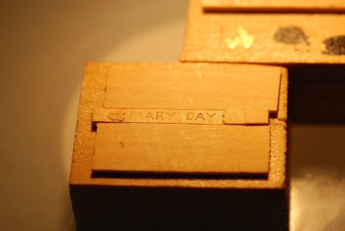
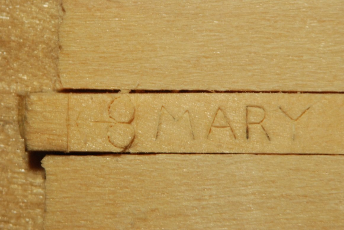
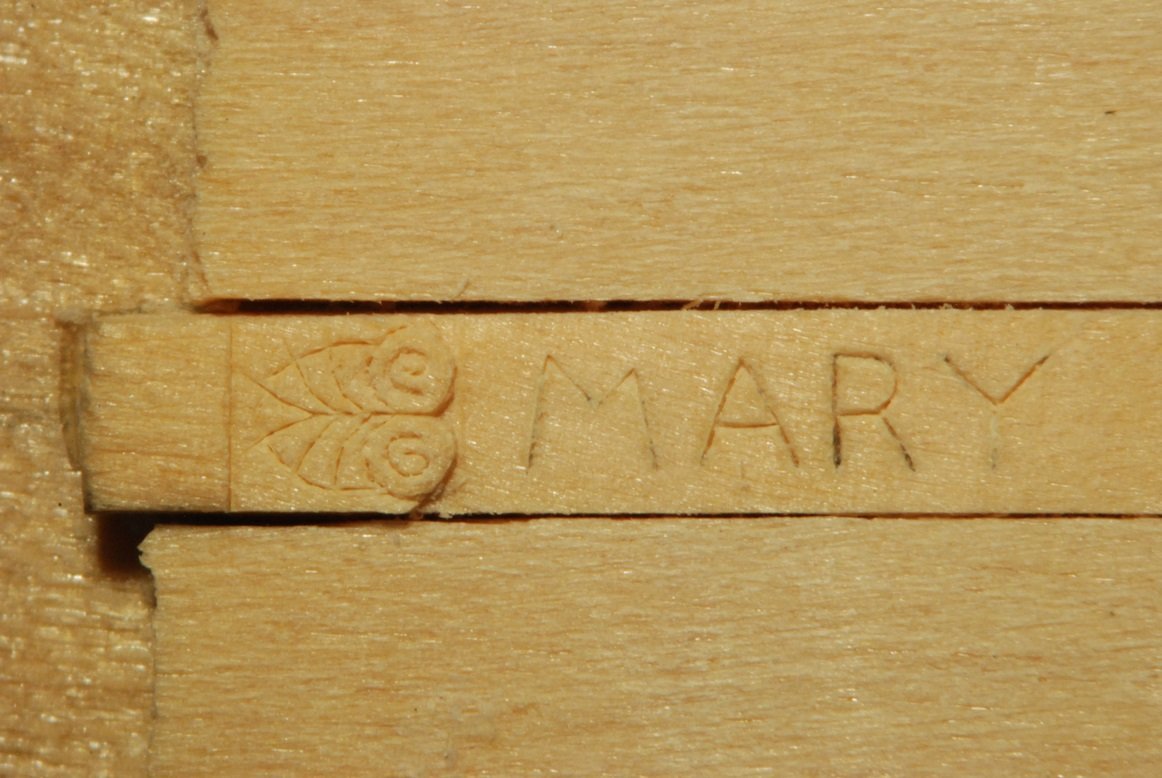
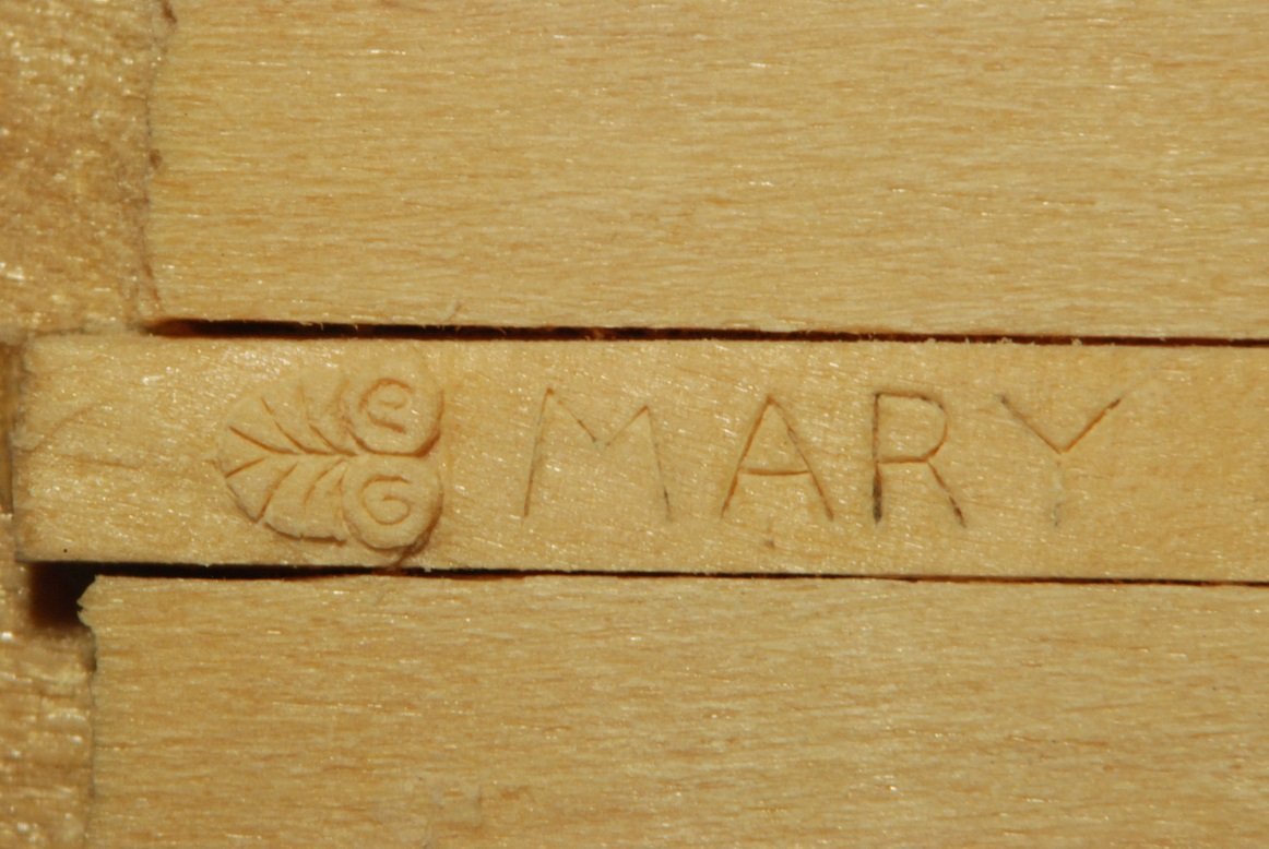
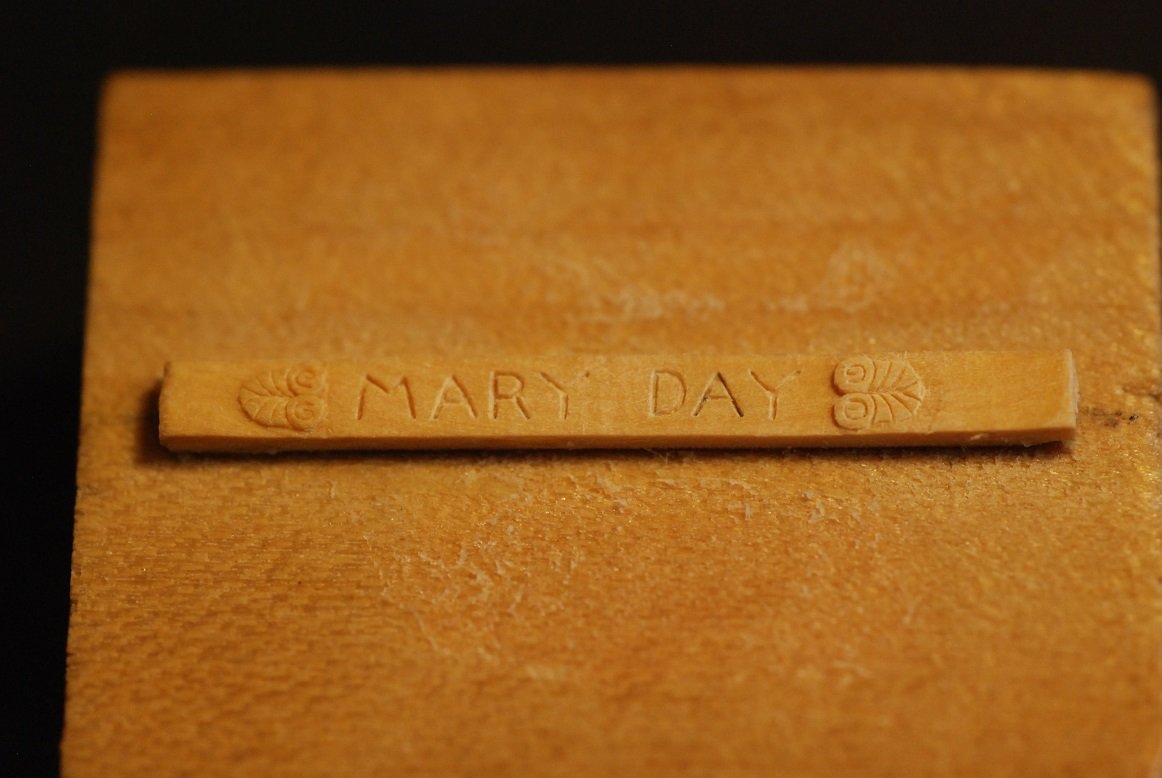
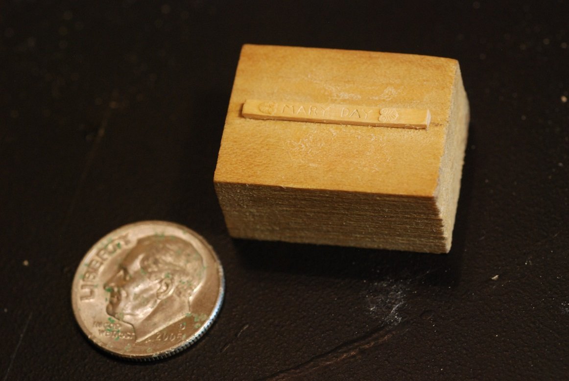
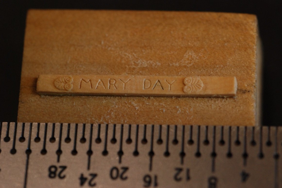
I am working on a side project for the Mary Day, dedicated to carving her nameplate in miniature. At 3/16" scale, this nameboard comes out to just under 1 inch in length. So this is going to call for the microscope, as well as some specialized carving tools. My starting tool is the #11 scalpel blade, and from there, I made very fine tools using the smallest Japanese sewing needles I could find. These were ground down using a diamond stone. From left to right, there is a "blunt tip" tool, then a "coarse" (ha ha) chisel, then a fine chisel, then a sharp point tool. These images were taken under the microscope, focusing on the fancy detail at the edge of the nameboard. It's simply not possible to capture an image of me actually working on the piece, as one of the eyepieces has to be replaced by the camera insert. In general, I make tiny stop cuts in the wood using the chisel, then I force the cut open with one of the needle tip tools. Probing around with the tips of those tools frees up tiny bits of wood that are then cleared from the cuts. The cuts gradually become deep enough and wide enough that their detail becomes more visible. End result. A dime for scale purposes. As I said, the overall piece is less than 1 inch long, and perhaps 3/32" in height. Next is to figure out what paint will work well to fill the letters. So far I have tried a popular water-based acrylic, but it seems too "goopy" so far. I have another brand of acrylic I can try. I do also have my ageing stash of Floquil oil based paints, but I don't know if any still remain in liquid form. I am open to suggestions on the choice of paint.

-
You are truly a nautical polyglot! Very interesting navigating the terminology in French and German.
-
Halituzun, As they say, Tanıştığımıza memnun oldum! (That's via Google Translate.) Thanks for the nice comments. It's a very satisfying model. I hope to make the blog into the form of an article for publication in our Nautical Research Journal! Good luck with your build!
- 60 replies
-
- 1
-

-
- pride of baltimore ii
- Model Shipways
- (and 1 more)
-
I have been working on the Francois in the sense of studying her plans, understanding her framing structure, and doing some proof of concept work on how to build up her frames most efficiently. I also got a batch of English boxwood recently, and I took a class on doing resawing with the bandsaw so I could learn about how to best use the wood. I used it to create futtocks for several frames but have not tried assembling them yet.
-
Thanks Hubac, thanks Keith! HH, Le Francois awaits!!


.jpg.ff7f0e6fe98506a94cb46bdadbd54a86.jpg)
.jpg.366caa9e4f22ad1456f1f4990c73a3ea.jpg)
.jpg.82f5a5fa59bf63263cc2c930d4917440.jpg)