

bobandlucy
-
Posts
495 -
Joined
-
Last visited
Content Type
Profiles
Forums
Gallery
Events
Posts posted by bobandlucy
-
-
-
On 11/21/2020 at 12:16 PM, kurtvd19 said:
Some of the books had some pages not printed at 100%. I am sure this has been corrected for future prints.
Not corrected on my set. . .
-
On 2/7/2021 at 10:57 PM, GGibson said:
Hi Bob - Not sure what John did when painting/staining, but when I was painting my Norwegian Sailing Pram, I wore vinyl gloves when painting the hull and the seats and just held them while painting. I buy the vinyl gloves in boxes of 100 (I use them also for food handling when doing my meat smoking). I am going to stain the display stand tomorrow and will use gloves and wipe the stain on with a cloth, as you suggested. Hope your Dory is progressing well!
Thanks, G!
-
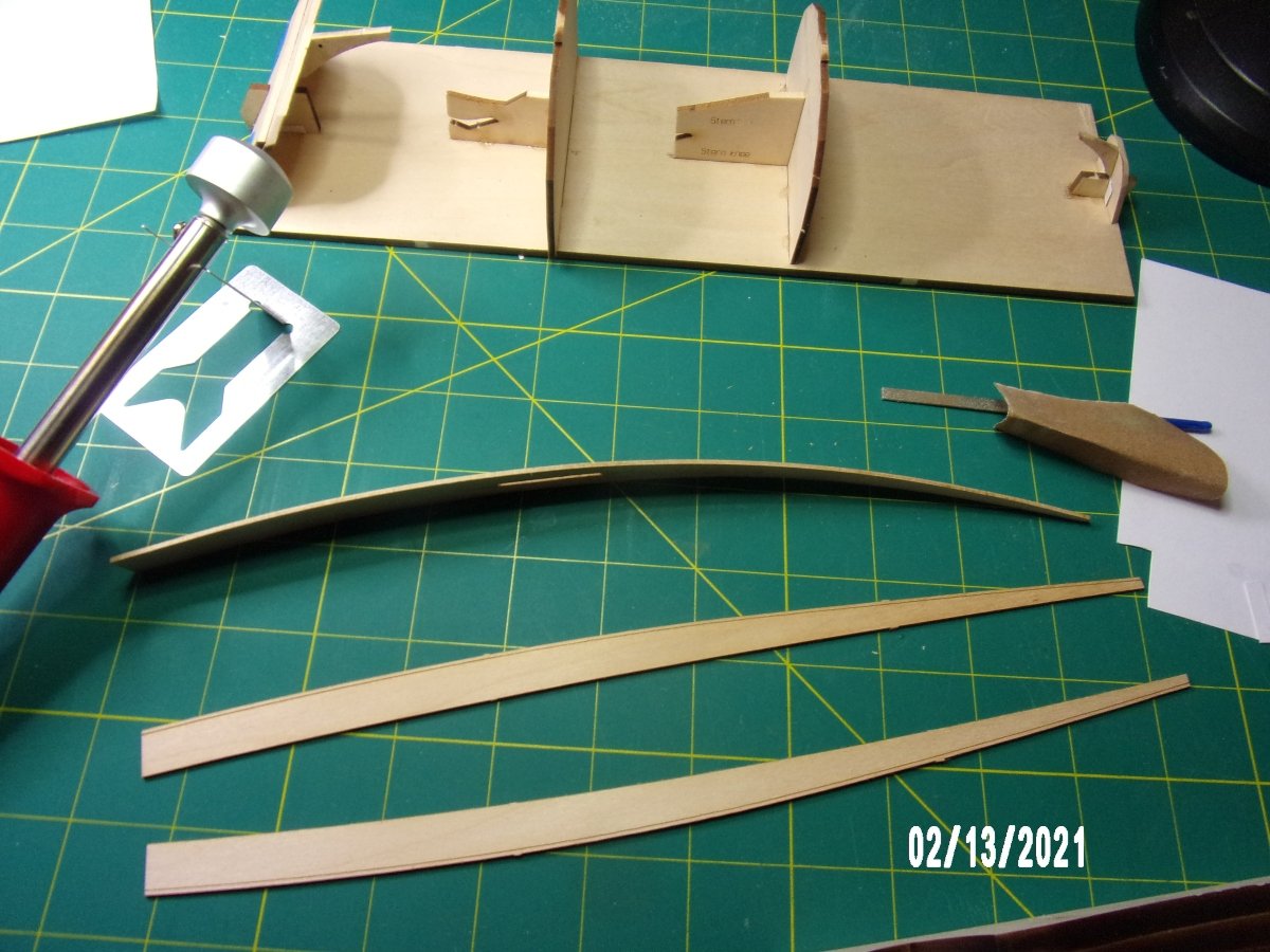
I assembled the building board. It took quite a bit of modification to get the forms to seat, and the transom holders had to be modified with the razor saw, they were way off dimensionally. Since the kit came with an extra keel plank, I decided to try out my electric planking tool. I am very pleased with this method. The grain remains flat and I got a really good fit. It took me a while, but I imagine I'll get faster at it. The plank lies in contact at all 4 points without the need for clamping! The marks visible on the plank are from the char on the form supplied with the planking tool. I'll have to clean that up before I use it again. The marks do sand off easily.
- Bryan Woods, druxey, Ryland Craze and 1 other
-
 4
4
-
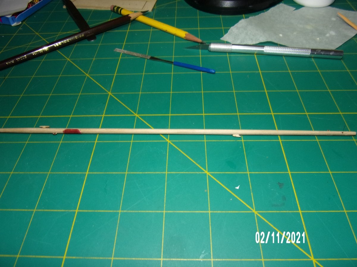
Shaped the mast and added the mast attachments. This assembly will need more work, but I received the part I needed from Model Expo (took less than a week!) and want to get back to the hull assembly and back to doing things in the correct order:
- ubjs and Ryland Craze
-
2
-
I'm not sure at all about the purpose of the sheave, except maybe to help prevent abrasion of the rope when raising the sail? Is so, why does it not appear on both sides of the mast? The rope appears to pass through the sheave once only, so it seems to me that the lower hole did not have to be all the way through the mast. I put mine on the wrong side of the mast, and am debating whether to try and correct with filler.
I also ended up with the "alternative" eye just below the back stay straps, which appears only on the Page 5 plan. I don't think it will have a use. If the eye is indeed an alternative to the sheave, why would it not be shown in the same place as the sheave?
-
-
36 minutes ago, druxey said:
Why bother with a make-shift lathe of any kind? The old time spar-makers simply made the spar a tapered square in cross-section, then planed it octagonal, finally 16-sided and then rounded it off. One can do this easily at model size using a V shaped holder and a 7-10-7 proportioned scale to mark the sides of the square stick out before cutting it octagonal. One can use a mini-plane or sharp chisel for this. It takes little time and, at model size, after the 8-square is cut, sandpaper does the rest of the job. No power equipment required!
This is the method given in the MS Norwegian Sailing Pram kit by David Antscherl. As a matter of fact I am going to shape my mast today. I used the same method on the gaff and boom.
-
Thanks, G
I will be looking to your log when I get back to work on the hull, as you did a great job!
b
-
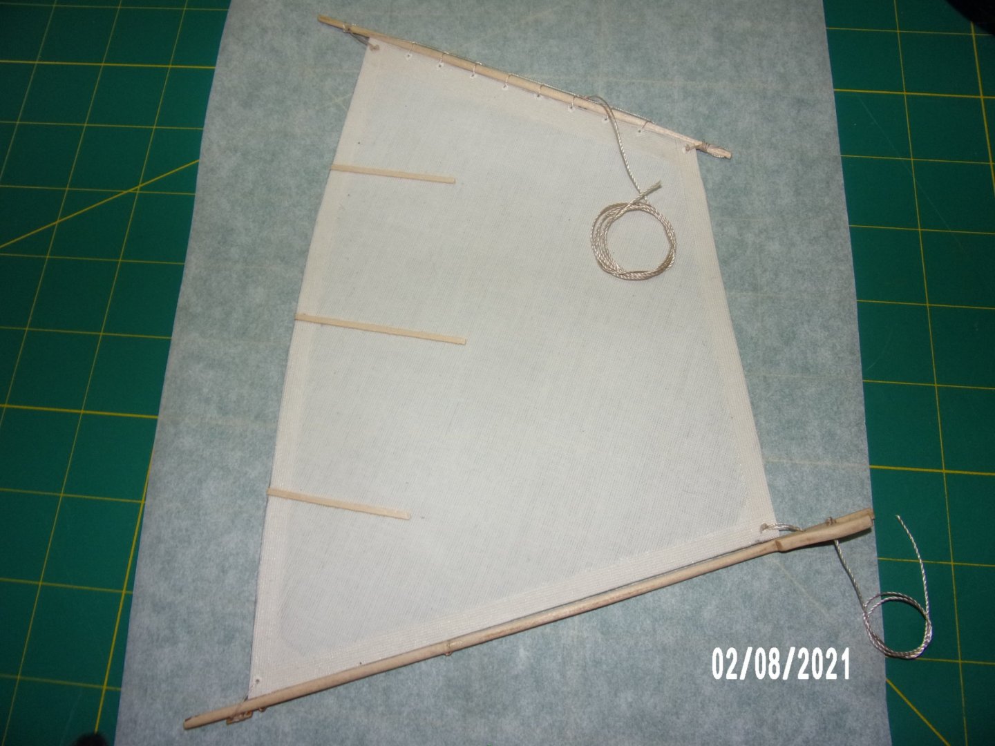
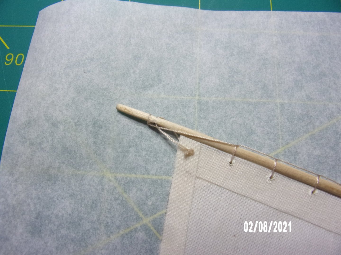
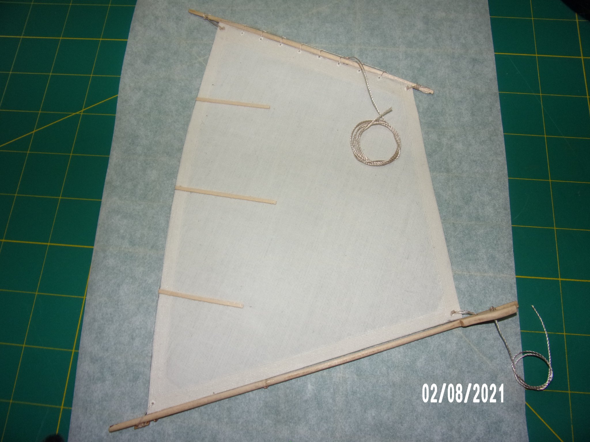
Assembled the sail. I thought I'd never get it right, but am happy with the results. I had broken the boom at the eye towards the center during shaping, and the break is visible, but I can live with that. Definitely going to order a headband magnifier today as the tabletop model I've been using was in the way throughout the lashing/lacing operation.
- Ryland Craze, ccoyle, druxey and 2 others
-
5
-
I'd like to give credit to John and Ed at Model Expo. They have been very responsive in providing the replacement part, listening to feedback, etc. Ed indicated that there is no errata sheet for this model at this time, but he was open to the idea of producing one. This attitude will weigh in my decision to order the lobster smack model next or just plunge into one of the more advanced models which I have.
- druxey and Ryland Craze
-
2
-
My kit also had only 4 supports for the jig. I made the 5th from the leftover sheet stock. Your model looks great!
Bob
-
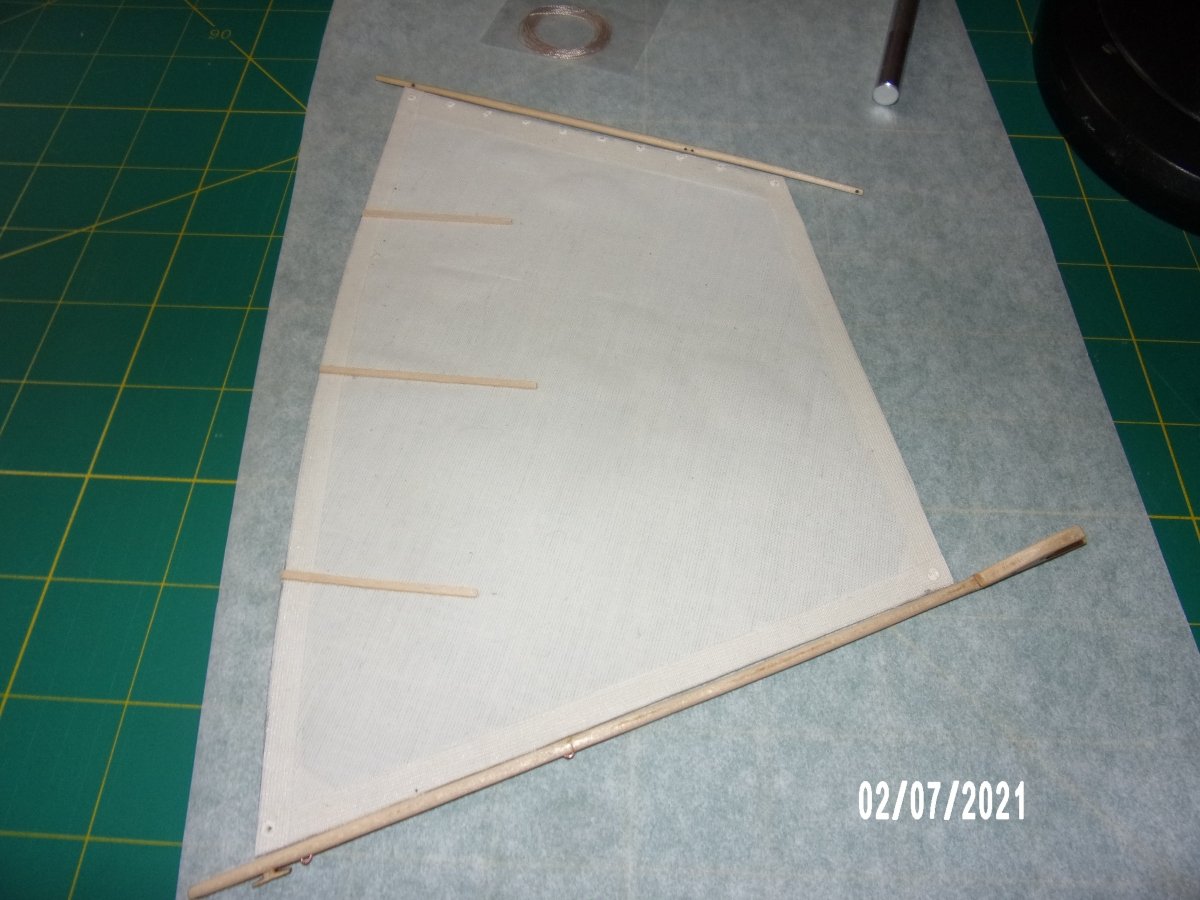
I botched a part and am waiting for it's replacement. Therefore the hull construction is on hold. I decided to build the sail. Another problem arose as I used the sail pattern as supplied assuming it was to scale. It was not, and the sail is somewhat undersized. Looking at another log for this model, I see the same results, and it still looks OK, so I will proceed. The photos show the holes/cleats on the upper and lower spars more or less lining up with the sail corner holes. Since the sail is undersized, the choices are to align one end or the other, and "reach" with the lashing to the hole or cleat on the spar, or split the difference and "reach" on both ends of the sail. I am leaning towards centering the sail.
I am quite happy with the teaching David A. does in this kit. Shaping tips, use of jigs, etc.
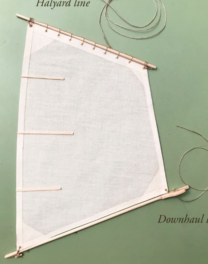
First pic is my sail, second is from the instruction booklet. Apologies for my long-windedness.
- druxey, Ryland Craze and ubjs
-
3
-
I love the details! Very nice model.
Bob
-
Hi, Pete. I've never been to Rohnert Park, but it looks very nice up there, especially on you like wine, beer, and food!
B
-
Thanks, Ryland. I'm learning quite a bit on this model, which is the point. I do wish that the instructions were consistent throughout. But I'm confident that I can overcome these problems. . .
Bob
- druxey and Ryland Craze
-
2
-
-
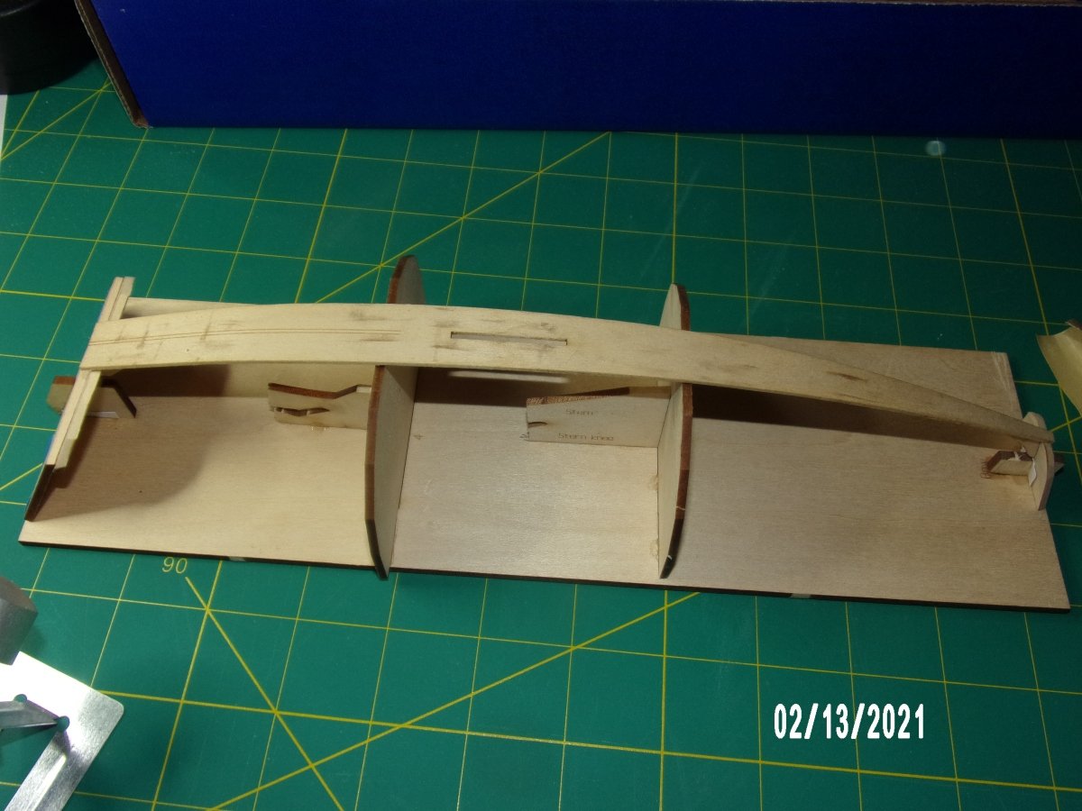
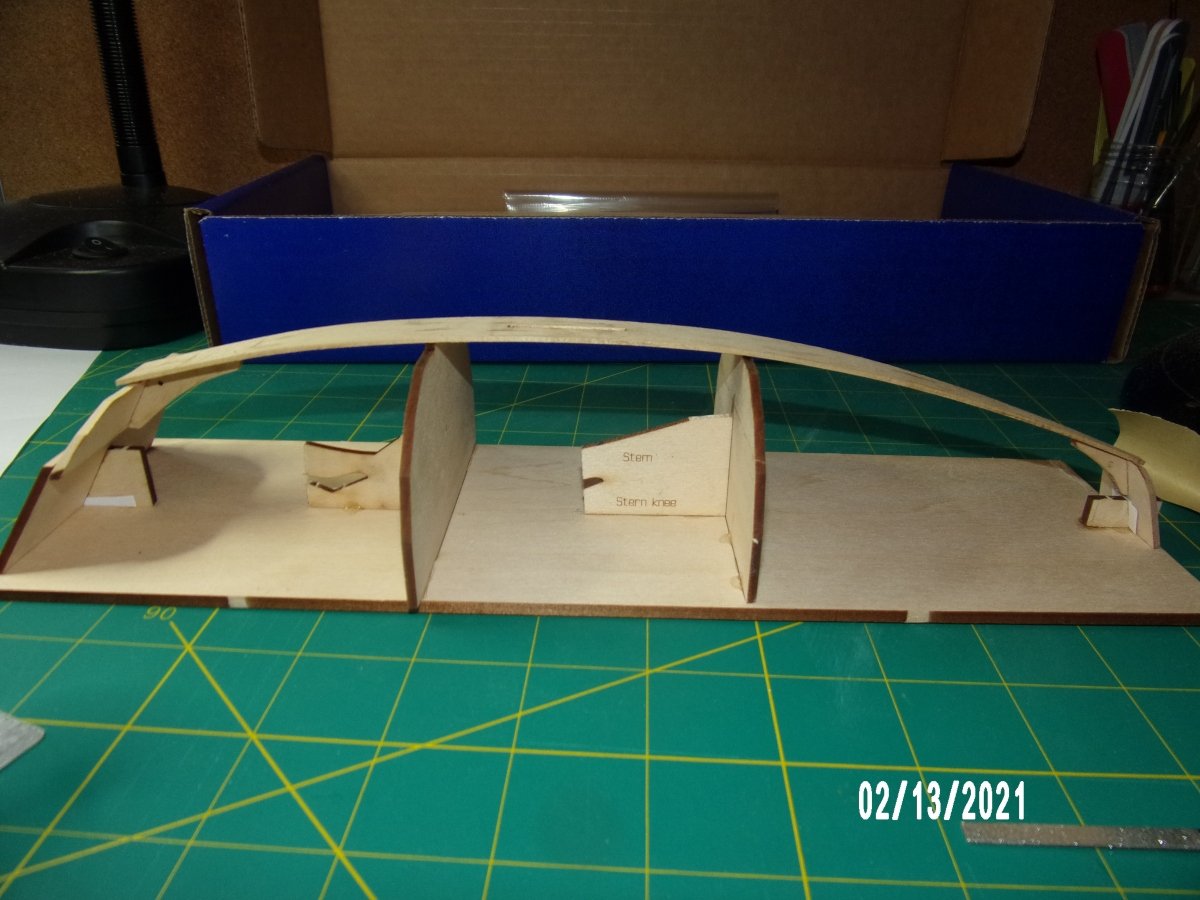
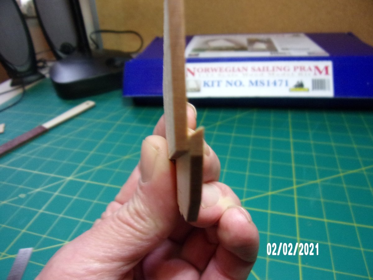
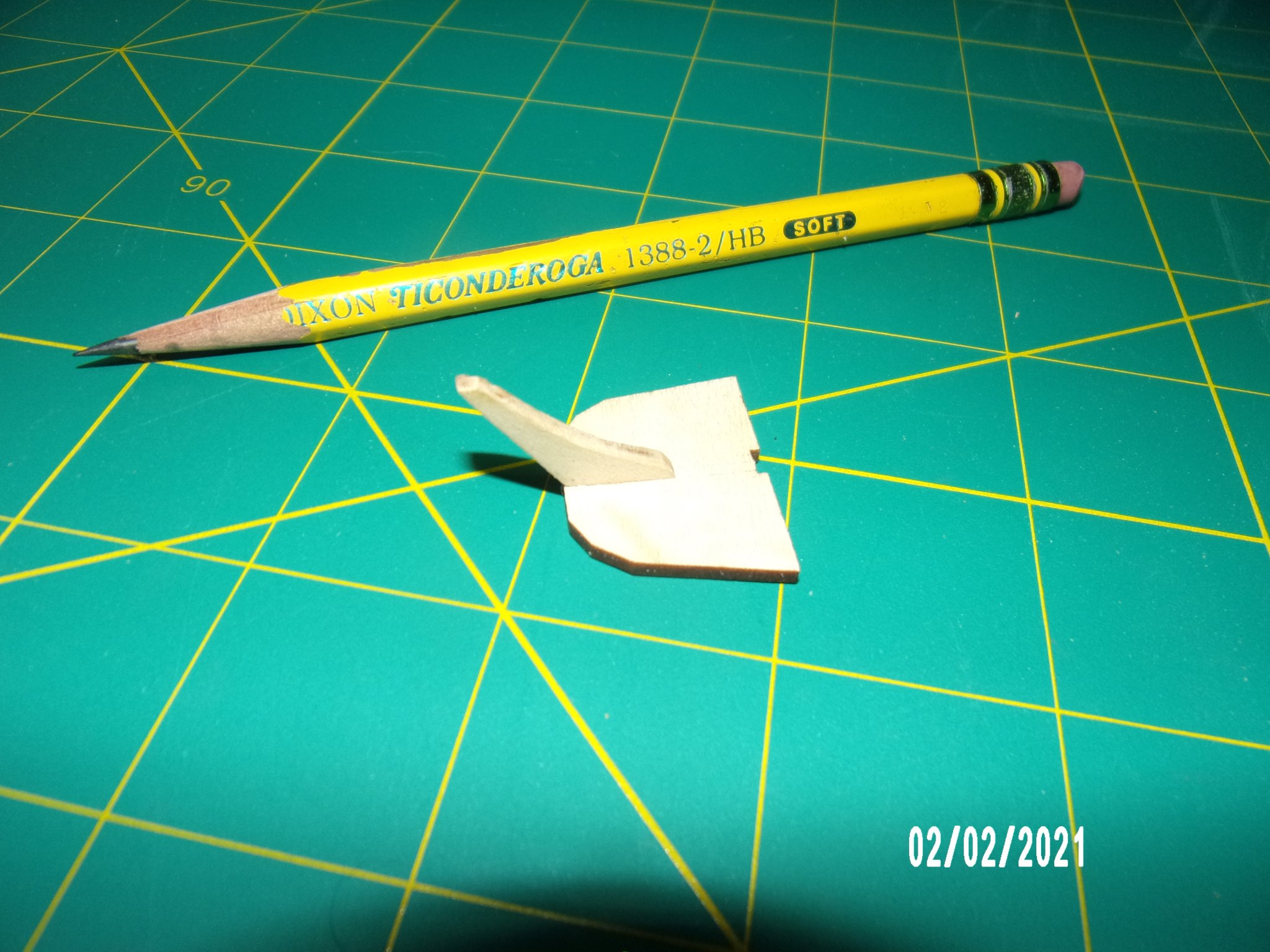
I assembled the bow transom per the instructions. No problem there. When I began on the stern transom - different story. The instructions called for the use of a sanding bevel included with the kit. Cool idea, and one I will remember for the future. The problem arose when the printed instructions read "Turn the [lower] transom so that the bevel marks are facing away from you." If I had my wits about me I would have noticed that the accompanying photo shows the bevel marks facing the camera. I did as the written instructions indicated, because it seemed to jive with the instructions given for beveling the upper stern transom, and after all why would one write such an explicit instruction if wrong? Wrong! (2nd pic below, with pieces held together as they will be glued). As you can see, if assembled this way, it would not result in good joint, and besides would collect and hold water.
I think this will be remedied by transferring the bevel marks on the lower stern transom to the other side, and flipping it.
I noticed that the majority of people logging this build did not do this beveling? Hard to tell from the pictures, and even harder from the pic in the supplied instruction booklet. . .
This hurt my brain cell, but after all this is partly the reason to take up a new hobby- to keep the cell alive and keep it company, since all his buddies have died.
Lessons learned:
1. Understand what I'm doing at all times. If the result can't be envisioned, DO NOT PROCEED.
2. Look at the instructions in PDF format as the pics can be zoomed.
3. Do not be dismayed, as almost everything is fixable.

-
I have begun work on the pram, the second in the progressive learning series by Model Shipways.

-
1 hour ago, Keithbrad80 said:
Very nice work, and congrats on finishing this model!
Bradley
Thank you, Bradley!
-
15 minutes ago, tarbrush said:
good job Bob, that came out real nice!
Thanks much, John!
-
-
7 minutes ago, Moab said:
A beautiful boat!...Moab
Thanks Moab. I really feel a sense of elation at the moment! Ain't perfect, but better than I expected.
b
-

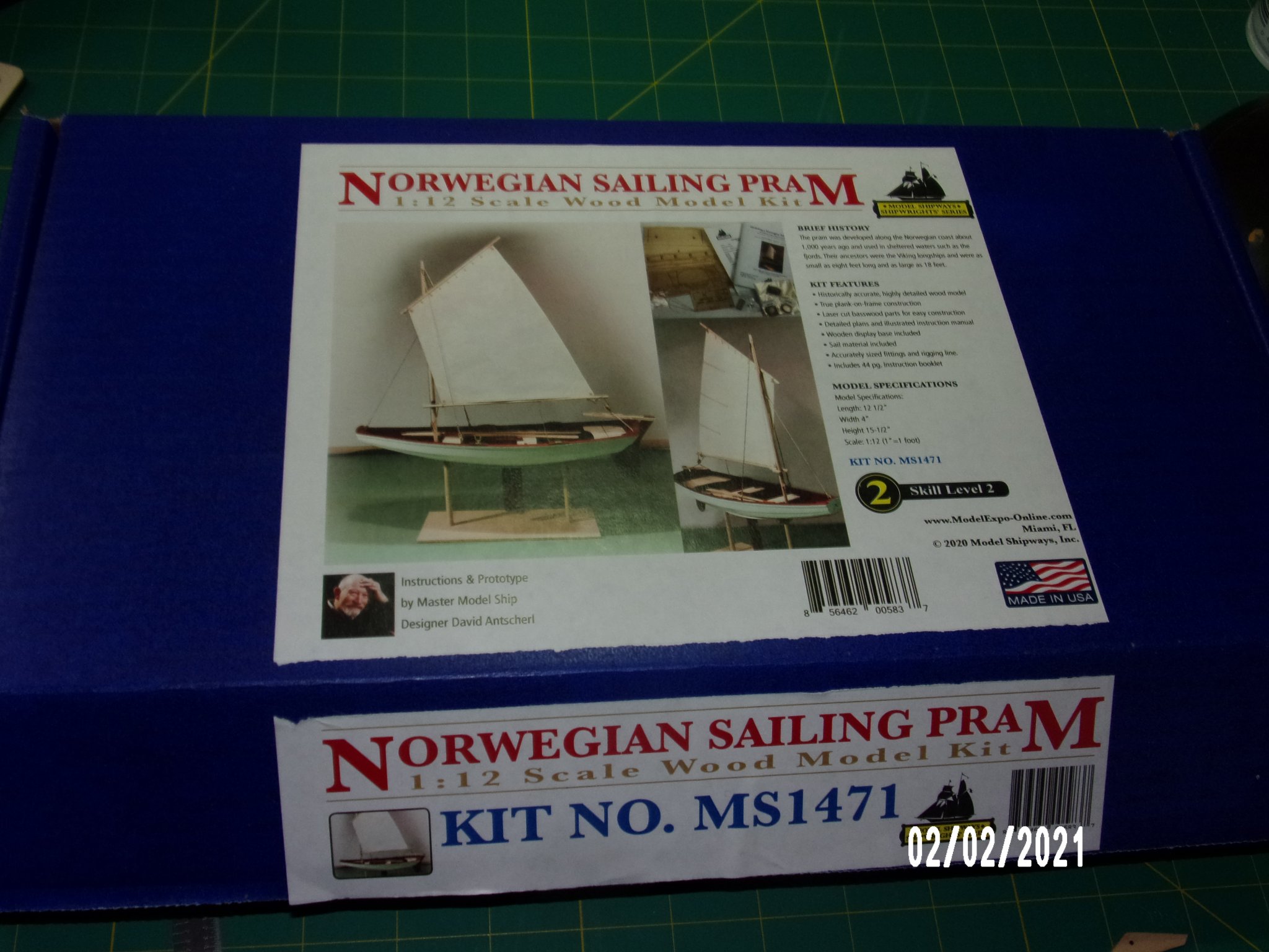
Norwegian Sailing Pram by bobandlucy - FINISHED - Model Shipways - Scale 1:12
in - Kit build logs for subjects built from 1901 - Present Day
Posted
Glued the three bottom planks on today and had a lot of problems. I'm not going to relate all the details, but the major problem was warping of the building board and inaccuracies in the molding frames as supplied. The building board and molds are inadequate in thickness as noted elsewhere, and there was a sizable error in centerline for molds-to-building board. I did a pretty good job in plank bending and don't think that stress from the planks contributed to the problem. I made some adjustments. I decided that additional attempts to correct might be more destructive than helpful. This is a learning kit, and I am learning. So, onward!