


Avi
-
Posts
320 -
Joined
-
Last visited
Content Type
Profiles
Forums
Gallery
Events
Posts posted by Avi
-
-
3 minutes ago, ERS Rich said:
? 🤔
Yup, little trick from @MrBlueJacket. CA is flammable. Metal is not. Use metal, when you need to, just burn it off, cool, wipe clean, reuse.
-
Thanks @ERS Rich!
I had been using an older glue looper. Side of it is flat, so great for spreading. I hadn't put dots in a a few places, but rather a line, then the side as a trowel, so I have a very thin layer across the whole back, except at the very edges, where it spreads a bit (but not out). When it is too build up, light it on fire, it burns out, ready to use again.
Your directions and suggestions are really worthwhile. I hope to do another 30-40 plates tomorrow.
- ERS Rich and Snug Harbor Johnny
-
 1
1
-
 1
1
-
Forgot to ask @JSGerson; how did you use the applicator? Most applicators, like the glue loop (the needle one you constructed is very similar), use some form of capillary effect. It is great to get a single shot of glue, but I found it very hard to work with to get onto a whole surface like the back of a copper plate.
-
@ERS Rich “burnish”? Do you mean to dry fit it and use the toothpick to shape the plate a bit? So it fits on precisely? That’s an idea worth trying.
the surface itself is plenty smooth. I’ve got the last coat of paint, it was sanded down with 2000 (if I recall correctly), and I even put a coat of CA on. Almost like plastic. And I know CA will attach very well to CA.
@JSGerson yeah that’s exactly it. Mind, I don’t have the tape, but rather the individual plates provided by BJ. I’ll admit it’s a major pain cutting them out, but at least they have the dimpling on one side and smooth on the other, so that’s not an issue.
I was so excited to start coppering finally, but didn’t quite expect it to be this tedious. Ah well. As @ERS Rich said, “persevere”. 😄
I do wonder how long they can stay open to the air before they start to oxidize. I’ve got museum wax to cover it all, which prevents that, but I obviously cannot apply until all the copper is done.
-
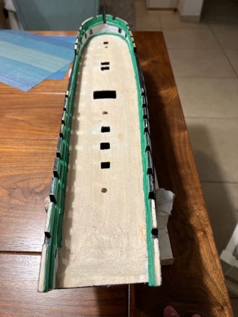
First sheets of copper in place. About 22 on each side of the keel. It looks nice.
I’m not enamoured of how the overlap part sticks outwards a bit. It feels like it will get pushed gently by a finger and come off.
Also the “put a drop use the capillary effect” did not work at all. I’m sure it’s my technique, but it didn’t work. I ended up putting a flat thin surface (think like a wide needle or very narrow knife blade) into the thin CA and then using the flat surface to spread it across the back of the copper sheet.

-
I’m about to start coppering. I spent quite some time yesterday evening rereading the posts and descriptions by @JSGerson and @ERS Rich, as well as both the MS and BJ directions and blueprints, and Marquardt. I’m fairly confident I understand it now (if not quite in my ability to execute, but that’s the story of building a model like this, learning anew at each step). So many thanks to both of you, as well as others who stepped in.
One last minute decision is whether to put down a layer of thin CA on top of the area to be coppered, ie where I planked and then painted copper (primed two coats, copper paint two coats, light sand in between, 4000 grit lightly on the final coat).
The guide recommends it, as did @MrBlueJacket. I like the idea, especially as it’s planked and could even the minor gaps (although maybe thick CA there would be better). I’m not sure how well thin CA and just copper plates (ie without a whole coat) would hold to the painted surface, vs how well I actually can apply an even coat of thin CA across the entire below-the-waterline section of the hull.
-
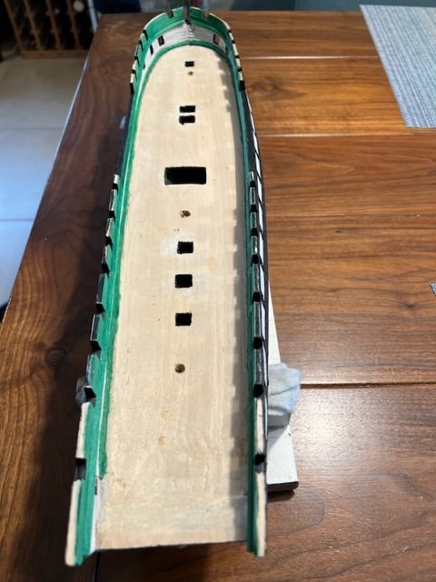
The camber of the gundeck was too extreme, but in some places the edges by the bulwarks were too low for the ports. It wasn’t just the angle of the guns, but the height of the gun itself.
Then I remembered that I had both the scribed decking that came with the kit, and glued up decking that I ordered.
I used a plane to flatten out the camber, leaving it much more subtle, and then sanded it to a reasonable smoothness. I didn’t need too high a grit, since it will be covered by the decking, just enough to make it smooth and even, started with 80, then 120, then 220, which was plenty.
When I’m ready to do the deck, I’ll lay down the original scribed decking first, then the glued up on top, which should elevate it to the right height. I’ll measure and cut many times first, of course. But that’s much later.
The guide has the gundeck and spardeck before the coppering, but since I need to invert the ship to copper, it’s *much* easier to do that first. So we shall.
I will reread the excellent assistance recommendations above, and the get started over the coming weeks.
-
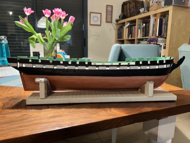
Did the black-green coat, I’m much more satisfied with it. Also touched up some areas on white where green bled out, and the spardeck gunports, where some primed areas had not been fully covered with black.
- mort stoll, KurtH, ccoyle and 2 others
-
5
-
Left (2DG) is current, 2 coats of Vallejo dark green. Middle is an extra coat of dark green (3DG). Right (2DG+1BG) is same 2 coats of dark green plus a coat of Vallejo black green.
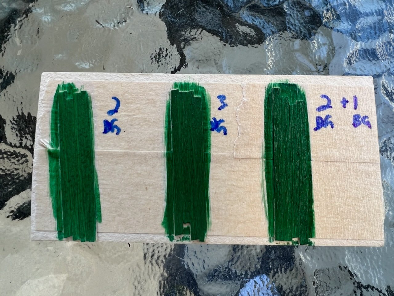
Time to show to my artistically inclined daughter. 😃
UPDATE: Both my wife and my daughter think that the rightmost one - a coat of black green on top of the two coats of dark green - is the best pick. The pictures may not do it justice, but the current one (2DG) is just too bright.
-
-
15 minutes ago, KHauptfuehrer said:
Model Shipways dark bulwarks green is considerably darker. My posts of Feb. 14 and 16 shows the color used on the port quarter boat and the bulwarks.
That’s quite helpful. Looking closely at your pics and my ship, they look just a bit darker.
I’ll take some strips of plank, paint to get like my current, then add a coat of black green to see.
-
1 hour ago, JSGerson said:
From your images, the green looks good to me. Like all painted surfaces, how it looks depends among other things, on the light source. Go online and find an image of the bulwarks in the full sun and compare that with your model under the same type of lighting. Then decide if you need to adjust.
Jon
I have my own pictures of it from Boston last May. Partly cloudy day. I will take the ship out tomorrow when the sun is out partly and look.
-
I kind of thought the green would be darker, more of a hunter green. I found the specific paints over a year ago, so I don’t remember how I picked Vallejo dark green, but that’s what my notes have. I also have their black green, maybe a single coat of that? Or a third coat of dark green?
-
Some pictures.
Yeah, I do know that the green bled onto the surface of the gundeck and onto the top of the bulwarks. But I don’t care. I’ve got planked decking going on the gundecks, and the caprail on top of the bulwarks, so I didn’t need to be too careful there.
- mort stoll, Ghost029, ERS Rich and 4 others
-
7
-
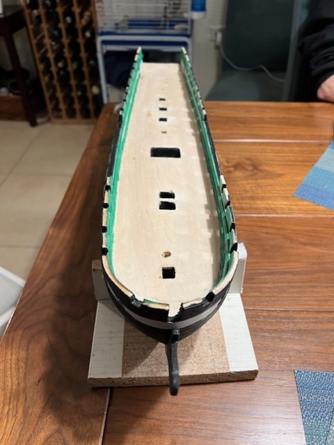
Finished the gundeck gunports black - people were correct; once they are done and painted, the slight differences in planking are well hidden unless you really look for them. This part was difficult though. You’re trying to get all four sides of something interior without getting paint on the outside. Needless to say, I didn’t succeed entirely, and had to put several coats of primer and white paint to cover up my errors. I probably could have sanded, but I suspect I would have taken off in other areas as well.
I also got the interior of the gundeck white. Next is green for the waterways and spardeck interior bulwarks.
Then on to protecting the exterior, trimming the gundeck surface some to reduce the camber, and coppering.
-
Haven’t posted in quite a while; some non ship related issues to deal with (oh yeah, work, too 😁).
I primed and painted the exterior all the way up, painted the black by taping off the place where the white stripe would be, and then reverse for the white. The tape never works 100%, mainly because of the bolt heads sticking out, I think, but very close. I fixed any leakage with a steady hand and very fine brush.
Next, I painted copper from the keel to the waterline. I didn’t bother taping there, as precision is less important; I’ll be coppering to a little above the waterline, ie above the black-copper boundary anyways.
I primed the gunports - spardeck and gundeck - and then painted the interiors of the spardeck ones black. I put a line of tape on the interior, so that the black wouldn’t leak onto the interior that should be green. It wouldn’t be the end of the world, I can always reprime the leaks, but it is easier and nicer if I don’t have to. To my pleasant surprise, it worked quite well this time. I also fixed all the areas where primer spread a bit onto the black on the exterior. Two coats of primer and two coats of paint everywhere.
I didn’t yet get to the gundeck gunports, as I ran out of time last session. Those will be next, then the interiors: spardeck green, gundeck white with a green waterway.
Pictures will follow when I have a chance.
-
-
@Snug Harbor Johnny quite detailed, but not sure what that has to do with coppering?
-
Oh good idea @KHauptfuehrer thank you. I’ve got the book of course and will look.
-
1 hour ago, JSGerson said:
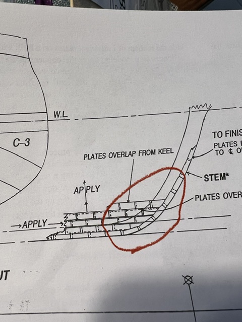
What the first diagram is try to convey is, as you apply the copper plates to the hull, you start at the stern and work your way forward and upwards overlapping the edges of of the previous aft plate as well as the plate below's top edge.
I understood that, but couldn’t figure out how that worked with the keel and stem plating. It looks like the stem plates overlap the horizontal ones (which fits with “from aft forward”), but those curve to the keel, which means either there’s a strange transition somewhere from “keel under next row above” to “stem over horizontal row”, or there’s no transition and the keel plates overlap the one above, which doesn’t fit with the directions.
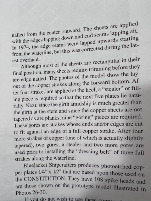
1 hour ago, JSGerson said:The second instruction is trying to state that because the plates are applied to the hull with no tapering unlike the wooden planks which are tapered. Therefore, sharp curves are going to be created at either or both the stern and bow. In order to minimize those curves a steeler, an extra row for a short length is added. The BlueJacket instruction is telling where a steeler should be placed. At each band, you in effect start a new horizontal uncurved row. The higher band cuts off the curving from the lower band. The diagram below illustrates a coppering method. I hope this helps and not confuse you more.
I think you’re saying that instead of tapering, as you go up, it will curve naturally, so at a certain point you stop going up and start a fresh horizontal strake which covers the curved one below? So what is the stealer? Is it a strake that is high on the band, and doesn’t make it all the way to bow or stern, just fills in the “gap” caused by the middle of the curve, so that the next strake - the lowest one of the next band, fully horizontal - will cover it?
-
Starting on the colours. Laying out the waterline in pencil - used the original template on cardboard (good thing I kept it) to mark the endpoints, then just connecting. As far as I can tell from the figure 30, the dressing belt straddles the WL, which means it goes above it. So I can paint black to the WL exactly and copper below and be fine.
Some things I didn’t understand about the coppering.
First, figure 30 shows the stem and keel plates overlapping the strakes. Is that correct? If so, does the keel also overlap the one above? If not, where do I stop the keel, and how do I transition from the keel (overlapped from above) to the stem (overlaps on it).
Second, I don’t at all understand this paragraph. “Stealer so that the the next five plates lie naturally…. Since the girth amidships is much greater than girth at stem… copper sheets are not tapered, nine goring pieces are required…”
I see three bands C1/2/3 and the dressing belt, but I do not understand how these all fit together.
-
Found a few planks that had come loose, good time to fix them up. Some of the bolt head nails also came out, so I put them back. Not too bad, fewer than ten. I redid those with medium CA. I think I might have done the spardeck topside heads with a slightly larger drill bit. That makes it easy to get them in, but loses the benefit of the wood pressure itself holding them in, and means that thin CA might not be enough. All in all, though, if I only had to redo ten, that’s pretty good.
As discussed above, no wood sealer, just two coats of grey Vallejo primer thinned 50/50, sanded lightly with 2000 grit in between (no idea where my 1000 went).
Letting it set overnight and then will start on actual colours.
-
The detail is really helpful @ERS Rich, thank you.
I don't have a spray gun, not all that interested in getting one at this point. I will live fine with the hand painting with various brushes.
I have mostly Vallejos, but have been thinning about 50/50, maybe a little more than that. So I will try the top coat with less thinner. I have plenty of planks on which to experiment.
-
@JSGerson so you pressed the entire plate of copper on some coarse grained sandpaper (80 grit? Higher?), and then just pressed the teeth of the mitre saw just inside of each of the four edges? Is that it? What does that look like?
Actually not sure how much I need it. I’ve got the copper plates from bluejacket, which have the texture on them already; see pic.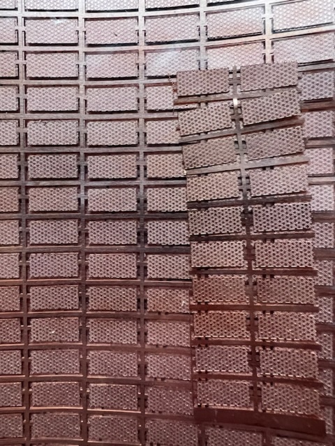
USS Constitution by Avi - BlueJacket Shipcrafters - 1:96
in - Kit build logs for subjects built from 1751 - 1800
Posted
Oh! I think we interpreted "it" very differently. When "it builds up" means "builds up too much on the glue tool (needle, glue looper, trowel, etc.). I am not lighting the copper plate.
> Interesting, in the photo, the same aft plate edges are lifted.
What do you mean?
I had several plates (5-7) come off today, had to redo them. Did another 20-30 or so, finished the keel on both sides, started second strake on starboard side. I think I might try the medium thickness CA glue next time. I had much better luck with it when doing planking.
I was working with the thin glue today, didn't realize where some had dripped. Lifted and found my thumb and index finger stuck together. Oops. Was only 30-45 seconds, but with thin CA, that is plenty. Took a lot of debonder to remove it, but I did. 😆