Dan Vadas
-
Posts
3,261 -
Joined
-
Last visited
Content Type
Profiles
Forums
Gallery
Events
Everything posted by Dan Vadas
-
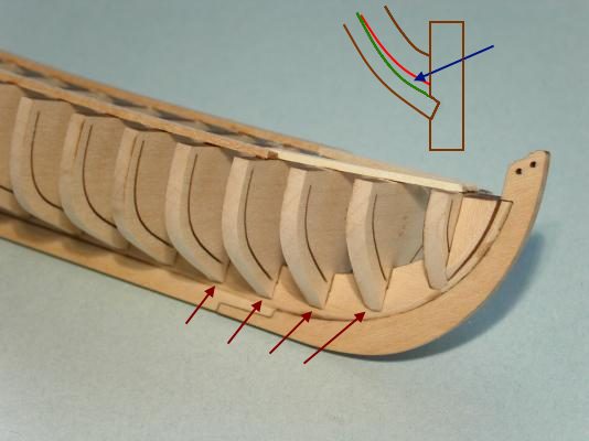
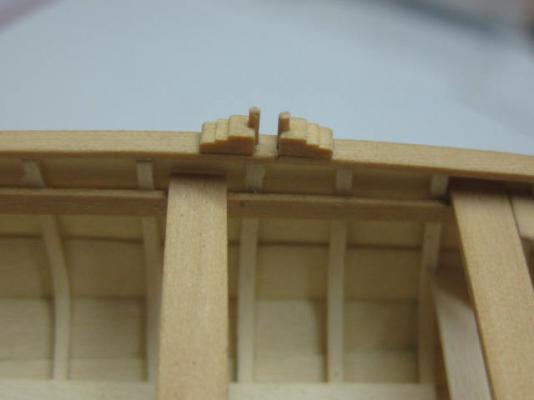
Hi Erik, Looks good so far, except that you may have taken a bit too much off on a few bulkheads. This may be just camera distortion, but it's a little hard to tell. To explain, take a look at my modified pic : It appears that the arrowed frames follow the red line in my little drawing, whereas they should be on the green line for the planks to sit in the rabbet correctly. It's no big deal to fix - simply glue some scrap timber into the offending areas and sand back to the correct line. The glue joints will be invisible later as the footwaling will cover them. This is a critical area of the hull to get right - the Garboard plank starts around frame #3 and needs to sit correctly for the rest of the planking to follow. Danny
- 222 replies
-
- 6
-

-
- 18th century longboat
- model shipways
- (and 2 more)
-
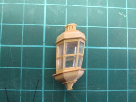
Thanks very much Greg, John, Nils, Jan, George, Russell and Pat . Jan - it's 28mm tall. Russell - Because I could . I don't doubt the PE one would be accurate though. Vulture only needs the one. Here's the finished job. I've just now given it a coat of Minwax which hasn't dried yet : Danny
-
How would you improve your Byrnes tools?
Dan Vadas replied to Keith_W's topic in Modeling tools and Workshop Equipment
Hi Keith, No worries. It's interesting to see how others have made their own improvements or given tips on how to get the most out of them anyway . Danny -
How would you improve your Byrnes tools?
Dan Vadas replied to Keith_W's topic in Modeling tools and Workshop Equipment
Umm .... Grant - as far as I'm aware you CAN'T solder aluminium. MIG or TIG welding is the way to go. Otherwise I'd suggest using brass instead for both the clearance plate and knife, which as you know can be silver soldered. Saw - 1. The above-mentioned Riving Knife. 2. A lock on the drive shaft to make changing blades easier. I use a pair of Vise Grips to hold the shaft when I'm undoing the blade nut. I used the supplied Clearance plate to make a "Zero Tolerance" plate for the 0.020" blades by simply removing the plate, turning it around, scewing it back down, and then raising the blade (with an old one installed) to cut a new slot alongside the existing one. It works great on very small/thin pieces as they don't disappear down the slot . I also CA glued a strip of 2mm thick timber to the fence at virtually zero height from the bed. This makes cutting very thin stock possible, as the existing fence clears the bed by about 0.6mm and anything thinner went under it. Sander - 1. A Forward / Reverse switch so you can sand from either side of the disc. This would make sanding the same angles in both directions much easier, among other operations. 2. A tilting table that goes a full 90 degrees instead of the current 45. Same reason as above. It only takes me a couple of minutes to change the paper. I remove the table and the lower cover, then use a razor scraper to get the paper off the disc. Final cleanup of the remaining glue/paper is done with Turpentine. The only mod I'd like to see for this operation is a pair of thumbscrews holding the bottom cover instead of the Allen Head screws - it would save about 30 seconds when replacing the paper. Drawplate - 1. Some of the holes have increments of more than one size step. When you get to one that is two (or THREE) sizes smaller it makes it rather difficult to start the next "pull", especially in the smaller size holes. Perhaps as mentioned above a second size of drawplate with the larger holes would be of benefit, with all the holes in BOTH plates decreasing in size by ONE number. 2. The laser-etched numbers are on the wrong side of the plate. Some times it's easy to forget which hole you are using, or comes next, without turning the plate upside-down for a look. Danny -
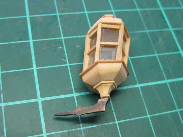
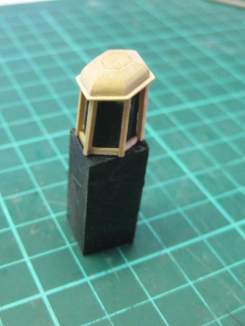
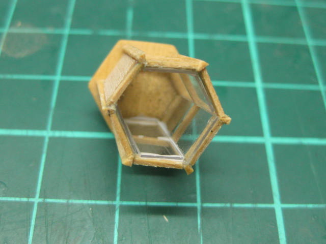
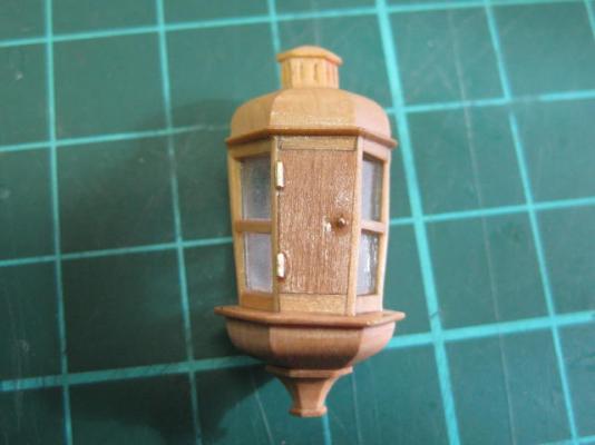
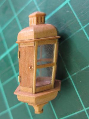
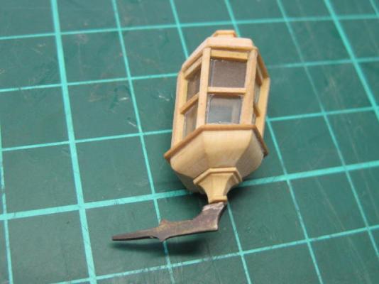
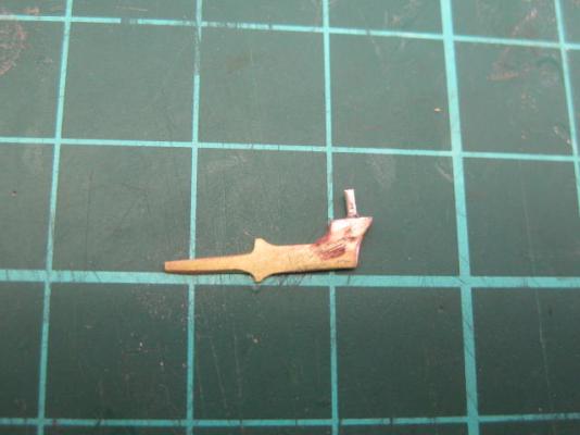
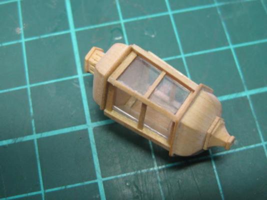
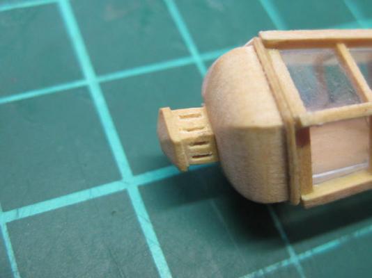
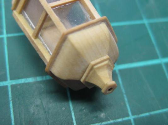
Thanks Greg. .... continued. Here's a pic of the progress. The base has been fitted to the munions : The Stool was a challenge : There are several rims between the pieces. I glued each piece to some 0.5mm thick stock and sanded the edges to shape when it dried. This was then rounded with a sanding stick : The centre munions were fitted next. There is still some sanding to be done to get the verticals down to size in this pic. The "glass" (acrylic) has been fitted : I filed the Crank from brass strip and soldered a mounting pin on : Nearly finished. I'll sand the edges of the verticals down to size tomorrow when the glue is completly dry : The Vent : Detail of the base and stool : With the crank fitted : Danny


-
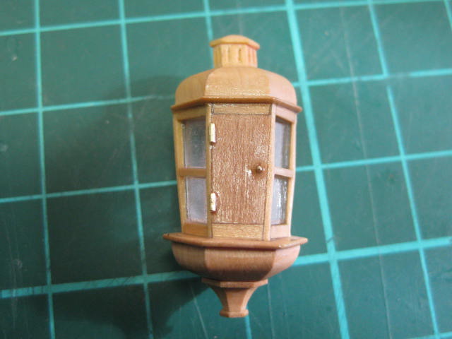
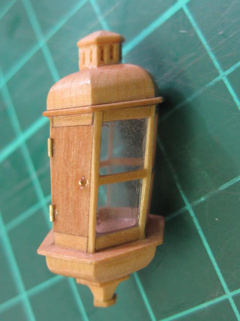
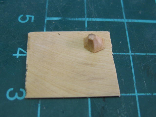
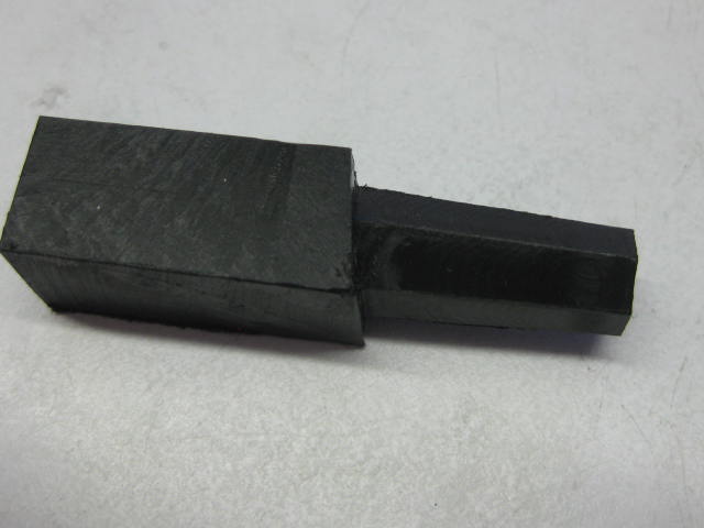
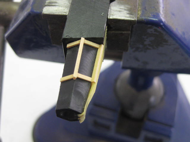
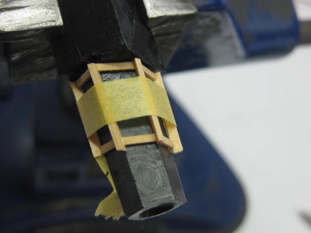
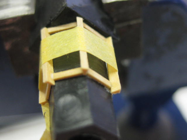
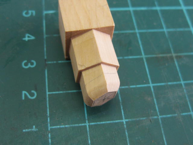
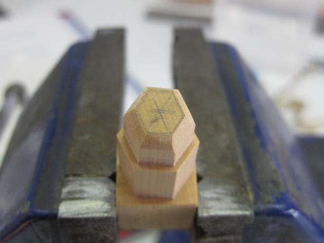
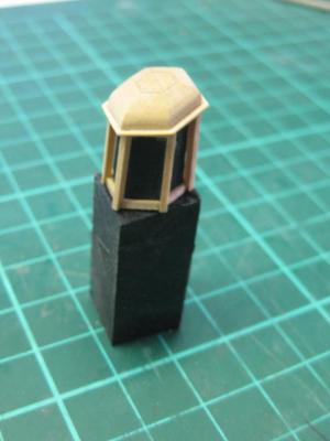
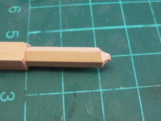
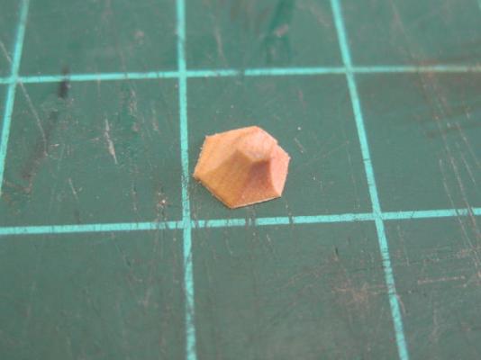
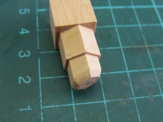
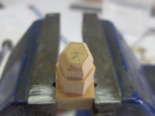
Lantern The construction of the Lantern begins by milling a plug around which it will be built. I used plastic which had a quite slippery surface to prevent as much glue as possible from sticking. The lantern is tapered from top to bottom and is also at a 15 degree angle from the vertical. I used the dividing head shimmed up to the 15 degree angle on one end : The vertical munions are cut to 30 degrees on the edges. They are left overly thick whilst assembly goes on, I'll trim them to the right thickness when all is assembled : The top and bottom are rather tricky to shape, as the 15 degree angle applies again but they are also rounded. I milled the hex to the angle and rounded them with a sanding stick : Continued next post .....


-
Hi Al, They sure do - check on the Index Page of MSW. They are owned by our own Chuck Passaro. Danny
-
anyone built San Juan Nepomuceno (moved by moderator)
Dan Vadas replied to ger.sec's topic in Wood ship model kits
Hi Gerry, and welcome to MSW. Here are the links to four of the five build logs mentioned by Captain Steve. The other is the barge from the same ship : haughtonb kostas augustus Juan Barge by Kenway Danny -
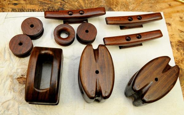
Hi Al, It's pretty good scale, except that I've rounded off my blocks a little too much in one direction. These blocks are only 3mm (top)and 3.5mm. The rope is 0.3mm from Syren Ship Models. A bit of both, depending on which part of the groove the strop is lying in. To explain take a look at this pic of blocks under construction (not my work ). Note the shape of the "groove" : Danny
-
I don't : Danny
-
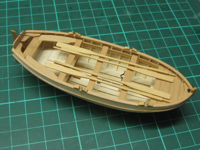
Finished The Cutter is finally finished. It's taken me just under 3 weeks to build. Danny


- 62 replies
-
- 32
-
-
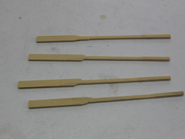
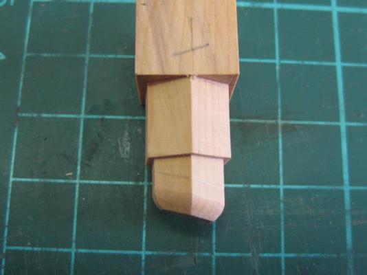
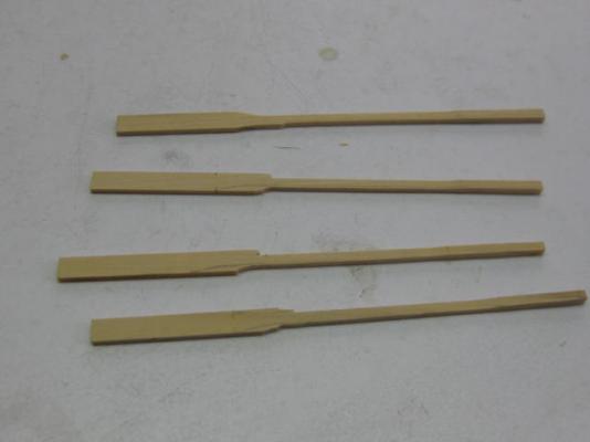
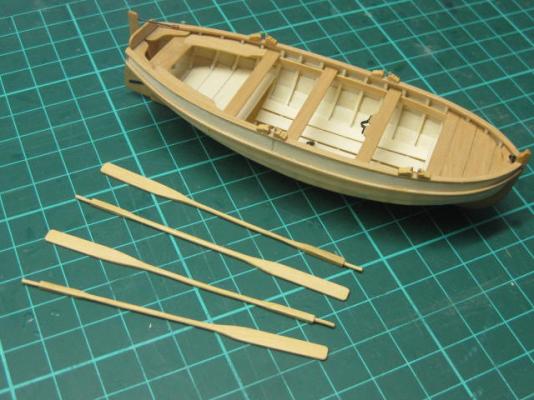
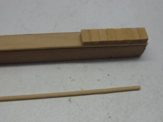
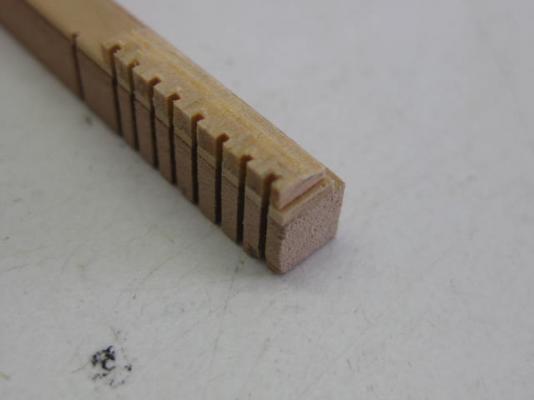
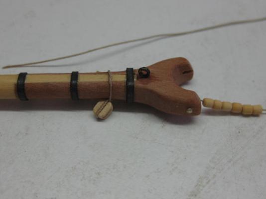
Oars I made the oars from English Box. The Byrnes thicknesser and sander did most of the work, the rounded middle section was done in a similar manner to shaping masts and yards. The first pic shows the oars before any hand finishing started. The square thicker section near the handgrip acts as a counterweight to make rowing easier. Danny
- 62 replies
-
- 14
-
-
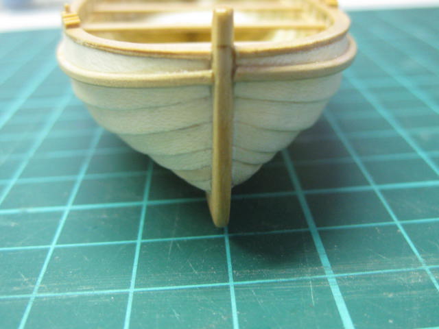
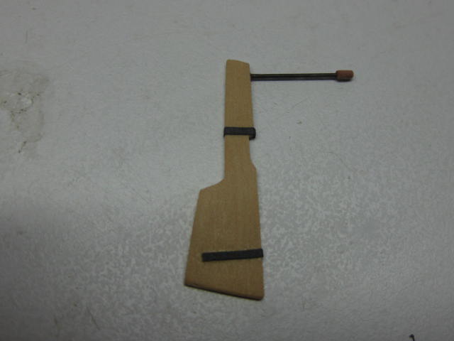
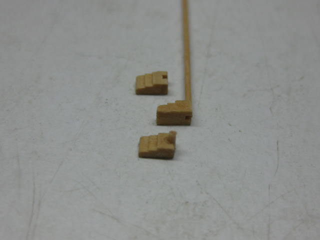
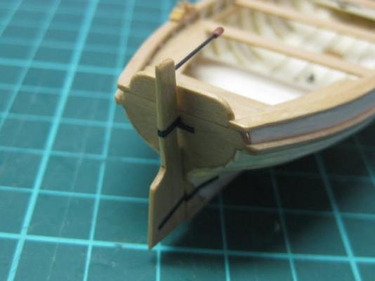
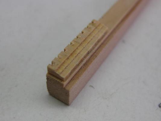
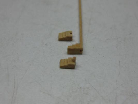
Rudder and Tholes Here's a pic of the Rudder. The hinge straps are paper coloured with wood stain. The hinges themselves are non-existent, the rudder is simply glued to the transom : The Tholes are the period equivalent of rowlocks. I made the support braces using my "mass production" method - most of the shaping work was done on the Byrnes saw, the final rounding done was done with needle files : Danny

- 62 replies
-
- 16
-
-
Thank you John - I had an idea you may have been lurking on this build . Russell - I was only quiet on the computer. It was doing it's "hissy-fit" thing again for the past week or so, making posting very difficult. I've actually finished the Cutter, more posts are about to follow. Regarding the "1mm" ring - I wrapped the wire around a 1mm drill to roll it round. The drill bit is only a cheapie and actually measures 0.098mm . Danny
-
Hi Al, There is more "cheating" going on than you can imagine . I don't regard it as cheating if the end result looks like the "real thing". Your idea if making a continuous loop is pretty much the way I do it . Regarding PVA - all of the above . CA just doesn't do the job, plus it's too unpredictable as regards drying time - most times it doesn't give you any time to "work" a knot. Another plus for PVA is that it allows you to easily undo a knot (using Isopropyl or just plain water) if you need to make a later adjustment. Danny
-
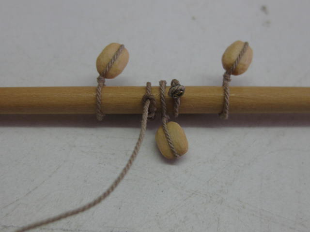
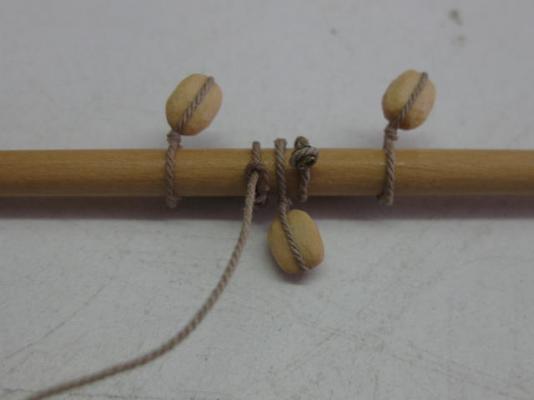
Looks OK Al. You've got the seizing pretty near perfect. I've worked out a pretty easy "cheat" for tying the smaller blocks that don't have eyes in their strops. 1. Simply tie a single overhand knot around the spar with the knot part on the opposite side to the block. Only pass each end of the strop around the spar ONCE. 2. Brush liberally with slightly diluted PVA. Trust me, the glue will hold perfectly well without the need for a more complex knot. 3. Let the glue dry thoroughly. 4. Last trim the tails carefully on a sharp angle almost parallel to the strop with a SHARP Xacto or scalpel. The end result looks like the strop has been spliced around the yard . Look carefully at the top of the strop in the pic below to see what I mean : Hope this helps. Danny
-
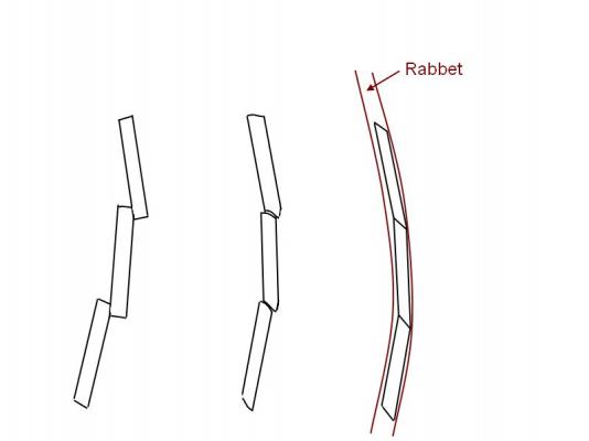
Thanks very much for the kind replies Christian, Greg, George, Johann, John and Highlander. They are much appreciated . Christian - no, I won't be building the Pinnace. Johann - that's some seriously good work you are doing on your Longboat . John - It took me a while to understand the purpose of the Rolling Bevel as well . Highlander nearly got it right, except that the bevel only rolls for the last couple of (scale) feet from the bow and stern. Picture the Rabbet - it's a parallel groove the thickness of the planks, whereas the clinker planking overlaps each plank by a couple of (scale) inches. As the plank approaches the bow (or stern) it needs to transition from Clinker to Carvel, hence the "Rolling Bevel". The diagrams below may help explain how it works - they are copied from the Cutter Instructions written by David Antscherl : Danny
- 62 replies
-
- 12
-
-
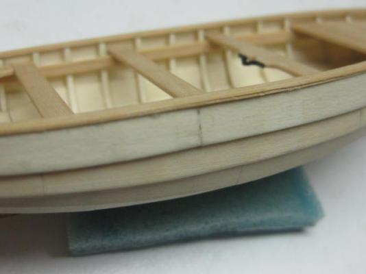
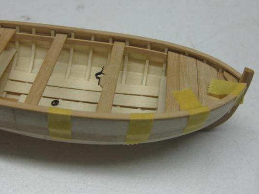
Gunwales I cut the gunwales from a single piece each side after first tracing around the upper hull. A compass was used to get the inner edge parallel. It is 2.5mm wide : It's a bit hard to see in these pics, but I've scribed a small moulding into the outer edge : Masking tape was used to hold the gunwale down while the glue dried : The completed gunwales : Danny
- 62 replies
-
- 28
-
-
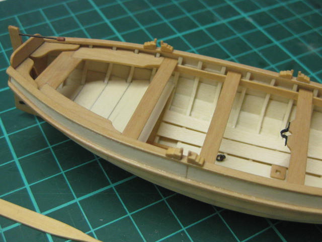
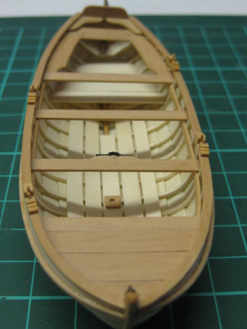
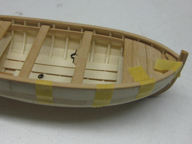
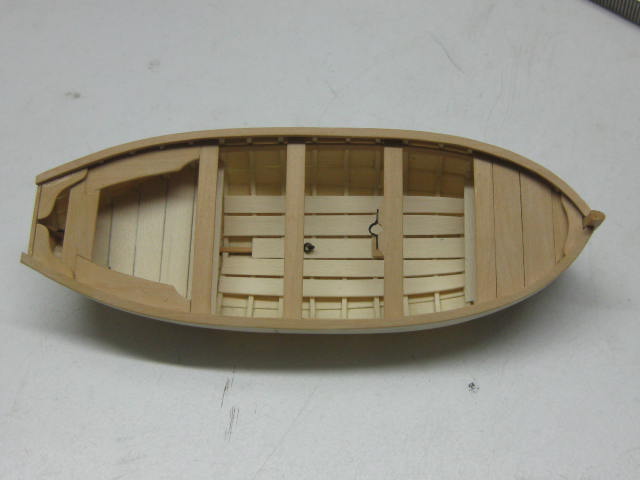
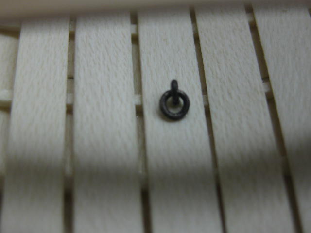
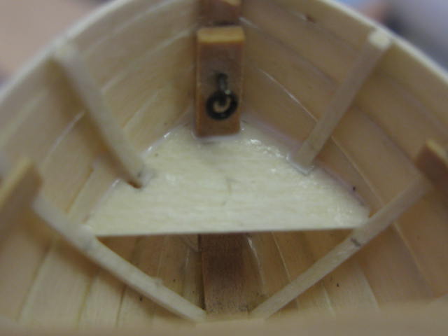
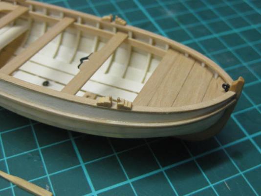
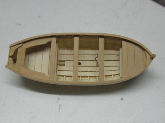
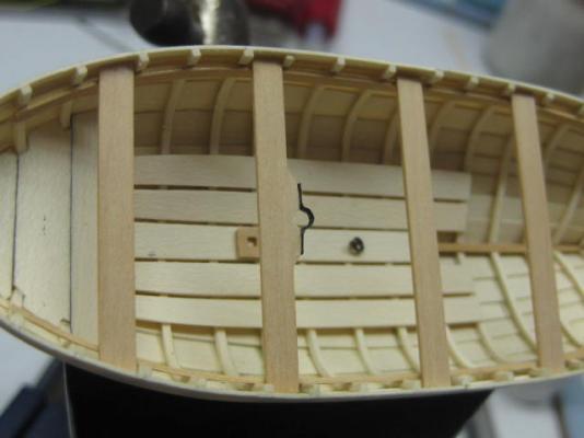
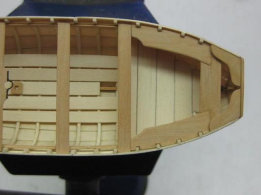
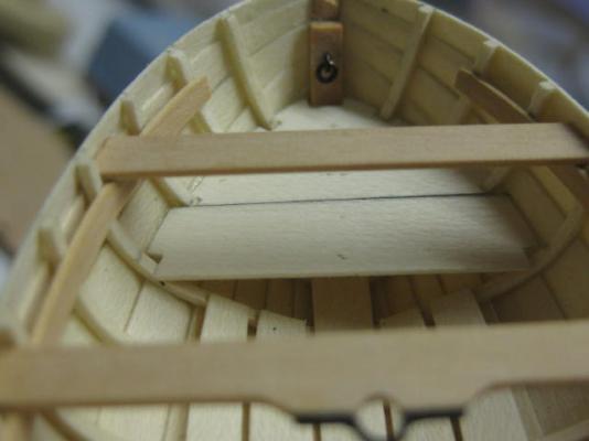
Thwarts The Thwarts are next. The central one is fitted with the clamp that holds the mast, and a step is fitted to the keelson below it : The Stern Sheets and Knees : The upper fore Platform and Breasthook in the bow : There are three eyebolts and rings fitted, one each in the stem and sternpost and one amidships. These are the smallest ones I've made so far - 0.35mm wire, the ring is 1mm inside diameter : Danny

- 62 replies
-
- 23
-
-
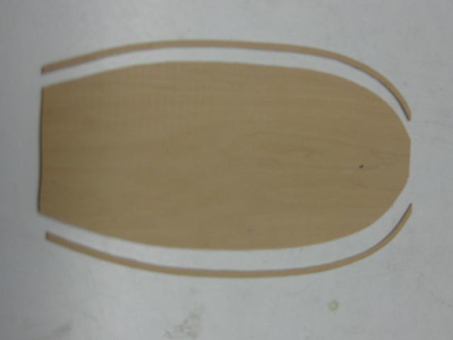
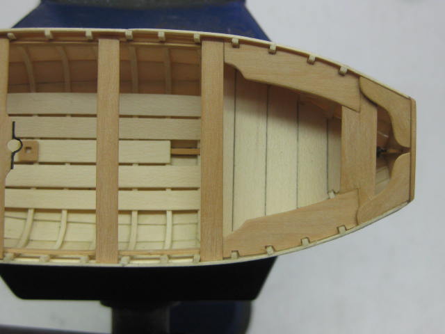
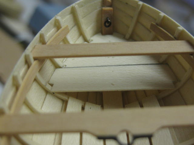
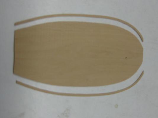
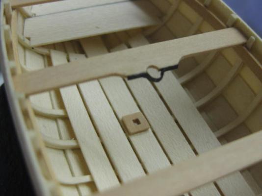
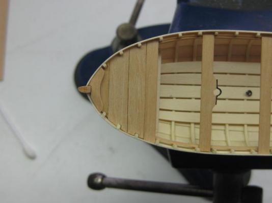
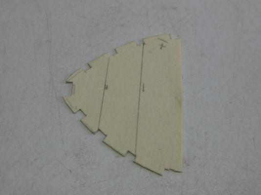
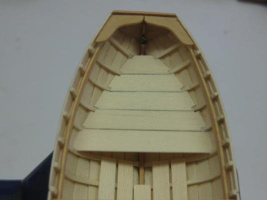
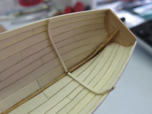
Next jobs were the Fore and Aft Platforms. Card templates were made for both : The first plank of the fore platform. The glue has just been applied and not yet cleaned up : A pic of the fore platform at a later stage of the build : The aft platform. The Knees have also been fitted in this pic, but I later removed them to fit the stern sheets (seats) : Danny

- 62 replies
-
- 15
-
-
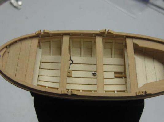
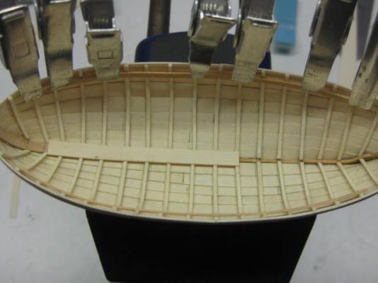
Thank you Nigel, Greg, Maury, Nils and Popeye . The ribs have all been installed, and also the Keelson. I'm in the process of fitting the Risings which support the Thwarts (seats) : Danny

- 62 replies
-
- 16
-
-
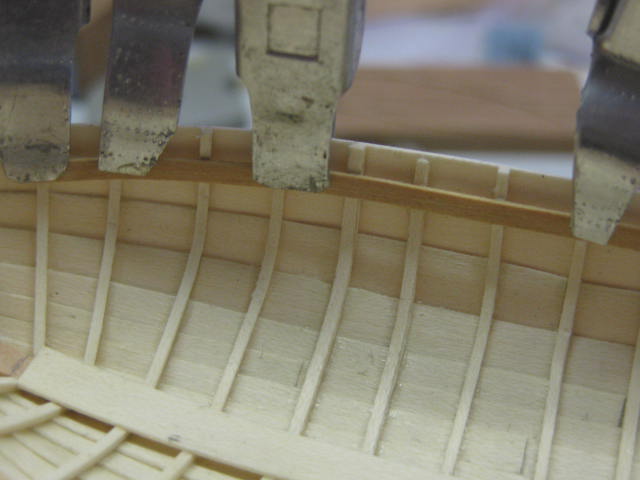
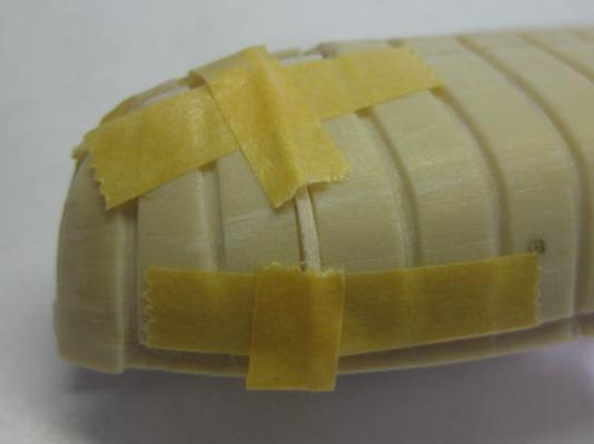
Thanks George, Mark, Russell (you didn't have to wait long ) and Janos . Ribs I used the plug to form the 1/32" square ribs, once again using Tamiya tape to hold them in shape while they dried. The Tamiya tape holds onto the resin plug very well, and is easy to apply using the tape holder/cutter. The tape is 1/4" wide : A couple of hair clips hold the rib in position whilst the glue dries : The aftmost rib. The tops of the ribs will be trimmed when they are all fitted : Danny

- 62 replies
-
- 18
-
-
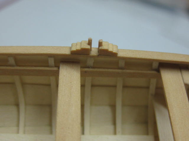
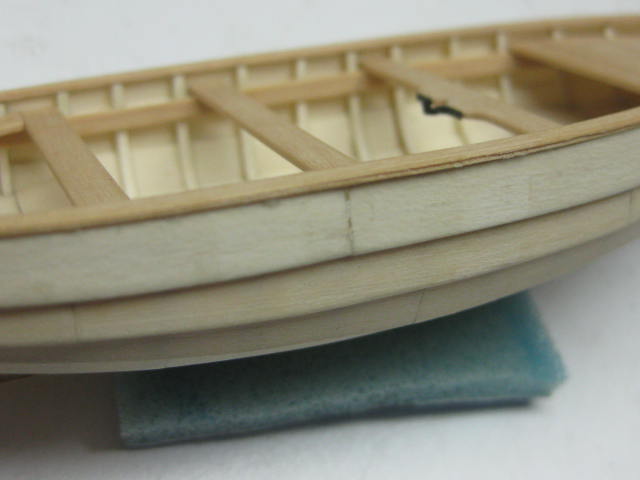
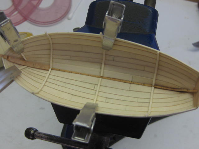
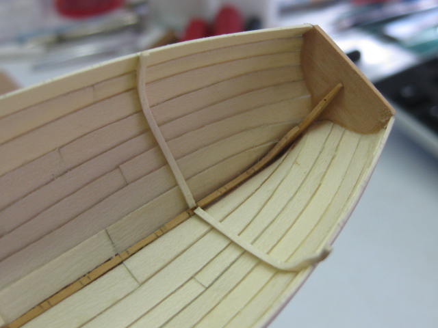
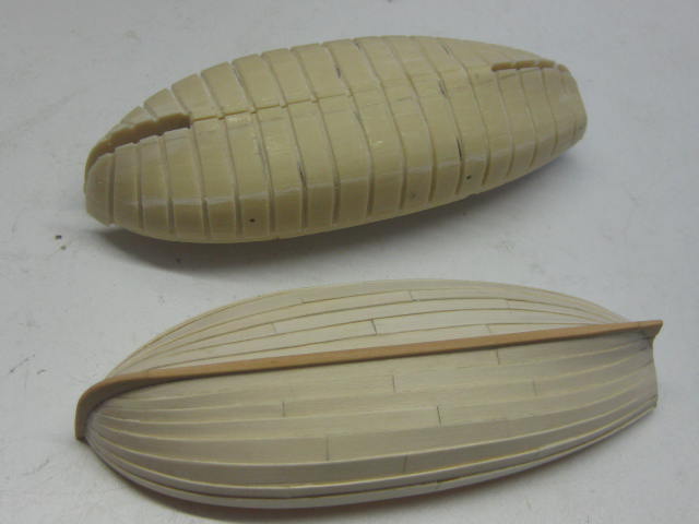
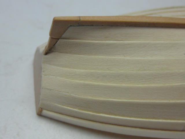
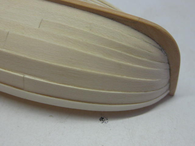
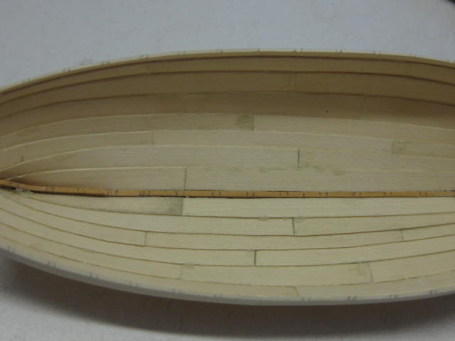
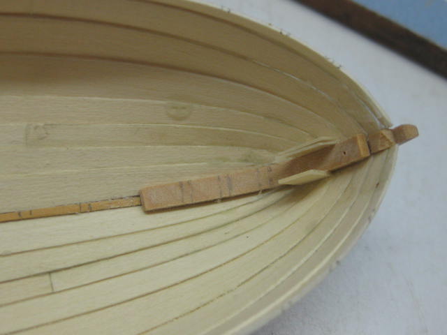
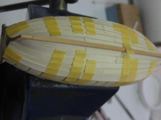
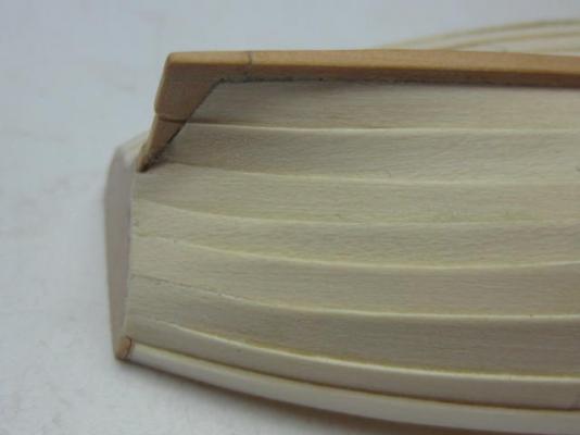
Planking As suggested in the instructions I've planked the hull of the cutter without the ribs - they'll go in later as most of them would come off the planking when the hull is removed from the plug. This pic was taken with a couple of runs left to do. I'm using Tamiya masking tape to hold the planks in position while they dry : The cutter removed from the plug. It came out very easily : Some pics of the outside. The planks need a "rolling" bevel both fore and aft to fit to the stem and transom : There was very little excess glue inside the hull. These pics were taken before I started any cleanup : You can see a couple of wedges in the bow which I inserted to ensure a tight fit to the plug. Isopropyl alcohol made removal of them easy : Danny


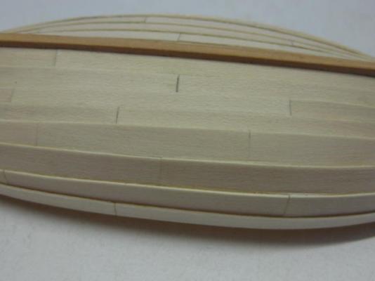

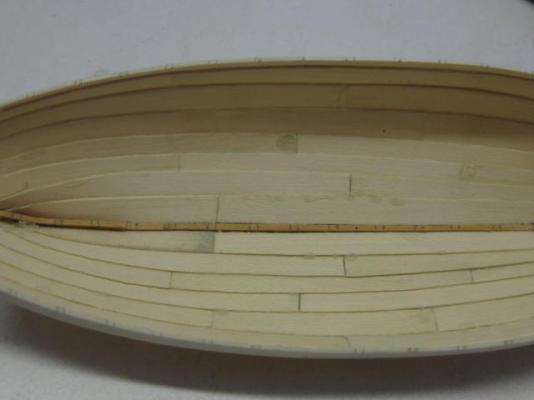

- 62 replies
-
- 25
-
-
New kit in the market: HMS Sirius
Dan Vadas replied to Ulises Victoria's topic in Wood ship model kits
Not really Chris, all I can find on Google is the Tourism bit which doesn't really show too much . http://norfolkislandmuseum.com.au/exhibitions/hms-sirius/ http://norfolkislandmuseum.com.au/collections/hms-sirius/ Danny -
New kit in the market: HMS Sirius
Dan Vadas replied to Ulises Victoria's topic in Wood ship model kits
There is a scratchbuilt model of HMS Sirius in the Norfolk Island Museum, as well as one of HMS Bounty. I'm not sure of the scale but I think they're 1:24 (big ). My model of HMAT Supply is in the same museum. Danny