Dan Vadas
-
Posts
3,261 -
Joined
-
Last visited
Content Type
Profiles
Forums
Gallery
Events
Everything posted by Dan Vadas
-
New kit in the market: HMS Sirius
Dan Vadas replied to Ulises Victoria's topic in Wood ship model kits
To mine too Frankie - the bowsprit should be about the same diameter as the foremast, which it clearly isn't. Danny -
Thank you for commenting Greg (yep, 1:48 scale), George, Jan, Maury, Toni, Druxey and Ken. You're doing a very good job on your Cutter Maury. I have your Build Log open as I'm working on mine - you've already saved me a couple of times . Yes, my plug has the planking marks. Instead of marking the other side I'm cutting two planks at a time - the 2nd should follow the line of the 1st. Druxey - my plug was a whole 5mm longer than the plans - I had to modify my keel to suit as I didn't want to muck up the lines. Ken - permission granted . Danny
-
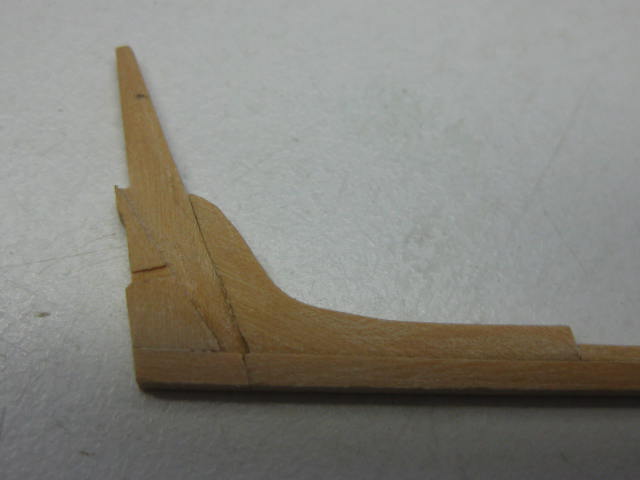
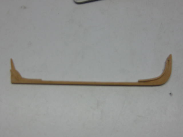
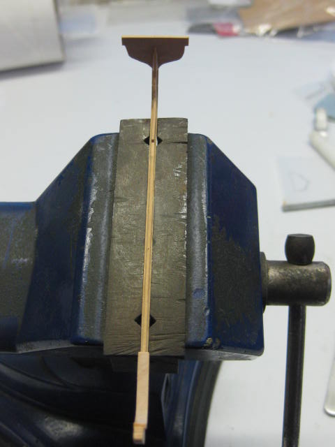
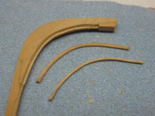
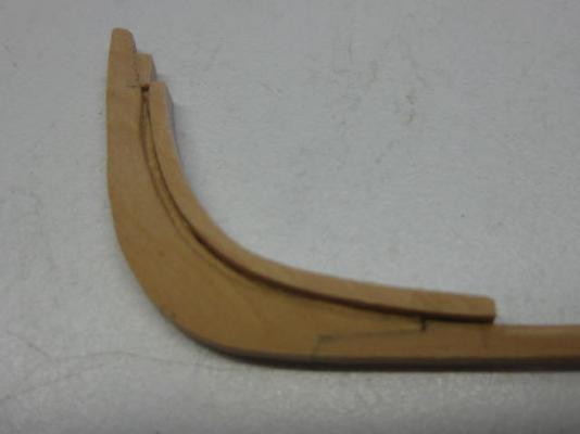
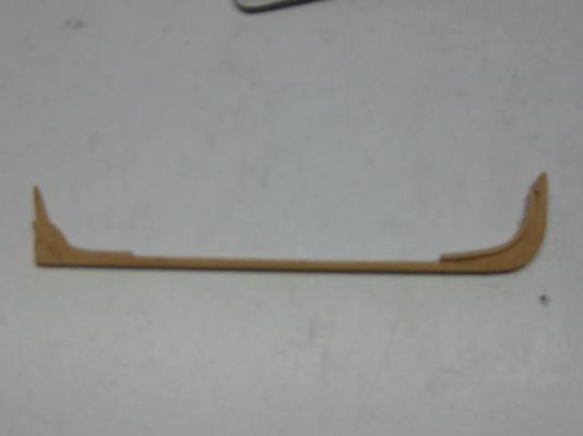
Keel The Keel assembly consists of 6 parts - the Keel itself, the Stem, the Apron, the Sternpost, the Sternpost Knee and the Transom. A rabbet is cut in the length of the keel. I used an Xacto knife and a straight-edge to cut this. The Xacto was also used to cut the rabbets into the stem. I managed to cut both of them without actually breaking either off-cut (just to see if I could ) : The Apron is 2" scale inches wider than the stem. This was cut with the scroll saw : The Sternpost is also rabbeted, and the cutout for the rudder pintle and strap have been cut in : The keel assembly : After some minor cleaning up the Transom is glued on : I found a problem with the length of the plug and the plans - the plug is 5mm too long! I had to adjust the length of the keel to suit. This is now a 18'9" cutter instead of 18' . Danny


- 62 replies
-
- 15
-

-
Thanks for dropping by Greg, Popeye, Christian, Toni and Maury. Perhaps Admiralty Models may still have some? I might build a 2nd Cutter for the fun of it as a separate model, but I'm only going to fit one onto Vulture. Anything more specific about the problem Toni? I'd like to know before going much further, as I'm about to put the backbone into the plug. Danny
-
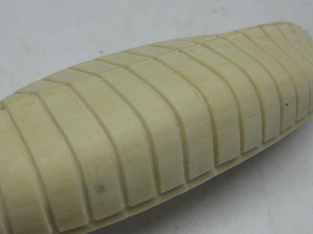
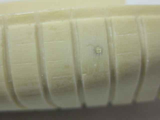
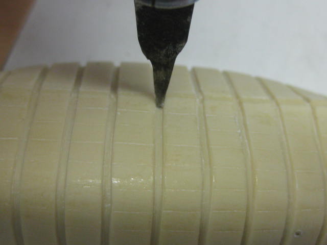
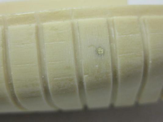
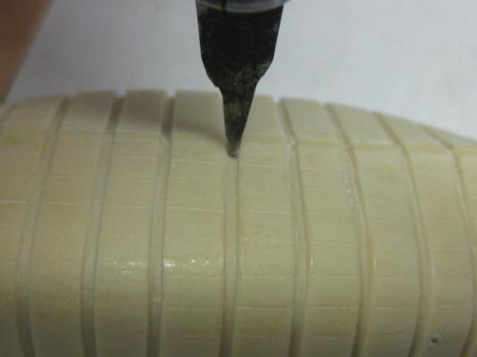
Thanks Russell. First job is to get the Plug ready. This comes in 3 pieces, two hull halves and a removable piece in the middle to enable it to be removed from the framing later on. I drilled two 1.2mm holes through all three pieces whilst holding the whole thing together in the vise. Then I inserted two lengths of brass wire to keep everything in line : I gave the plug a light sand to remove any lumps and bumps. Due no doubt to some limitations in the casting process the grooves for the frames weren't perfect, so I used a narrow chisel blade to scrape them out : Danny

- 62 replies
-
- 14
-
-
Welcome guys . I remarked earlier on that there were no Instructions for making this boat. Thanks go to David Antscherl who emailed me the complete set . He'd pulled the Instructions from the Admiralty Models site when the Timbering set was no longer available. I don't know how I'd have got on without them - there are 19 pages of beautifully written instructions, complete with pics and plans. I expected nothing less . Danny
-
Thanks for looking in John and Michael . With work on the rigging at a standstill for a week or so I've decided to make a start on the Cutter. I'm going to do this as a seperate Build Log which can be accessed HERE. Danny
-
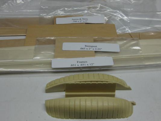
Hi all, I have started work on the Cutter for my model of HMS Vulture (link in my signature below for those who haven't seen her) and decided to make a separate Build Log of the project. Some time ago I purchased the Timbering Set for this model from Admiralty Models. Timber in the set was cut by HobbyMill who are no longer in production, so I don't know if the Set is still available. EDIT - It's not. The "kit" includes a resin plug to which the frames are temporarily fixed until the boat takes shape. There are NO plans or instructions included - this "kit" is even more in the way of Scratchbuilding than the ship itself is. Here's a pic of the "kit" : There are 5 packs of timber (not sure of the type) ranging in thickness from 0.031" to 0.1" for things like the Keel, Transom, Gunwale and Thwarts. There are also 2 packs of Holly - one is 0.031" x 0.031" for the Frames, the other is a sheet of 0.015" thick for the Planking. All the timber has been milled to HobbyMill's exacting standards and looks to be of excellent quality. There also seems to be a lot more timber than I'll need - probably enough to make TWO Cutters if I don't waste any . Danny
- 62 replies
-
- 14
-
-
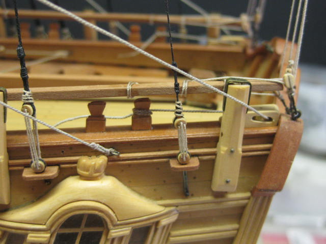
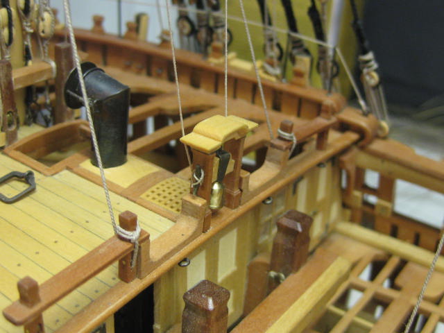
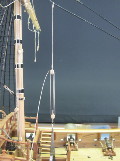
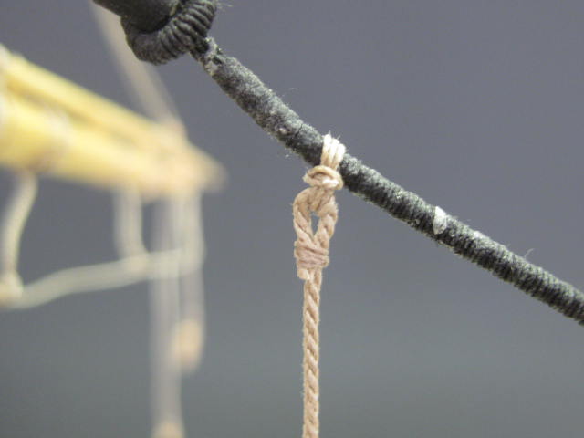
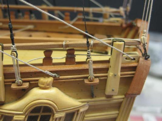
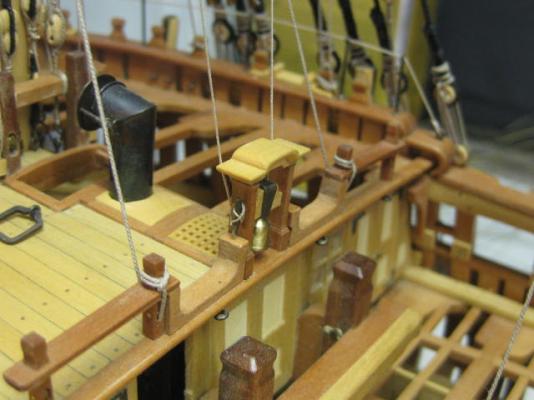
And thank you George and Jack . The Main Braces start at an eyebolt above the quarterlight. The halyard then reeves through the pendant on the yard, back through the fixed block near the taffrail, and belays to the aftmost timberhead : Danny

-
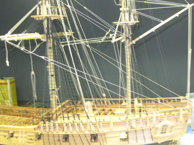
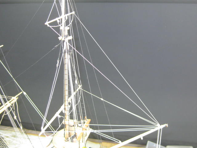
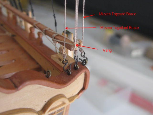
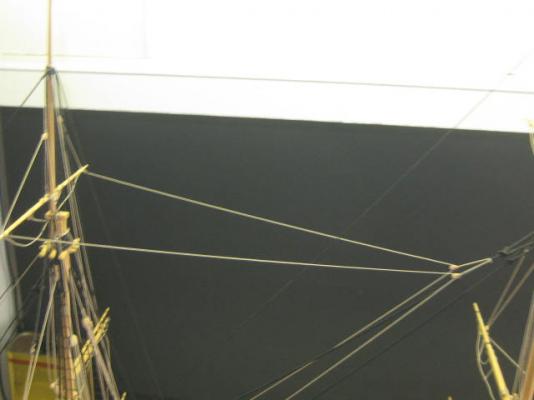
Thanks George. Maybe it's because they are among the last bits of rigging you fit? . I still have a few more to go, as I've found it easier to start at the stern and work forward. Braces I've fitted most of the Braces, which control the fore-aft swing of the yards. I've come to a slight stand-still as I've run out of 0.3mm line (I'm less than 1 metre short, but have to wait a week or so to get some more from Chuck). The first ones to fit are the Topgallant Yard Braces, starting with the Mizzen mast. These are seized around the yard without a Pendant (all topgallant braces are similar). The brace runs through a double block fitted near the peak of the Gaff, through a lead block hooked to the taffrail, and belays to the quarterdeck rail : Next come the Mizzen Topsail Braces. The halyards are attached to the strop of a block each side of the peak of the gaff, reeve through the blocks in the pendants, back through the first blocks, and belay off in similar fashion to the topgallant braces. The Main Topgallant Yard Braces run through Pendants hitched around the Mizzen Topgallant Mast. The brace goes straight down to deck to belay to the quarterdeck rails : The Fore Topgallant Yard Braces run through the pendants attached to the Main Topmast Stay, forward through two blocks hooked to the aft end of the fore top, and go to deck to belay at the cleats either side of the Belfry : The Main Topsail Yard Braces make use of a Pendant clove hitched around the mizzen mast just above the Crossjack. The standing ends of the halyards are hitched to the strops of the pendants, reeve through the blocks in the pendants on the yard, back through the first block, and belay to cleats at the foot of the mizzen mast : I can fit the Main Braces, but the other two Fore Braces will have to wait until my rigging thread arrives. Danny


-
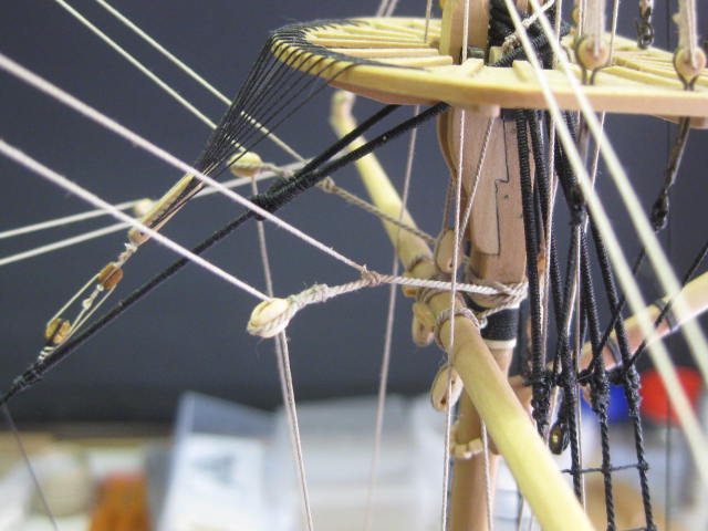
Thanks guys. I'd keep the door shut if I HAD one - no such luck . Pud stays outside while I'm working on the ship, but we have to let him in overnight (winter and all that ). Vangs The Vangs control the swing of the Gaff. They are clove-hitched around the end of the gaff, and the falls reeve through a lead block hooked to the taffrail and belay to the quarterdeck rail. In these pics the Mizzen Topsail and Mizzen Topgallant Yard Braces have also been fitted : Danny


-
Thanks guys, but the pics above only show the damage, not the repairs (there was damage on TWO masts). Here are the repairs : Danny

-
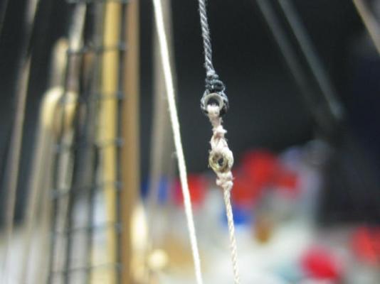
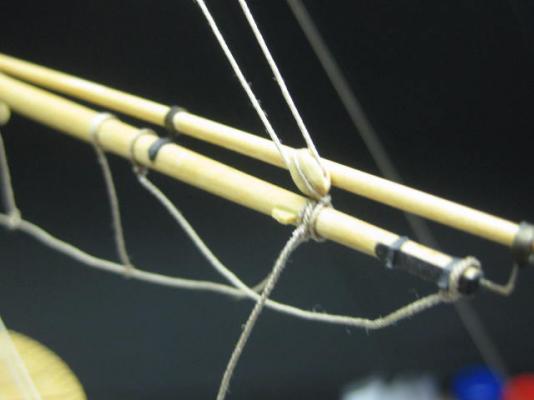
Thanks George, Dave, Greg (that happened and Christian. Robin, I think Druxey explained how they fitted in the post you put up - I don't know any more about them. The Cat came back !!! Below are some pics of the damage caused by Pud on his most recent (and hopefully LAST) excursion through my ship. All damage has been repaired, and wasn't quite as bad as it first appeared. The Crowsfoot Euphroe block lashing was the most difficult piece to repair. The whole repair job took me a full morning, but Pud is still alive and well Danny

-
I don't know, but if you're bored waiting why not tie a few ratlines or something while the stuff does it's job ? Danny
-
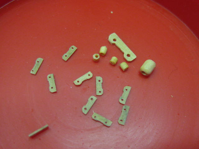
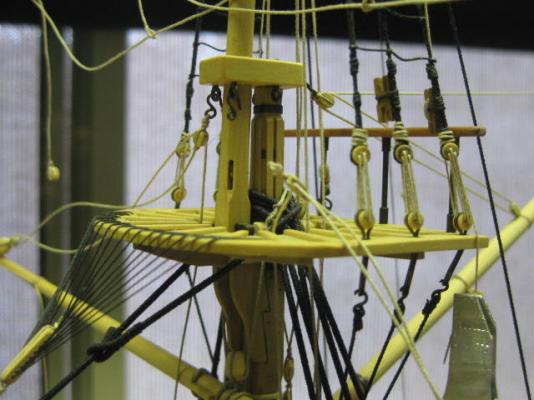
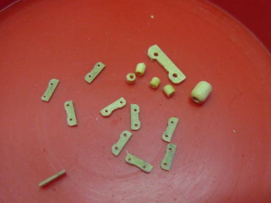
Thanks George and Greg . Topgallant Yard Parrels The topgallant yard parrels are smaller versions of the topsail yard ones. MUCH smaller. Here are some of the pieces with a topgallant yard truck and rib for comparison : The parrel attached to the fore yard ready for crossing the yard : The topgallant yard lift is seized around the end of the yard rather than to the upper block. There is no lower block. The halyard belays to the aftmost cleat on the topsail shrouds : Danny
-
Driver Boom on 6th Rates 1776 ?
Dan Vadas replied to Dan Vadas's topic in Masting, rigging and sails
Hmm, now you mention it so it does regarding the Driver Boom. However no mention was made about the Mizzen Topmast on the plans . Ah well, "Vulture" was a bit experimental in other areas - I'll leave the Mizzen Topmast as is and leave out the Driver Boom. Vulture lasted into the 19th century, so I'll call this the 1792 version . Danny -
Was a Driver fitted to 6th rates in around 1776, or when was it introduced? TFFM is a little puzzling, as it shows a boom on the Masting Plans but no mention is made in the books as far as I've found. I've fitted a Mizzen Topgallant Mast to "Vulture" and a Mizzen Topgallant Yard will also be fitted (same deal as above) - should I now fit a Driver Boom? Danny
-
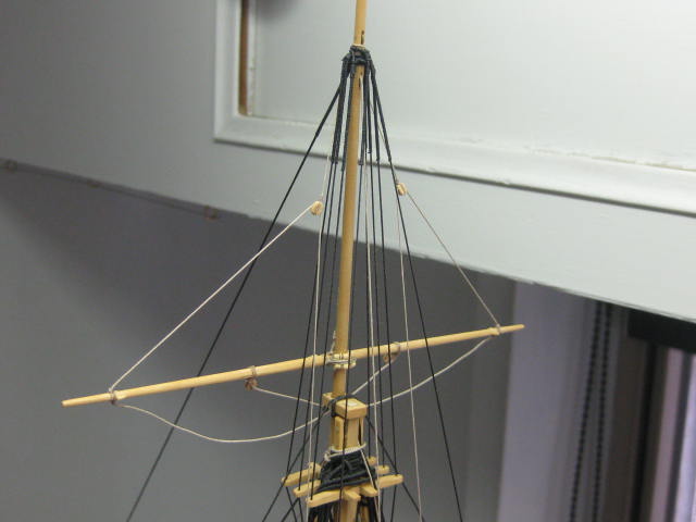
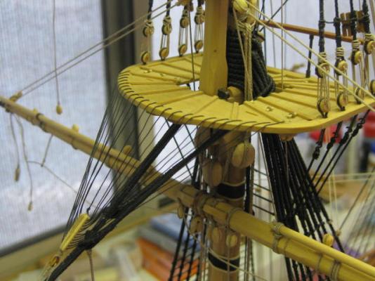
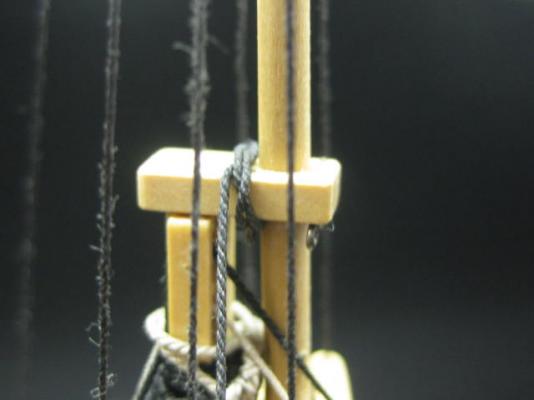
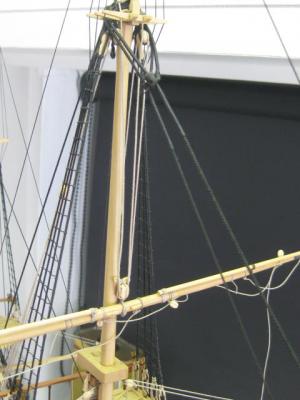
Glad to be of help Tony . Topsail Yard Lifts As with the lower yard lifts these are used to square the yard. They attach a little differently to the lower ones. A Span fitted with a thimble at each end is clove-hitched around the topmast cap : The thimbles at the ends of the span are lashed to thimbles in the standing ends of the lifts : Then the lifts go through the lift blocks on the ends of the yard, up through the lower sheaves of the sister blocks lashed to the shrouds, and belay to the aftmost cleats on the lower part of the shrouds : Danny

-
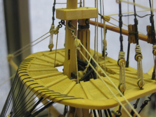
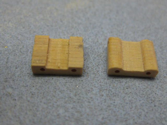
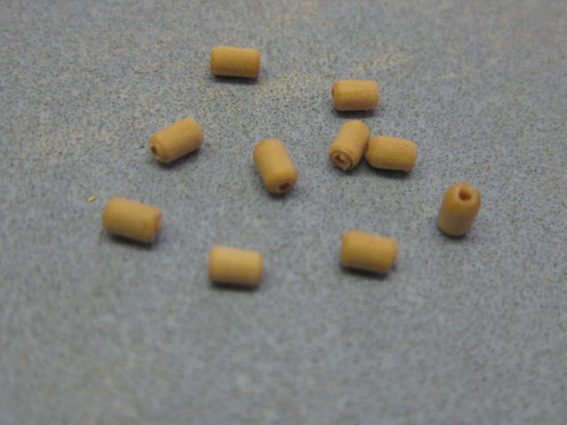
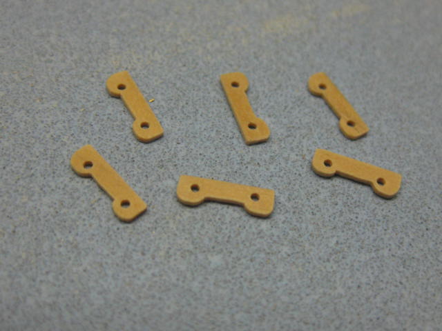
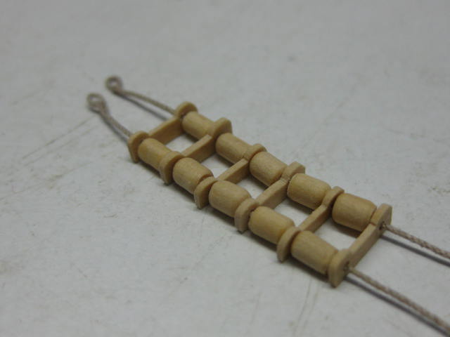
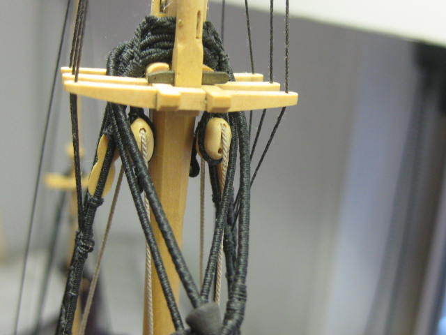
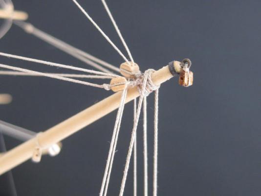
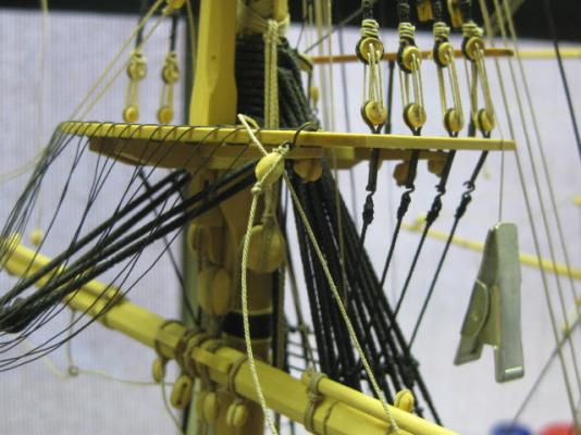
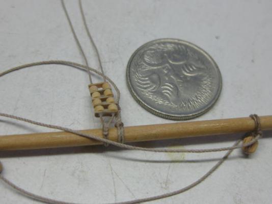
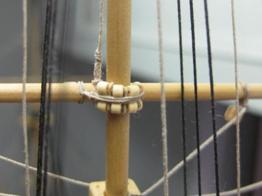
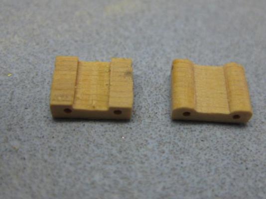
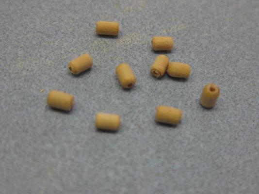
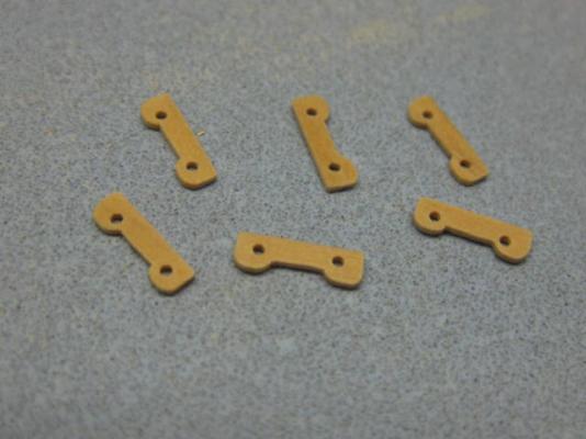
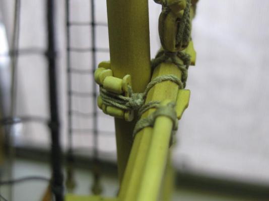
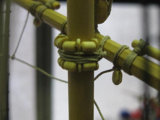
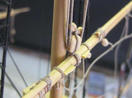
Thanks again for the kind comments George, Grant, Allan, Pat, Greg, Kees and Alex . Parrels The Parrels act as bearings to enable the yard to be raised and lowered more easily. Construction of these starts by PVA gluing together the Ribs in two stacks. This way they can be very accurately drilled and shaped symmetrically. The ones on the right have been finished : Once shaped Isopropyl Alcohol is used to separate the individual pieces : The Trucks are turned on the lathe. They are more barrel shaped than round : Next an eye is "spliced" into one end of two lines, and the ribs and trucks are fed onto them : The two eyes are lashed together around the port side of the yard. The trickiest part of the operation is lashing the lines around the mast. They go over the parrels 3 times and tie around each other. Lots of care needed not to damage anything, like breaking off yards etc : Danny

-
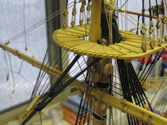
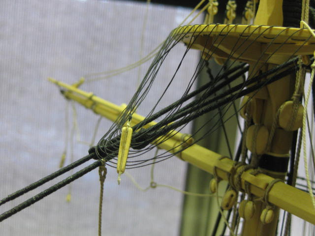
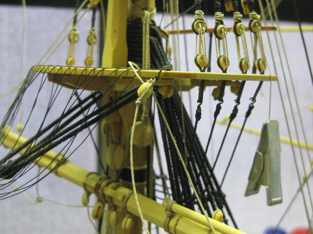
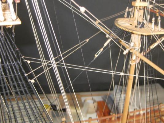
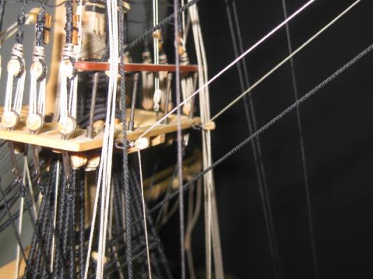
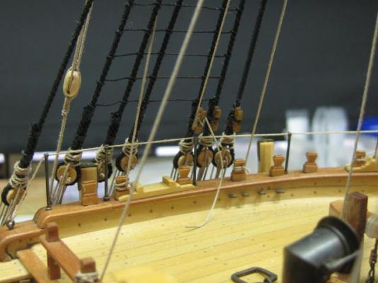
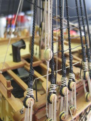
Thanks for the comments once again George, Robin, Mark, Greg, David, Russell, Maury, H, Jihn, Mark and Carl . Robin, I don't have any more pics other than what I have in this build log - sorry. Topsail Yard Tyes Before going into the construction of the Topsail Yard Tyes a warning to others building from TFFM - there is an error in their rigging, pointed out to me by none other than the author David Antscherl. Unfortunately this error was pointed out just as I had completed them . No biggie, I just pulled the whole lot apart and re-did them. At least this gave me an extra couple of days working on the model . TFFM has you rigging the topsail tyes in similar fashion to the lower yards, whereas they use a DOUBLE block on the yard. The standing end of the Tye, one each side, circles the topmast and lashes back to itself via an eye. It then goes through one of the sheaves in the double block on the yard, up to the tye block under the top, and down to a double block for the tackle. The other side does the same. The tye block has two buntline blocks lashed to it's top : An overall view of the tye rigging : The blocks under the top : The double blocks on the ends of the tye falls : The lower end of the tackle has a single block on a pendant which hooks into a ringbolt in the channels on either side. The fall of the tackle belays to a convenient timberhead. This is the main topsail tackle : And the fore one : Danny


-
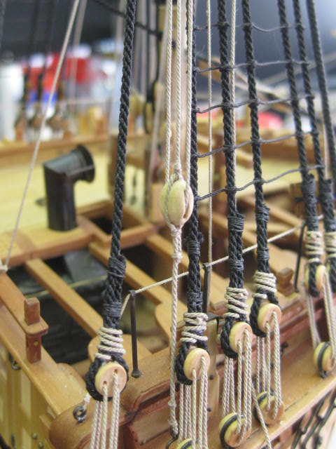
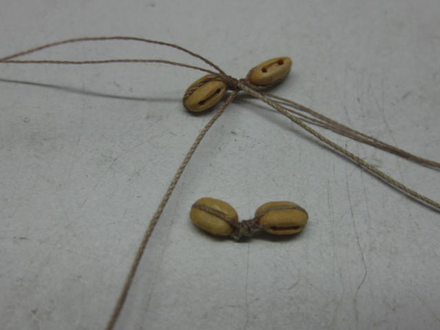
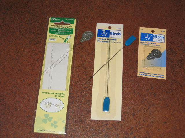
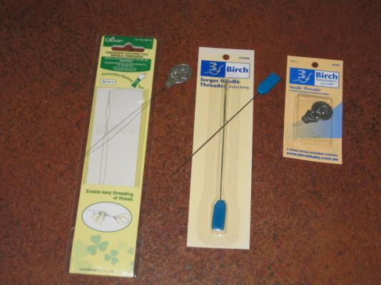
Here's a tip Al. Lash the blocks to the eyebolts on the bench BEFORE you fit them to the deck. Much easier . A needle threader is a great help for tying line through the blocks. There are various types - all work very well. The ones with the thicker wire and the one with the long wire are particularly useful when rigging around the bottom of the mast or under the mast tops : Danny
- 265 replies
-
- 2
-
-
- finished
- artesania latina
- (and 1 more)
-
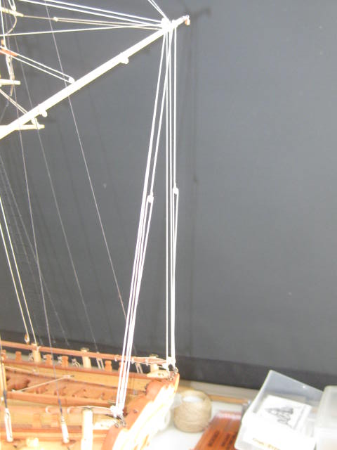
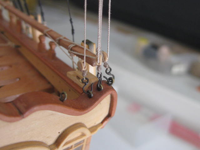
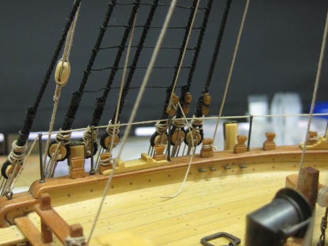
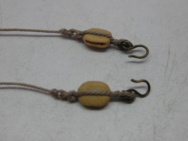
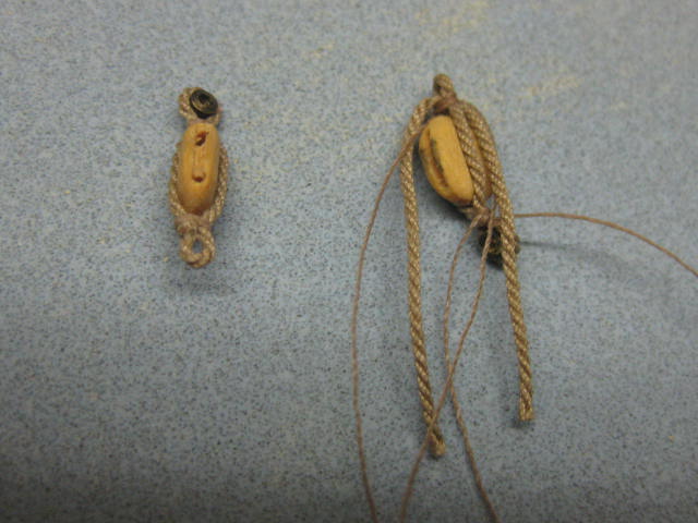
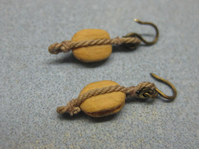
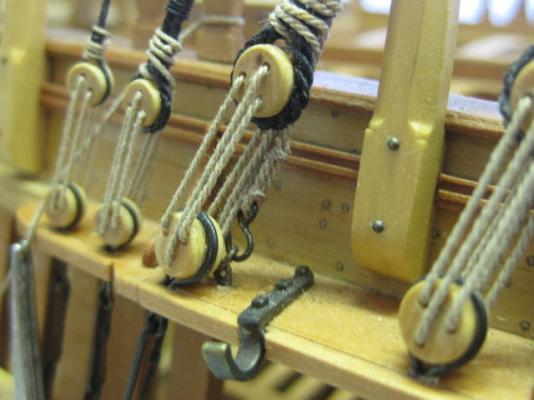
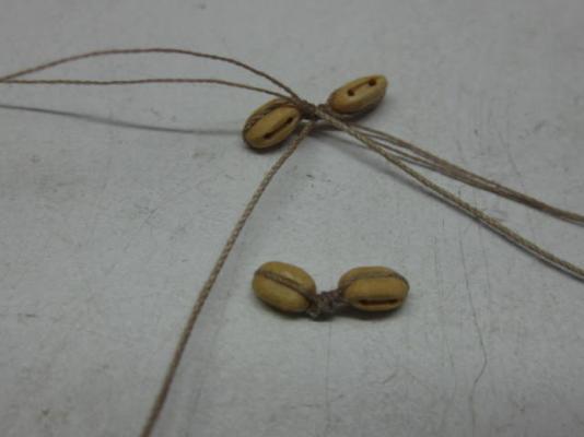
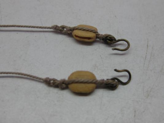
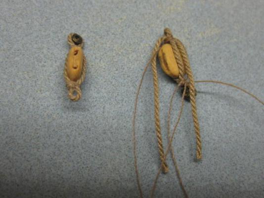
Thanks for the replies guys . Main Stay Tackles These are used when loading into the hold, and also for launching the cutter. There is one above each hatch. The lines will tighten later when the hooks are attached to the cutter : They consist of a double and a single block on each. The lower single block has a thimble and eye seized into it. A large hook goes through the thimble : The standing end of the pendant lashed to the stay : Danny


-
Damn, and other expletives . Good luck with the repair. I have some of Chuck's hooks too, but decided against using them - they were a bit too small for my scale in any case. I had the feeling they could be a bit vulnerable. Danny
- 517 replies
-
- 1
-
-
- Endeavour
- Artesania Latina
- (and 1 more)
-
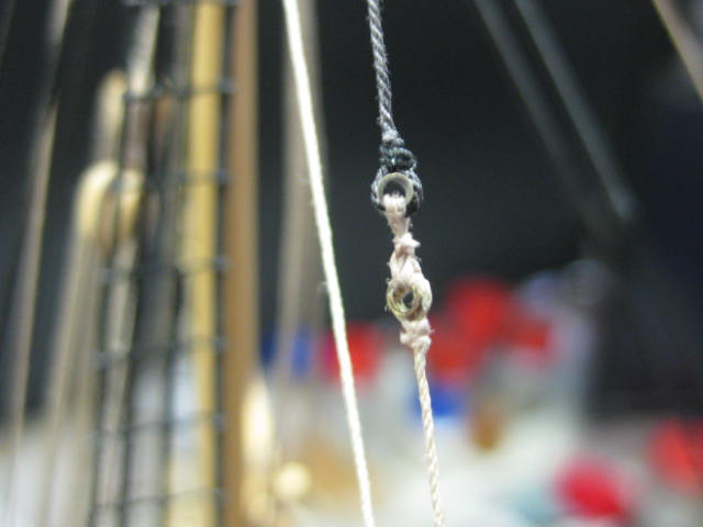
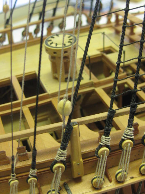
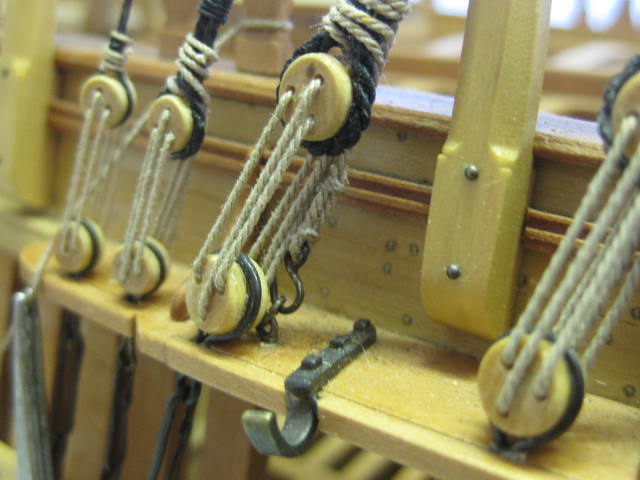
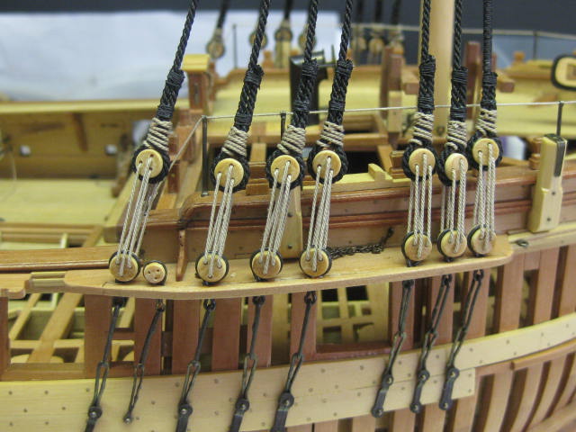
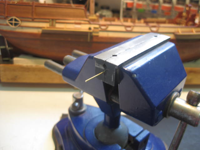
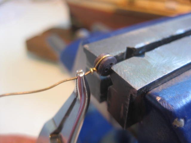
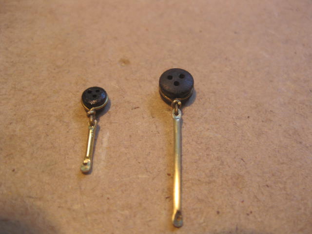
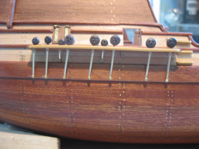
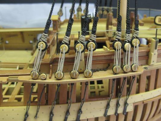
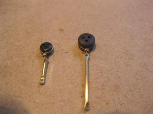
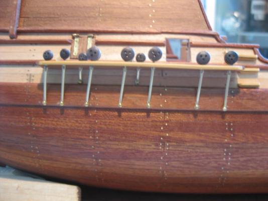
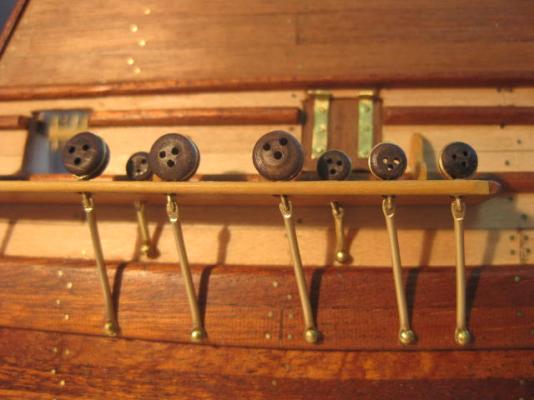
Hi Al, I think I also used 1.2mm rod. If you heat the end of the rod to red hot over a gas flame and then let it cool without quenching it will soften the brass enough to make it more workable. The wire I used was already a "soft" type. One point - make sure the centre hole in the deadeye is to the bottom. You have it upside-down, but it will probably turn in the wire with a bit of persuasion. The centre hole in the upper deadeye will go to the top. Danny
-
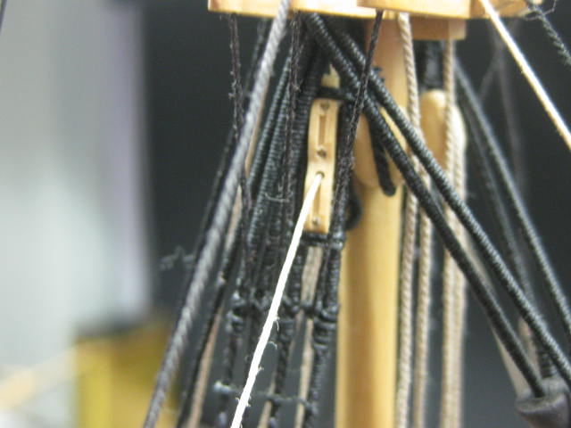
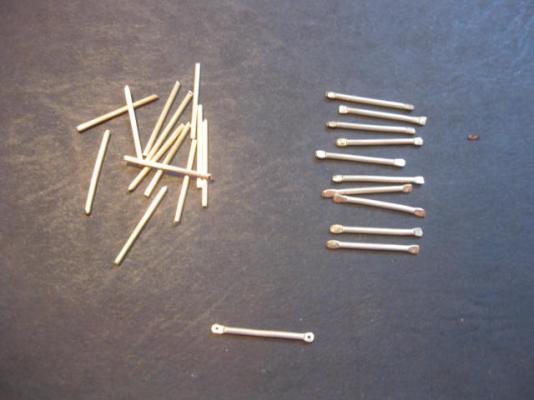
Hi Al, I just went back through my computer and found my method of making the Chains on HMS Supply - a bit different to the way I remembered them, but neat nonetheless . Here are some pics to show you how they worked : I flattened the ends of the chains by squeezing them in my vise : Aligning the Chains with the mast top : The finished articles : The holes in the Channels only need to be large enough to slip the chain itself through. Danny


- 265 replies
-
- 2
-
-
- finished
- artesania latina
- (and 1 more)