Dan Vadas
-
Posts
3,261 -
Joined
-
Last visited
Content Type
Profiles
Forums
Gallery
Events
Everything posted by Dan Vadas
-
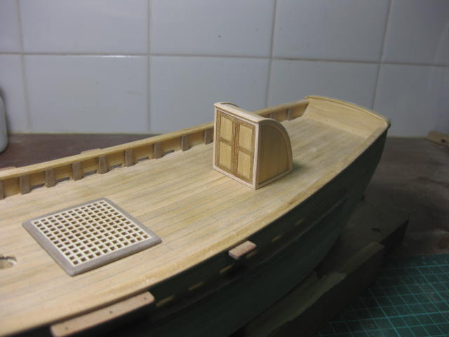
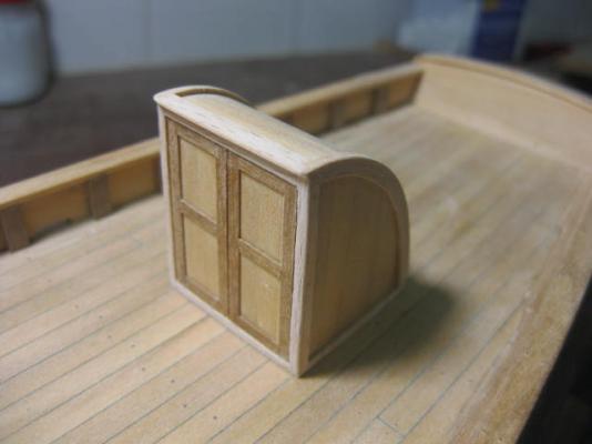
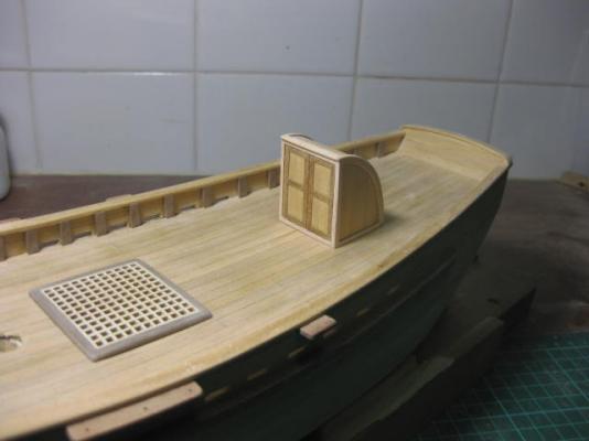
I've finished the Companionway ready for lacquering - the hinges and handle will be added later. I've "done my own thing" with the trims - I thought the kit's were a bit overscale in that department. I've scaled the trims down to 3" x 1" - the kit had them at about 5" wide which would have been way too big. The planks are 7" wide, same as used on the deck. I used cut-down kit supplied Birch for the trims. For the door frames I used some light coloured Walnut I had left over from another kit. I made these a scale 1/2" thick, as the door planks would have been rebated in from the back. I've also treenailed all the trim, but they won't show up until after lacquering. The companionway looks WAY too big on the boat, but the crew would have to duck their heads getting down it - it gives a sense of how small this boat was . I've also sanded the grating surround flush with the grating.
- 147 replies
-
- 1
-

-
- norfolk
- modellers shipyard
- (and 1 more)
-
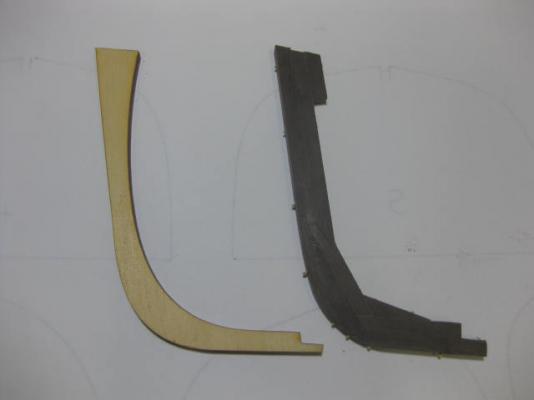
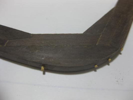
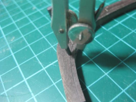
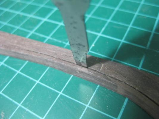
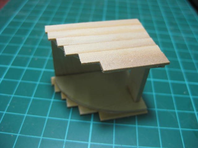
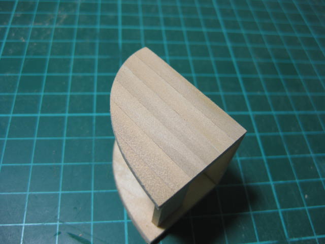
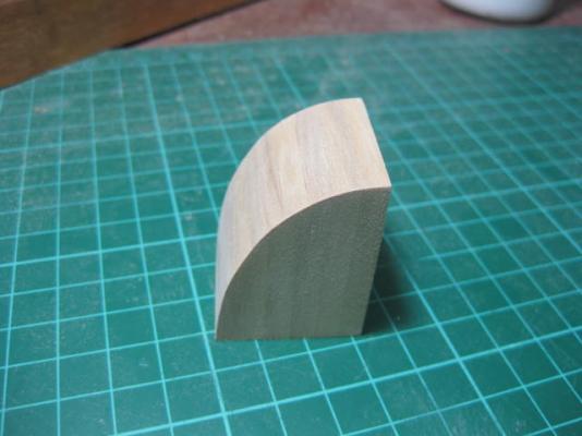
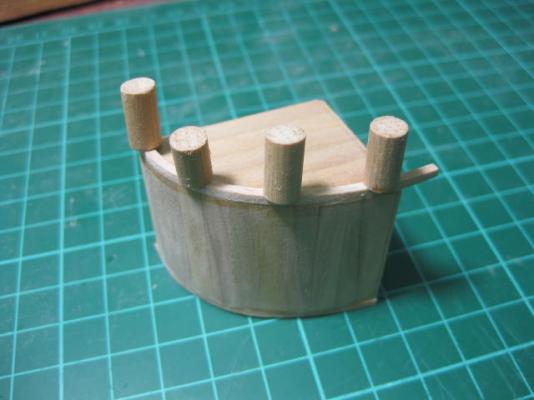
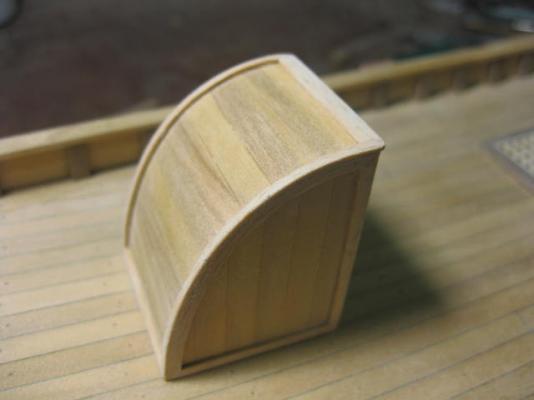
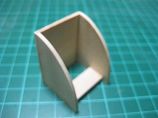
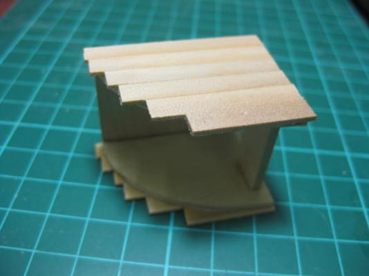
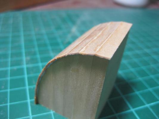
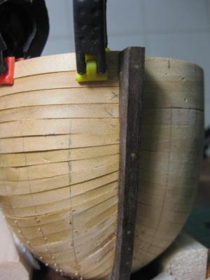
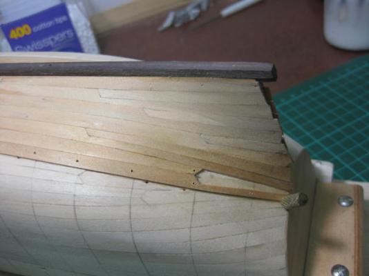
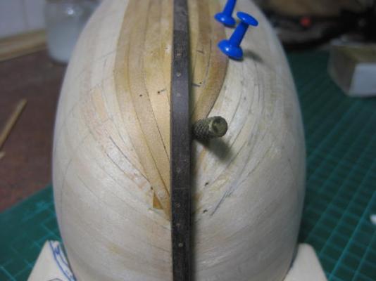
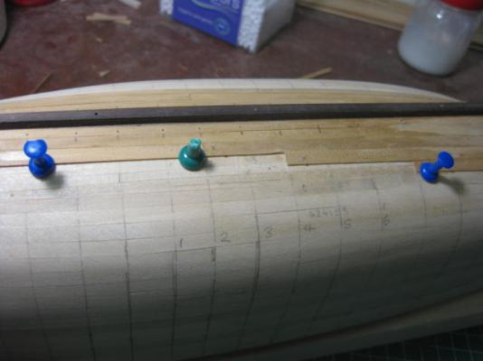
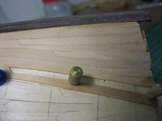
The Companionway The kit supplies three ply pieces to make up the base for the companionway. I added a fourth - the brace at the rear .... it needed something to hold it firmly together while I worked on the rest of it (pic 1). I planked the sides (I'm using Norfolk Pine instead of the kit planks to keep it in "theme"), leaving a fair bit of overhang. When they were dry I sanded them to the shape of the sides, and also sanded the faces (pics 2 and 3). Then I planked the curved roof/back section, again leaving a bit of overlap which I'll sand back tomorrow.

-
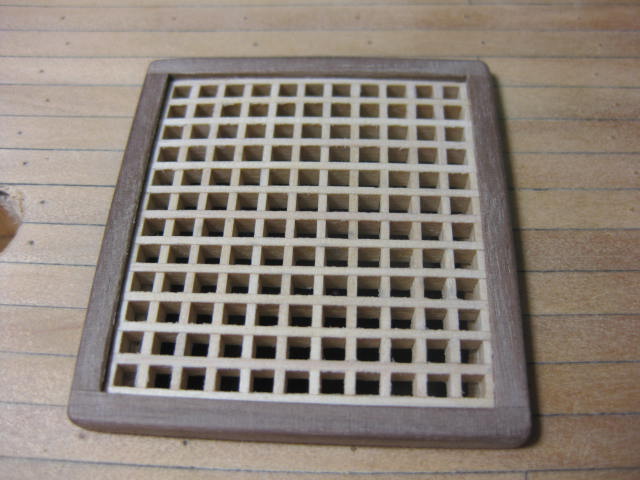
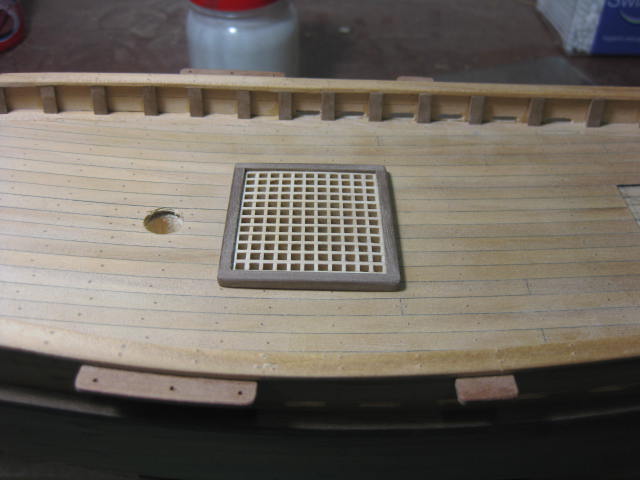
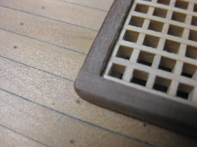
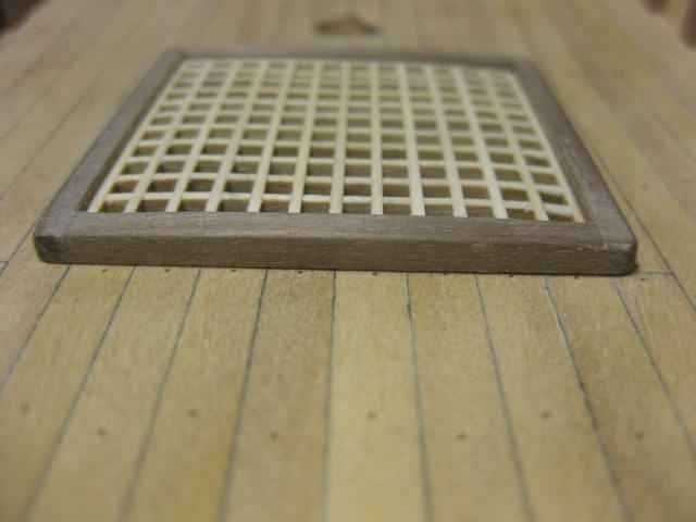
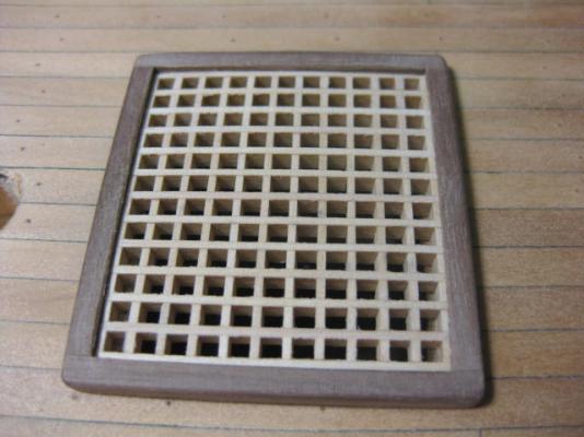
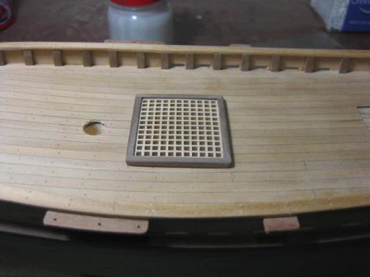
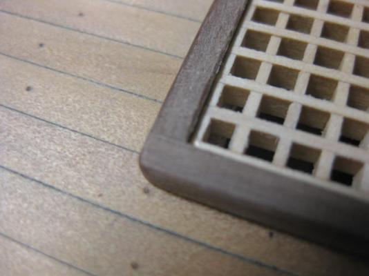
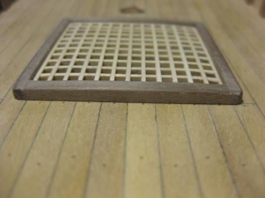
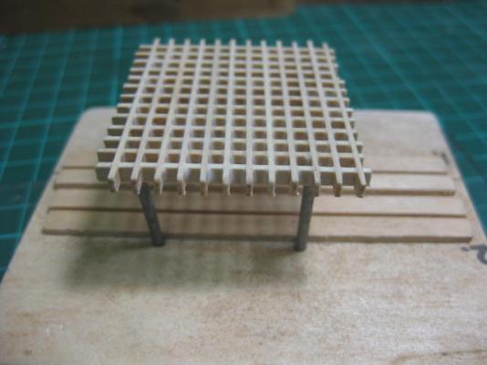
Grating and Surround I've finished off the Hatch Grating. It's only a dry fit so far as I will need to sand the deck a couple of times between coats of lacquer, but I wanted to fit it now so that I didn't need to trim out the hole in the planks later. For those who haven't made a grating and surrounds I'll go through the sequence I use (the rest of you can just look at the pictures ). 1. Assemble and glue the grating as I described a page or two ago. Note - I use 120 grit Aluminium Oxide paper glued to a cork block for the heavy sanding, and 240 grit glued to a sanding stick for the preliminary finishing work. You can't get neat square joins by just using sandpaper held by fingers. 2. Sand the excess material from all four sides of the grating, leaving a full batten all around. If this makes your hatch slightly larger or smaller than the plans then so be it - it's usually only a matter of about 1 - 1.5mm. 3. Sand the BOTTOM of the grating flat to take off any high spots caused by uneven material. If your deck has a camber (mine doesn't) then you need to sand the camber into the bottom to get a good fit. 4. Sand a camber into the TOP of the grating. This camber should be about 1.5 scale inches more than the camber in your deck. (see pic 4) Another note - I'm only making a simplified version of the surround on this model, as nothing is visible through the grating at all. If I were to make a removed or half grating surround I would have made it with the correct rebates. 5. Cut two athwartships lengths of the surround, making them about 2mm longer than the grating. Sand one end perfectly square - a disc sander is best for this job - leaving about 0.5mm overhang at the unfinished end. 6. Placing the grating on a piece of glass (for ease of removal) carefully run a bead of PVA onto the edge of the grating and also the first piece of surround with a small paintbrush. Line the sanded end of the surround up with one corner, using a piece of scrap on the adjacent edge to ensure perfect alignment. 7. Do the same with the opposite surround, aligning the sanded end on the same as the previous (e.g. BOTH Port ends). Let these two surround pieces dry for at least 15 minutes. 8. While the glue is drying cut the other two lengths of surround - make them about 2mm longer than the finished length. 9. Go back to the first two surround pieces and sand the excess flush with the grating using a sanding stick or cork block. Also sand the deck camber into the bottom to match the grating (if your deck has a camber). Check for fit on the deck and re-sand as necessary. 10. Now glue the other two pieces to the grating, leaving a little protruding from each end. Let the assembly dry for at least 15 minutes again. 11. When dry, sand the ends of the longitudinal surrounds flush with the outsides of the athwartships ones. 12. Now sand the surrounds parallel with the top of the grating, ensuring you follow the camber. The surrounds should finish slightly higher than the grating. 13. Round off all four corners, and sand a round along the outside of the surround. 14. Finish off the surrounds with fine (360 grit) paper. You should finish up with something like the one in the pics below. Last tip - if you have multiple gratings to make then do each step above for them all at the same time (if possible). This saves a lot of time waiting for glue to dry - you can be preparing the next couple while waiting for the first etc.
-
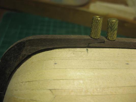
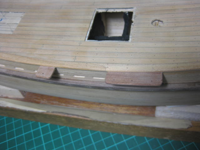
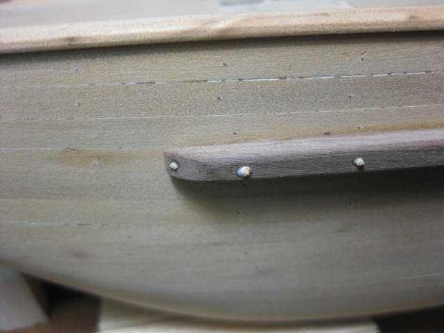
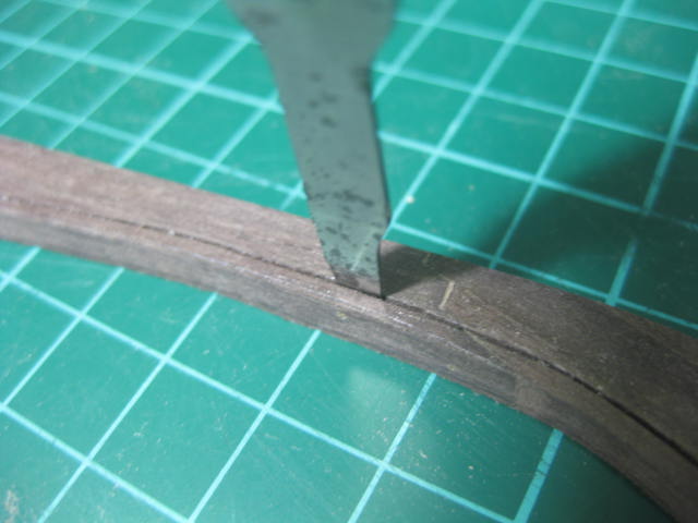
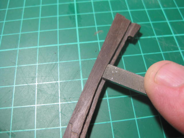
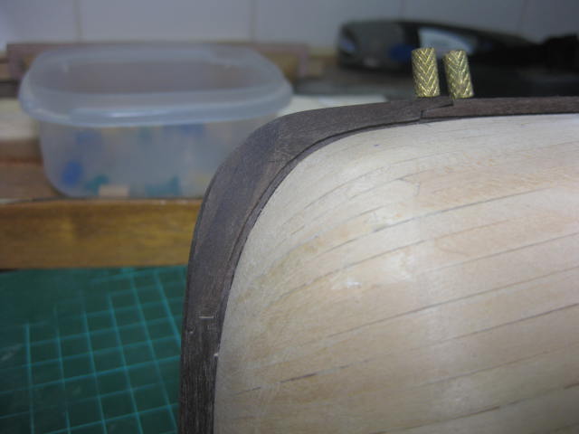
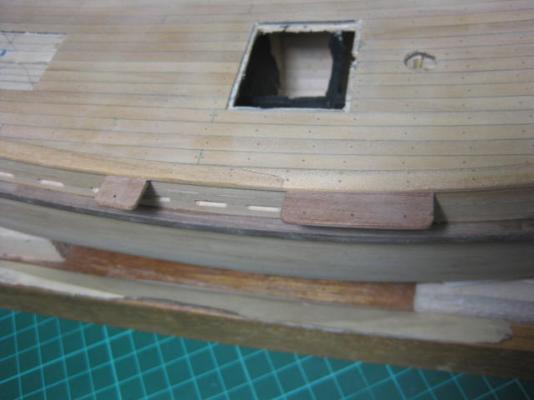
Take two on the channels - I decided they were too wide and narrowed them by nearly half. There is no railing behind the shrouds to interfere with them, but their IS one behind the backstay so I won't drill the hole for it until just before I fit the backstay. I was pleasantly surprised by how strongly the channels are attached - I'd pinned them with brass wire and epoxied them on. I trimmed them with a razor saw, and they didn't even look like coming adrift .

-
Channels In another departure from the kit I've fitted Channels for the shrouds and backstays as on the Replica. I'm not too sure about their width yet - I may narrow them a couple of millimetres after I have the mast fitted and can get a better idea of the angles of the shrouds.
-
In trying to come up with a reasonable explanation for the variety of timber I'm using to build this model, not JUST with Norfolk Island Pine, I've come up with the following : First - it was soon discovered not long after the 1st landing in 1788 that the Norfolk Island Pine was not a suitable timber for ship building, with the possible exception of planking - the timber had far too many knots in it to make it a structural material. This would have been a major disappointment, as the British Admiralty was counting on the timber (as described by Cook) for use in making masts etc, their supplies in the Baltic being uncertain at the best of times. This boat was launched in 1798. I figure 3 to 4 years for her construction, given the shortage of man-power and tools etc necessary. That brings us back to around 1794 for a start on the actual work. "HMS Sirius" was wrecked on 19th of March 1790 in what was then known as Sydney Bay, Norfolk Island, only a couple of hundred metres from where the "Norfolk Sloop" was built and launched. It's a known fact, and perfectly sensible, that everything that could be salvaged from the wreck was carried ashore in the next year before she broke up altogether. A lot of the timbers would have washed ashore in any case as they came loose - the prevailing winds and tide would have seen to that. Remember this was a fledgling Colony - most of the persons on the island were busy enough trying to survive. Anything of use from the wreck would have been utilized. There was a dire need for sea transport, both on Norfolk and at Port Jackson (Sydney) as shown by Governor Arthur Phillip's urgent request to England at the first opportunity for a Cutter or Schooner to be shipped out. To that end the idea of building a boat on Norfolk would have arisen almost immediately after the wreck of Sirius, and whatever timbers and fittings they could salvage would have been put aside for the task. Pieces like Deck Frames for the gunwales, keel and rudder, a couple of Yards for the mast, jib and boom - right down to things like blocks, deadeyes and nails would have come from Sirius. This is pure conjecture on my part, but I think it's quite plausible (and probable). Anyone with CONCRETE information to the contrary can feel free to tear my theory to shreds. (I can already see Jim Lad, Blue Ensign and Neptune with their fingers poised over their keyboards ).
- 147 replies
-
- 1
-
-
- norfolk
- modellers shipyard
- (and 1 more)
-
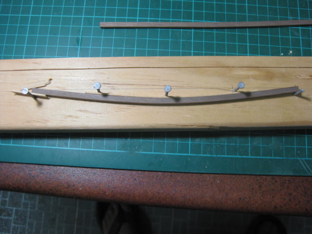
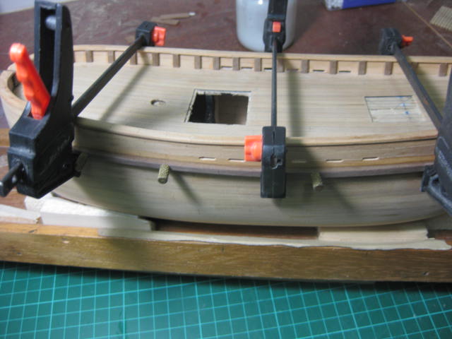
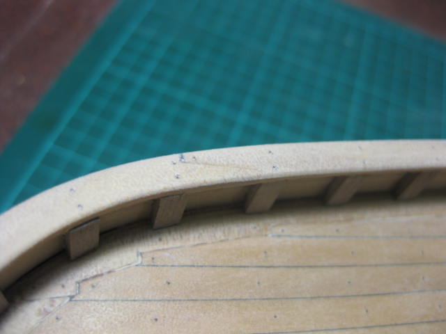
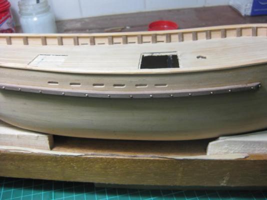
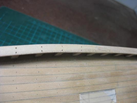
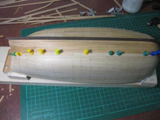
Gunwales I've made and fitted the two Gunwales from 4mm x 4mm walnut strip as supplied in the kit. To get the sheer (upward) curve into them I followed kit instructions and soaked them for 15 minutes. I then placed them in a simple jig made from a piece of timber and 5 nails, placing a piece of scrap timber on each nail to avoid denting the strip, and let them dry overnight in the jig. To follow the curve in the hull I clamped them from one side to the other and used 0.8mm planking pins to keep the height correct. I've treenailed the gunwales for extra strength (another 30).


-
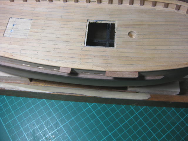
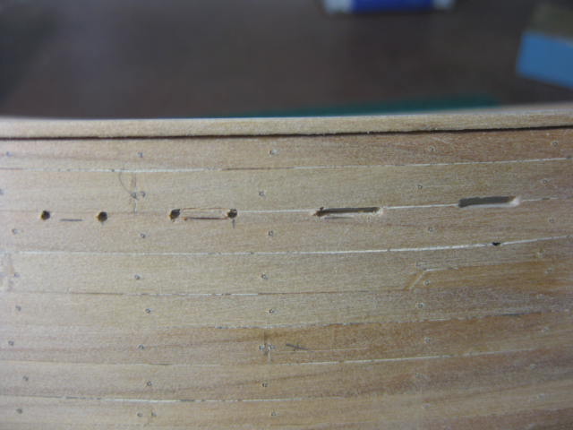
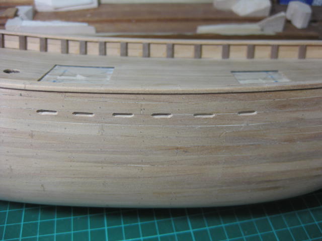
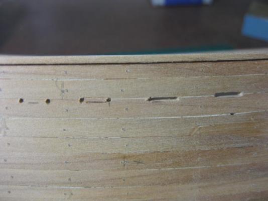
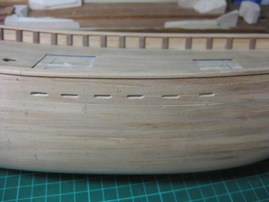
Scuppers I've cut in six Scuppers on each side. These are not a "fun" job to do - very fiddly to get them all at the right height and looking even. I started by marking them down from the cap rail 0.6mm up from deck level, drilled a 1.2mm hole in each end and cut them into an 11mm slot with a knife. I tidied them up with a couple of small needle files.
-
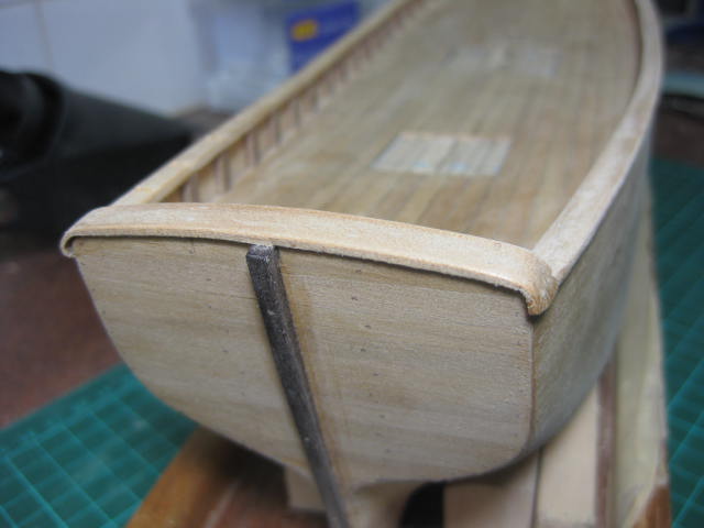
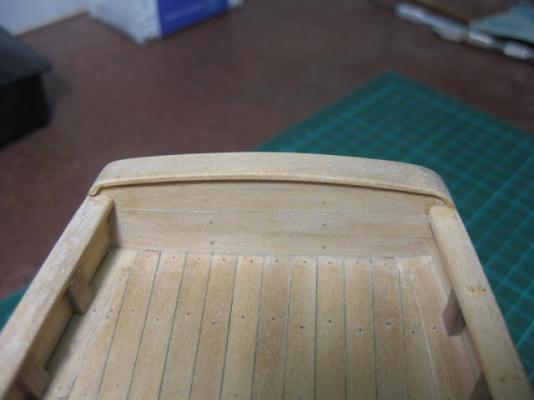
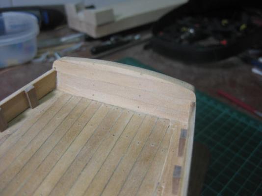
I've treenailed the cap rails (102 MORE nails) and fitted a cap rail to the transom. The kit had a straight transom fitted with a piece of walnut, but I've rounded it off the same as the Replica and fitted a Norfolk Pine cap rail to match the others. I managed to get a 5mm radius bend in each end by soaking in cold water for 10 minutes and bending both ends with a small pair of rounded needle-nose pliers. I then set it into a simple jig made from a piece of scrap ply with the appropriate radii cut into it, placed it on a piece of balsa and held the cap rail with half a dozen nails pushed into the balsa. I let it dry overnight before fitting it. This may not be the greatest modelling timber to use, but it sure can take a tight bend .

-
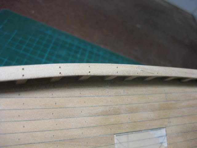
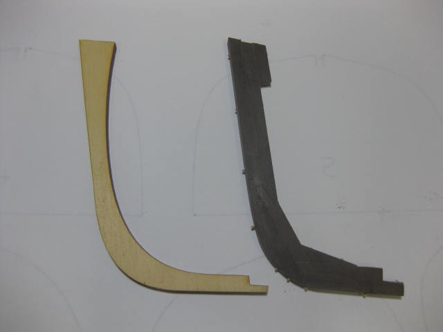
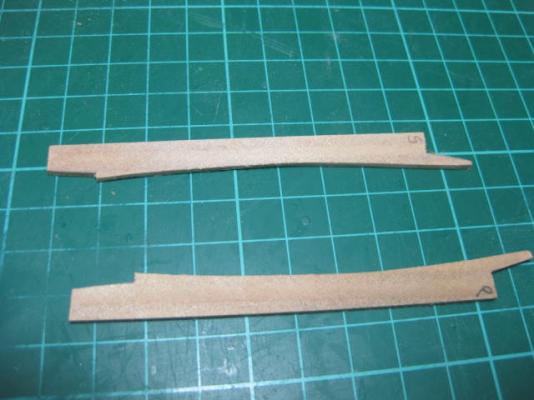
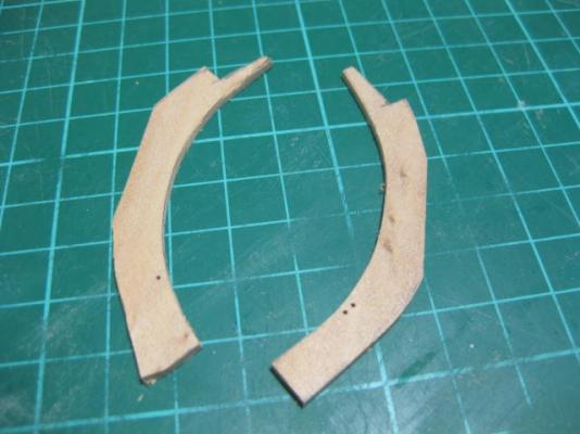
Cap Rails I've made and fitted the Cap Rails to the bulwarks. I scratch-built these from Norfolk Pine instead of doing them by the kit instructions, which said to do them in two narrower pieces to make bending easier. I cut a few wider pieces and shaped the INSIDE edges to fit on top of the "frame" edges. I scarfed the joints. I didn't worry about shaping the OUTSIDE edges - I just made sure I had sufficient material to leave a 1mm overhang, and I sanded that edge to shape after I glued them on. In the pics you can see the "before" (port) and "after" (starboard) results. I've also drilled the starboard rail for treenails.

-
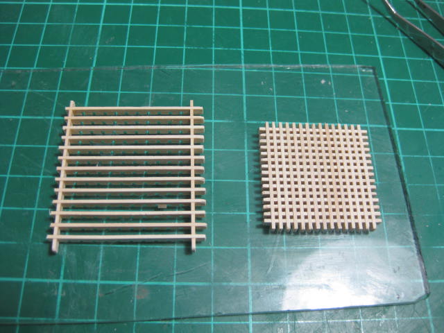
Grating I've glued together the Grating. The kit supplied one was a very nice piece of pre-assembled material, but it was too small in scale - 1mm (unusual for a kit - they're usually too BIG). I used 2mm pre-cut grating strips - these scale out to a 3" hole, although the grating material itself is a touch thin at 1.5mm. My method of making gratings : I do all the assembly on a piece of glass - it's easy to get back off if glue runs down the strips. First I use a drop of full-strength PVA to glue each corner together. I let that set for 5 minutes, then I lay all the strips one way with a drop of PVA at each end only. I turn the grating over and lay the rest of the strips, gluing them the same way. Then I give the whole grating a very liberal wash with diluted PVA (75% water) and blow out as much excess from the holes as possible. I support the grating on three nails stuck into a piece of balsa and let it dry thoroughly. Later on I'll sand the bottom to remove any glue that has run down, and sand the top into a camber. Then I'll trim the edges and make the surrounds.

-
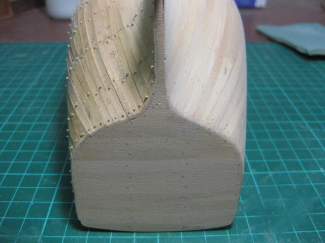
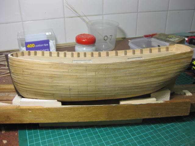
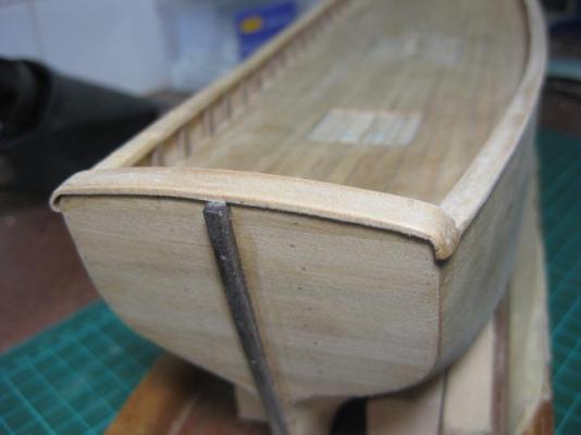
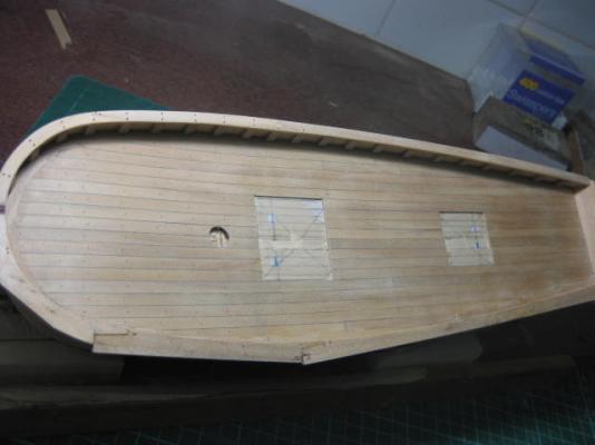
I've blocked down one side and the transom. It took about 1 1/2 hours to get this far. There's still a touch more sanding needed which I'll do just before lacquering. The treenails have all but disappeared - I'm hoping they come back later . Preliminary sanding of the hull is all finished. I'm pretty happy with the result - I didn't manage to cut through any of the 0.5mm planks (although I think I came pretty close on a few ). I've fitted the stern post. The kit plans don't call for one, but ship's longboats had them and as Norfolk is built similarly I added one.


-
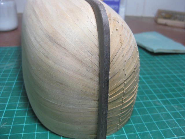
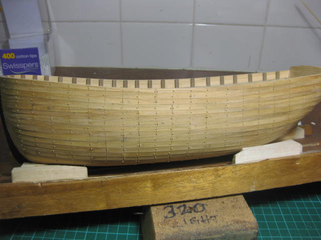
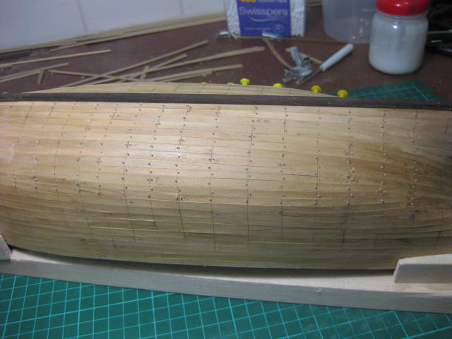
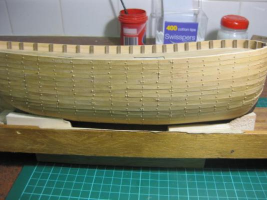
Treenailing Hull Ho Hum ..... more treenails. I have the Port side finished, also the Transom. There are 1,760 in the hull and deck to be roughly precise . It took me about 25 hours including marking, drilling, and drawing the bamboo. And I just put the last one in . Now for some serious hull sanding.

-
Another milestone - the last of the 2nd planks has been fitted . Now there's just the small matter of a couple of thousand more treenails and I'll be able to sand the planking into something that looks a little less like a dog's dinner.

-
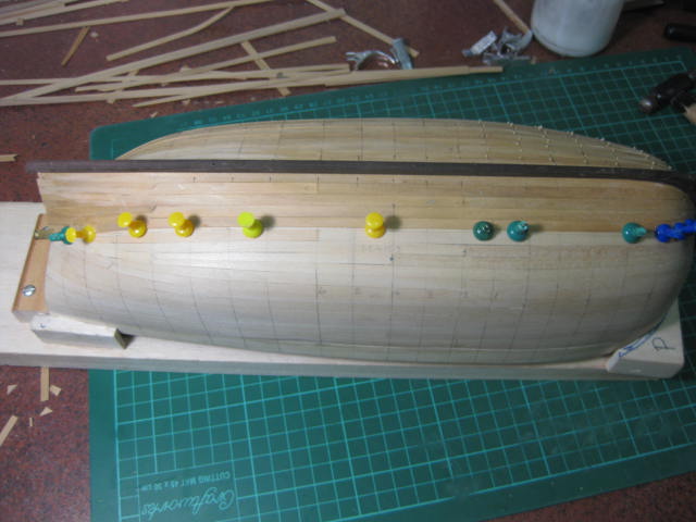
Cranking on - 5 runs of planks done on the Port side. It's SO much easier the 2nd time around when you have the other side to measure from . Another 2nd Planking Update. I'm at the halfway point on the Starboard side - these ones are running a lot better than the Port side. I guess I was OVERTHINKING a bit on the port side and added too many drop planks in the bow - there are NONE on the starboard side, but each plank is still finishing exactly in line with it's opposite number (go figure). I only needed three at the stern as well. To fill in time while waiting for planks to dry I've been treenailing the port side - I'm over half way with them. That saves a fair bit of tedious work later on if I'd been doing them all in one go .
-
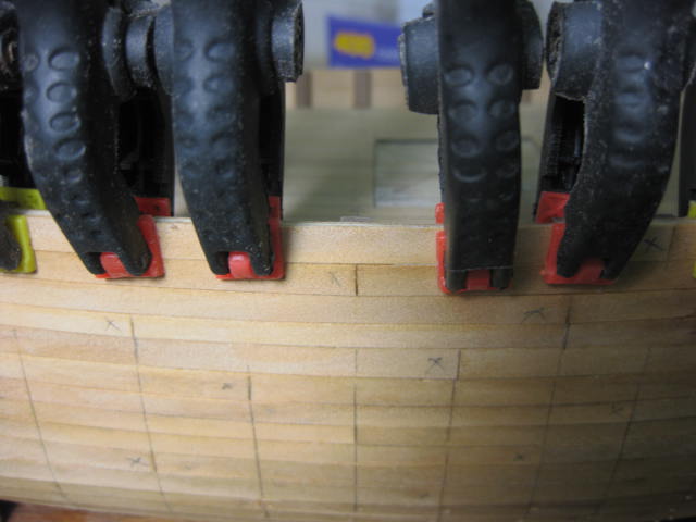
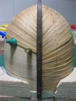
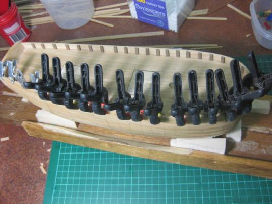
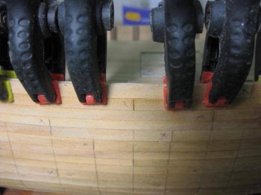
I've laid the last plank on the starboard side. The top few needed a fair bit of lateral bending to follow the sheer, so plenty of clamps were needed. It looks a bit like a scene from a 50's Horror film - "Attack of the Giant Cockroaches" .
- 147 replies
-
- 1
-
-
- norfolk
- modellers shipyard
- (and 1 more)
-
Making Treenails I'm a bit of a novice as far as drawing bamboo treenails goes, but I'm having success at doing them - thanks to Kim (krt2) who gave me a good tip. I use plain old bamboo BBQ skewers - about $2.00 a pack of 50 or so at the supermarket. They are about 250mm long. I use them dry. First you have to split the skewers into as many pieces as you can - I can get about 7 or 8 useable pieces out of each one. Use a VERY sharp Xacto blade. I use a digital caliper to check that the minimum size of each piece is pretty close to my finished diameter - a couple of hundreths of a mm under don't really matter. Any that are way too small go in the bin. This is the trick - when you see the Byrnes Drawplate you immediately assume that you put the end of the sliver into the BIG side of the hole - WRONG. You feed it through from the SMALL side - that's the way the cutter works (that was Kim's tip). Start off in the biggest hole, pulling it through. If it seems like you can go down a few holes, do so BUT be careful of bamboo splinters - I use a pair of small pliers to pull the bamboo through with. I did get one splinter in my finger when I got a bit slack - they are VERY hard to get out, a bit like trying to extract a glass splinter because they are so tiny. Work your way through the holes until you get to your desired diameter. A lot of the holes decrease by 0.002" instead of 0.001" - pull it through the larger one a couple of times before going down to the next size. That's about it - with a bit of practice you should be able to pull a good length (about 220mm) in a bit over a minute. You'll lose a bit where the pliers crush the end - just snip it off to give you a good start on the next hole.
-
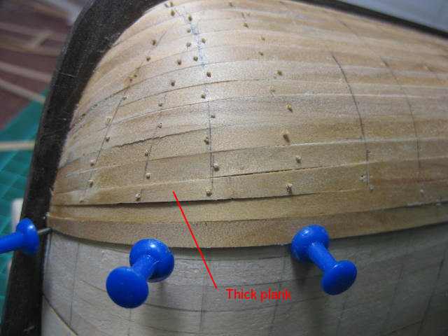
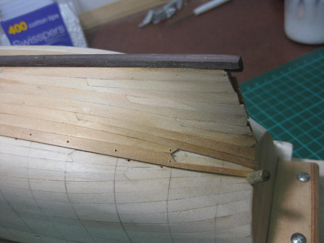
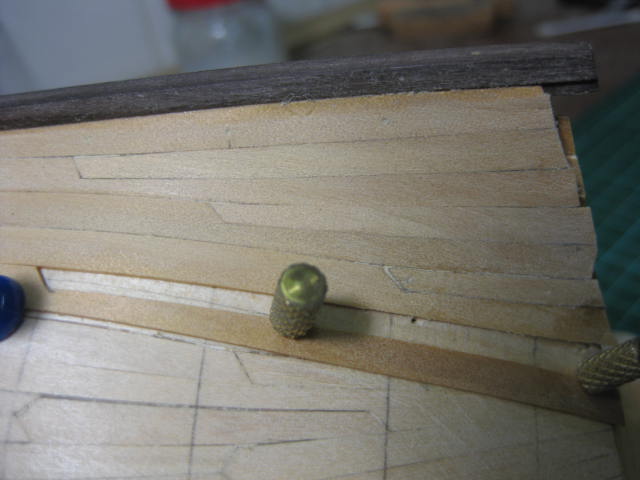
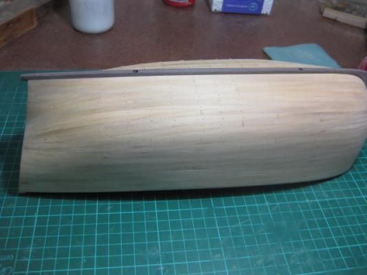
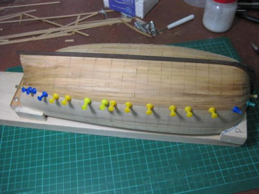
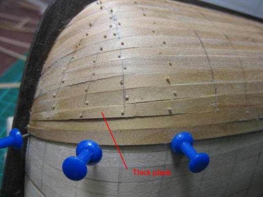
Planking Update. I'm about 2/3 finished on the Starboard side. Pic 2 shows the bow section - I've deliberately taken this pic in a bad light with shadows showing how far out some of the 0.5mm planks are .... or SEEM to be. They are actually spot-on, just that some are very slightly thicker than others (one especially). Any new builders who get to this stage and think they haven't done it properly - don't worry. As long as each plank is firmly against a well-faired base planking it'll be fine when it's sanded flat. The pic of the stern planking shows I still need to do a little bit of work to get the next plank or two to run properly - no problem.
-
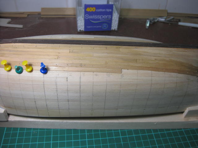
A progress update on my 2nd planking. Now that I've done the "fix" on those couple of errant planks it's all falling into place beautifully . I'm about 1/3 of the way "up" the starboard side. The bow planks are curving in nicely, and I'm up to the first drop plank in the stern area. I'm using a 5 butt shift on this one, although the only butt joins (apart from stealers and drop planks) are over 6 frames in the midships section .... remember, this boat is only 38 feet long. I've used a pattern of 1-5-3-6-2-4 which happens to be the "firing order" of a six cylinder Holden engine, something I've never forgotten since my wasted youth .


-
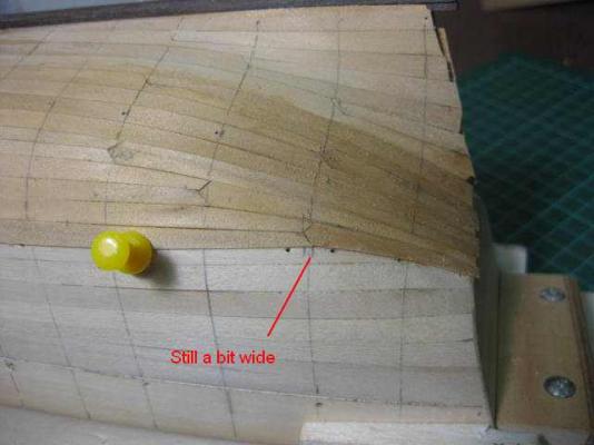
To prove that I can stuff up planking just as well as anybody else .... I've ripped out the last three planks in the Bow section, and am re-doing them. They were pointing toward the deck far too much at the stem, and not getting any better the further I went. I'd have needed at least 5 Drop Planks to correct it - if I could have caught it at all . The problem started with the 1st plank I laid next to the Garboard Strake. I guess I'm too used to working from the deck down - I was tapering the wrong edge of the planks, and didn't taper this one enough anyway. I'll finish off these couple, turn the ship the right way up, and start from the top of the Bulwarks. This will have the added advantage of not needing as many pins in the bow area, as the planks will want to lay naturally in the rabbet (I hope). I'll be able to taper my planks a lot more accurately too - at the moment I'm just guessing. The planks on the right in Pic 1 have been removed, and I've re-tapered the first and re-fitted the second one. You can see how far out I was getting by the way the planks on the left of pic DON'T follow the 1st planking. At least the stern area is coming out right on target (Pic 3). I've added four Stealers so far. As the hull transitions to a convex curve I'll need a Drop Plank or two.
-
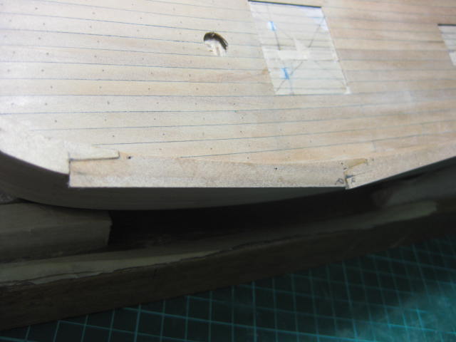
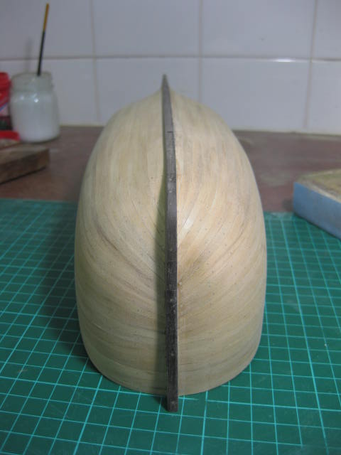
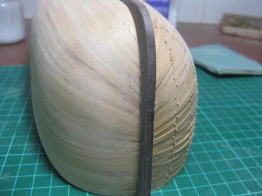
Garboard Strakes I think I'll do the 2nd planking from keel to deck, the reverse to the 1st planking, to figure out which way is better. Because I did the 1st planking fairly accurately I have some good lines to follow, and shouldn't need to do any re-measuring and calculating. I've fitted the Garboard Strakes to both sides, and for good measure also the forward parts of the next strake. I don't know why I've taken so long (in models) to cut a rabbet into the stem and keel - it makes life so much easier .... just slide it into the groove . No more pins or clamps needed other than a couple along the length of the plank. BTW - the pic of the bow ... both ends of the garboard, and the 2nd strake, are exactly in line. The shadow in the pic makes one look longer than the other.
-
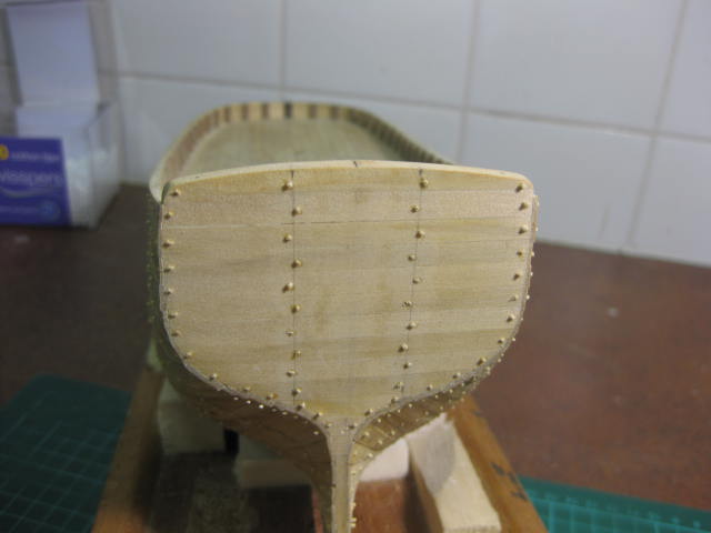
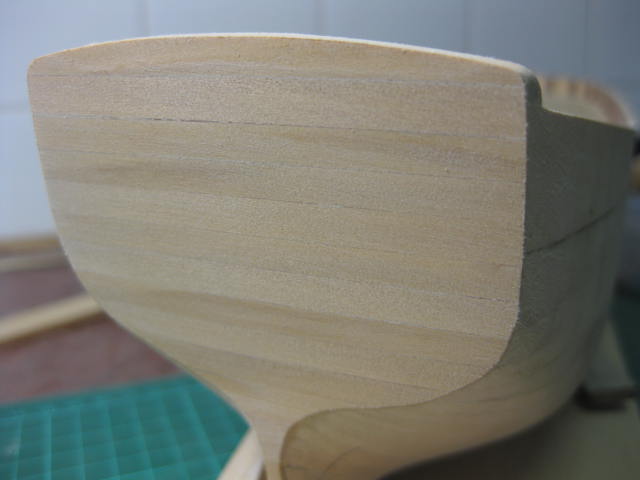
Hull 2nd Planking I've planked the Transom.

-
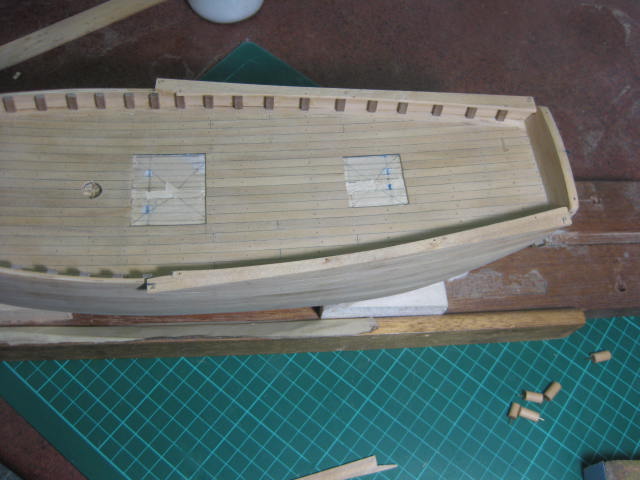
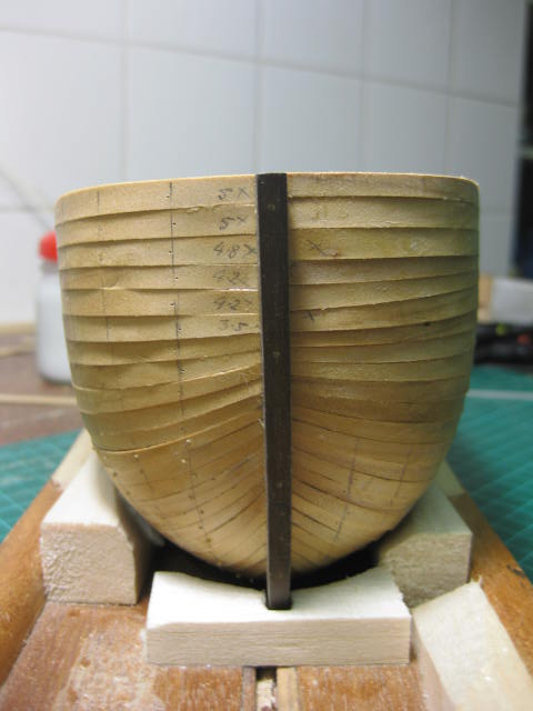
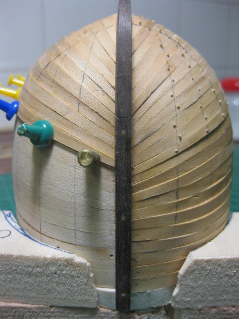
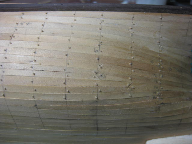
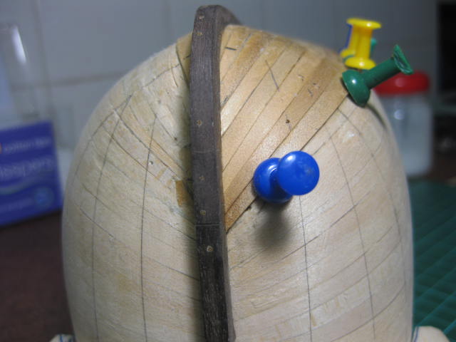
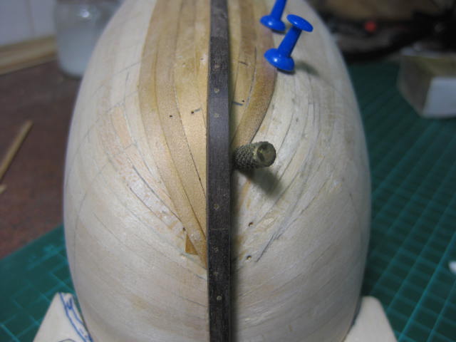
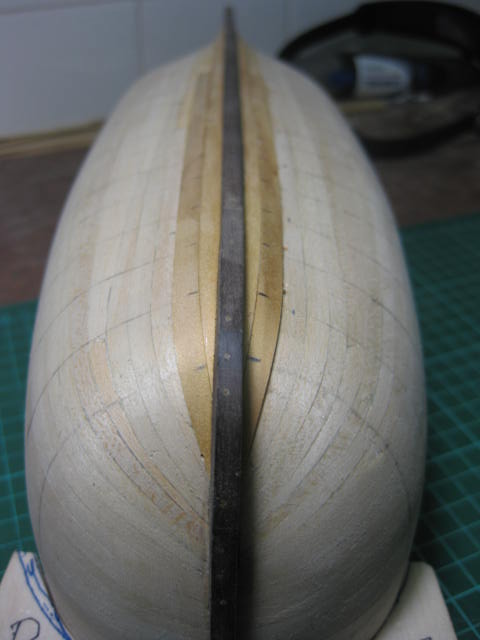
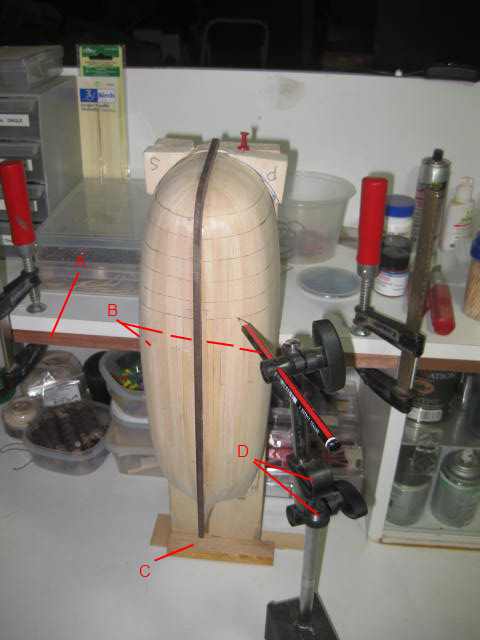
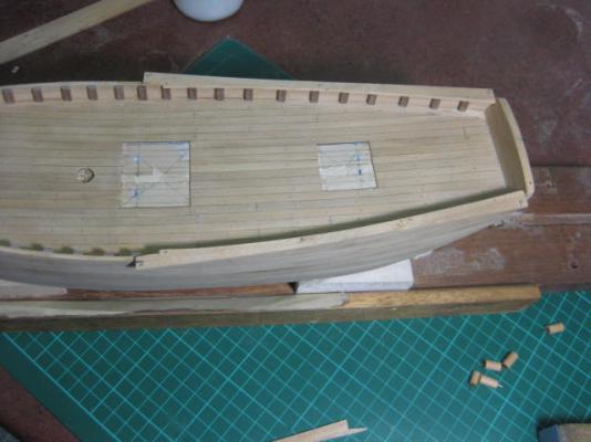
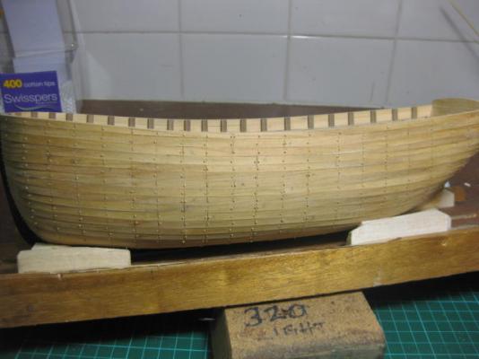
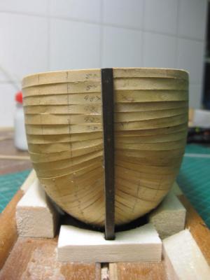
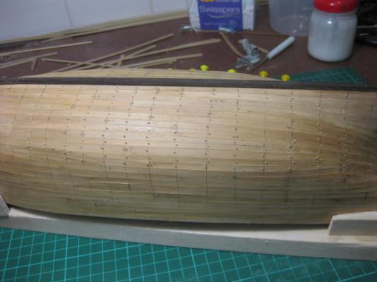
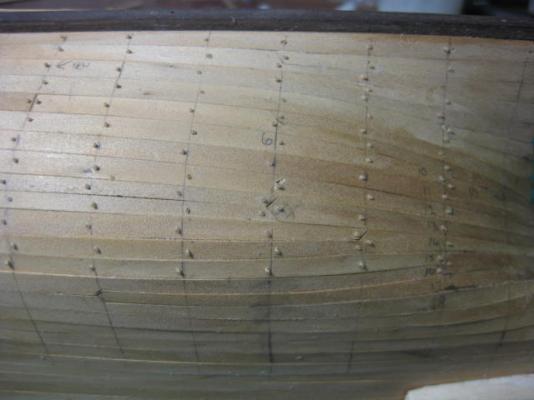
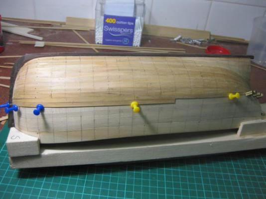
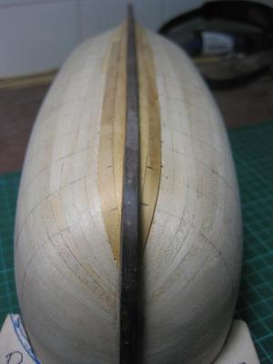
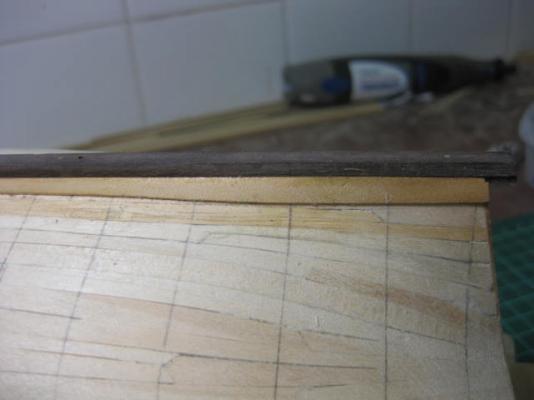
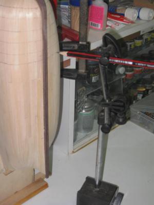
Hull Treenail Marking I thought I'd share my method of marking out the frames for butt joins and later the treenails. I hadn't marked all the frames previously, and more than half of them are actually non-existent anyway - the treenails will "suggest" they are there. First I secured the boat to my planking base, then I clamped it vertically to a shelf above my workbench ensuring the keel was perfectly square to the benchtop in both directions. Then I clamped a pencil to a stand I use for a dial caliper with my Mill. This stand is multi-adjustable and has a good heavy base. I set the pencil to a mark I made in the centre of the first frame and moved the stand/pencil around the hull. This step is repeated for each frame. Result - perfectly vertical markings .

-
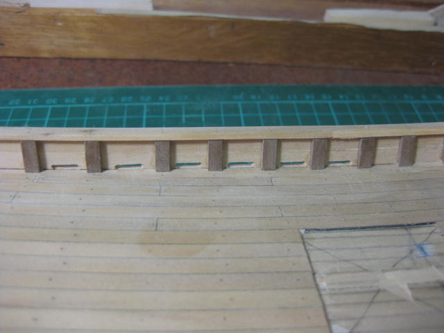
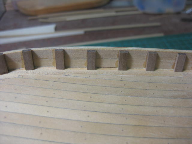
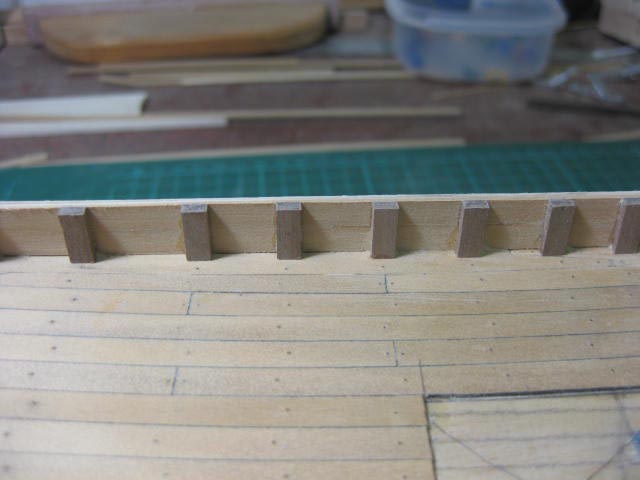
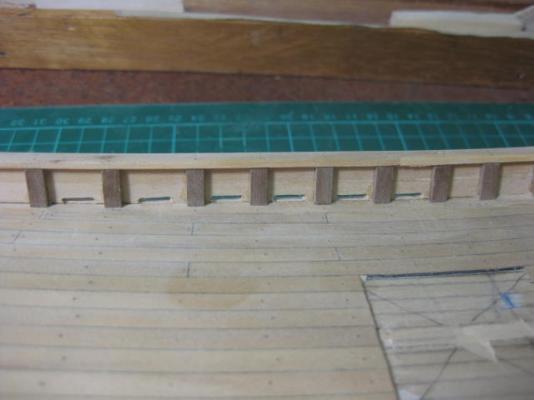
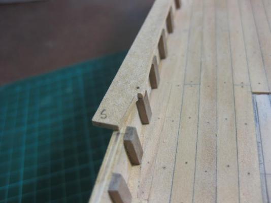
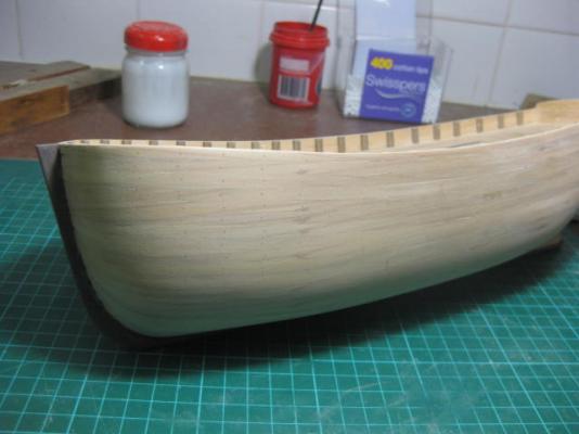
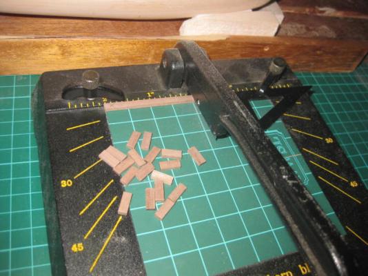
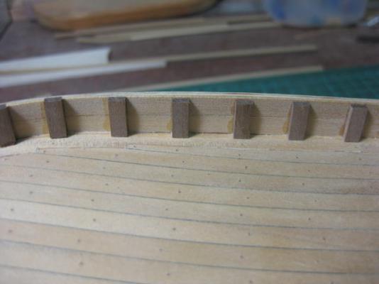
Dummy Frames I cut and fitted the dummy frames to the bulwarks. I cut all 42 pieces on my Chopper - with a stop set up this ensured they were all exactly the same length. When the glue dried overnight I sanded the few tops of the frames that were a little high near the bow and stern, and sanded the bulwarks level with the rest. Very little adjustment was necessary in either case. The hull is now ready for the 2nd planking.

-
Stem and Keel I've scratchbuilt the Stem (I can't help myself sometimes ). I used the kit supplied ply stem as a pattern. I made it from nine pieces of 5mm x 5mm Walnut, jointed like a small ship's stem - at least as best I could do with the size material I had available. A piece of 8mm x 5mm would have come in handy for the Gripe, but it all looks OK. I've taken a leaf out of Underhill's book and treenailed the whole thing together with 0.7mm bamboo - it's incredibly strong. To cut the Rabbet I first marked a line for the cut with a compass, then I used a very sharp Xacto chisel blade to carve it out. This took a while. I touched it up with a needle file. The rabbet in the keel was cut on the Byrnes saw. Finally I fitted both stem and keel.