Dan Vadas
-
Posts
3,261 -
Joined
-
Last visited
Content Type
Profiles
Forums
Gallery
Events
Everything posted by Dan Vadas
-
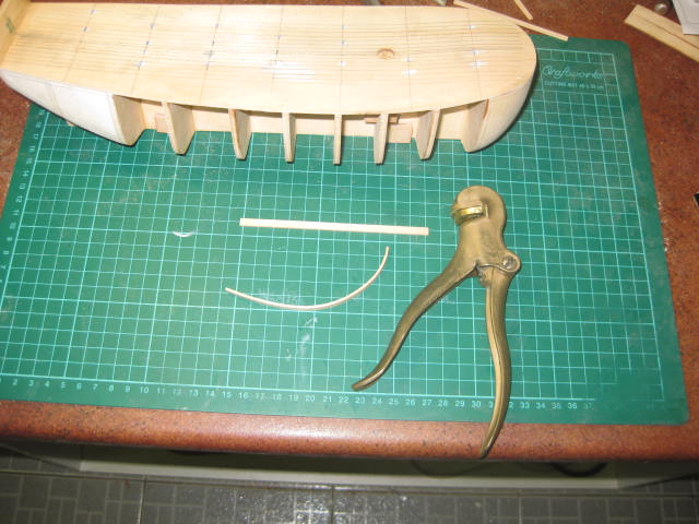
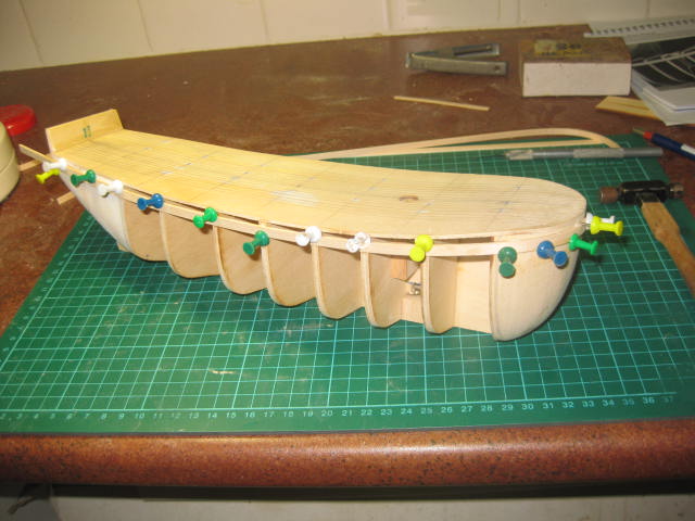
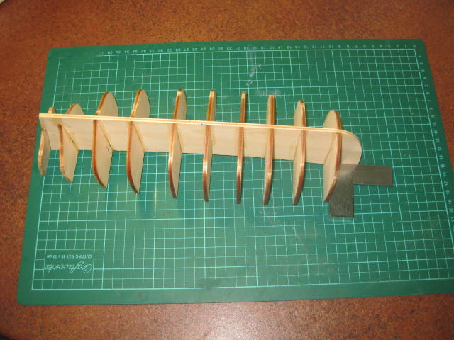
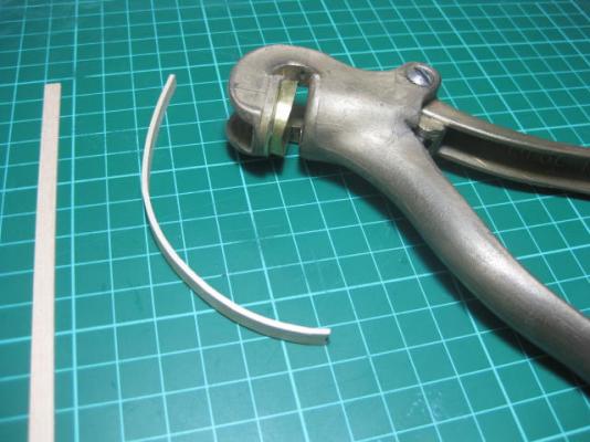
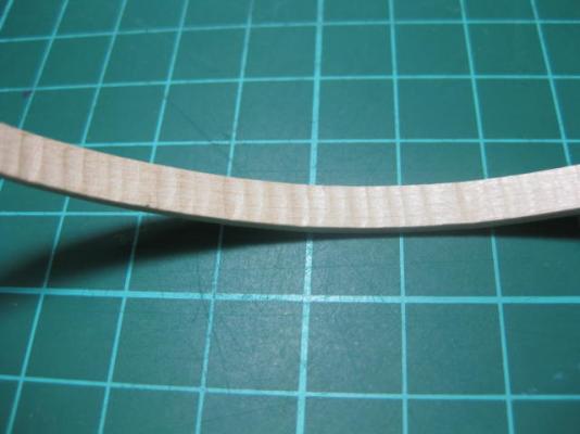
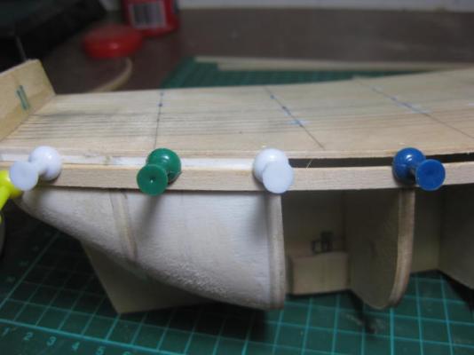
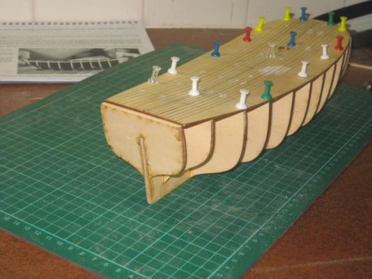
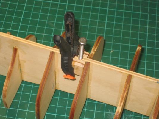
Sheer Strakes The planking has started. I've decided to "double-plank" this kit. I'm not a great fan of double-planking, but I'm making this kit pretty well "out of the box" to assist any other builders who are new to the hobby. I'll be adding my own touches as far as detailing is concerned, and I'll probably deviate from the kit instructions at times if I think there is a better or easier way to do certain things. I'll try to remember to make a note of these additions and/or deviations as I go - others may prefer to simplify a few things. First ones to be fitted are the two Sheer Strakes that will sit hard under the pre-cut ply Bulwarks. These are fitted 3.5mm below deck height for the length of the hull - the bulwarks need support at their lower ends and will be glued in the resulting gap. I started by marking out the 3.5mm line and drilled a 1mm hole in each bulkhead just above the line to take the pins. As the bulkheads are only 4mm thick the pins split them fairly easily, so pre-drilling is necessary. Next I used my Plank Bender (shown below for any newcomers who haven't seen it in use yet) and bent the planks to curve around the bow. BTW - these two planks, and the Garboard planks, will be the only ones that I'll be laying in a full length. The rest will be laid in three sections for easier fitting. I'm doing these four in full lengths to determine an exact line for the others. Then I applied a liberal coating of PVA to both the plank and the bulkheads and held it in place with the plastic-headed push-pins. Note that I don't hammer the pins through the plank itself but alongside it. The shoulder of the pin clamps it to the bulkhead. This avoids splitting the plank, and is the way I do it when "single-planking" to eliminate holes in the planks. I'm leaving the pins in to let them dry thoroughly.


-
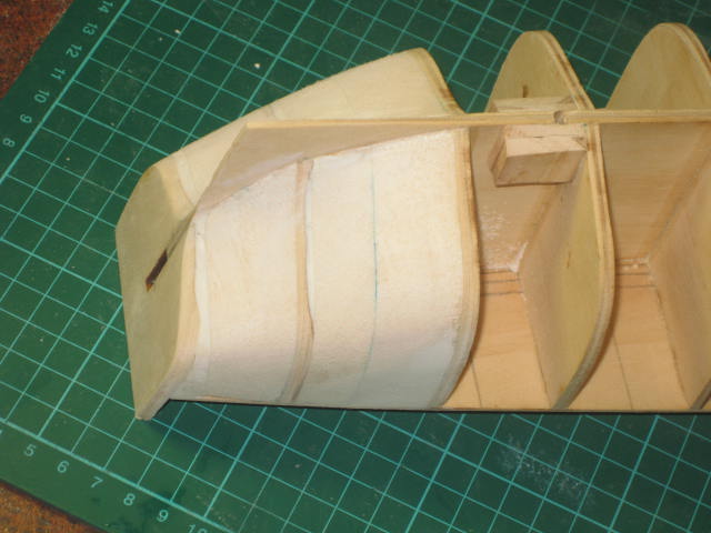
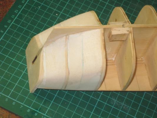
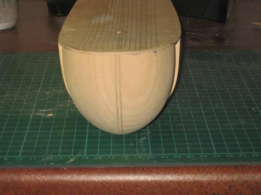
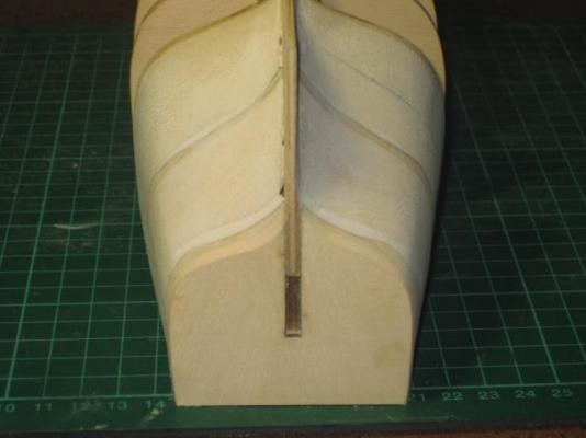
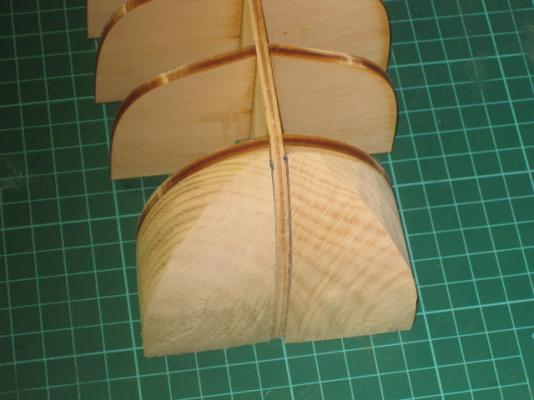
Stern Filler Blocks I've added balsa filler blocks to the stern, and faired the hull. I've also thinned down the Bearding Line. A pretty easy job compared to some I've done in the past - the frames are cut very well in this kit. The kit-supplied Limewood Bow Fillers came up really well - a bit harder to sand than balsa, but they turned out a fair bit more accurately because of that. Looking at the pictures, I still need to touch up one or two areas on the stern blocks.
-
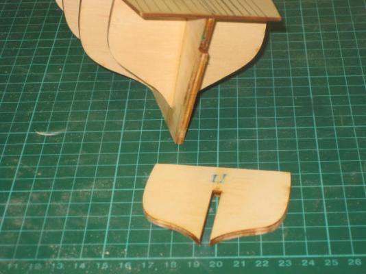
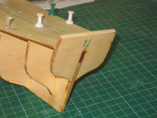
Error in Kit Transom I've discovered another error with the kit. This one's a bit of a trick to work out. Modeller's Shipyard sent a replacement Transom. Apparently there was a problem with the outer shape of the original. The problem is that the slot in the replacement is far too long. If you were to push the transom down until the slot bottoms out (as you would) the transom finishes at deck height. WRONG - the top of the transom should finish flush with the ply bulwarks (to be fitted later), 13mm above finished deck height. I only discovered this after I'd already glued the Transom to the "false keel" - I actually looked at the pictures in the Instruction book (a habit I've unfortunately lost since building the AL "Supply" - the instructions in that kit were so woeful that I threw the book away early in the Build and went my own way). No big deal - a brushing of Isopropyl Alcohol on the glue join, waited 15 seconds (yes .... that's ALL it took) and the transom virtually fell off. I've re-glued the transom at the correct height, now I've just got to wait until it dries. BTW - the last pic was only a "dry fit" for the camera - I've actually turned the transom around so that the bevel on the top is the RIGHT way around. I've also glued a couple of support strips (5mm x 3mm) under the deck on the transom. This should strengthen the whole assembly quite a bit as I'm doing the fairing and planking.
-
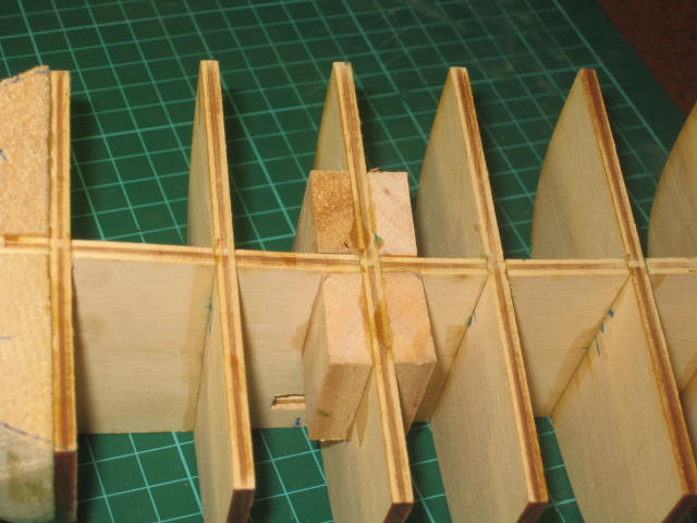
Mast Support Blocks I've also fitted the Mast Support Blocks, which for some reason MS have as being fitted on Page 17 - after the Planking is finished if you are following the Instructions page by page. There seems to be a mix-up in the order of the pages - anyone else doing this kit, please make a note of that. Instead of using scrap ply for these blocks as suggested I cut and used some Pine.

-
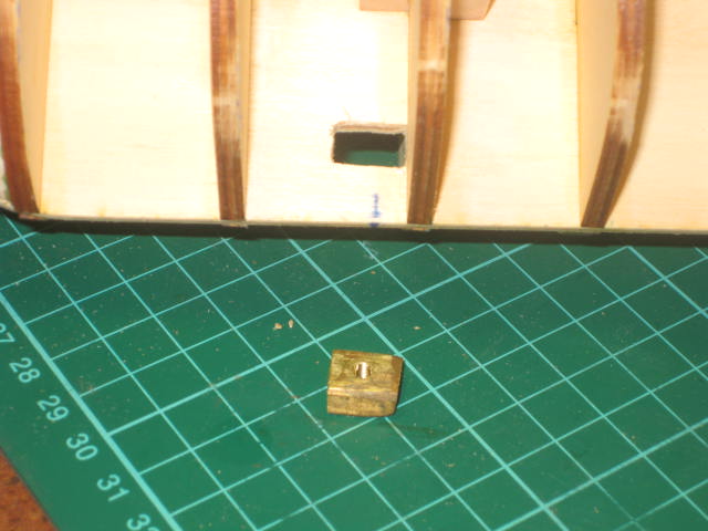
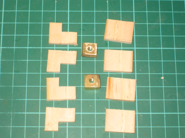
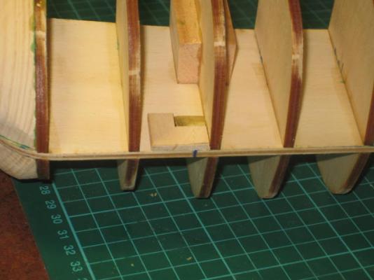
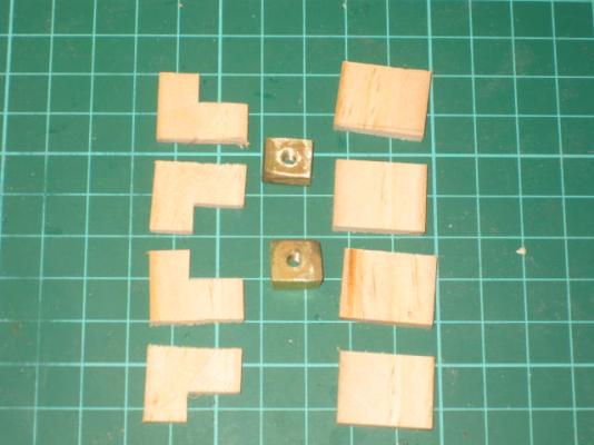
Pedestal Mounting Nuts I've fitted some "nuts" into the "false keel" to which the mounting pedestals will attach at the end of the build. I made two "nuts" from some 10mm x 6mm brass bar into which I drilled and tapped a M4 thread. These will take 4mm Stainless Steel bolts when the time comes. I slotted two holes in the "false keel" to take the nuts. Next I cut four "L" shaped pieces of 3mm pine, and four square pieces from the same stuff. After inserting the nuts into the slots I marked their centres and glued the "L" pieces to the "false keel". When the glue dried I removed the nuts and drilled a 4mm hole on the mark on each, going past the nut about 10mm to allow for any bolt protrusion through the nut. Then I re-inserted the nuts and screwed the two bolts into them to make sure nothing went out of alignment, then epoxied the nuts to the keel and also epoxied the square pieces over the lot.

-
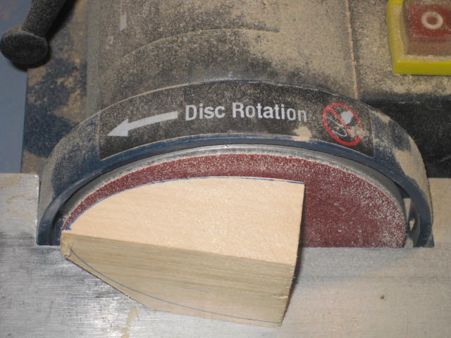
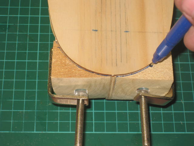
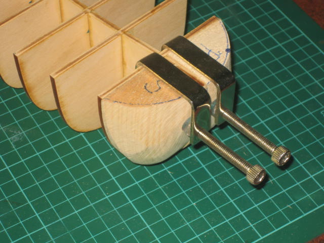
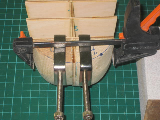
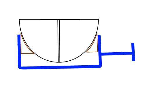
Alternative Method for Clamping Rounded Pieces Another way I've clamped parts like this is shown in the pic below. I shape two pieces of scrap wood that create two parallel faces and glue them to the uneven faces with CA. I clamp the sections together until dry, then cut and/or sand off the blocks. This trick can usually only be done on parts that won't be seen, as the CA would soak into a "finish" piece and create problems later. An alternative to using CA would be to glue some sandpaper to the curved faces of the blocks - that usually supplies sufficient grip.
-
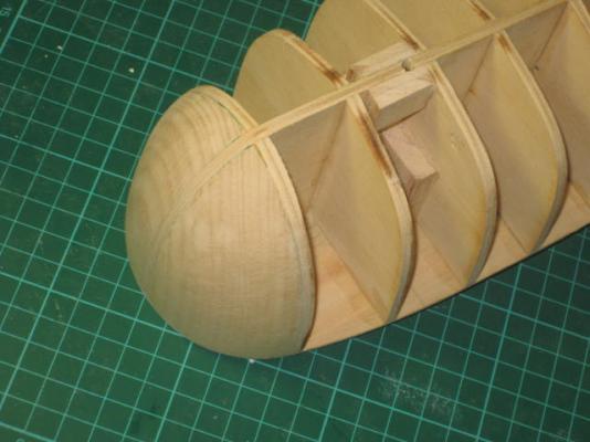
Bow Fillers I've roughed out and glued in the Bow Filler blocks. First thing (no pic) was to trace around the stem and bulkhead #1 on each piece. These are Limewood - kit supplied. A little harder to sand than balsa, but they should take both pins and glue better. The pics are pretty well self-explanatory .... the whole process took me about 20 minutes. The clamping arrangement I used to hold the blocks while the PVA glue dries (overnight). Note the sandpaper glued to the faces of the trigger clamp - stops it from slipping on odd surfaces like this. It's always a good idea to coat BOTH faces of any part you are gluing with PVA to ensure you have a maximum amount of adhesion.


-
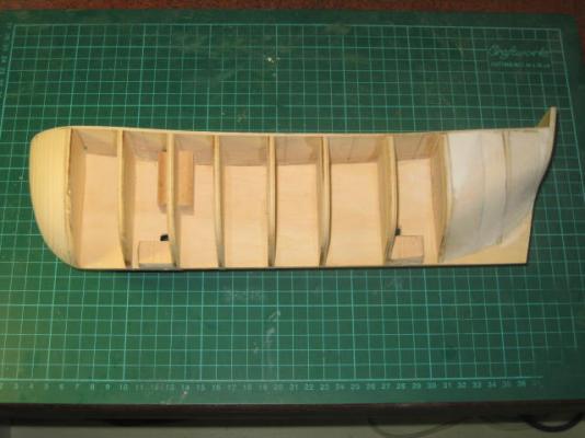
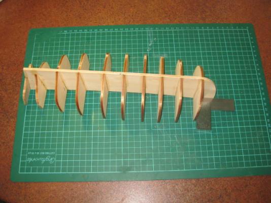
Gluing Bulkheads I've glued the bulkheads to the "false keel". I'm VERY impressed by how easily they went on - no filing needed AT ALL to get a perfect square fit on every one, I didn't need to use any clamps to keep everything straight and square. There's no twist or bend whatsoever in the keel. There's no horrible scorching on the laser-cut edges either, just a slight discoloration which I've left on the bulkheads for now - it gives me a good guide later on when I do the "fairing".
-
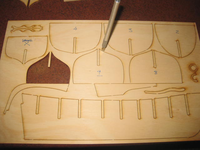
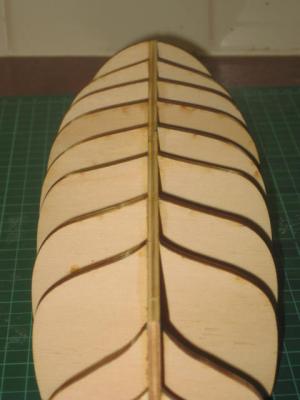
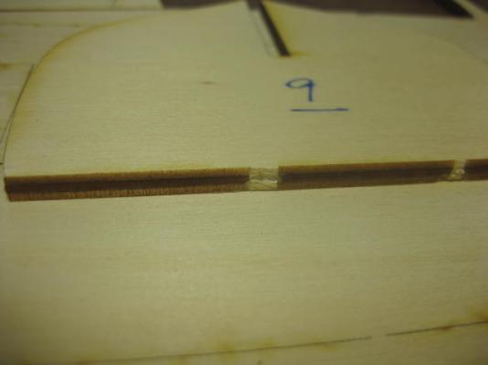
I've made a start, albeit a small one - I've cut the bulkheads and keel off the sheet and trimmed them up. This would have to rate as the best laser cutting I've come across to date - after I cut the two or three bridges on each part with a chisel-point Exacto blade they just about fell out if the sheet and needed almost no trimming at all. I'll leave the sanding of the edges of the bulkheads for when I fair them.

-
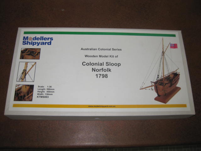
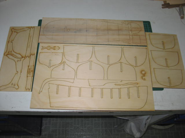
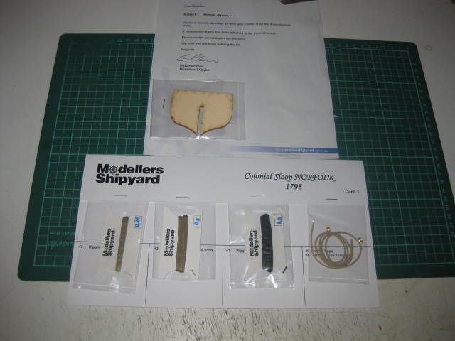
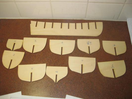
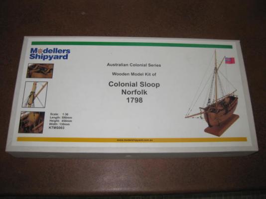
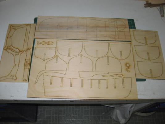
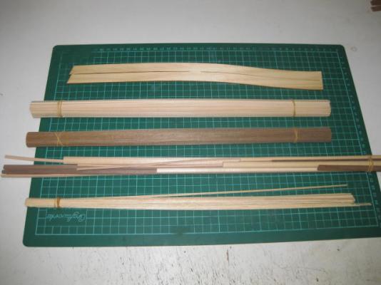
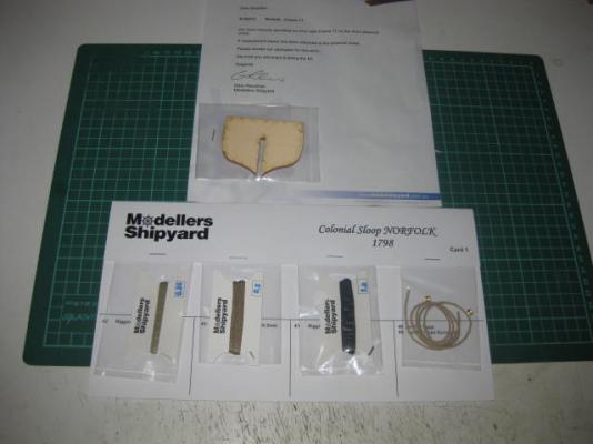
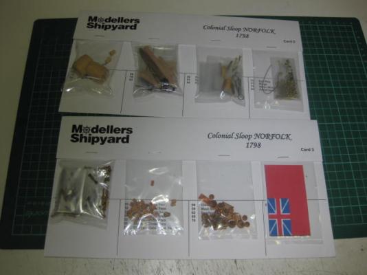
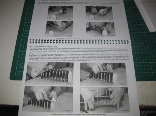
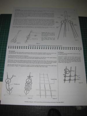
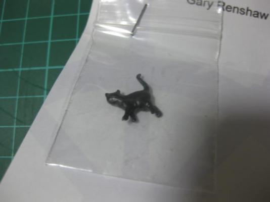
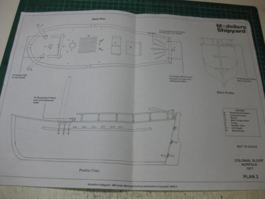
The Kit The Laser cut pieces - keel and frames, and also a stand with a laser engraved nameplate. Quality - very good. The planking for hull and deck .... again, top quality. There are also two laser cut pieces at the top of the pic which will be the bulwarks. A rather small amount of Rigging line (I will probably use Mercerised Cotton instead, I'll see what the kit stuff is like when I open the packs but it looks pretty good). At top of the pic is an extra bulkhead which was sent to me after the kit arrived - there is a slight difference in the width to the originally supplied one, apparently it was an error MS discovered after they'd boxed the kit. I don't really know why they bothered sending it, because the original one was actually a bit TOO big and could have easily been faired into shape. A nice, and professional, gesture however. The pack of Fittings ... again look very good quality. Some of the plans and instructions .... quite a large booklet of them including a full size plan and side view. Some very good tips for novices are included, but the "planking" section isn't the way I'll be doing it. A quaint little touch from MS - Matthew Flinders' cat "Trim", which he took on all his voyages. I have a copy of the book "Matthew Flinders' Cat", which is quite a good account of his voyages and well worth a read.
-
Hi all, Thanks to the generous help of MSW member "lister" (Dave) who had saved my entire Build Log of the Norfolk Sloop before the Great Crash of February 2013 I've been able to reconstruct this build log. I haven't included all the comments from the members who were following it, and for that I apologise - that would have been impossible as the posts can only be made by those members. I thank all those who followed my build at the time. I have included a few pertinent quotes that changed the course of how I built the model. My thanks go out especially to John (Jim Lad), Anton (perthshipbuilder), John (Neptune), Jan (amateur) and David (hopeful) for their contributions in making this model as accurately as possible. Below is an "Index to Points of Interest" for those who wish to see a particular stage of the build. Index The Kit Gluing Bulkheads Bow Fillers Pedestal Mounting Nuts Mast Support Blocks Stern Filler Blocks Sheer Strakes Garboard Strakes - 1st Planking Plank Taper Calculations Plank Battens Hull 1st Planking Bending Bulwarks Deck Planking Margin Planks Deck Treenailing Fitting Bulwarks Stem and Keel Dummy Frames Hull Treenail Marking Hull 2nd Planking Garboard Strakes - 2nd Planking Making Treenails Treenailing Hull Making Grating Cap Rails Scuppers Gunwales Channels Grating and Surround Companionway Hull Lacquered Elm Tree Pumps and Windlass Barrels Rudder Mast Bowsprit Gaff and Boom Catheads Fitting Bowsprit Deadeyes and Chainplates Mast Hoops Shrouds Backstays 1 Forestay Topmast Stay Backstays 2 Bowsprit Shrouds Ratlines Fitting the Gaff Boom Stop Sheet Cleats Tiller Throat and Peak Halyards Sheet Horse Boom Sheets Boom Cheeks Jib Rigging Railings Anchors Making Sails Bolt Ropes Robands and Reef Points Fitting Gaff Fitting Jib Model Finished Making the Stand
-
Spencer, it depends on how you want to build the model - Fully Framed, Fully Planked, or a combination of the two (i.e. one side Framed, one side Planked as I'm doing with my "Vulture", or maybe another combination). Let me know, and then I'll advise you on the best way to get out of your dilemma - you have one which ever way you go. Danny
-
Certainly. Danny
-
Thanks John, It sets enough in about a minute or so to no longer need clamping, even on these pieces which I didn't bother soaking first to follow the deck roundup - in fact for a few other flat things I did earlier I just held my fingers on the piece for a few seconds instead of using clamps at all . It's just a fast-setting PVA, so I guess it's as chemically stable as the normal stuff. Danny
-
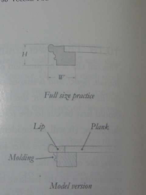
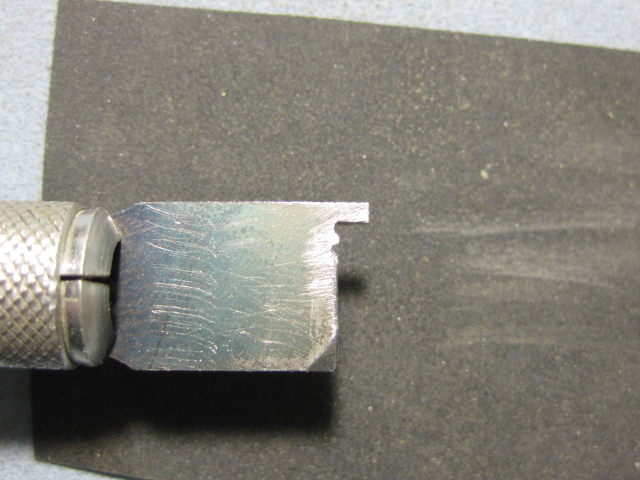
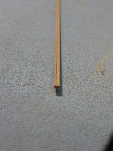
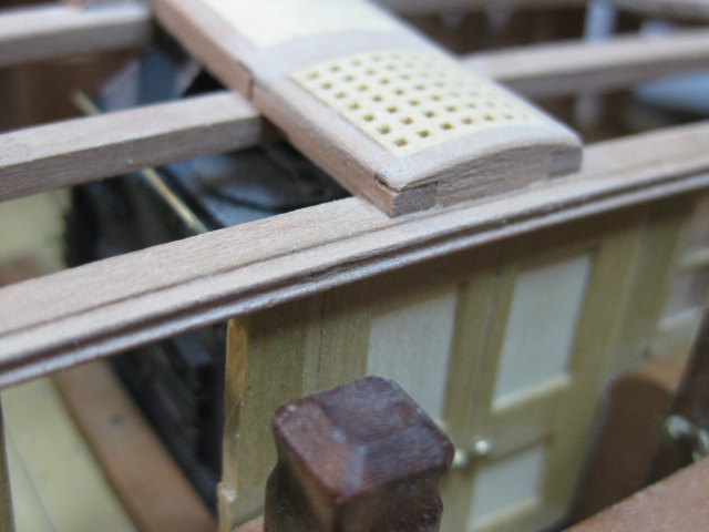
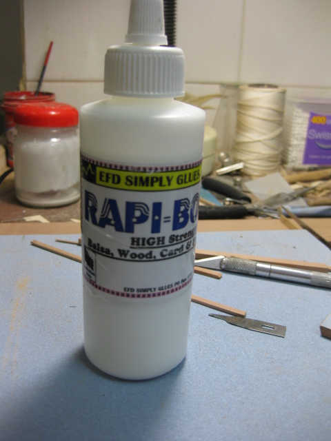
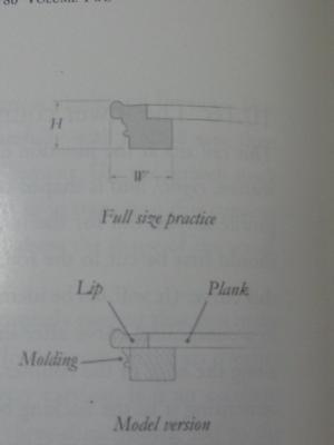
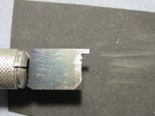
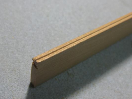
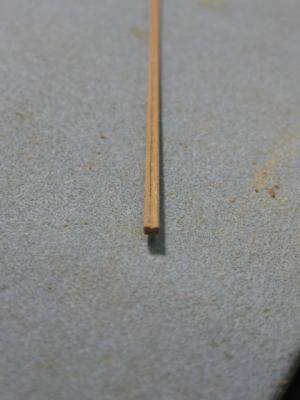
Breast Beams The aftermost beam on the Forecastle and foremost beam on the Quarterdeck are known as Breast Beams. These are shaped differently to the other beams in that they have a rabbet to accept the ends of the deck planking and a molded spurnwater on the top edge. There is also a decorative molding beneath the outer edge: The beam was originally made from heavier stock in one piece to add strength to the edges of the decks. I chose to make them from three pieces - a "normal" beam, the rabbeted top and the molding. When all glued together there is no difference apparent as the joints are hidden. To cut the molding I filed a scraper from a square ended Xacto blade : To attach the moldings I used a High Strength PVA glue named Rapi-Bond which I found recently. This stuff sets almost as fast as thick CA, and has a lot more bond strength than the Fullers Maxbond I've used to date : Some pics of the moldings being fitted : Danny the fore

-
Thanks again Christian, Joe, Alex, Raphael, Aldo, Brian, Dave, Rob and David for your kind comments and words of advice . Rob, I use a silver solder paste - medium melting point. For the blackening I used Birchwood Casey Brass Black which I bought from a gun store - similar stuff to the one you use I guess, but it doesn't work on copper unfortunately. It blackens it, but the black rubs straight off again . David, I was aware of the different melting point grades of the solder paste. I only have the one at the moment (medium), it's not cheap (about $25.00 per tube but it goes a LOOONG way ) and I have to import it from the US - as I don't have a lot more multiple joint soldering to do on this model I'm holding off on getting any other grades for a while. Danny
-
Thanks very much for the info and the Link to the video Jim - that model of Surprise is AWESOME . Here's a Link to the Youtube page it's on - there are many more videos of R/C squareriggers that can be viewed from the page, including one of Surprise firing her guns .... that's a MUST WATCH . HMS Surprise Radio Control Video HMS Surprise firing her guns Danny
-
Toni - don't bother at all with trying to keep the lower decks clean of sawdust .... you still have A LOT OF IT to be done ON the model, and it's impossible to keep out. Save that for when the hull is FULLY COMPLETED. I've been using a similar method to Ed, along with inverting the hull a few times to shake out all the shavings and other debris. I flexible plastic hose which you can use either manually (stick it in your mouth and blow, or if you don't mind the taste of sawdust .... suck ) or attached to a low-pressure compressor can also work wonders . Danny
-
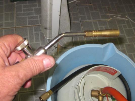
Thank you Mark, Brian, Janos, Druxey and Adeline. Brian, I'll write a tutorial when I learn how to silver solder properly . Janos - Birchwood Casey Brass Black. Druxey, thanks for the new info about Yellow Ochre". Must try that soon. One problem I had was transferring the heat in the right direction due to the round surface, another was the thickness of the pipe compared to the smaller pieces. My Micro Torch was inadequate for the job of soldering the two pieces of pipe together, and I had to resort to my "big" torch (see below) : I kinda figured the big fella would have made a brass puddle out of the slides and handles rather rapidly . Danny
-
We have had a few requests from builders of Small Craft to categorize their Build Logs to make finding similar vessels easier using the Advanced Search function. The solution is to have the word "SMALL" in the Build Log Title, then you could Search for all the small builds like you can for PLASTIC, CARD, BOTTLE and RADIO by simply Searching for the word SMALL in the Title using Advanced Search. Unfortunately it would mean a LOT of work by the Moderators to find and rename all the Small Craft build logs already in place (and even new ones), especially those that haven't named their Build Logs clearly, or some of the more obscure vessels we are unfamiliar with. There's nothing stopping those builders who would like their boat categorized in this way from renaming THEIR OWN build logs with the word SMALL in it. Place the word AFTER the name of the vessel and builder's name as in this example : Lobster Smack by Joe Bloggs - SMALL Note that there must be Spaces in the positions as shown, or the Search won't find it properly. You need to go to the FIRST POST of your build log, click on the Edit Button and then on the "Use Full Editor" Button. This brings up the Edit Box with your Title in it. Edit the title and click the "Submit" button.
-
Yeah - except you can't buy them :D . Danny
-
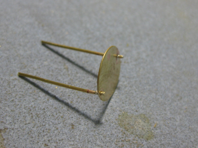
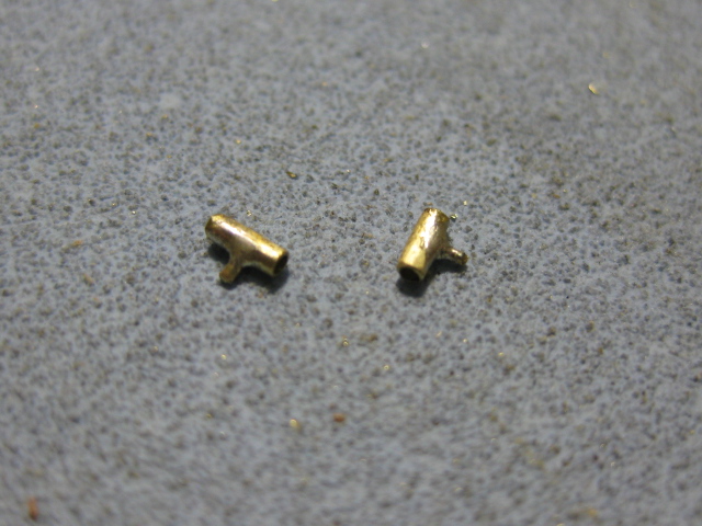
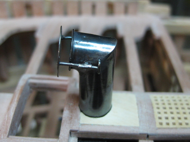
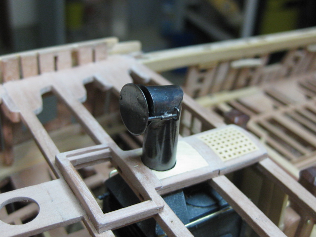
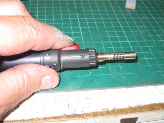
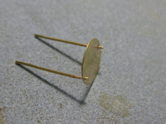
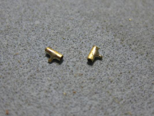
Thanks John and Ben, but "you ain't seen nuthin' yet " . Cowl Baffle There is a wire reinforcing ring around the rim of the cowl. This was silver soldered on and cleaned up. A baffle is attached to the opening of the cowl to regulate air flow to the stove's firebox. I cut a disc of 0.3mm sheet, drilled two 0.7mm holes through it and silver soldered the two sliding pins. I filed the protruding ends down to simulate a peened over end. Next I fabricated two sleeves for the slides to travel in from 0.75mm ID tubing and a 0.5mm pin to locate them correctly. These were CA glued into the cowl - too much heat would have been needed to solder them in and I risked destroying my previous work. Finally two wire handles were drilled into the cowl and CA'd in. The whole assembly was blackened in stages and polished. Danny


-
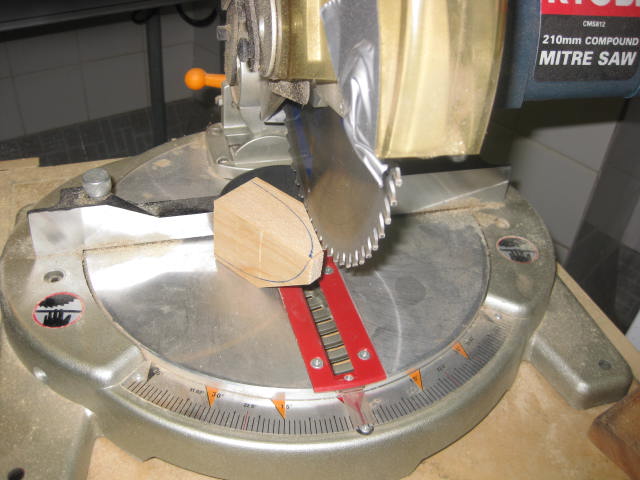
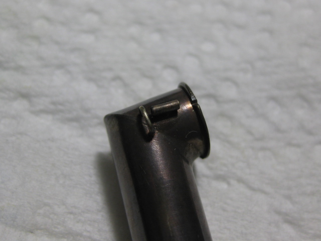
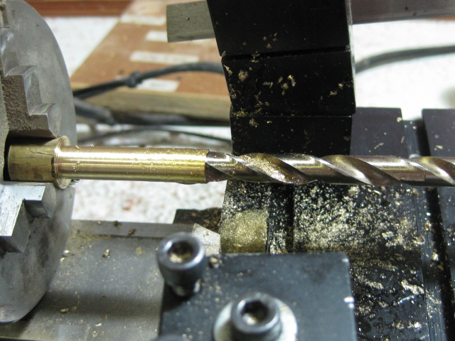
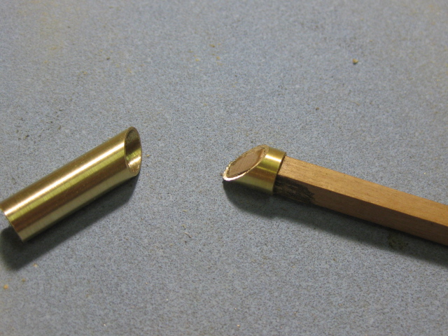
Galley Cowl Time for some more brass work. The Galley Cowl is 15" in diameter, which scales down to 8mm. The top piece is fitted at a slight angle upwards, about 95 degrees at the join. I turned the outside diameter first from a piece of 10mm stock - the closest I had. Then I drilled the centre out to 7.5mm - in several steps starting with a 3mm pilot hole : I made the piece about 5mm longer than needed to allow for a bit of final trimming. I cut the pipe using a fine hacksaw in a mitre box, and finessed the angle to 47.5 degrees on both pieces using my disc sander. I used a piece of scrap to hold the smaller piece - saves burning or sanding down fingers : The finished article after silver soldering ready for some small details. The assembly will be blackened when it's complete : Danny


-
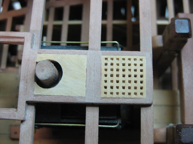
Thanks John, Brian, Sjors and Joe . Sometimes Brian, depending on how deep inside the hull the piece goes. There is no finish applied to the gratings and coamings so far. The "holder" is called a "Coaming" Sjors, and yes - the grating is sanded to the same shape after gluing it in. :cheers; Danny
-
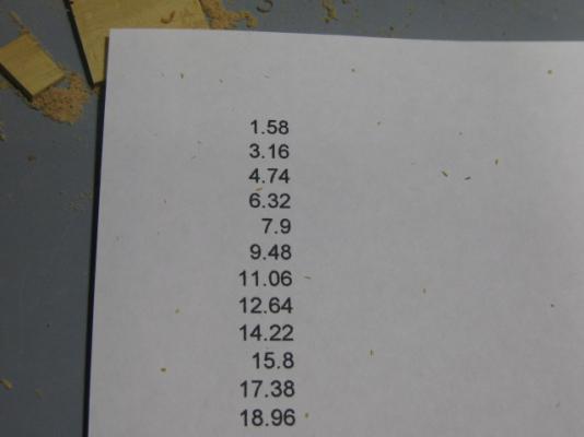
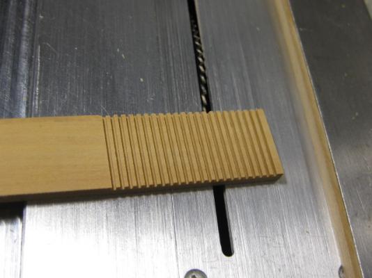
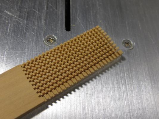
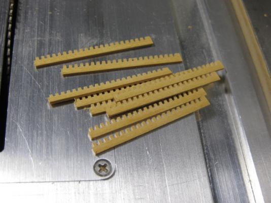
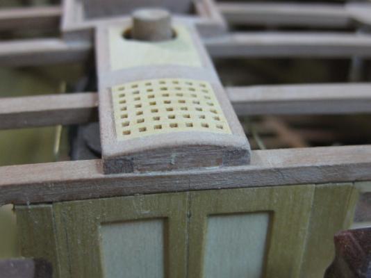
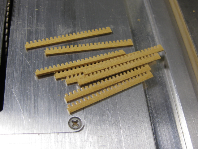
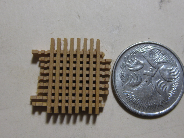
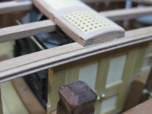
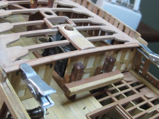
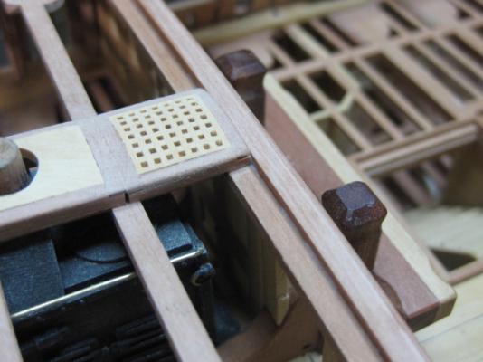
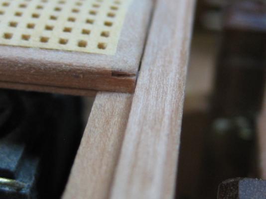
Steam Grating I've made my first (and maybe ONLY) Grating - this goes over the stove. I'm a bit reluctant to make too many more (maybe some on the quarterdeck) as they hide too much detail beneath. The grating stock is 0.79mm thick English Box, a fraction oversize (they should be 0.75mm) but I decided to make them the size of a 0.030" kerfed saw blade on the Byrnes saw using the Micrometer Stop. My first job was to make a list of the spacings (i.e. the Micrometer stops) using a spreadsheet. This made it a lot easier to work out accurately than trying to remember and then calculate each one (especially if I'm interrupted ) : Then I set up a piece of 2mm thick stock and started cutting 18 slots halfway through using the micrometer to set up each one (I made a couple of spares "just in case" - I needed them too ): Then I cut each strip off against the fence, again using the micrometer stop. The measurements are identical to the previous cuts : Assembly is the same as using kit gratings (fiddly, but at least they were cut more accurately than most kit ones). I dipped the grating into diluted PVA and let it dry : After sanding the grating to size and gluing it into place I sanded the roundup in. I've also fitted the Cowl Base : Danny