.jpg.6c90d67e7e9071af590f4d4a2a8bc908.jpg)
Waldemar
-
Posts
986 -
Joined
Content Type
Profiles
Forums
Gallery
Events
Everything posted by Waldemar
-
.thumb.jpg.c6343966b029e7941df5b987d129aac6.jpg)
Mathew Baker's early concept of ship hull design, ca. 1570
Waldemar replied to Waldemar's topic in Nautical/Naval History
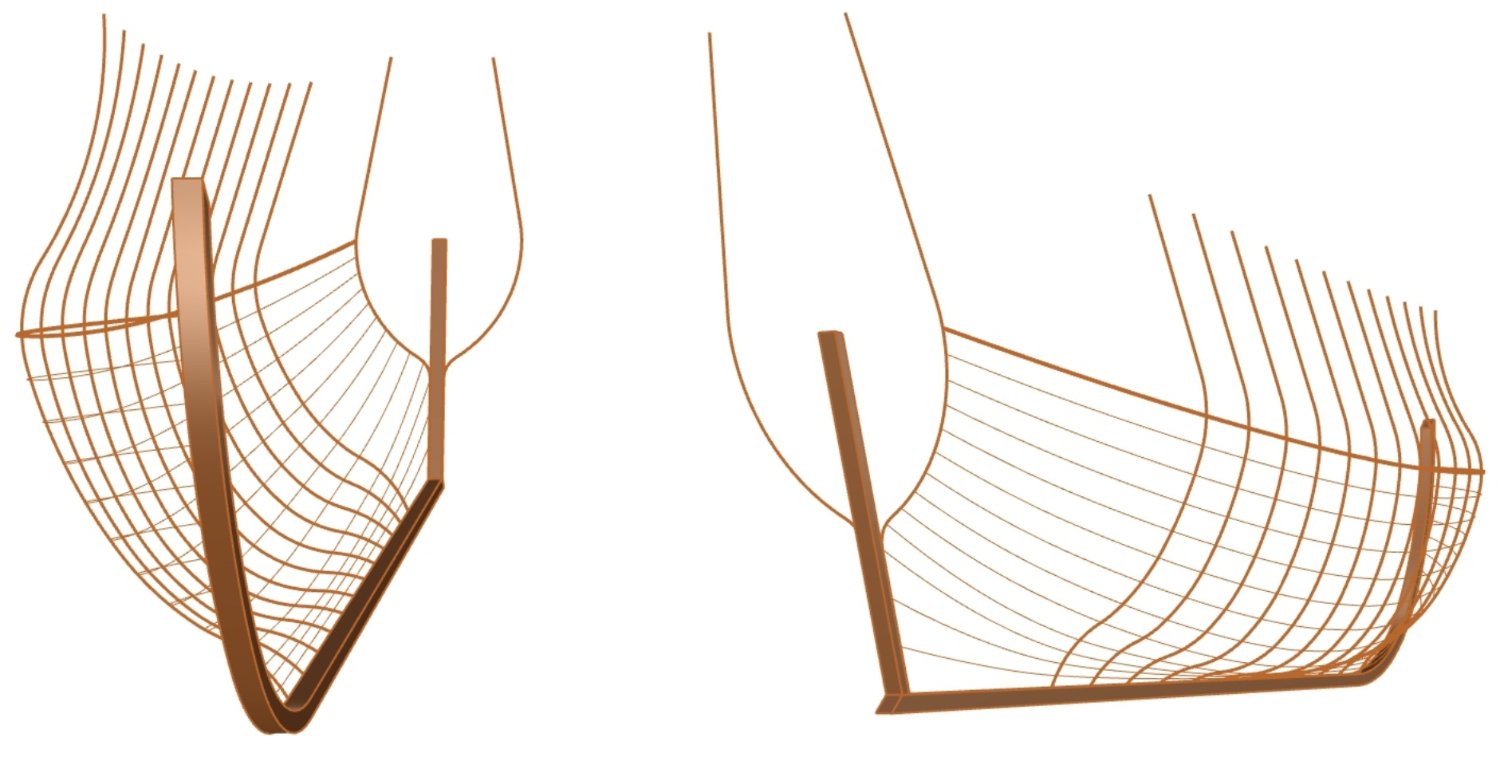
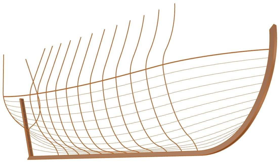
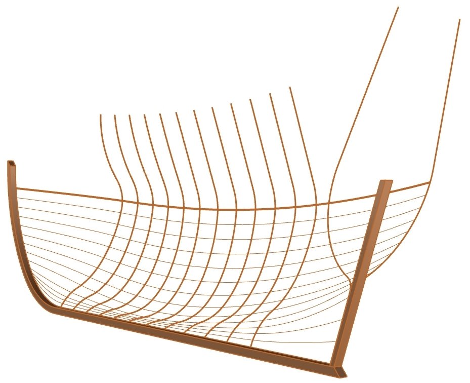
How exactly was this done? Many works have been written about the Mediterranean method, but by far the best single modern work is Le maître-gabarit, la tablette et le trébuchet. Essai sur la conception non-graphique des carènes du Moyen Âge au XXe siècle by Éric Rieth (1996). Below are some renders of a schematic 3D model of the ship drawn by Baker, made using the Mediterranean method. The pre-designed frames are located only between the quarter frames. The shape of the other frames, close to the ends of the ship, was determined by longitudinal ribbands. These elements can be seen in the graphics below. The overall shape and specificity of the lines obtained bear a striking resemblance to the hull shape of an Iberian whaling ship, the famous Red Bay vessel.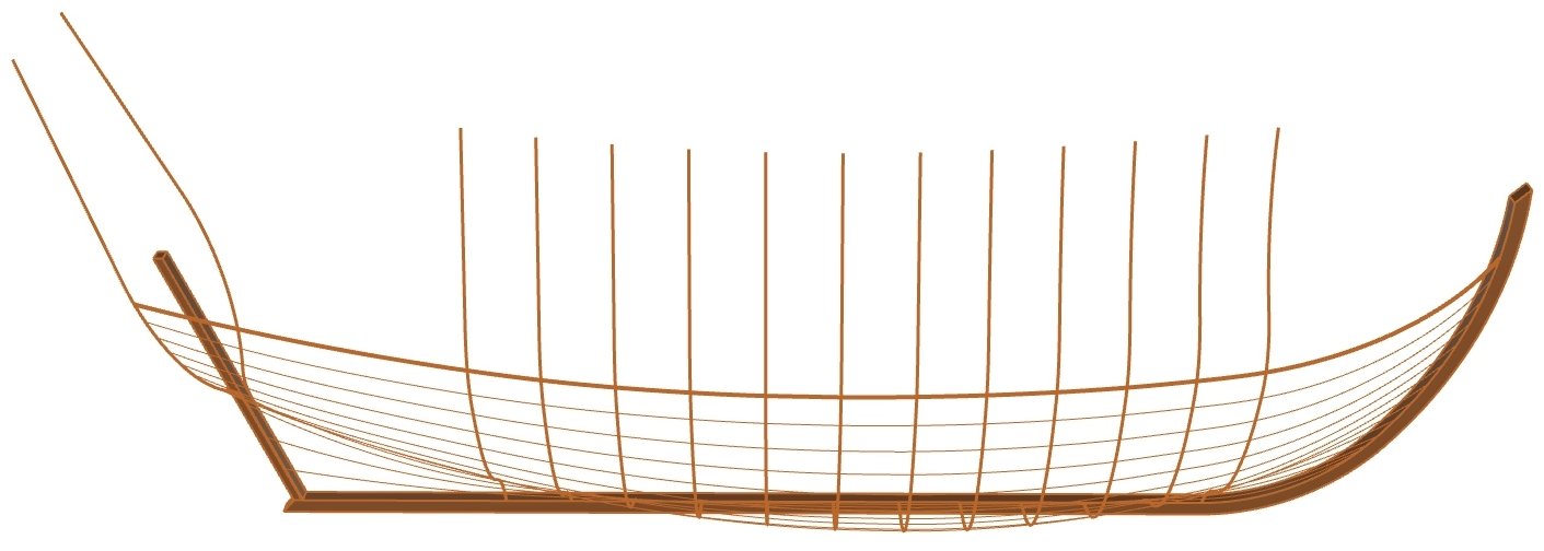

-
Mathew Baker's early concept of ship hull design, ca. 1570
Waldemar replied to Waldemar's topic in Nautical/Naval History
The following reproduction of a circa 1600 plan (from the Russian archives), possibly made by David Balfour, also confirms that contemporary designers did not treat the deadrise as an integral part of the designed frame shape, but rather as a necessary add-on. Again, the deadrise is outside the design grid, unlike all the rest of the frame profile. It is fair to say that a similar approach is taken by modern researchers, forgetting or deliberately omitting deadrise curves from their graphical reconstructions. Therefore, when conducting one's own research, one cannot rely only on modern interpretations of historical material.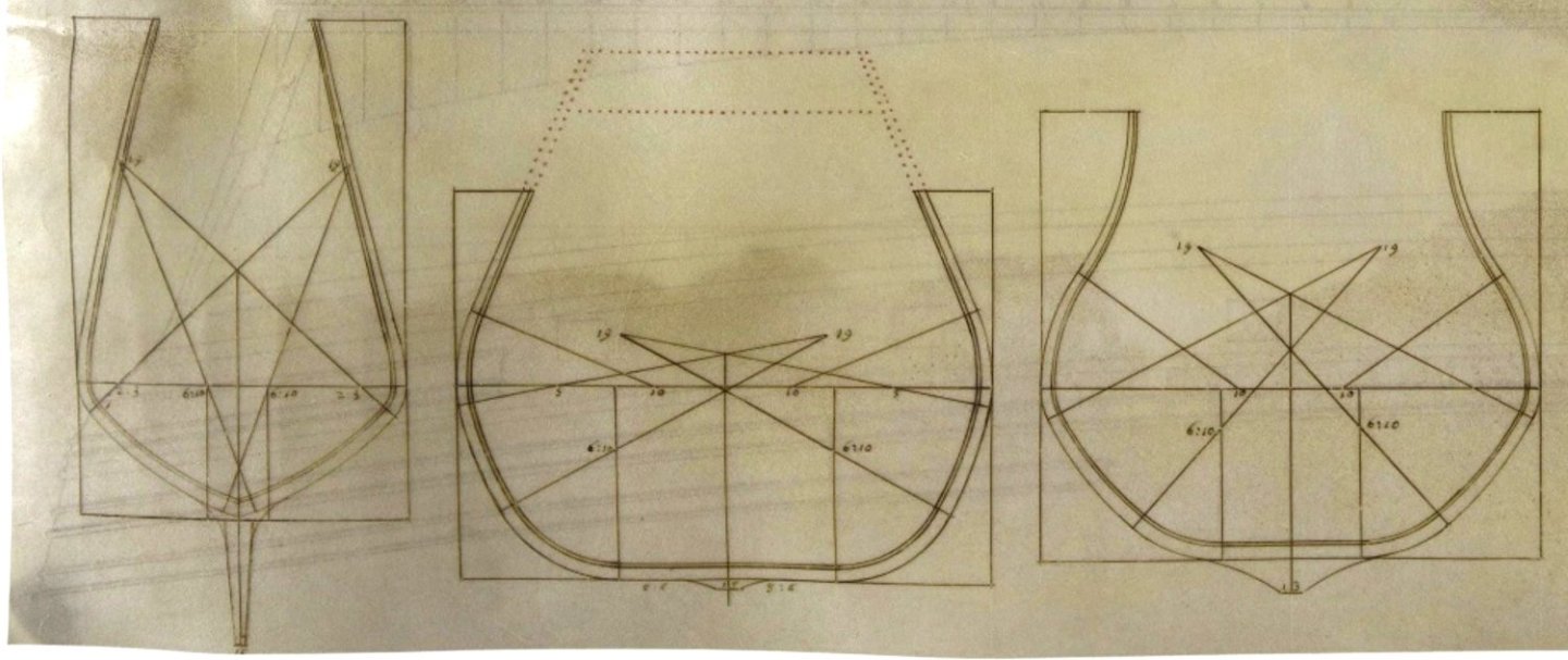
-
Mathew Baker's early concept of ship hull design, ca. 1570
Waldemar replied to Waldemar's topic in Nautical/Naval History
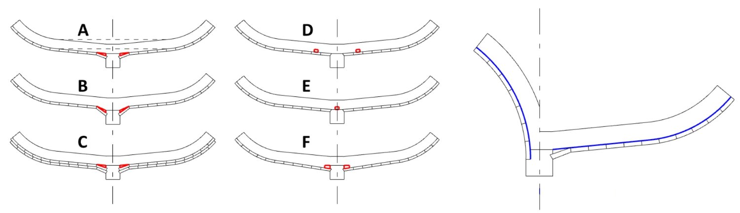
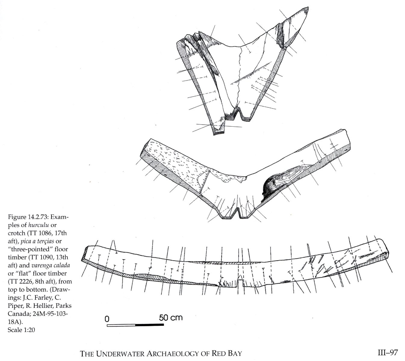
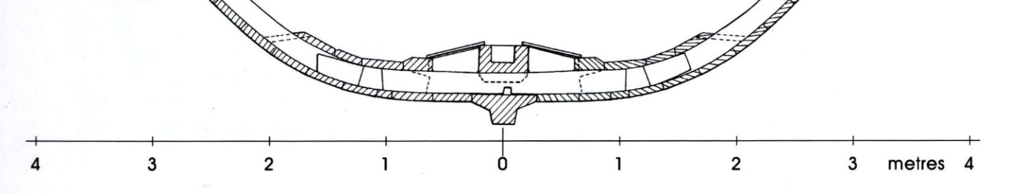
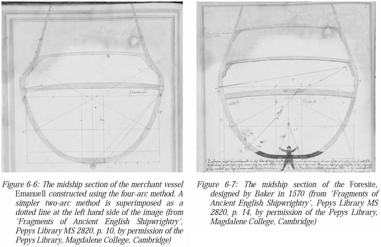
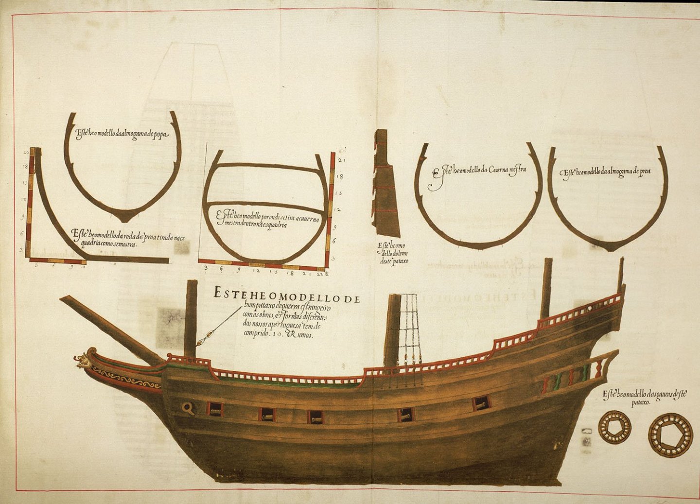
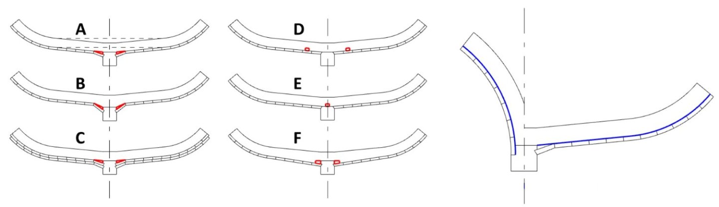
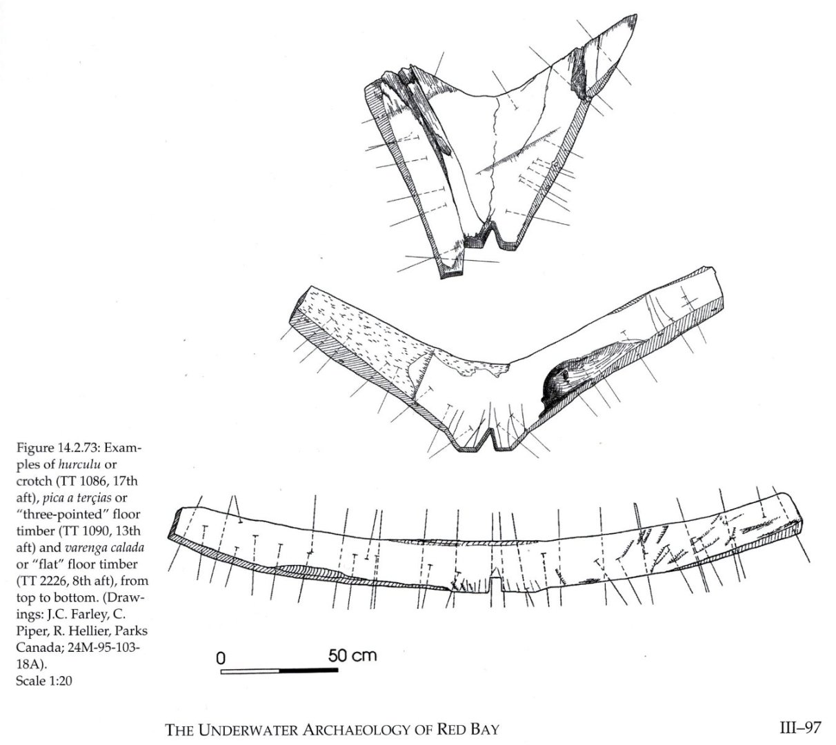
It will also not be out of place to show some examples found in shipwrecks and other written sources. It is clear that the deadrise curves for the main frame could be either concave or convex (the latter even mentioned in the Newton manuscript). Mary Rose (from The Tudor Warship Mary Rose by Douglas McElvogue): Basque whaling ship (from The Underwater Archaeology of Red Bay. Basque Shipbuilding and Whaling in the 16th Century, 2007). In this case the weakening of the floor timbers was to some extent compensated for by the T-shaped keel: Two examples of midship moulds from Baker's manuscript, the one on the left with the deadrise drawn in (from The Gresham Ship Project. A 16th-Century Merchantman Wrecked in the Princes Channel, Thames Estuary. Volume I: Excavation and Hull Studies, 2014): An instructive example also comes from the manuscript by the professional shipbuilder Manoel Fernandez, Livro da Traças de Carpintaria (1616). As can be seen, he designed the midship frame without the deadrise. It was then added later as a kind of supplement in a ready frame (compare two frames shown in the center of the draught). And some other archaeological examples or taken from shipbuilding period manuals, as drawn by me a few years ago: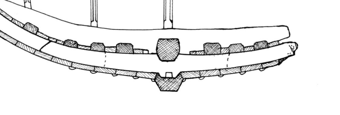
-
Mathew Baker's early concept of ship hull design, ca. 1570
Waldemar replied to Waldemar's topic in Nautical/Naval History
Hi Mark, Yes, this is all correct. Thanks to the improved quality of the reproduction of the Baker's plan, I was able to update the midship mould (shown below). As it happened, this only affects the deadrise, which was raised from 3 inches to 4 inches, at the expense of the keel height, reduced from 12 inches to 11 inches. Here I would also add that in the Harriot manuscript deadrise is specified for small ships at two inches and for large ships at three inches. I have also made other similar minor adjustments here and there, but these are without major impact on the overall reconstruction. For example, the keel length was increased from 60 to 60.5 feet.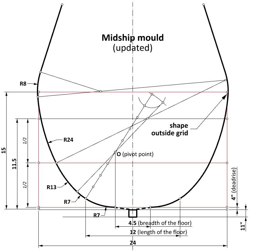
-
Mathew Baker's early concept of ship hull design, ca. 1570
Waldemar replied to Waldemar's topic in Nautical/Naval History
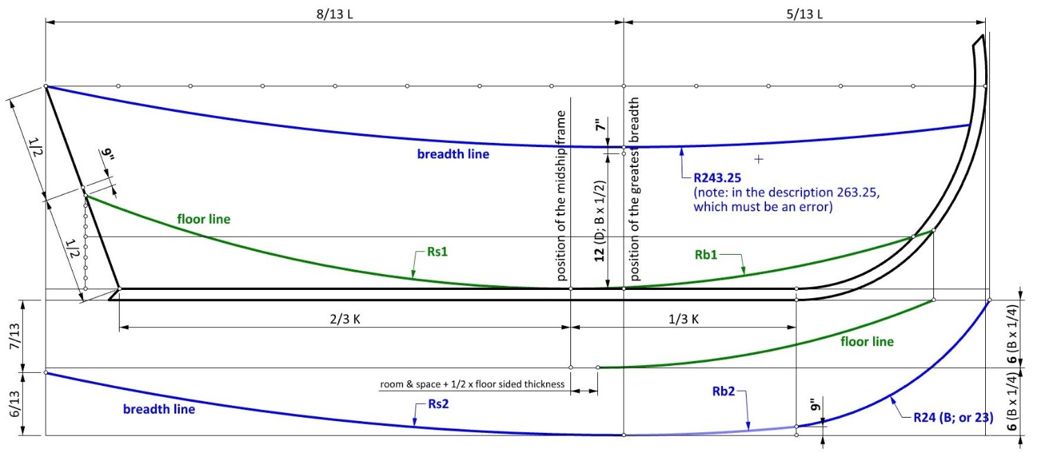
By a happy twist of fate, I found in my home resources a better copy of Baker's plan. This was decisive. After a few minor changes and amendments, the pure Mediterranean method clearly emerged. Taking into account inaccuracies of the original plan and to a lesser extent its later distortions, I find the resulting reconstruction of the lines satisfactory, finally revealing the method used by Baker. Two further detailed comments need to be added to the accompanying drawing. Baker deliberately did not draw the narrowing line of the floor for the stern section of the hull, because it was not necessary: he simply took the relevant coordinates for the stern quarter frame from the bow quarter frame. Of minor importance from the conceptual point of view, the radius of the breadth arc for the bow quarter frame is smaller than the rest.
-
Mathew Baker's early concept of ship hull design, ca. 1570
Waldemar replied to Waldemar's topic in Nautical/Naval History
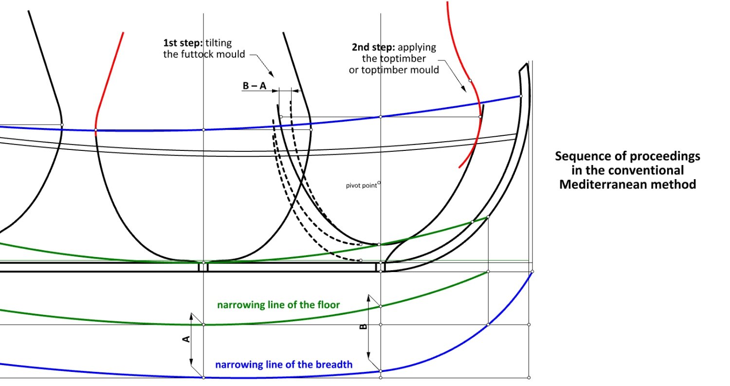
A slightly different interpretation is also possible, closer even to the Mediterranean ways. The difference in the formation of the frame shape would be that the futtock template was moved and tilted first, and only then the toptimber mould (or the actual toptimber during skeleton assembly) was applied. This interpretation also explains well the slightly larger width of the actual ship compared to its design breadth. More clearly, this is the result of the Mediterranean method of frame forming combined with the adoption of a convenient round value for the futtock sweep radius. In addition, it may be related to the anomaly already mentioned that the position of the midship frame does not coincide with the greatest width of the hull. Normally, the Mediterranean method was used in a non-graphical way, i.e. without the use of a plan, so it is likely that Baker may have tried to sort it out in this way while making his drawing. It is now rather impossible to decide which of the two interpretations is correct (dimensional differences are rather negligible in this particular case). If one accepts the second, Baker's drawing would probably be the only drawing from the era that shows graphically the pure Mediterranean method. However, if one accepts the first interpretation, it could be considered to represent an intermediary between the Mediterranean method and the methods known from the slightly later other English manuscripts on shipbuilding.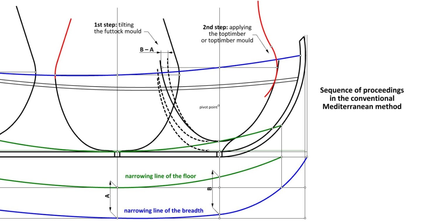
-
Mathew Baker's early concept of ship hull design, ca. 1570
Waldemar replied to Waldemar's topic in Nautical/Naval History
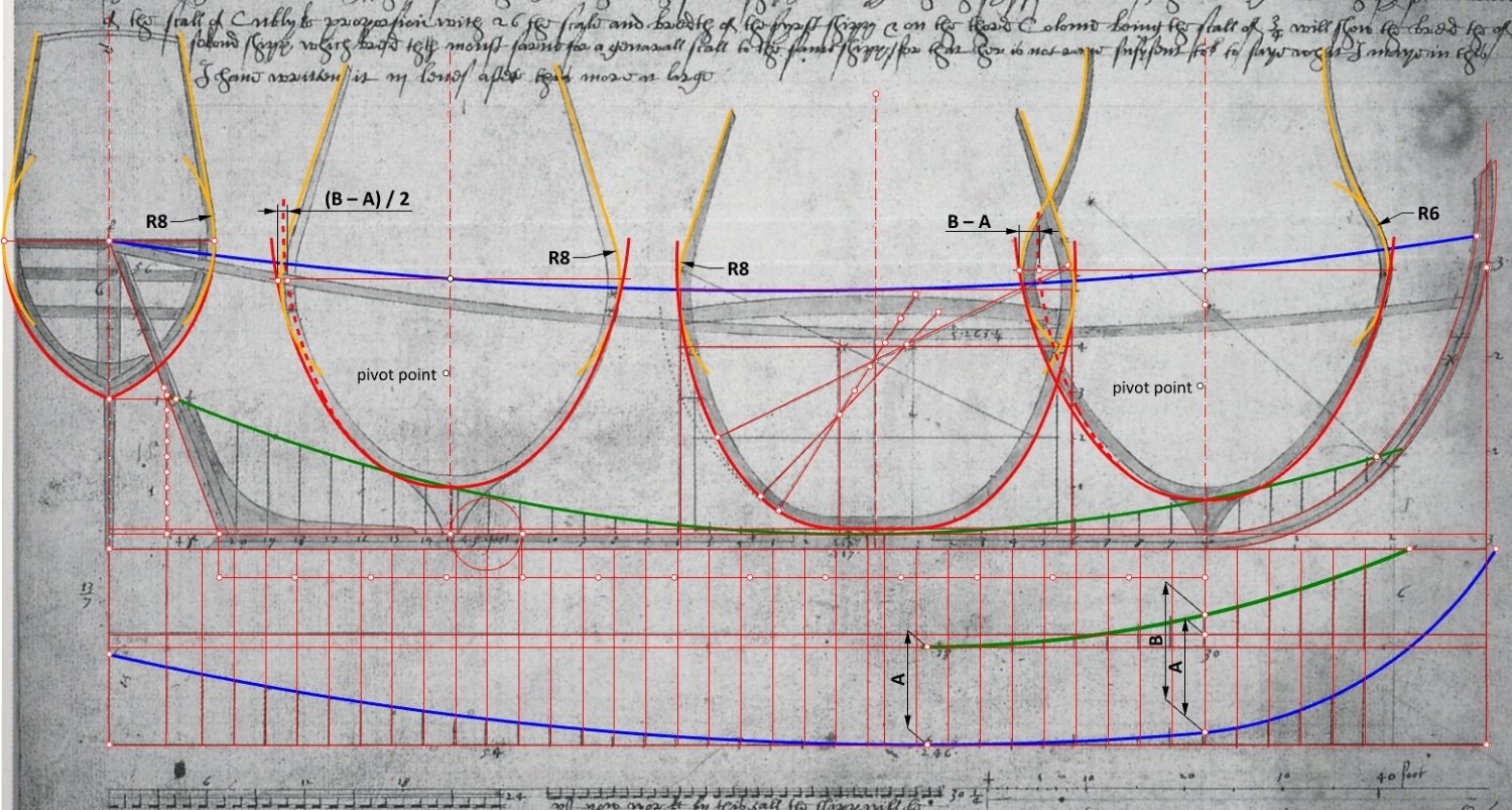
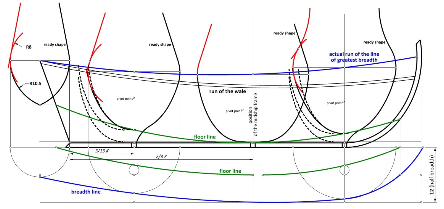
First, it should be said that the true line of greatest breadth was not drawn on the profile view or is invisible on the copy I am using. However, it could easily have been reconstructed thanks to the drawn profiles of the three frames in the original plan. This is the arc connecting the top of the sternpost to the quadrant point of the stempost, passing through the level of the greatest width of the frames. The accompanying drawing shows, in particular, the formation of the two quarter frames. The dashed lines show the successive positions of the futtock mould, moved vertically and horizontally according to the floor line coordinates, and then rotated to the point of contact with the arc of the greatest breadth. All the other frames in between the quarter frames could have been designed and constructed in exactly the same way, prior to their actual assembly into the hull under construction. The hollowing curves at the bottom of the frames have a rather careless character of quickly drawn single arcs to save time.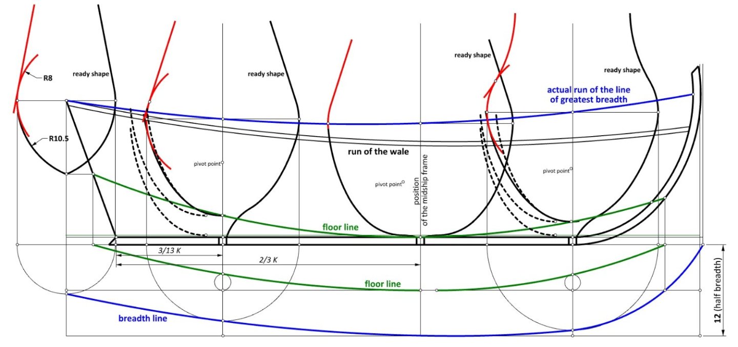
-
Mathew Baker's early concept of ship hull design, ca. 1570
Waldemar replied to Waldemar's topic in Nautical/Naval History
Okay. I guess all the design ambiguities have been recognised, despite the lack of appropriate commentary on this drawing in the manuscript. What follows is a reconstruction of the main frame, featuring two details that have not yet been recognised or convincingly explained in modern works on early English ship design. Firstly, the profile of the main frame in the drawing is slightly wider than the design breadth of the ship, but the quarter frames are already of normal width, in accordance with the plan view. The same phenomenon can be also observed in some other early ship draughts. This is due to the specifics of draughtsmanship and is a kind of a drawing convention. Tracing the frames in full-scale on the mould loft removes this inconsistency with the result of a 'normal' breadth. The second interesting detail is two adjacent arcs of the same radius. This is not a drawing mistake, as one of these arches is part of the floor timber (template) and the other is part of the futtock timber (template). This has to do with the conceptual method of shaping the profiles of the pre-designed frames very widespread in the Mediterranean. In this method, part of the frame profile was moved vertically and horizontally and then corrected by a slight rotation (fr. le trébuchement, span. joba). Baker must have learned this method during his Mediterranean travels and from Venetian immigrants. Ultimately, however, the method did not catch on in England, and no early English source work on shipbuilding describes this method.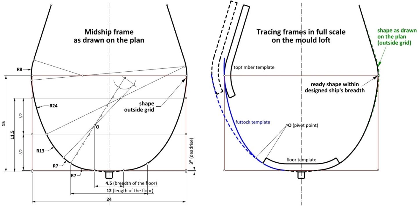
-
No comparison. I am referring to the hull lines. You can immediately see the hand of a skilled boatbuilder. 🙂
-
Mathew Baker's early concept of ship hull design, ca. 1570
Waldemar replied to Waldemar's topic in Nautical/Naval History
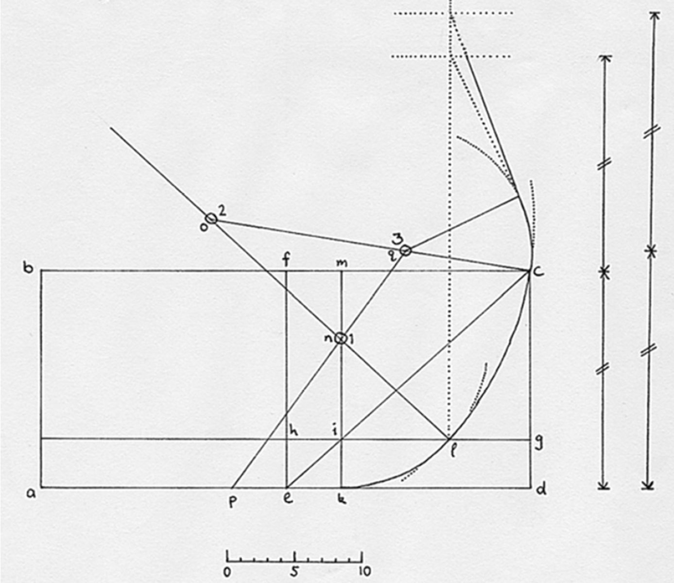
And there is no need to wait. The geometric construction of the midship mould on page 35 of the manuscript has already been explained by Johnston Stephen in Mathew Baker and the Art of the Shipwright, 1994. It is different from the midship mould of the ship plan I am analysing, so it cannot be used in this reconstruction: Figure 3.6. Fragments, p. 35 (redrawn). The diagram is a simplified version of Baker’s drawing. There are many more inked and scribed lines in the original, as well as numbers for the calculation of areas. In this example of Baker’s procedures for drawing the midship mould, breadth and depth are given as 36ft and 16ft respectively. dg = 1/5 ed. With eh = dg, draw gh. Then draw ec, cutting gh at i. Through i draw mk perpendicular to ed; ek is the floor for this half of the mould. Mark point l on gh such that hl = 2/3 gh. The first centre n is on mk and has its arc passing through k and l. Extend line ln beyond n; the second centre o is found on this extended line and its arc sweeps from l to c. To find the third centre, first mark the other half of the floor with p. The third centre q is at the intersection of oc and pn (extended). Baker then draws the upper futtock in three different ways.
-
Mathew Baker's early concept of ship hull design, ca. 1570
Waldemar replied to Waldemar's topic in Nautical/Naval History
In fact, I already have the main frame from this plan worked out. But in this particular case things are both more interesting and more complicated than just drawing it out. You'll see. The point is also that I intend to do much more with this historic drawing than has been done in all the modern works to date. -
Mathew Baker's early concept of ship hull design, ca. 1570
Waldemar replied to Waldemar's topic in Nautical/Naval History
Who came up with this strange hypothesis? And what details contained in the text of the manuscript concerning this particular plan do you have in mind? -
Mathew Baker's early concept of ship hull design, ca. 1570
Waldemar replied to Waldemar's topic in Nautical/Naval History
Wayne, are you referring to the Baker's drawing I am currently analysing? -
Mathew Baker's early concept of ship hull design, ca. 1570
Waldemar replied to Waldemar's topic in Nautical/Naval History
The next step is to recreate the lengthwise division of the hull for individual frames (room & space). The original division has not been made in an overly precise manner. However, for the aft section of the hull (i.e. behind the midship frame) the intended spacing had to be 1 foot 11 inches. For the fore section I have chosen the same spacing, but it is also possible to have a slightly different spacing where one of the lines coincides with the geometric start of the keel, as seen in the original drawing. Source works leave not the slightest doubt that the different spacing could have been used independently for the aft and fore sections of the hull. In practice, any rather small difference seemed to make little difference. It is also noteworthy that the division in both directions started not from the midship line, but from the corresponding surface of the floor timber. This means that the midship frame was to be made up of one floor timber and four futtocks, two to each side.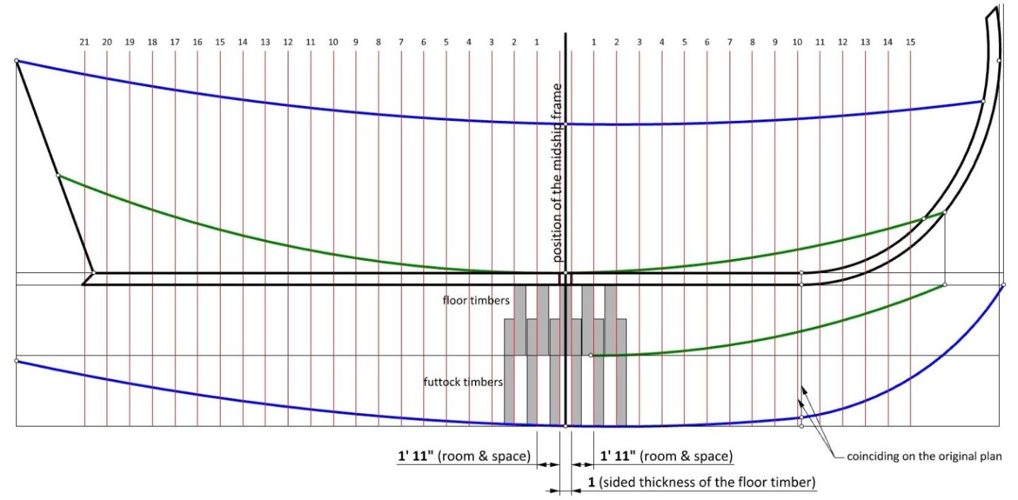
-
Mathew Baker's early concept of ship hull design, ca. 1570
Waldemar replied to Waldemar's topic in Nautical/Naval History
It seems that this observation is perfectly in line with what has been already written about hollowing curves (deadrise) in my thread on Sutherland's hull design methods. Luckily, no need to randomly guess at the particular method employed by Baker, as all the determining factors are already clearly seen on his draught itself. -
Mathew Baker's early concept of ship hull design, ca. 1570
Waldemar replied to Waldemar's topic in Nautical/Naval History
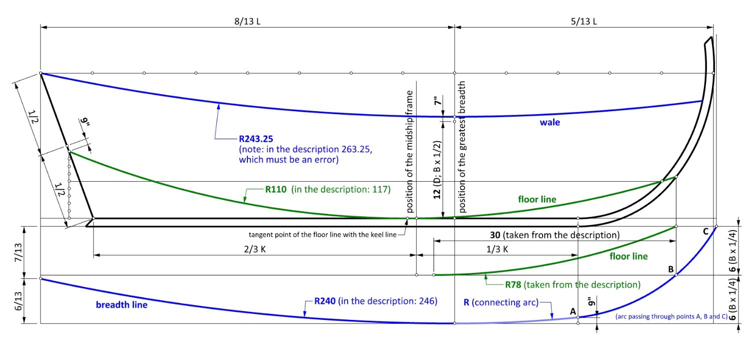
Before we go any further, I am posting a corrected sketch of the one shown in my post #8. As it turned out, the rising line of the floor (i.e. that in the profile view) was also constructed as a single arc, from bow to stern. This meant that its tangent point with the keel line fell slightly behind the midship frame (shown on the sketch). Alternatively, when drawn as passing through the three points (on stempost, sternpost, keel/midship frame intersection), it slightly cut the keel line. In practice, however, there is little dimensional difference between those two variants. I have sometimes given two values when dimensioning the same element. The second value, given in brackets, is written on the original plan, and is usually not quite accurate. Now it is perfect.
-
Mathew Baker's early concept of ship hull design, ca. 1570
Waldemar replied to Waldemar's topic in Nautical/Naval History
Jaager, it is best to hold off formulating hypotheses and drawing conclusions until the reconstruction is complete, unless you are prepared for quite a surprise. Now it has to be said that this drawing, or generally the Baker's work, has little or nothing to do with the Dutch, but rather with someone else. But more about that later in this thread. -
Mathew Baker's early concept of ship hull design, ca. 1570
Waldemar replied to Waldemar's topic in Nautical/Naval History
Thank you for your contribution, Mark. Obviously, I don't even have a chance to fill the gap left by the two scholars you mentioned, but I will try my best to at least give a decent technical interpretation of this one iconic plan. -
Mathew Baker's early concept of ship hull design, ca. 1570
Waldemar replied to Waldemar's topic in Nautical/Naval History
Druxey, please have a look at the zoom below. My measurements show quite accurately 3 inches for the deadrise at this place.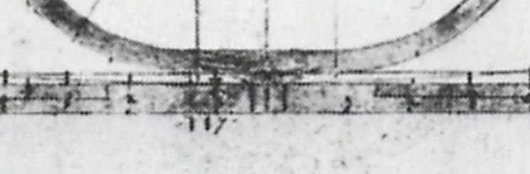
-
Mathew Baker's early concept of ship hull design, ca. 1570
Waldemar replied to Waldemar's topic in Nautical/Naval History
This is followed by the guiding rails, extremely important for this method: those of the breadth and of the floor. These rails have been drawn in the original plan in the simplest possible way as arcs of circles. The height of both ends of the floor line is quite typical for the period. In the middle this line touches the keel. Despite this, it is clear from the midship frame profile featuring a deadrise, that this is a drawing mistake or just simplification. Surprisingly, the position of the midship frame does not coincide with the greatest width of the ship.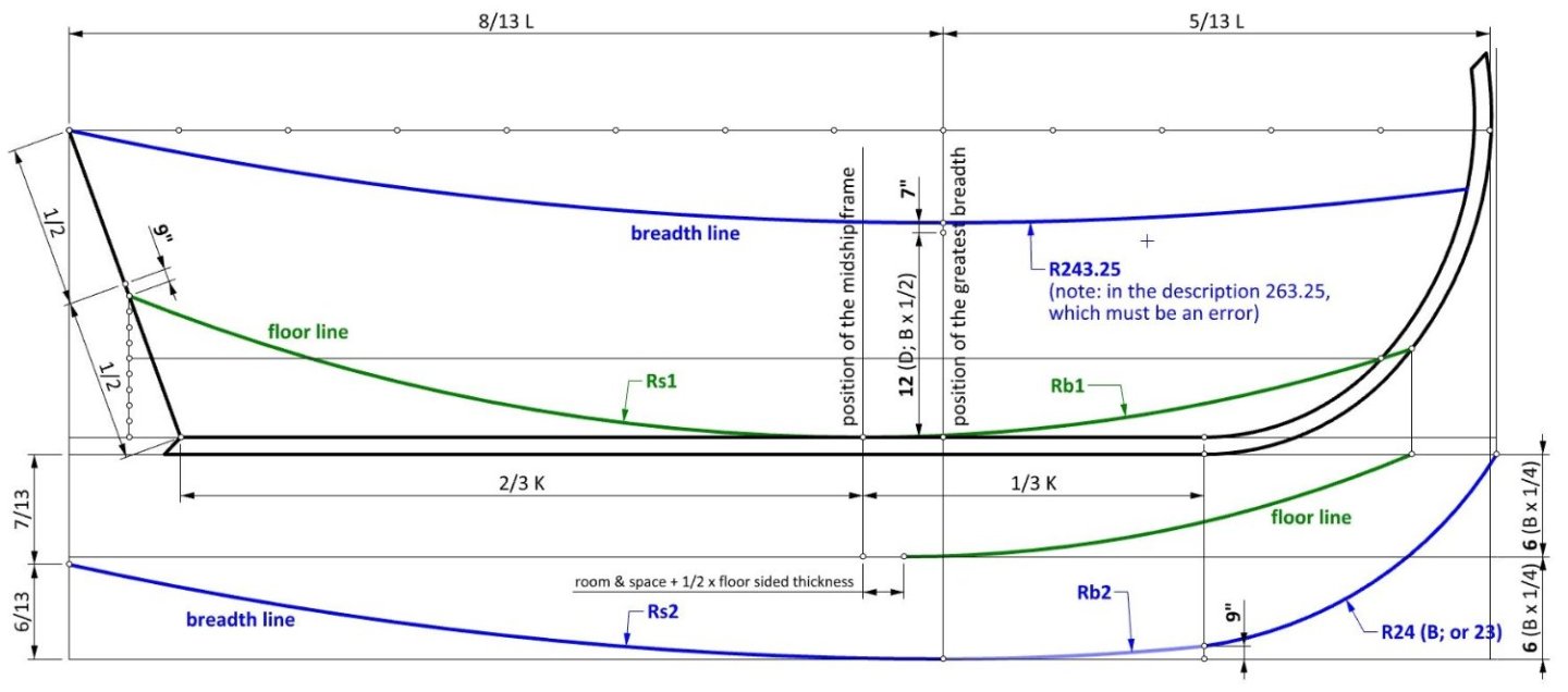
-
Mathew Baker's early concept of ship hull design, ca. 1570
Waldemar replied to Waldemar's topic in Nautical/Naval History
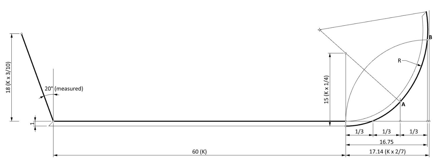
According to the most refined scale on the left-hand side of the drawing, the keel length (K) of the ship is 60 feet. The (design) hull breadth (B) is 24 feet. All dimensions are in feet, and in parentheses are given their proportions relating to other parts of the ship, as found in the most logical or expected way. The first step was to define the axial elements of the skeleton. The sketch is self-explanatory, except for the vertical of the stempost rake, which was made double to enable its drawing construction. The upper arc of the stempost is tangent to the lower arc in the point A, and passes through the point B.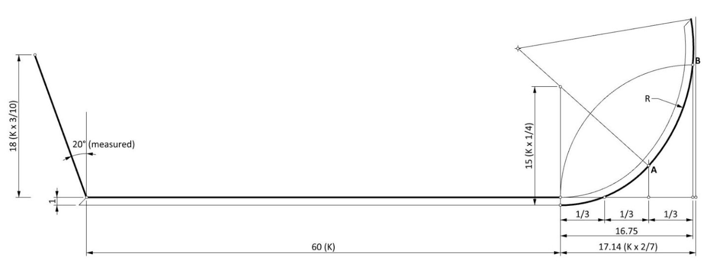
-
Mathew Baker's early concept of ship hull design, ca. 1570
Waldemar replied to Waldemar's topic in Nautical/Naval History
Thank you again Wayne. Indeed, I have found most of these studies useful in my reconstructions. I now intend to actually analyze this particular plan by Baker using graphical methods. And no, there will be no comparisons to cod's heads and mackerel's tails in my reconstruction. 🙂 -
Mathew Baker's early concept of ship hull design, ca. 1570
Waldemar replied to Waldemar's topic in Nautical/Naval History
Thank you for your input Wayne, but this is why someone should finally do it, or at least attempt to. -
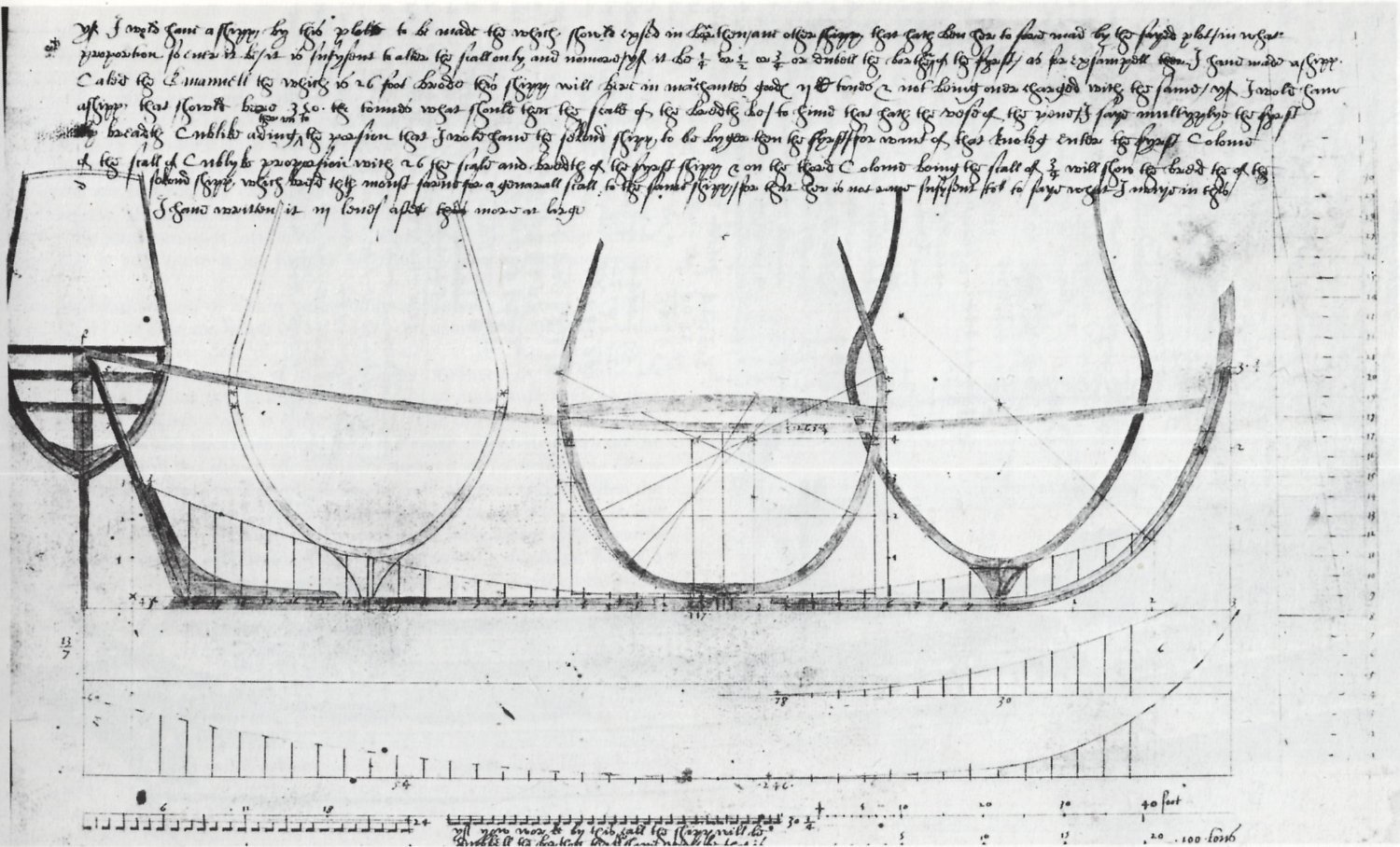
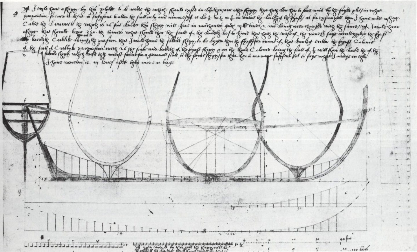
Below is a reproduction of the oldest ship plan of English origin, taken from the manuscript Fragments of Ancient English Shipwrightry by Mathew Baker (British Archives). This drawing is widely reproduced and more or less extensively commented on in numerous modern publications, but so far I have not yet encountered a detailed analysis of it, especially by graphic means. The plan is attractive for at least two reasons: it is complete in the sense that it would have already enabled the construction of the ship's hull in full scale by shipwrights. Secondly, its historical potential is considerable, as it represents a method of design different from the methods known from the later English treatises and manuals such as Harriot ms, 'Newton' ms, anon. ms 1620, Bushnell and Deane ms. Apart from other considerations, this very plan is a further indication of where to look for the roots of the methods then creatively developed by English shipwrights. The drawing contains quite a few inaccuracies characteristic of hand drawing. Reproducing errors of this kind as well as a simple redrawing misses the point, so in the following reconstruction I will rather look for the intention of the designer, trying to find as many regularities, proportions and interrelationships as possible.
-
Jesus Boat ... Rhino
Waldemar replied to tabycz's topic in CAD and 3D Modelling/Drafting Plans with Software
It must be done by manual correcting the longitudinal guides ends. This correction should start more or less equidistant from the posts to get decent results. Quite lengthy process, but perfectly possible. And, in a way, just like in real boatbuilding techniques.