.jpg.6c90d67e7e9071af590f4d4a2a8bc908.jpg)
Waldemar
-
Posts
986 -
Joined
Content Type
Profiles
Forums
Gallery
Events
Everything posted by Waldemar
-
.thumb.jpg.c6343966b029e7941df5b987d129aac6.jpg)
William Sutherland's concept of ship hull design, 1711
Waldemar replied to Waldemar's topic in Nautical/Naval History
Mark, you have made me more precise on this point: 🙂 After reading a number of works on naval architecture, I get the impression that constructing floor curves was a routine procedure used by ship carpenters. And for this very reason the early designers and writers simply did not bother with it. In one of the source works, for example, one can literally read (from memory): "the floor curves are left to the discretion of the actual builder". Sutherland was obviously aware of these common practices as well, and this is the reason for the dualism in his work. On the one hand, it was easier to draw on paper the frames of two arcs and a line, but on the other it was more convenient to use templates in the shipyard. In other words, he knew that the lines he designed would be modified by the ways used the shipyard, so he gave the method to do it more easily and correctly. This is a fortunate circumstance, because through this we learn how these floor curves were practically determined on the mould loft. -
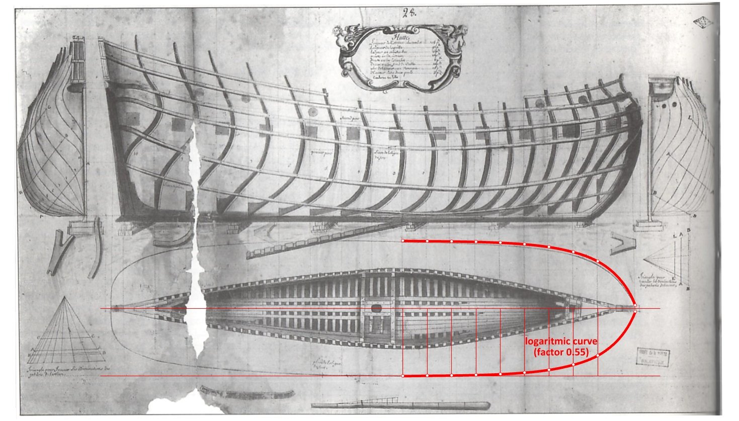
Bow shape of Le François 1683 and La Néréïde 1722
Waldemar replied to Waldemar's topic in Nautical/Naval History
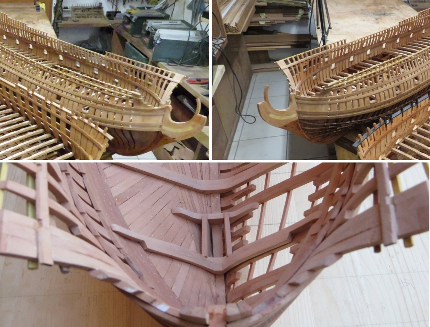
Below are the pictures of La Néréïde's model kindly provided by Michele. Now its bow lines can be better appreciated, and it happily seems that they are as perfect as on the contemporary ships' plans, samples of which are shown above in this thread.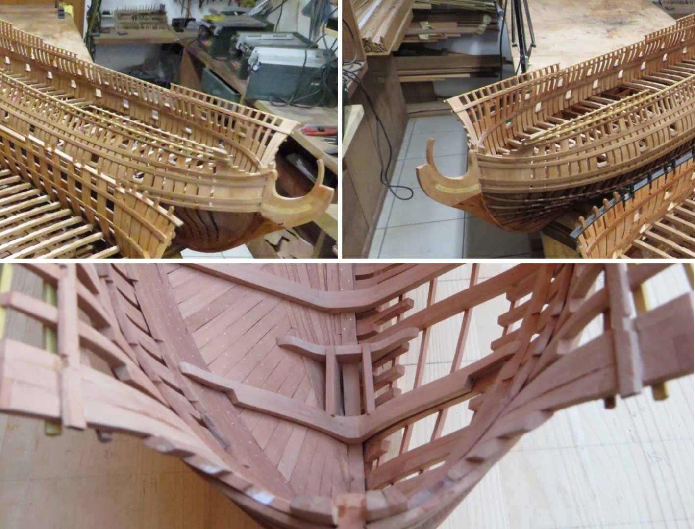
-
Sì, grazie Michele. Ora è molto chiaro che queste linee sono eccellenti e simili a quelle delle altre navi, il che mi rende felice. Yes, thank you Michele. It is now very clear that these lines are excellent and similar to the lines on other ships, which makes me happy.
-
William Sutherland's concept of ship hull design, 1711
Waldemar replied to Waldemar's topic in Nautical/Naval History
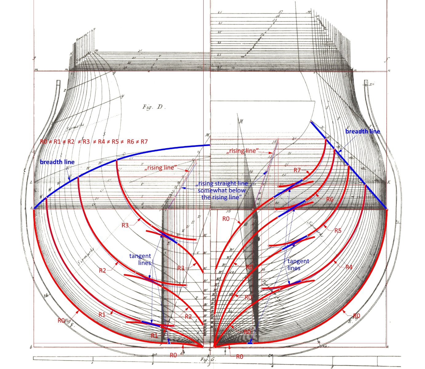
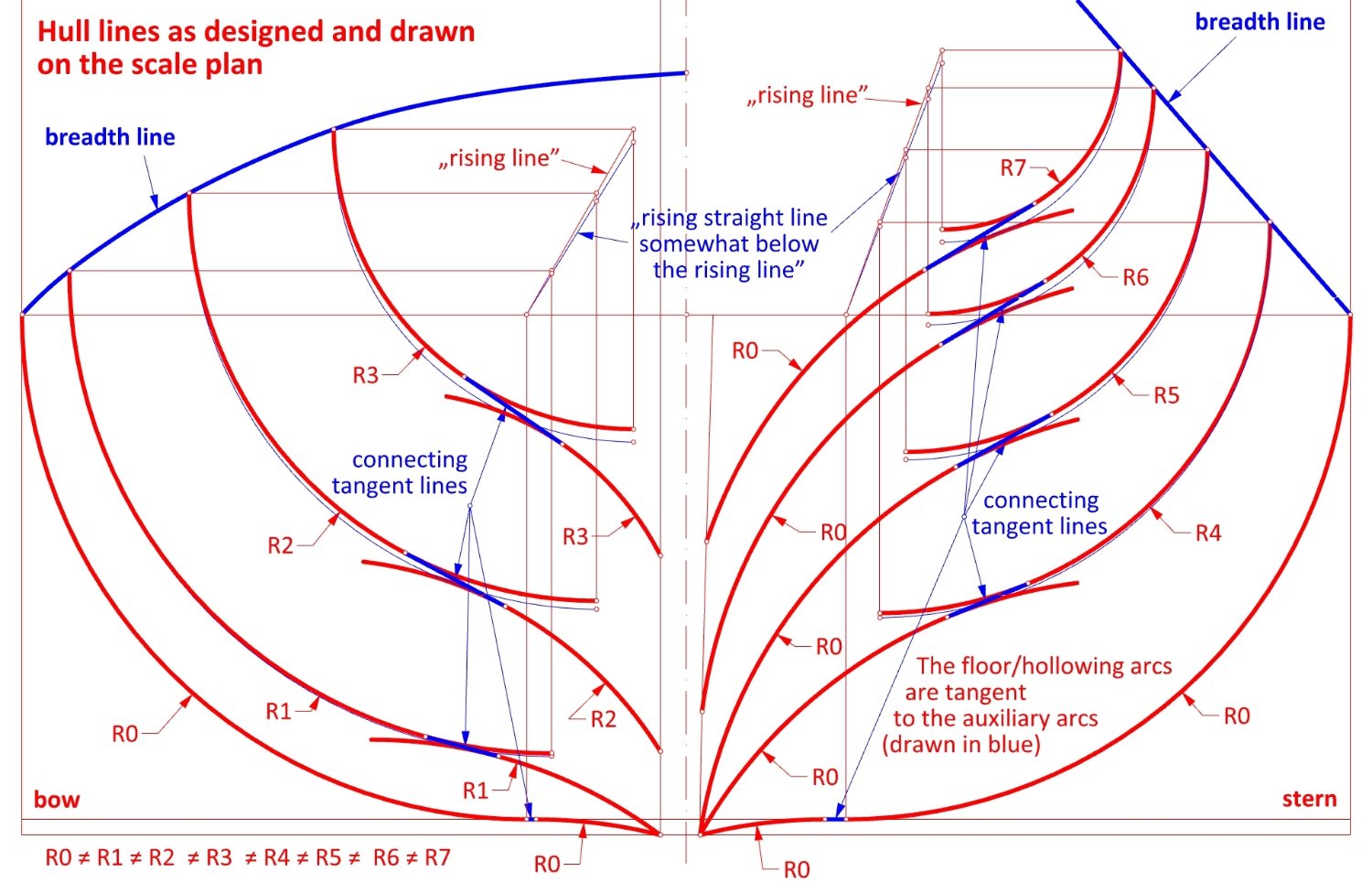
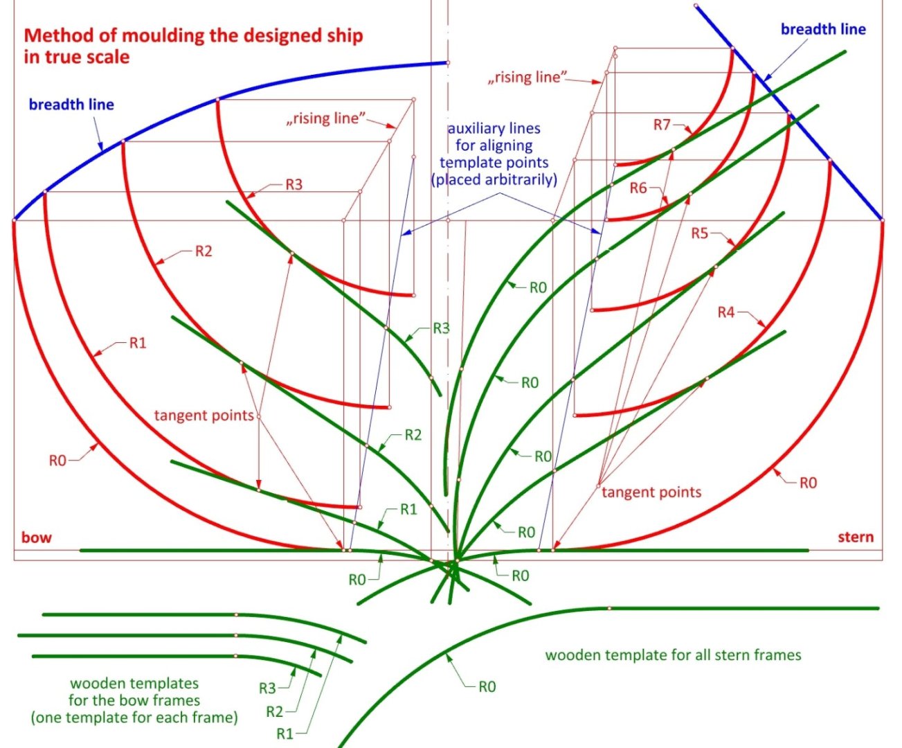
To be sure: all the above is based on Sutherland's description. It is quite obvious that he must have agreed to such a lack of precision. Wooden floor templates were to be aligned in the following way: they should pass through the point on the keel (or post), be tangent to the frame arc, and the point connecting its straight part with circular part should lie on the auxiliary line (drawn in blue in the diagram). All of this is shown in the third diagram above. Quite tricky, yet unambiguous. -
William Sutherland's concept of ship hull design, 1711
Waldemar replied to Waldemar's topic in Nautical/Naval History
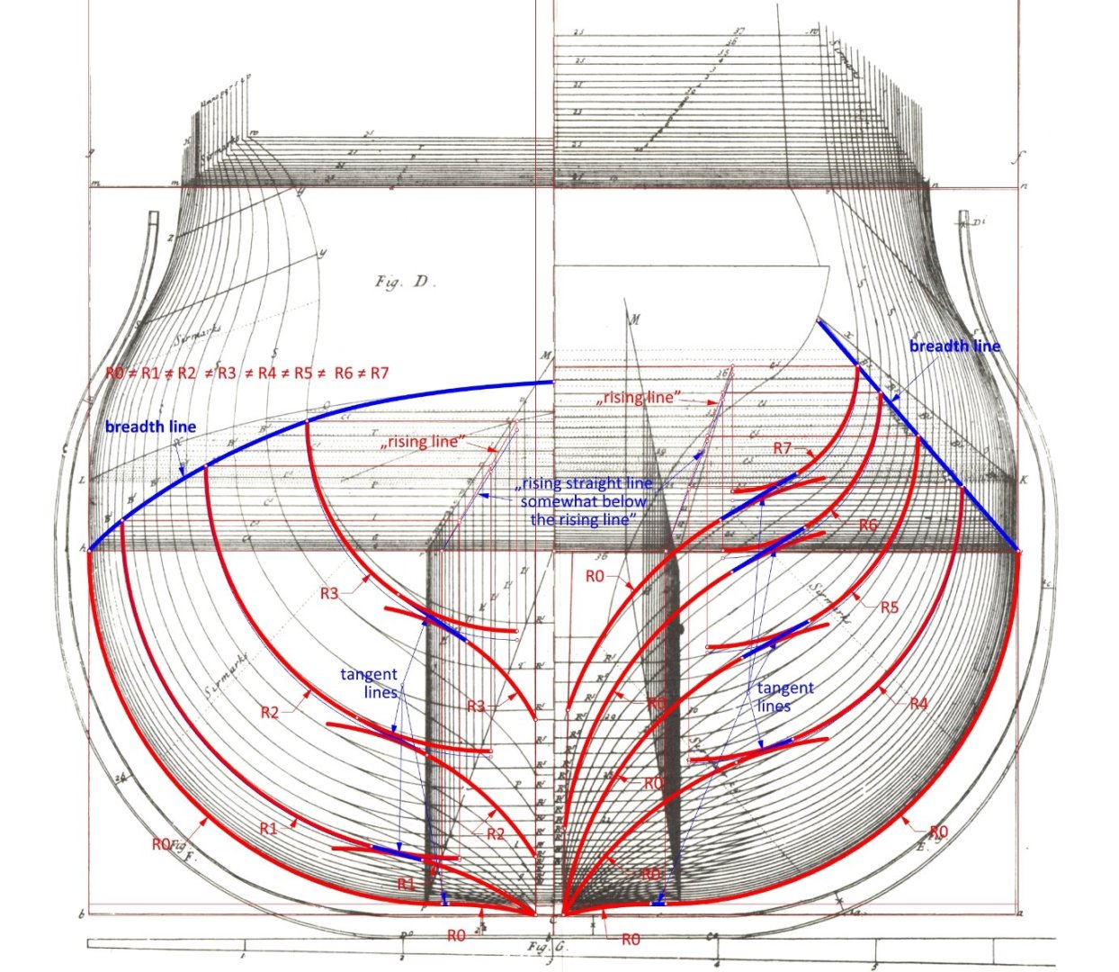
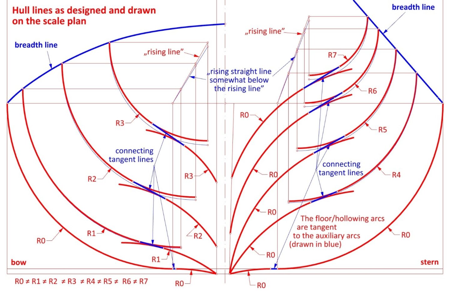
This is perfectly correct. "Connecting tangent lines" should rather be read as "Connecting lines tangent to two arcs". This was just a mental shortcut to keep the description as compact as possible. Sorry. In the diagram below a possible unintentional modification of the frame profiles in the process of actual construction is visually shown, more as a matter of showing the phenomenon itself, rather than its specific magnitude, as this effect could have been reduced by placing auxiliary (guiding) lines in better spots. Either way, the problem of constructing the floor lines was invariably treated in the early works on naval architecture at the most as secondary or not at all, and the Sutherland's description is perhaps the first to deal with it clearly enough.
-
William Sutherland's concept of ship hull design, 1711
Waldemar replied to Waldemar's topic in Nautical/Naval History
-
Redoing Oseberg
Waldemar replied to KrisWood's topic in CAD and 3D Modelling/Drafting Plans with Software
Bravo! -
Grazie per questa fotografia. Le linee di prua di La Néréïde si vedono molto bene. Perfetto. Thank you for this photograph. La Néréïde's bow lines can be seen very well. Perfect.
-
Why not stop building the model at this stage? 🙂 Such beautiful shapes...
-
I have the irresistible impression that it is your model that most resembles the originals. More so than those with perfectly smoothed lines from the age of computers and industrial robots.
- 63 replies
-
- 4
-

-

-
- Finished
- Khufus Solar Boat
- (and 1 more)
-
William Sutherland's concept of ship hull design, 1711
Waldemar replied to Waldemar's topic in Nautical/Naval History
This is actually a series of publications: The Mariner's Mirror Volume 107, 2021 - Issue 2 A Restoration Yacht’s Design Secrets Unveiled: An examination of a ship model with reference to the works of William Sutherland Effie Moneypenny & David Antscherl Pages 164-187 The Mariner's Mirror Volume 104, 2018 - Issue 2 A Model of the Royal Yacht Henrietta about 1679: Description and identification Effie Moneypenny & Simon Stephens Pages 172-191 The Mariner's Mirror Volume 102, 2016 - Issue 4 The Royal Yacht Isabella of 1683: Identification and principal dimensions Kelvin Moneypenny & Dorin Paul Bucur Pages 400-416 The Mariner's Mirror Volume 100, 2014 - Issue 2 The Royal Yacht Henrietta of 1679: Identification and principal dimensions Kelvin Moneypenny & Dorin Paul Bucur Pages 132-146 -
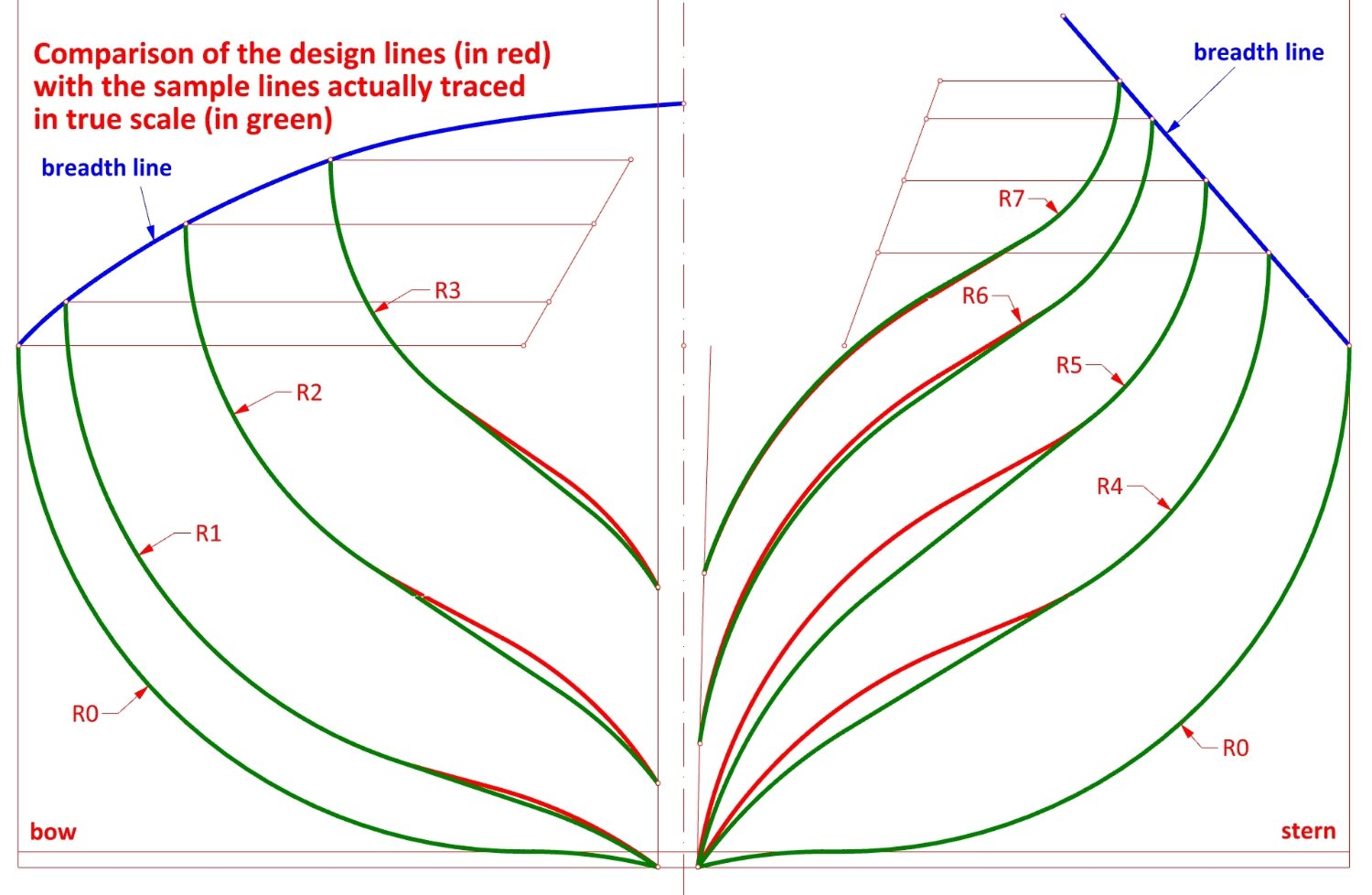
Being fresh from reading a very interesting publication on the Restoration yachts of Charles II, I looked again at William Sutherland's work, The Ship-builders Assistant, 1711, focusing on his method of shaping ship hulls. In his work, Sutherland proposes shaping ship hulls so that the submerged part of the hull takes the form of an (elongated) egg. Such a shape is called a conoid. Both the characteristic feature and result of such a form are frames with the profile of a perfect arc (connected by an additional line(s) to the keel and the posts). In addition, the radii of these arcs are different for each frame. The very idea of using variable radius arcs for different frames was not entirely new at the time. Anthony Deane (1670) had already partly used this way to construct the profile of the frames (although not in the textual description, but in his drawings), the way described in the work of Georges Fournier (Hydrographie, 1643) can also be interpreted in this way, and there is a plan of the English origin in the Russian archives, in which the arc of the greatest breadth is based on the principle of variable radius (the plan is undated, but the ship has clear features specific for the turn of the 16th and 17th centuries, in particular the square-tuck stern and the considerable rakes of both posts). Below I have shown my graphical interpretation of the method proposed by Sutherland. It should be stressed here that the original plan has some drawing anomalies and, moreover, does not quite match its textual description, so reverse engineering methods were also necessary to interpret it. As can be seen, the conoid is only the body defined by the upper arcs, while the floor curves (also called hollow lines, bottom curves etc.) were constructed by Sutherland in the conventional way. Here, too, it must be added that Sutherland chose one way of drawing the floor curves in his drawing, while in the textual description he proposed a different method for use in the actual construction of the ship in true scale, but still using a simple template made of only two parts: a line and an arc. As a result, the theoretical shapes (as in the plan) and those of the actual ship had to come out slightly different.
-
Bow shape of Le François 1683 and La Néréïde 1722
Waldemar replied to Waldemar's topic in Nautical/Naval History
Have just read the paper on the reconstruction of the hull lines of Charles II's yacht. An exciting read, but I must also admit that I would have had a few comments and my interpretation of some important issues would have been different. -
Bow shape of Le François 1683 and La Néréïde 1722
Waldemar replied to Waldemar's topic in Nautical/Naval History
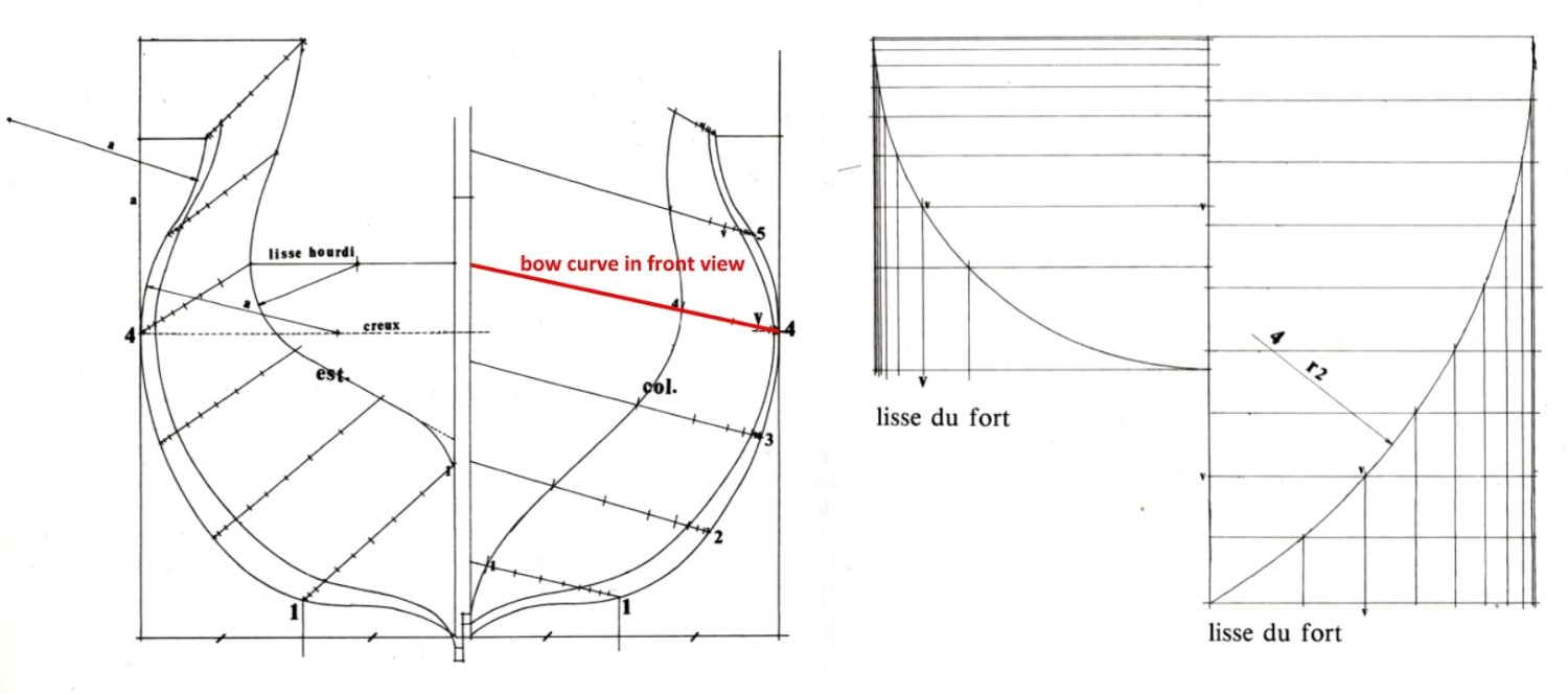
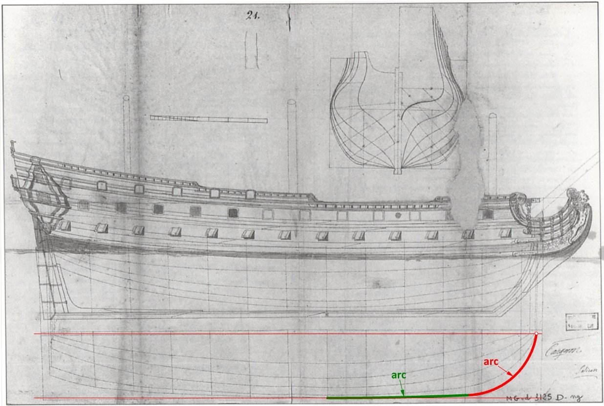
Yes, the end, but only the original plans, because I also want to show another way of constructing the bow curve shown in the work of Jean Boudriot, Les vaisseaux de 50 & 64 canons. Étude historique 1650-1780. This method must come from the 18th century French works on naval architecture (I should verify this, but I didn't for the sake of saving time). This way is quite complicated, and also for special cases where the bow curve in front view is a segment of line inclined at a certain angle, as can be seen in the attached scan below. It is shown here rather for completeness, as for all above reasons this way was not suitable for my purposes. Furthermore, the resulting curve shape is not quite decent and at the same time not the easiest to modify. The method as shown visually in Jean Boudriot's work: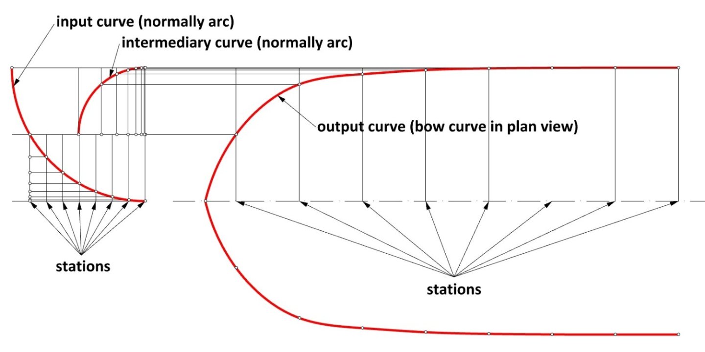

-
Bow shape of Le François 1683 and La Néréïde 1722
Waldemar replied to Waldemar's topic in Nautical/Naval History
F I N -
Bow shape of Le François 1683 and La Néréïde 1722
Waldemar replied to Waldemar's topic in Nautical/Naval History
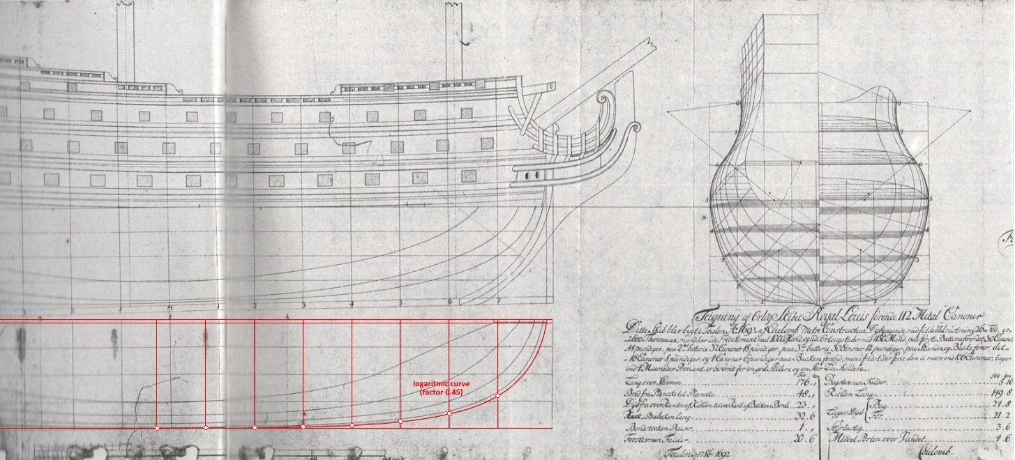
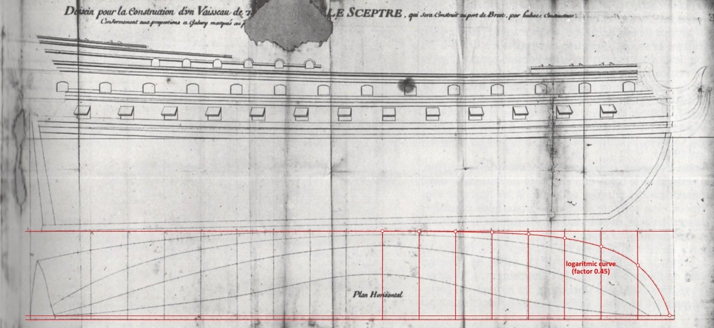
1692 – Le Royal Louis: 1720 – Le Sceptre: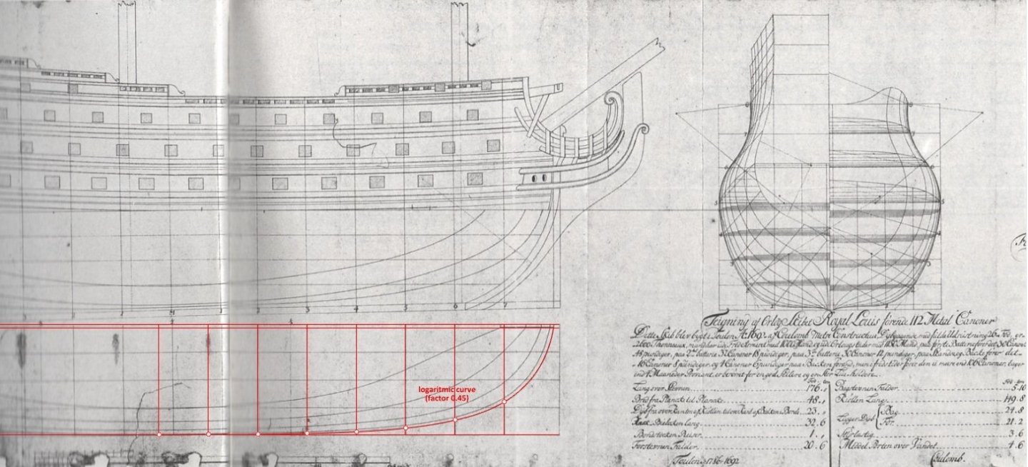
-
Bow shape of Le François 1683 and La Néréïde 1722
Waldemar replied to Waldemar's topic in Nautical/Naval History
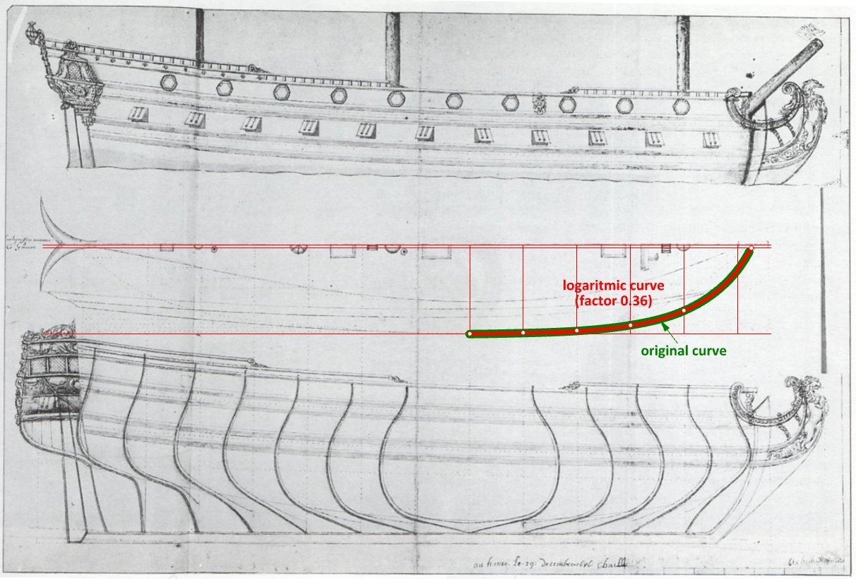
1690 – Le Laurier, 64 guns: ca. 1690 – barque longue: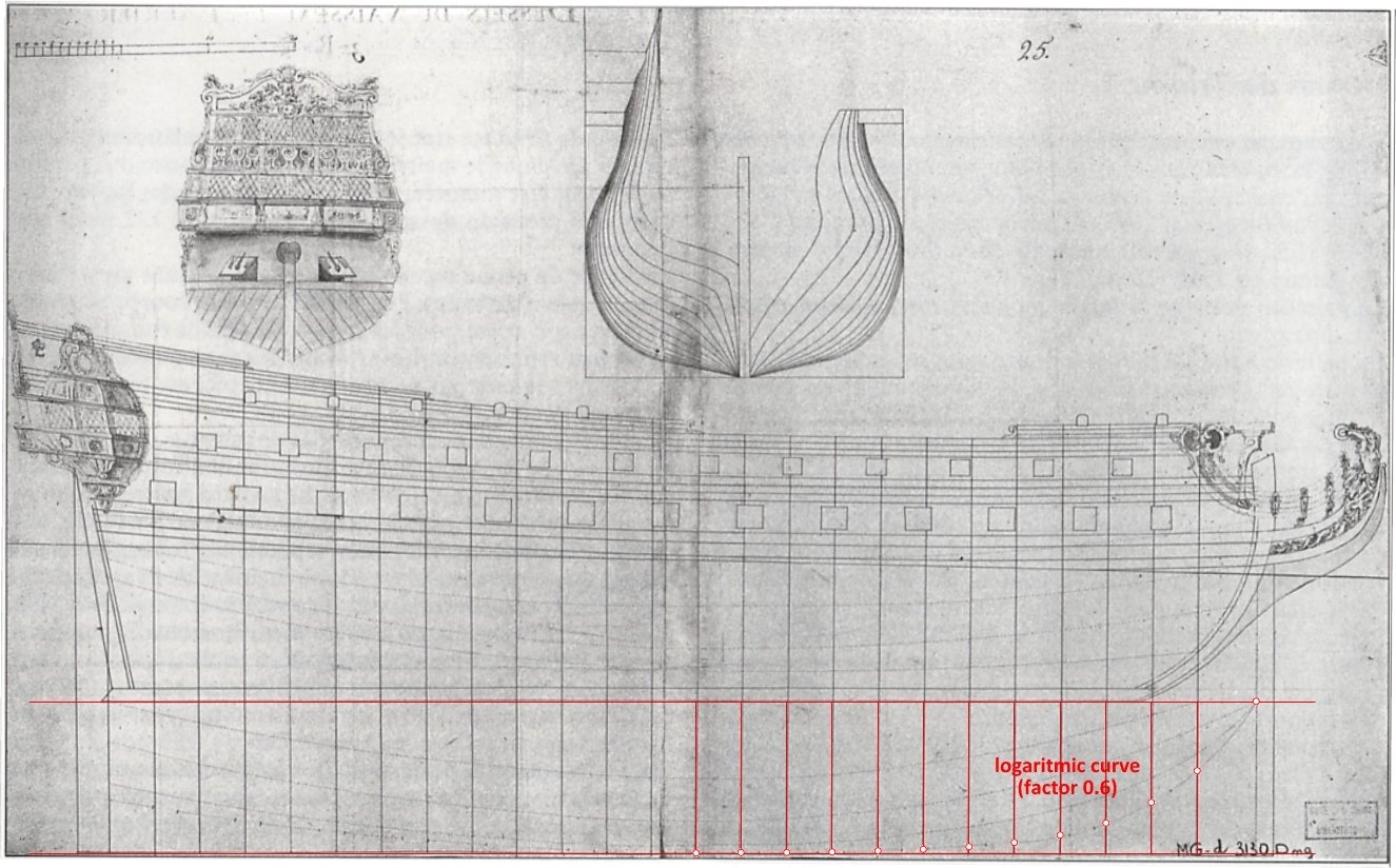

-
Bow shape of Le François 1683 and La Néréïde 1722
Waldemar replied to Waldemar's topic in Nautical/Naval History
1685 – fluit (note: distorted and uncorrected plan): 1686 – frigate of the 1st class: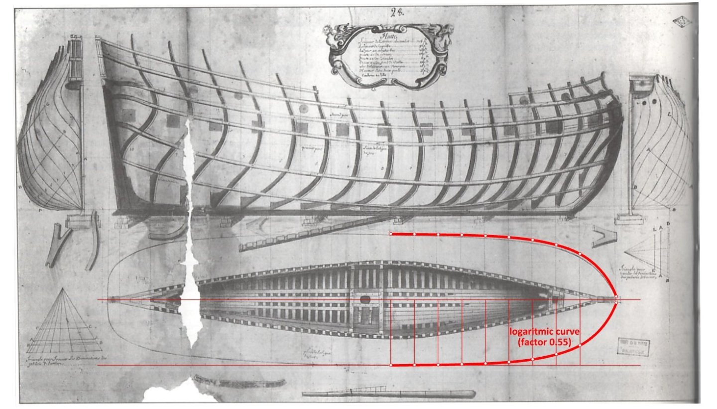

-
Bow shape of Le François 1683 and La Néréïde 1722
Waldemar replied to Waldemar's topic in Nautical/Naval History
ca. 1680 – 52-gun ship: ca. 1685 – 58-gun ship: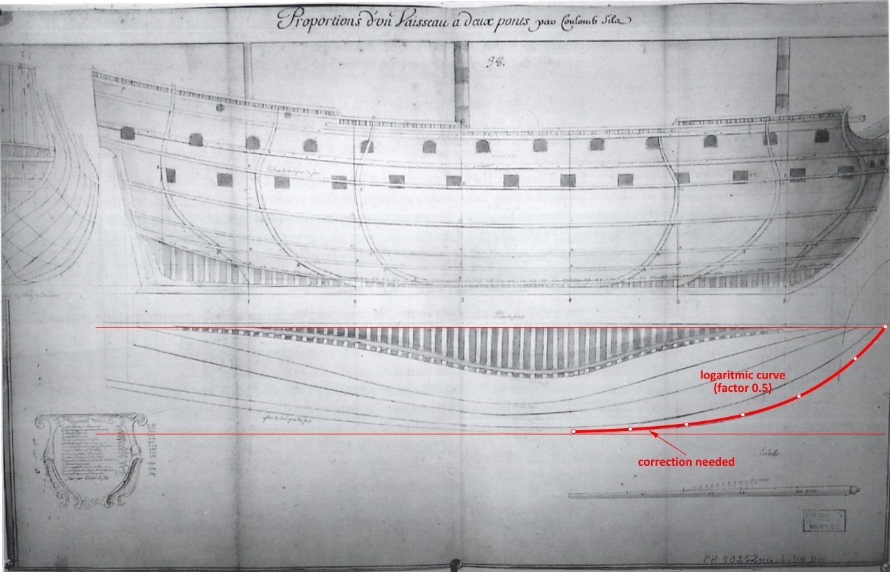
-
Bow shape of Le François 1683 and La Néréïde 1722
Waldemar replied to Waldemar's topic in Nautical/Naval History
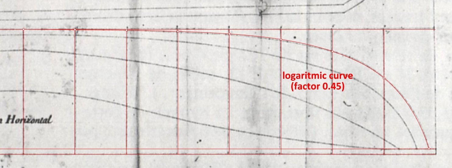
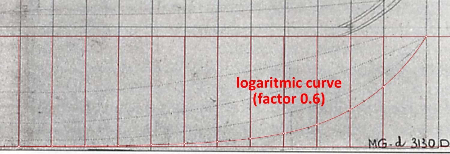
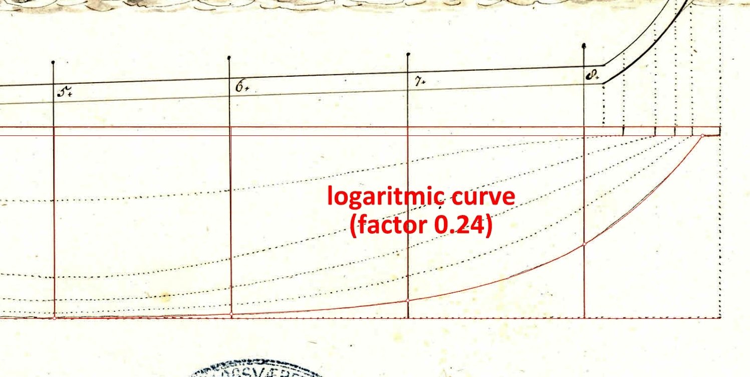
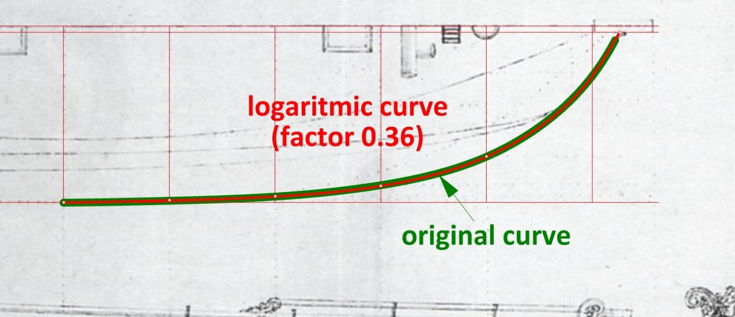
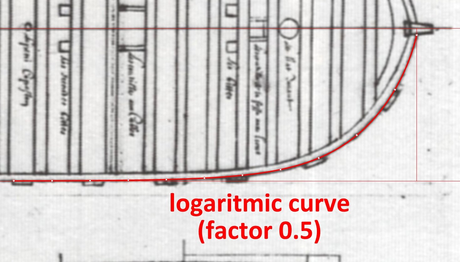
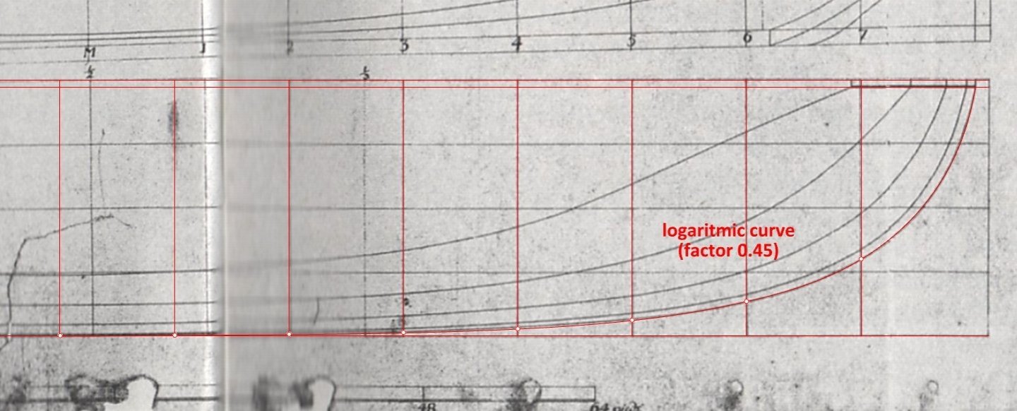
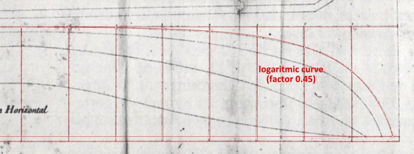
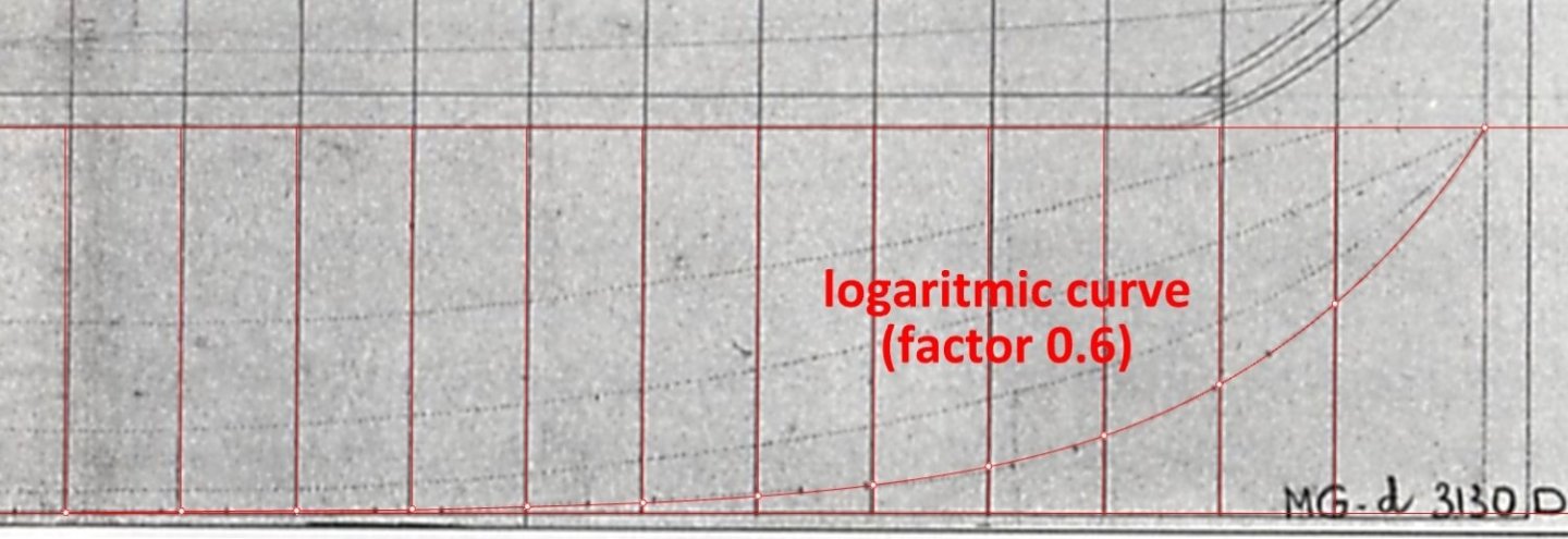
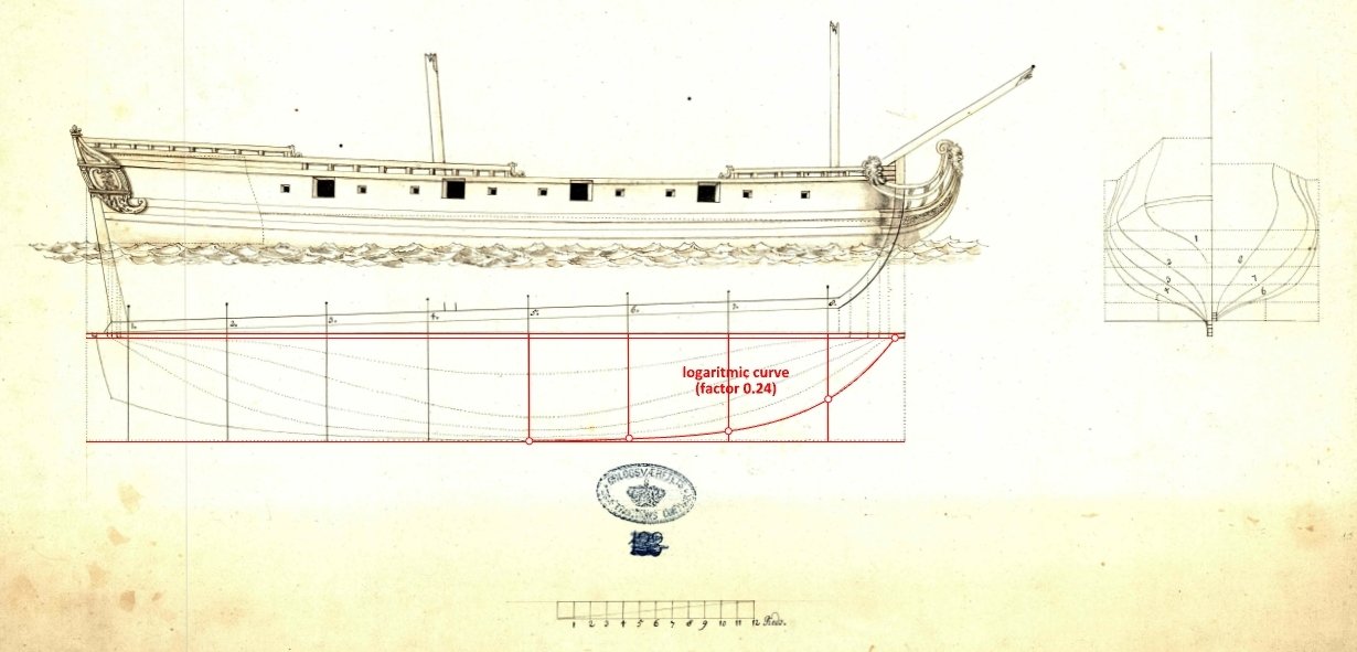
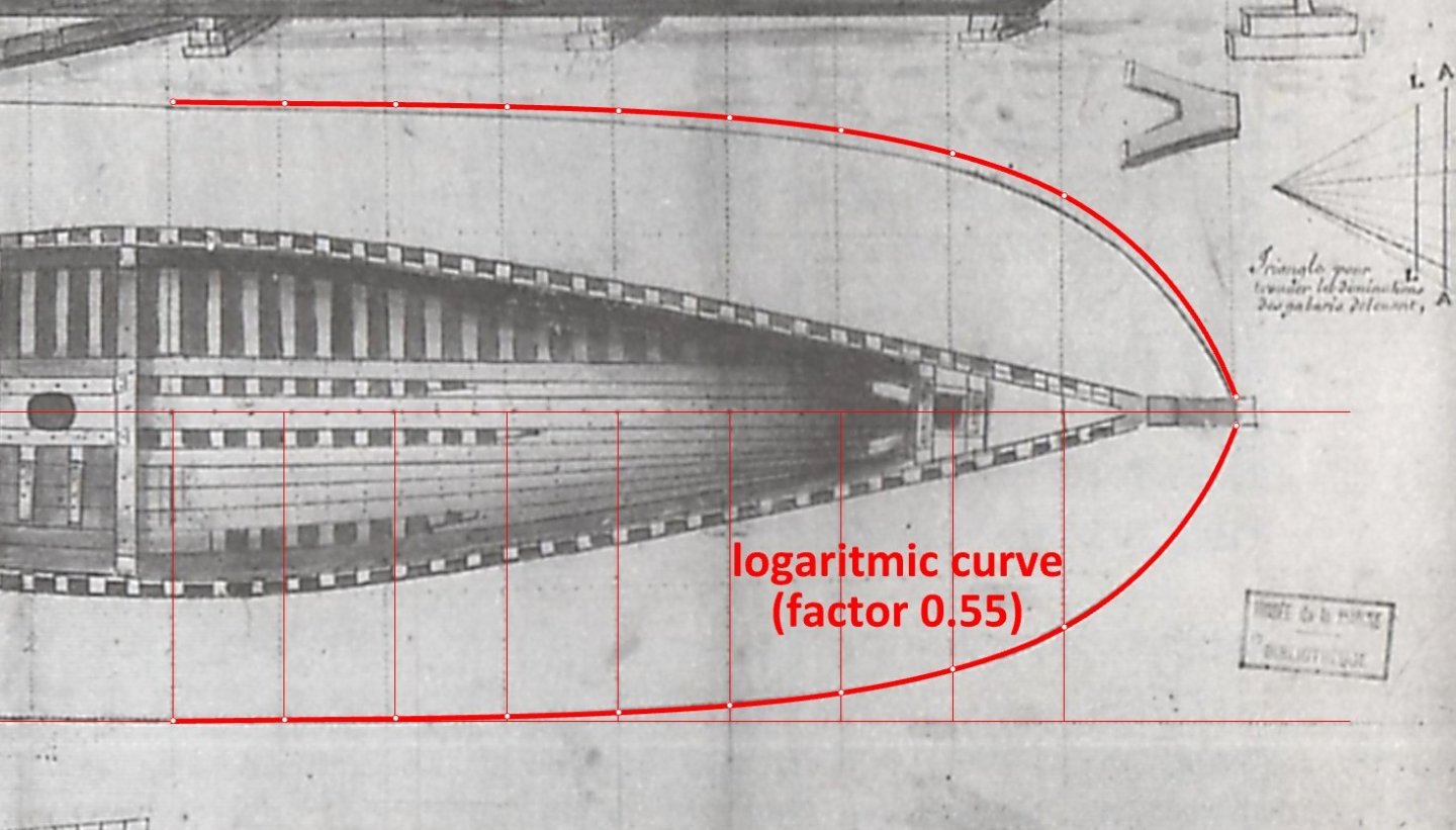
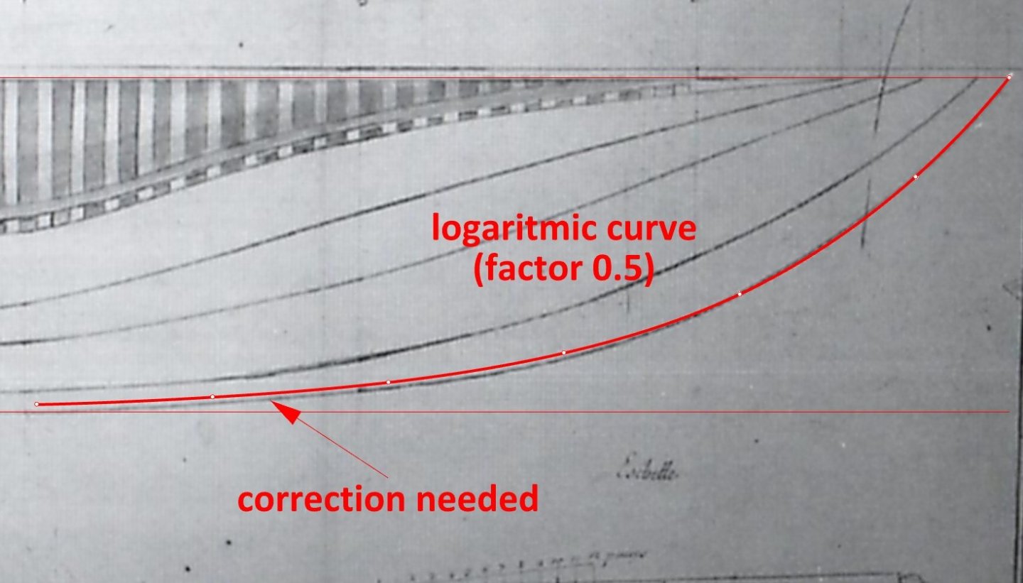
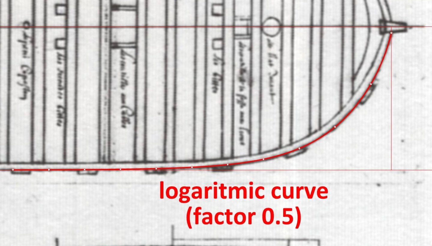
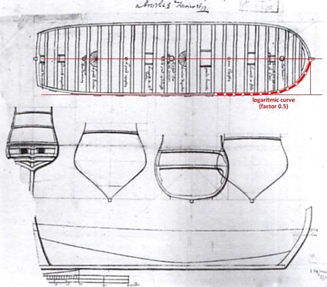
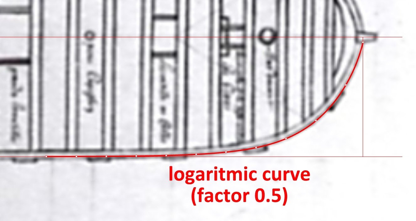
I decided to check more early plans of the French origin for the shape of the bow curve. Specifically, how often logarithmic curves were or may have been used to create them. 1679 – Project of a 1st rate ship of the line: 1679 – Le Neptune, 50 guns: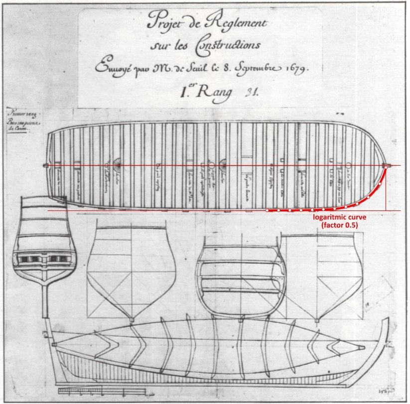
-
Bow shape of Le François 1683 and La Néréïde 1722
Waldemar replied to Waldemar's topic in Nautical/Naval History
I only have quick access to issues of the Mariner's Mirror up to 2000, but I have just located newer issues in my local library 🙂. Going there soon to pick up this article and after reading it, everything will be clear. Thanks again for this reference.
-
Bow shape of Le François 1683 and La Néréïde 1722
Waldemar replied to Waldemar's topic in Nautical/Naval History
I would have to look at Sutherland's work again, and also read the article you provided. Now, after your latest post, I am assuming that the method you refer to, gave a profile of the various frames consisting of just one arc, but of variable radii (plus, naturally, a hollow/floor curve), as in the Sutherland's work. Indeed, of extremely elegant simplicity in an engineering sense, and giving visually elegant shapes. For these reasons I wanted to use it in my reconstruction, but in the end the 'classical' method prevailed, very widespread and known for centuries for sure, in which a few templates/moulds were used to geometrically determine the contours of all the frames. That is, the radius of the respective frame arcs was constant all along the hull length (in effect, the 'hauling futtocks up/down' method). -
Bow shape of Le François 1683 and La Néréïde 1722
Waldemar replied to Waldemar's topic in Nautical/Naval History
Many thanks Druxey for pointing this publication. Methods using conoidal curves were among the most sophisticated of their era and could certainly only be used by a select few, the most accomplished designers. The approach to my reconstruction had to be quite the opposite – to find the ways as simple as possible, suitable for use by 'any' shipbuilder using non-graphic methods. Finally, I have adapted the practical method described in the extremely popular at the time work by Bushnell. Very many editions of this book emphatically testify to the fact that common builders tended to be content with such methods, which were as simple as possible. And then I mixed it with dimensions, proportions and scantlings taken from inventories, contracts and other works on period shipbuilding. -
Lovely. You are truly a professional shipbuilder.
-
Bow shape of Le François 1683 and La Néréïde 1722
Waldemar replied to Waldemar's topic in Nautical/Naval History
Both the build quality of the model itself and its lines very attractive 🙂. I must admit that I am not familiar with this publication in Mariner's Mirror, but for those interested there is also a very good chapter on ship design by John Shish in Richard Endsor's modern work, The Master Shipwright's Secrets. How Charles II built the Restoration Navy.