.jpg.6c90d67e7e9071af590f4d4a2a8bc908.jpg)
Waldemar
-
Posts
986 -
Joined
Content Type
Profiles
Forums
Gallery
Events
Everything posted by Waldemar
-
.thumb.jpg.c6343966b029e7941df5b987d129aac6.jpg) Roman, when do you expect the first sailing trials? Next year season?
Roman, when do you expect the first sailing trials? Next year season? -
William Sutherland's concept of ship hull design, 1711
Waldemar replied to Waldemar's topic in Nautical/Naval History
Okay, until then I will not accept any 'complaints' based on the brainstorm method on this interpretation, because too much has been written and is already known on this subject. 🙂 -
William Sutherland's concept of ship hull design, 1711
Waldemar replied to Waldemar's topic in Nautical/Naval History
Inserting ready graphics is quick and easy, so one more 'design' draught. This one, from the Swedish archives, is dated circa 1615, and the technical descriptions with dimensions are in English. Here, too, attempts have been made to achieve the effect of perspective. And the jump to geometrically perfect 18th century plans didn't happen overnight.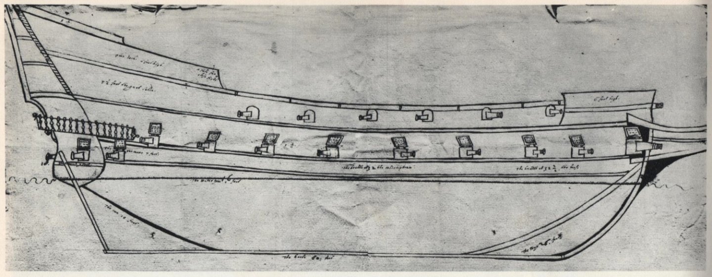
-
William Sutherland's concept of ship hull design, 1711
Waldemar replied to Waldemar's topic in Nautical/Naval History
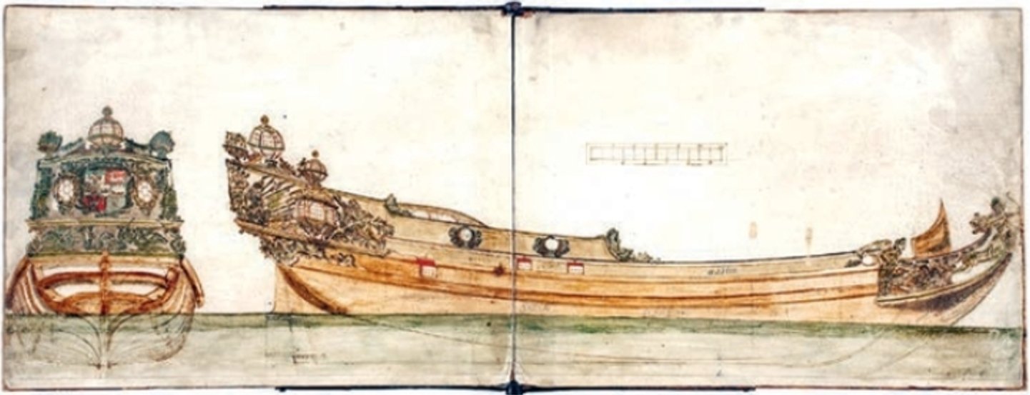
Martes, coincidentally this Swedish yacht designed by an Englishman, can be another excellent example revealing the drawing practices of the era. You can try to compare the shape of the floor/hollowing curves in the stern area as seen on the plan and on the model. Even just by eye. These are for the same ship by the same designer. -
William Sutherland's concept of ship hull design, 1711
Waldemar replied to Waldemar's topic in Nautical/Naval History
Mark: The watercolour (plan) is considered a design/proposition for the decoration of the yacht. The design set also includes a simple model made of wood and cardboard, normally unnecessary for an experienced designer himself, so rather intended to be shown to the client. It is kept in the Skokloster castle, Sweden. Martes: This looks like a bit of a clumsy attempt to gain depth in the image (perspective), and to show elements not normally visible in the profile view. The same could be true of the Swedish yacht, but here we have in addition transom beams with an arched profile. On the other hand, this curved shape could also be a way of showing the shape of these beams as seen from below. There is not yet a consistent application of standard geometric projection methods. Either way, the axial skeleton elements should, in my opinion, definitely remain in place.

-
William Sutherland's concept of ship hull design, 1711
Waldemar replied to Waldemar's topic in Nautical/Naval History
No, no, no. I would rather opt for a galley-style stern shape. A noble stern for a noble ship for noble people.
-
William Sutherland's concept of ship hull design, 1711
Waldemar replied to Waldemar's topic in Nautical/Naval History
In addition, and for comparison, another design drawing made around 1660, but this time by an equally professional shipbuilder Jakob Jakobsson Prunk of the Dutch origin. Frame profiles were not needed in this case at all, as this 18-gun frigate was most likely to be built in the Dutch fasion, i.e. by the shell (bottom-first) method. But again, look at the draughtsmanship standard (Swedish archives).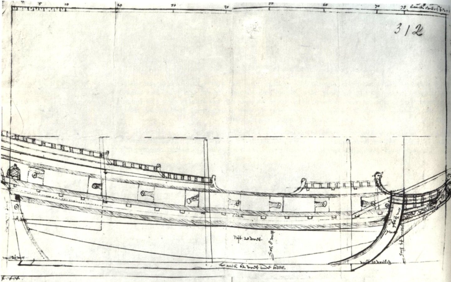
-
William Sutherland's concept of ship hull design, 1711
Waldemar replied to Waldemar's topic in Nautical/Naval History
True. As an example of a ship drawing from the 17th century, I still include below a plan of a yacht from 1665, which was built at the Götheborg shipyard by an Englishman, Francis Sheldon. This is the oldest extant ship plan in Sweden showing the profile of the frames (stern only). As you can see, the drawing standard is still far from the precise 18th century convention (Swedish archives). I will no longer carry out a reconstruction of this shape, but the frame profiles indicate quite clearly that the designer used the conventional frame-moulding method.
-
William Sutherland's concept of ship hull design, 1711
Waldemar replied to Waldemar's topic in Nautical/Naval History
In fact, I do not insist on accepting or confirming this interpretation. But the mere awareness of such a possibility might just come in handy for you while potentially inspecting some period plan. -
William Sutherland's concept of ship hull design, 1711
Waldemar replied to Waldemar's topic in Nautical/Naval History
The Danish ship Prins Christian (renamed 1673 as Christianus Quintus) was built on contract at the Neustadt shipyard. Sorry, but if the content of this thread so far is not convincing enough, it remains to refer to Sutherland's original work. I may find some more examples, but by accident rather than by deliberate search. The copy of the plan of the French ship made available is quite poor and the lines are not quite clear. Anyway, just a note here that this was a transitional period in France at the time as far as the shape of the stern is concerned and it may be some strange hybrid. Why not try to interpret this shape yourself? -
William Sutherland's concept of ship hull design, 1711
Waldemar replied to Waldemar's topic in Nautical/Naval History
I am not sure that the example with the French ship is quite relevant. This ship was built by the designer René Levasseur in 1692. By this time, the French shipbuilders were already using newer design methods, using geometrical diagonal lines, unlike the British, who were still using one frame-moulding variant or another for quite a long time. Firstly, as can be seen from the drawing, the lines of the French ship were reconstructed in the British fashion (frame-moulding), so it is certainly not an accurate representation of the hull shape. Secondly, the problem of bottom curves was solved in a completely different way in the French method, but that's another story.... -
William Sutherland's concept of ship hull design, 1711
Waldemar replied to Waldemar's topic in Nautical/Naval History
To be honest, I don't see any contradiction in our statements, and the answer to this kind of doubt is probably also simple: around the turn of the 17th and 18th centuries there was a change in drawing convention to a more precise one, with Sutherland still representing the old school. And I remind that the Danish ship was built 1665. There is no doubt that ships could have been built according to plans (with some reasonable tolerance). On the other hand, we have 'countless' examples of ships built for the Navy, especially by private shipyards, oversized by 5, 10, 15% or even more in relation to their design (largely for financial reasons), so the differences must have been counted in feet rather than in inches. These were accepted, paid for and successfully put into service. -
William Sutherland's concept of ship hull design, 1711
Waldemar replied to Waldemar's topic in Nautical/Naval History
Unfortunately, there is no indication of the experimental nature of the Danish ship. On the contrary, her very long, intensive and successful service (about 40 years) also rather proves that this is not some kind of experimental, bizarre fantasy, mostly unsuccessful. Instead, there is Sutherland's work explaining this phenomenon very convincingly. So personally, I see the Danish ship as a 'standard' vessel, just like 99.9% or tens of thousands of other vessels. I guess a good analogy is the simplistic, common way of drawing threads in modern engineering drawings, which does not show their true outline at all. Today it is common knowledge that this is just a drawing convention to save the draftsmen time, but what about the interpretation of such drawings by archaeologists five hundred years from now? 🙂 -
William Sutherland's concept of ship hull design, 1711
Waldemar replied to Waldemar's topic in Nautical/Naval History
From my observations, the simplest possible explanations and methods are usually correct. In post #9 you will find my brief interpretation of this phenomenon, and after every hull I draw I am more and more sure of it. On the surface it may seem that the method of drawing used by designers or draughtsmen is longer and more difficult, but in fact the opposite is true. If you do drawings, whether by hand or computer, you can check this for yourself. Try drawing a few frame profiles using both methods, and for this exercise you may follow Sutherland's instructions shown in this thread. You will find that it is much more difficult and longer to draw the shipyard profiles that were obtained with wooden templates – it's endless fitting by trial and error. In this light, it is clear to me that the designers actually used shortcuts to speed up the drawing. In contrast, it was much more convenient and quicker to use wooden templates in the shipyard. To put it another way, it was a kind of drawing convention, and 'everyone' knew that the floor/hollowing lines would only be finally formed on the mould loft in the shipyard. As is clear just from Sutherland's description. The shape of the ship you posted above gave me a good laugh.... 🙂 What an imagination! -
William Sutherland's concept of ship hull design, 1711
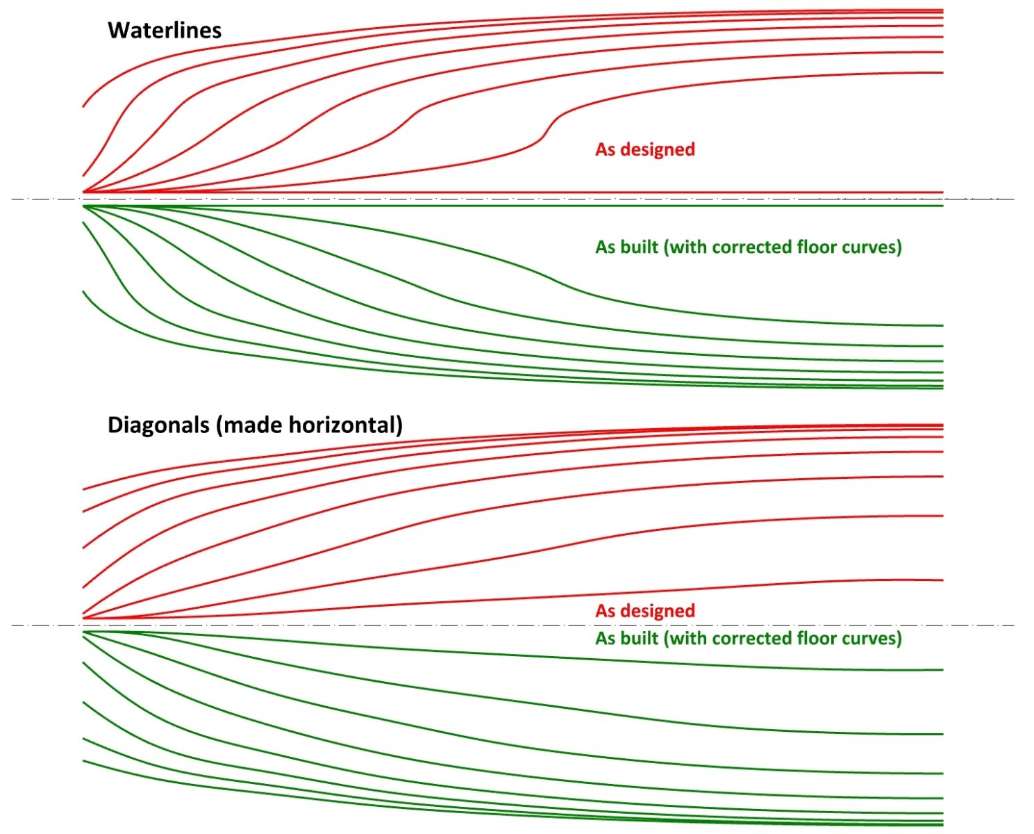
Waldemar replied to Waldemar's topic in Nautical/Naval History
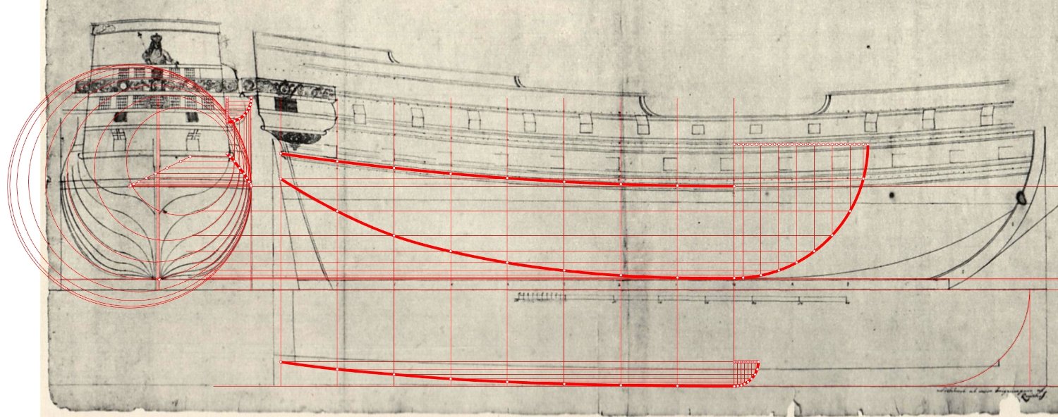
Waterlines and diagonals of the reconstructed hull section of the Danish ship. I have not made any corrections.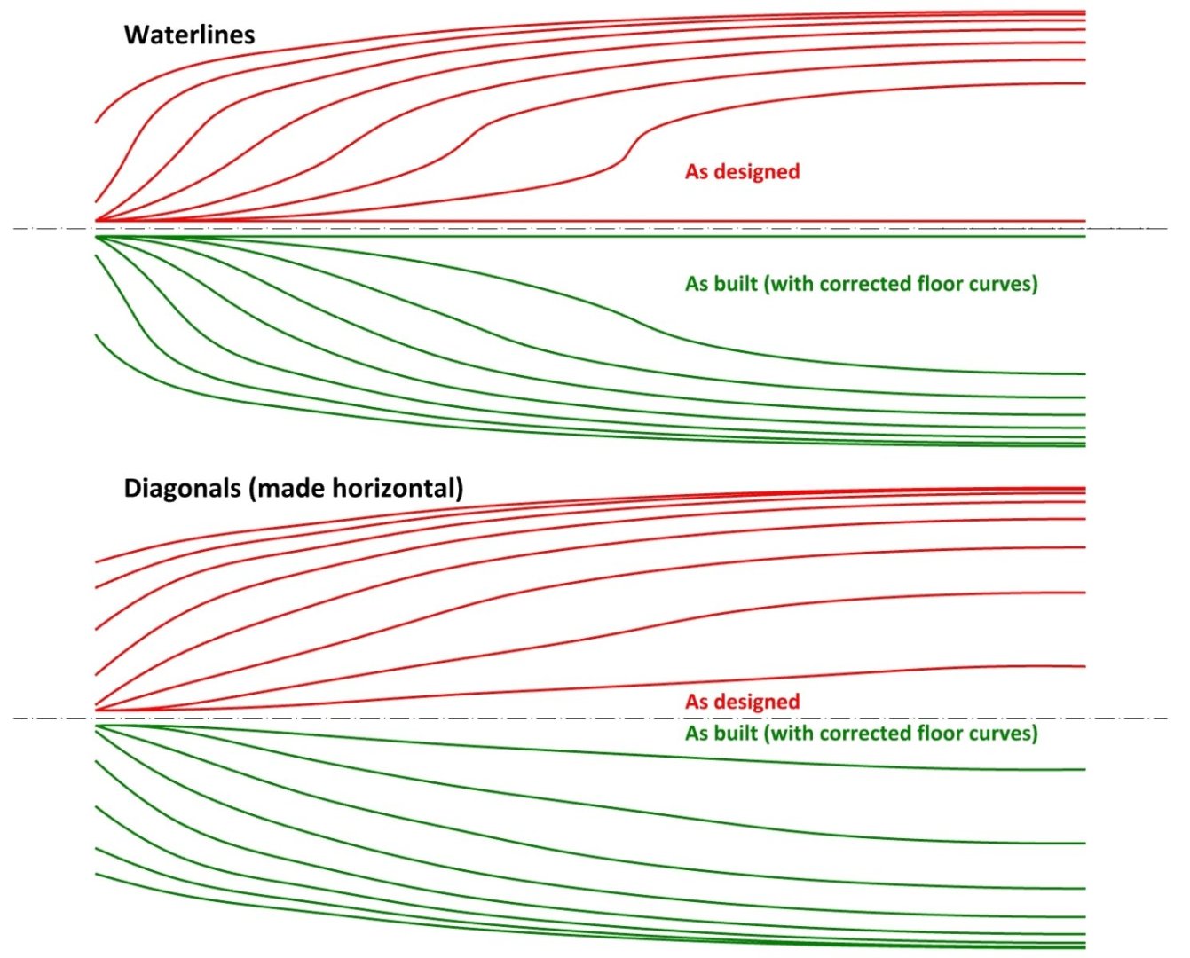
-
William Sutherland's concept of ship hull design, 1711
Waldemar replied to Waldemar's topic in Nautical/Naval History
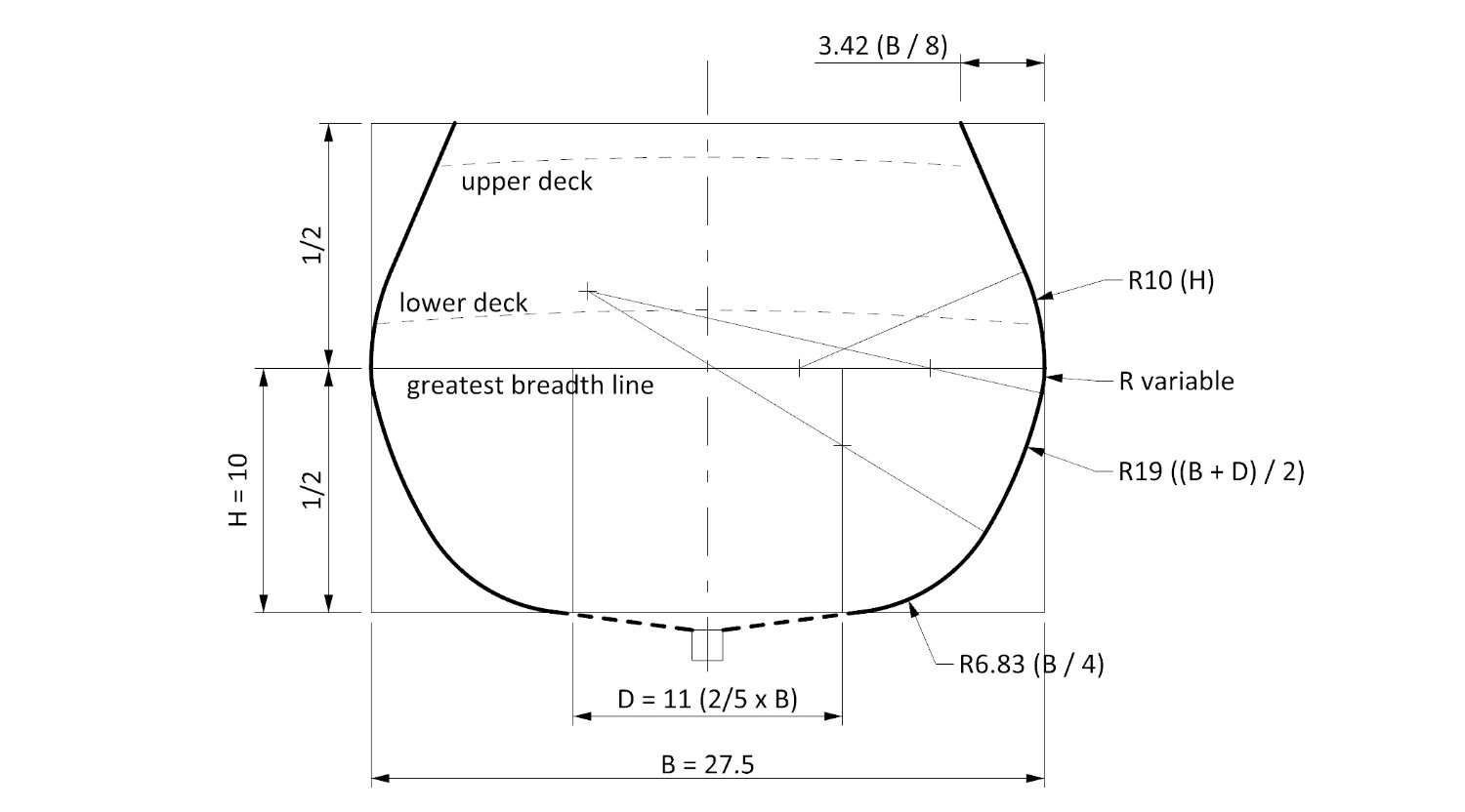
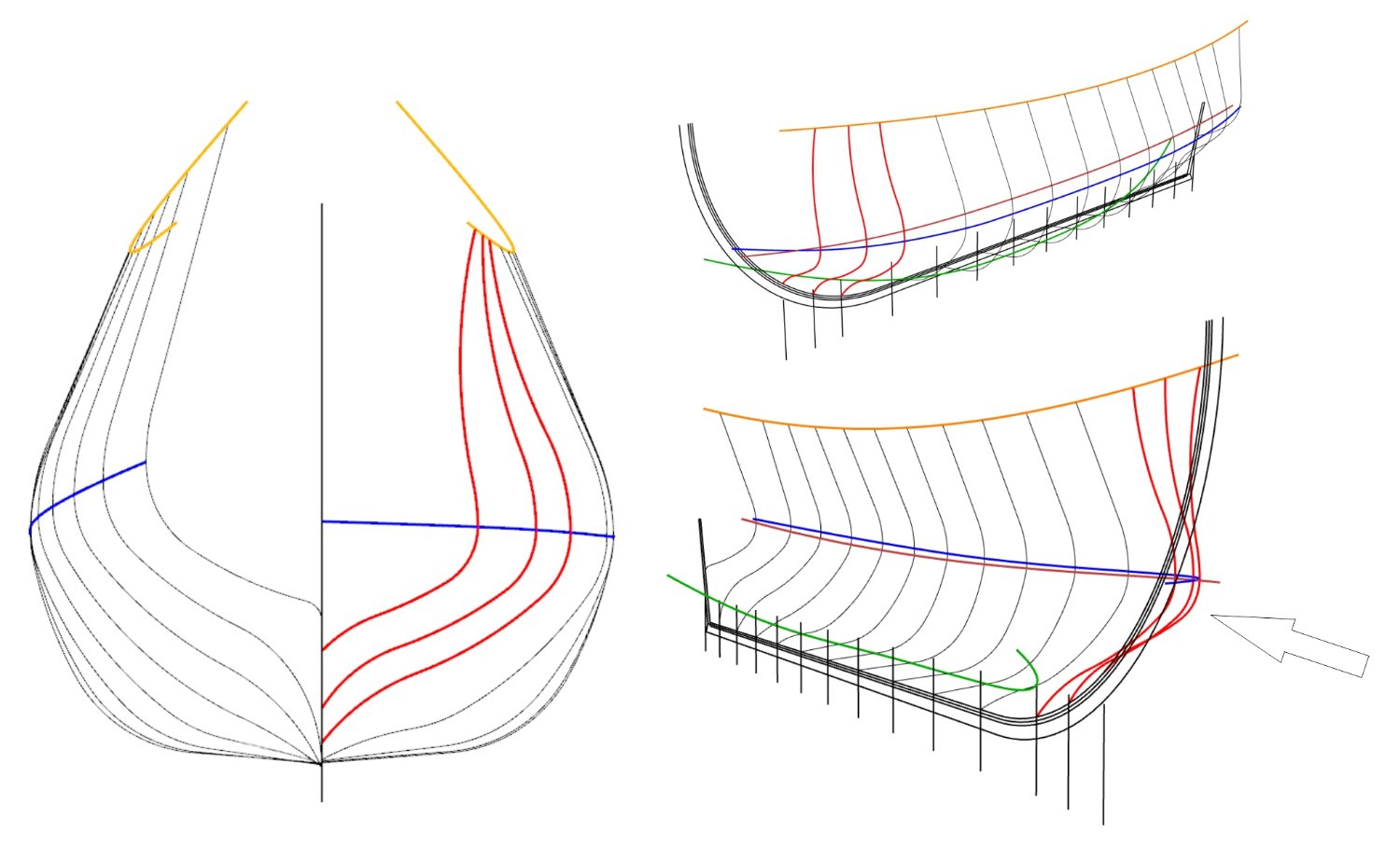
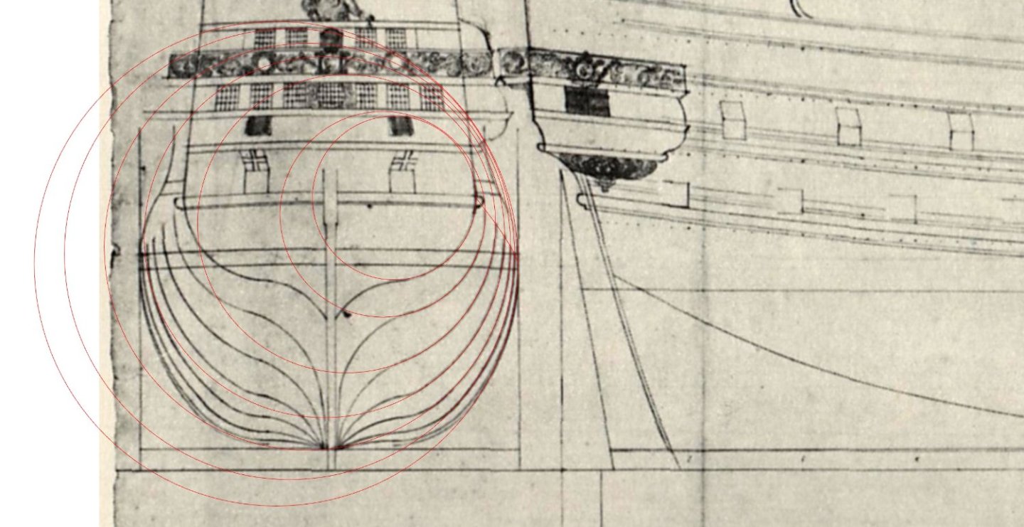
Martes, thanks a lot again for pointing me to previously unknown material from 1657. As for this ship plan from the Russian archives (Hermitage), a poor copy of it was first published in the Russian journal Судостроение 1971/08 (Shipbuilding 1971/08) in an article by A. I. Dubravin, Shipbuilding in the age of the Northern War (in Russian). This plan is described in this article as an example of a design drawing from that time, i.e. circa 1700. This is, of course, nonsense. Personally, I think they were simply brought to Russia by Tsar Peter I from his travels in western Europe. I reverse-engineered this plan a few years ago and found many of the proportions consistent with the 1620 shipbuilding manuscript. As in the example illustration below. In the process, I have also made a simple 3D model as a feasibility test.

-
William Sutherland's concept of ship hull design, 1711
Waldemar replied to Waldemar's topic in Nautical/Naval History
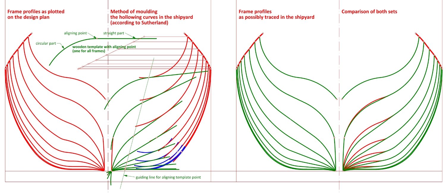
Thank you very much Druxey. To finish the job one more diagram comparing the design profiles of the Danish ship with the possible profile shapes that could have actually been traced in the shipyard (according to the Sutherland way). I have made no attempt to get these two sets as similar as possible. Now I ask myself: which set would I choose for my model or reconstruction of this ship if such an attempt were made?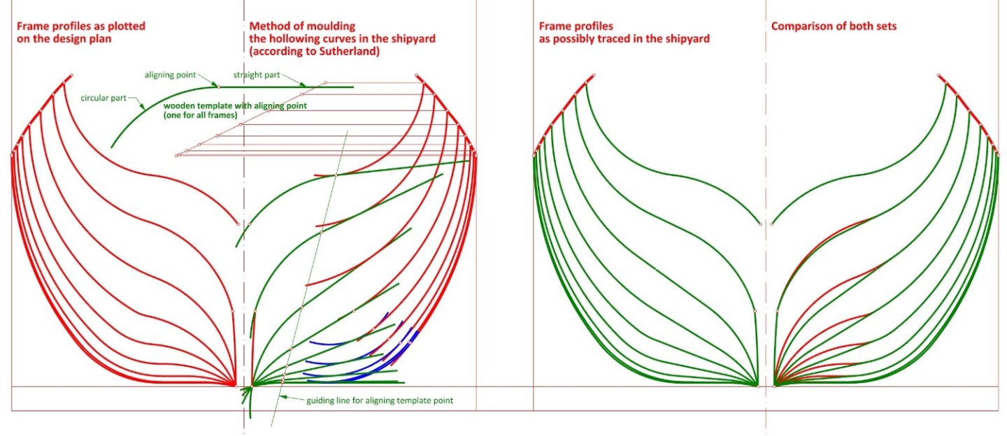
-
William Sutherland's concept of ship hull design, 1711
Waldemar replied to Waldemar's topic in Nautical/Naval History
Well, I try very hard to keep to the spirit of the age... 🙂 Many thanks to you as well, because through this very exercise I too have become more familiar with the ins and outs of period ship design. 🙂 -
William Sutherland's concept of ship hull design, 1711
Waldemar replied to Waldemar's topic in Nautical/Naval History
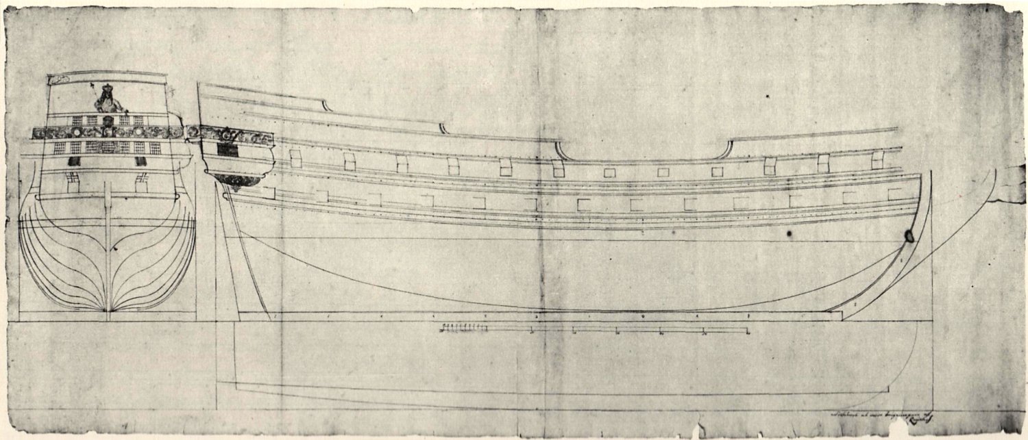
Many thanks Martes for these links, much appreciated! And you may be perfectly right about the creator of these draughts now kept in the Russian archives. Similarities to the other Balfour's draughts are striking indeed. Once, when examining just a copy of this plan in detail, I also noticed many similarities to the specific proportions, shapes and methods as described in an English manuscript from around 1620. If I had copies of the originals at the time, rather than just this poor redrawing... Anyway, the original drawing, in contrast to its poor copy, show the frame profiles as having the floor curves, so, as a replacement another draught, better suited to my narrative (from the Danish archives). It should replace the first one inserted in post #12: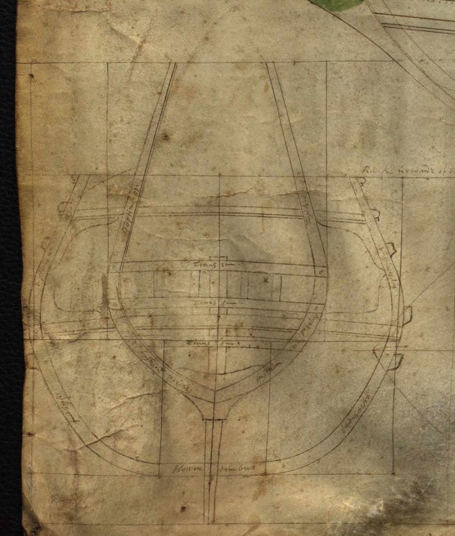
-
William Sutherland's concept of ship hull design, 1711
Waldemar replied to Waldemar's topic in Nautical/Naval History
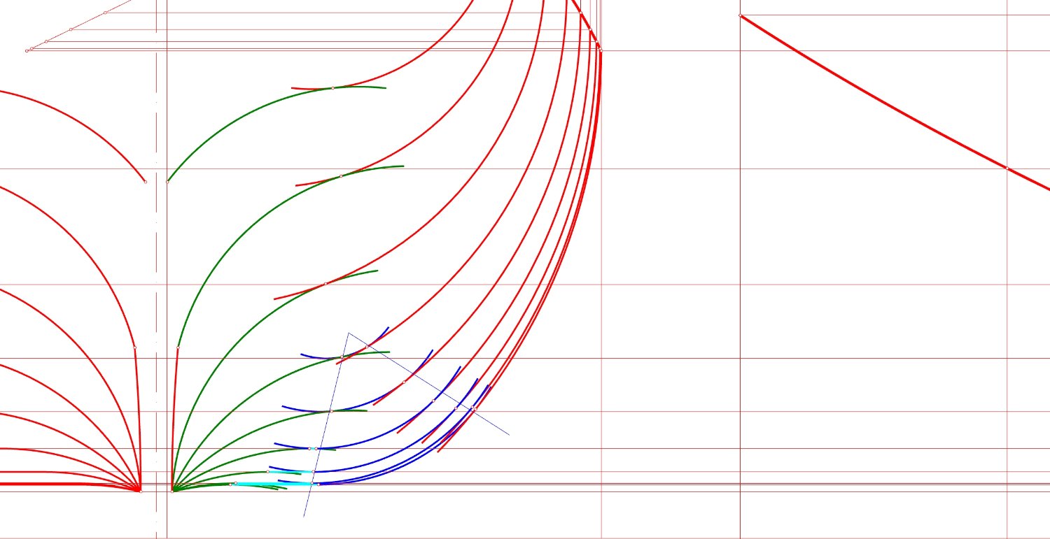
Firstly, I determined through fitting that all green arcs have the same radius, and all blue arcs have different radii. Then I determined more or less arbitrarily the triangle for the blue curves. The red lines were drawn first, then (inside the triangle) the blue arcs as tangents to the red arcs and the horizontal lines, and finally the green arcs tangent to the previously drawn sections of the profiles. It would even be similar to the conventional moulding method if it weren't for all those variable radii. For greater clarity, I have included another diagram below.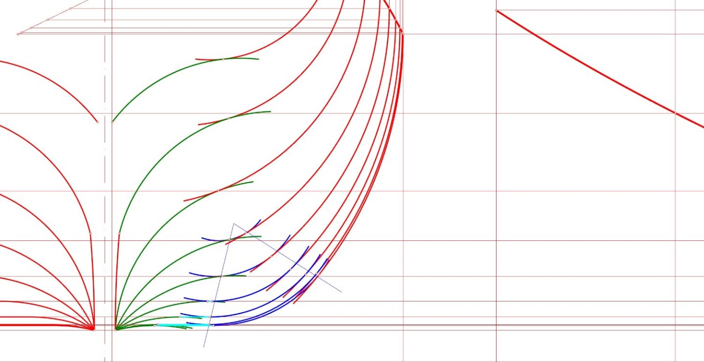
-
William Sutherland's concept of ship hull design, 1711
Waldemar replied to Waldemar's topic in Nautical/Naval History
Done. The way the designer of this ship plotted the bottom curves on the plan is not as elegant as the method described by Sutherland. However, this does not matter much in practice, as in both cases these curves were redone by the shipyard workers during the actual construction of the ship anyway. And most likely in an identical manner.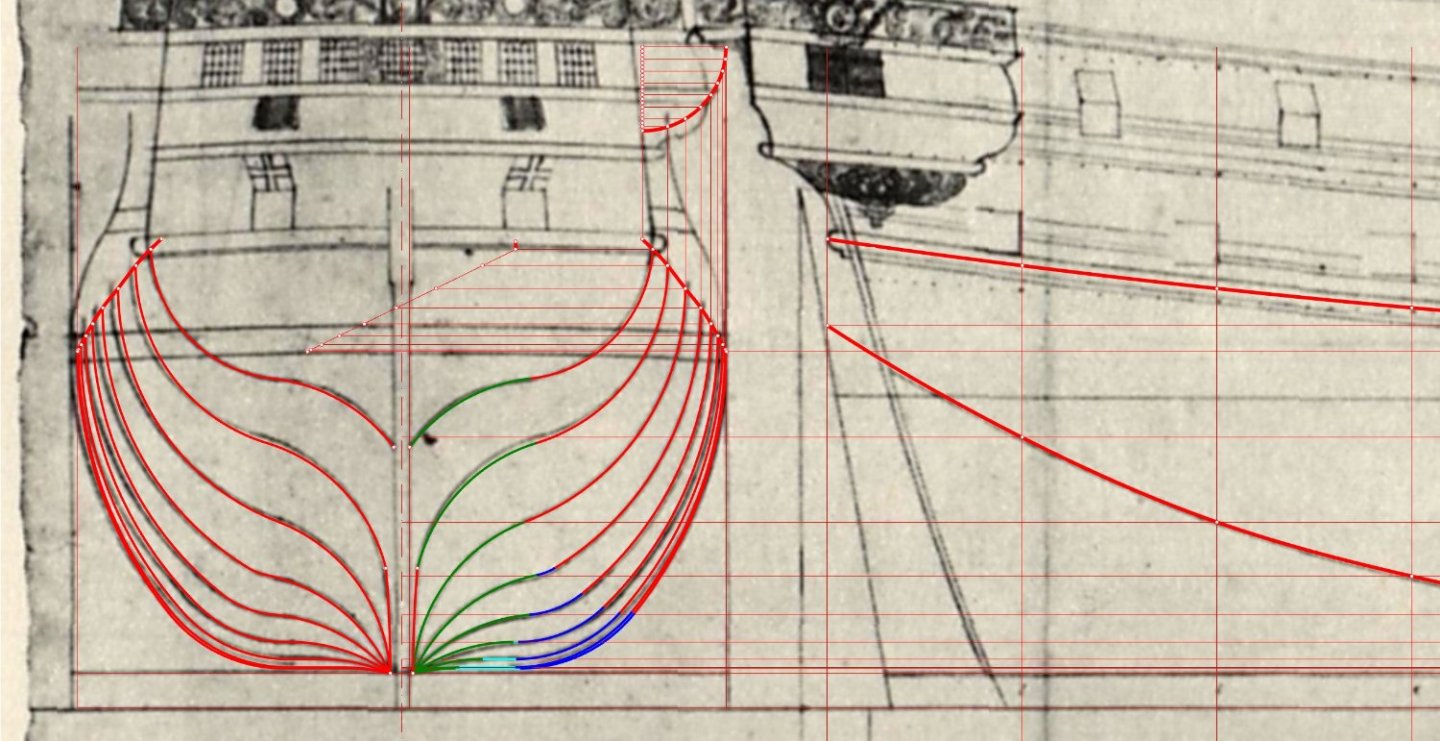
-
William Sutherland's concept of ship hull design, 1711
Waldemar replied to Waldemar's topic in Nautical/Naval History
Trying to reverse engineer this plan in a more regular way (btw, the ship's designer is Claus Reimer). The general method is already understood, only those troublesome floor curves remain to be reconstructed...
-
William Sutherland's concept of ship hull design, 1711
Waldemar replied to Waldemar's topic in Nautical/Naval History
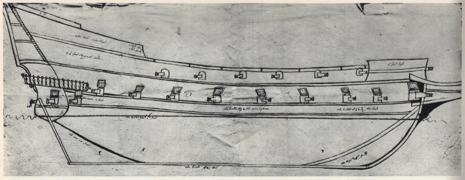
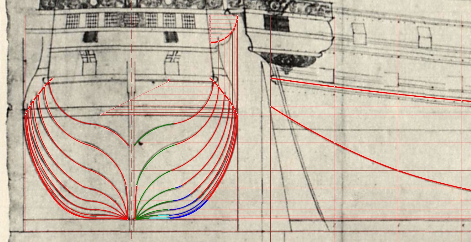
Nihil novi sub sole. 🙂 To conclude this thread, I also present a design draught of the Danish ship Printz Christian built in 1665, i.e. some 45 years before Sutherland's work was published. A quick check of the frame lines proves that this ship was designed on the conoidal solid principle, so that the cross-sections of the submerged part of the hull have the shape of a perfect arc with varying radii for different frames (Danish archives). Moreover, the shape of the floor curves is somewhat 'suspicious', and I think that these bottom curves are also rather for illustrative purposes only on the plan, to be properly formed on the mould loft in the shipyard, as described in the Sutherland's work.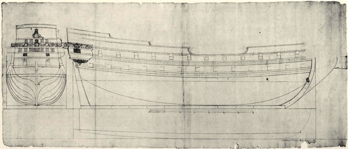
-
William Sutherland's concept of ship hull design, 1711
Waldemar replied to Waldemar's topic in Nautical/Naval History
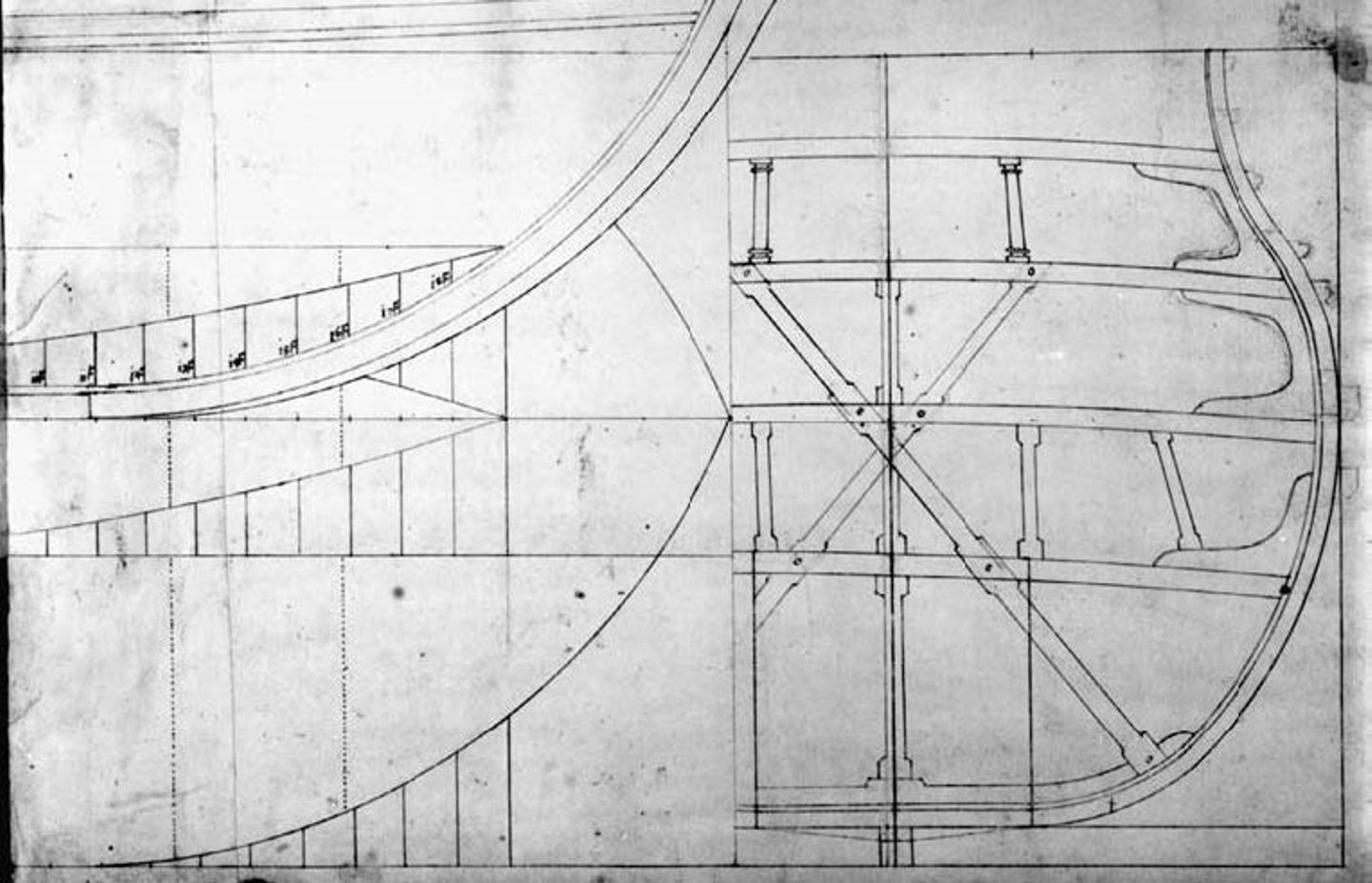
This rather poor copy of the plan, which I estimate to date from the early 17th century, is perhaps the best visual example of these practices. The profiles of the main frame and the forward 'quarter' frame are not even designed as having floor curves. Only the shapes above the rising floor line were drawn, and the floor curves were apparently 'left to the discretion of the actual builder' by the designer of the ship (Russian archives). And there are other contemporary ships' plans which, for example, show these floor curves only as a symbolic faint line drawn rather for illustrative purposes and/or completeness. Just as on this design draught of the Danish ship Tre Kroner (1604) by Scotsman David Balfour (Danish archives).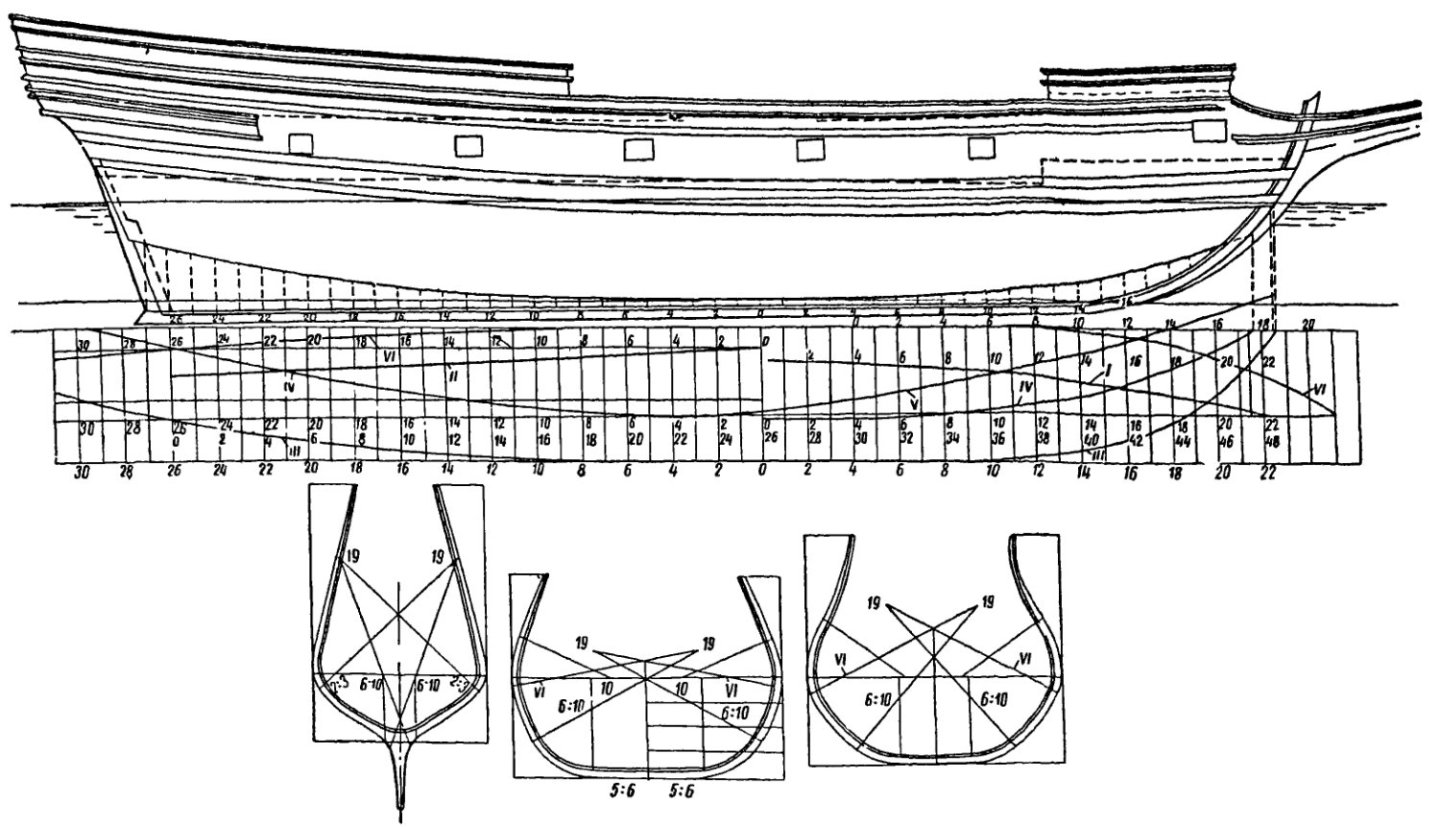
-
William Sutherland's concept of ship hull design, 1711
Waldemar replied to Waldemar's topic in Nautical/Naval History
And, in this state of affairs, it would not be out of place to ask today's modellers: which model would you like to make, according to the design lines or the real ones? 🙂