.jpg.6c90d67e7e9071af590f4d4a2a8bc908.jpg)
Waldemar
-
Posts
986 -
Joined
Content Type
Profiles
Forums
Gallery
Events
Everything posted by Waldemar
-
.thumb.jpg.c6343966b029e7941df5b987d129aac6.jpg)
Jesus Boat ... Rhino
Waldemar replied to tabycz's topic in CAD and 3D Modelling/Drafting Plans with Software
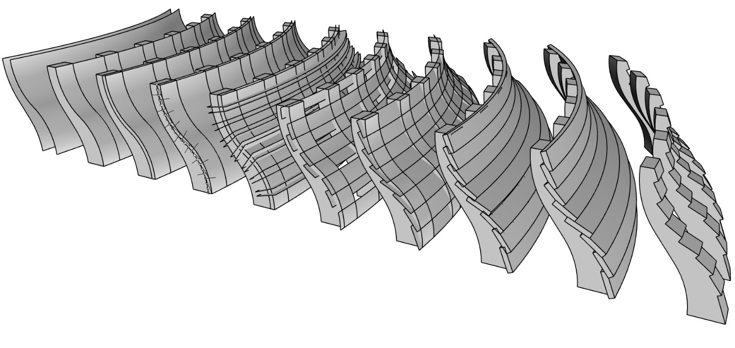
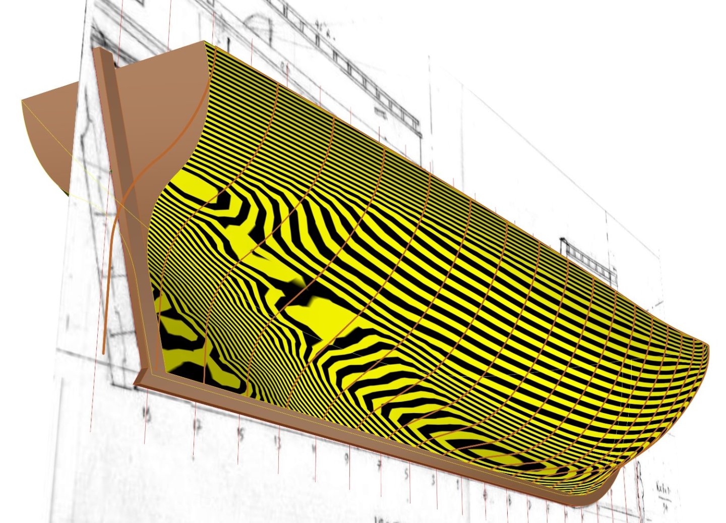
Here's my method for clinker strakes. Actually, I have used its simpler variant, as my surfaces were much flatter and more or less vertical. It means that in step 4 I have made even dividing in vertical direction, and not along the frame profile. Consequently, in step 5 my cutting surfaces were horizontal, and not perpendicular to the surfaces to be cut. step 1: two frame surfaces, inner and outer step 2: frames created, outer surface left for the next steps step 3: outer surface offset by roughly the plank thickness step 4: dividing plan for both surfaces (must follow the run of the strakes set beforehand) step 5: creating cutting surfaces step 6: both surfaces split step 7: lofting the inner surfaces of the strakes step 8: inner surfaces of the strakes offset as solids step 9: (Boolean) cutting edges of the strakes (optionally) step 10: (Boolean) cutting of the frames
-
Jesus Boat ... Rhino
Waldemar replied to tabycz's topic in CAD and 3D Modelling/Drafting Plans with Software
I think I know what is involved. It's the same with my model. It's just not possible to get the course of the strakes in such a way that they have a perfect course in every projection. But the same effect must have been in real ships. -
Jesus Boat ... Rhino
Waldemar replied to tabycz's topic in CAD and 3D Modelling/Drafting Plans with Software
Kevin, I am about to describe my method of shaping clinker planks, but need some time to prepare the accompanying graphics. -
Jesus Boat ... Rhino
Waldemar replied to tabycz's topic in CAD and 3D Modelling/Drafting Plans with Software
Pipes could in theory be the ideal tool, but in practice they generally do not work well. Those with a fixed radius can only produce rectangular boards, i.e. having parallel edges (not very useful as you know). And those with variable radii are usually generated by software with a less than acceptable shape that is very difficult or impossible to correct. Not a bad disaster. The most reliable method I've found so far is to divide the station/frame profiles by an equal number to get a run of planks. But not all the way through, as this usually has to be done segment by segment, with each segment covering only a few runs of planks. Alternatively, from one wale to another (externally) or from one deck to the next (internally). Still, quite a lot of manual adjustments are usually needed. -
Jesus Boat ... Rhino
Waldemar replied to tabycz's topic in CAD and 3D Modelling/Drafting Plans with Software
Kevin, your boats look gorgeous both painted and unpainted. When it comes to lofting planks in CAD, I find it the most difficult task to do on a regular/systematic basis. Relatively flat surfaces are easy, but with heavily convex shapes insurmountable complications arise. Some improvisation is then needed. Perhaps Tabycz would have something to say.... -
Jesus Boat ... Rhino
Waldemar replied to tabycz's topic in CAD and 3D Modelling/Drafting Plans with Software
Better yet, please make it quick so I can peep how you'll handle the rigging. 🙂 -
Jesus Boat ... Rhino
Waldemar replied to tabycz's topic in CAD and 3D Modelling/Drafting Plans with Software
A full 3D reconstruction is intended or just the boat's hull? -
Jesus Boat ... Rhino
Waldemar replied to tabycz's topic in CAD and 3D Modelling/Drafting Plans with Software
Very nice. What (historical) sources have you used, if any? -
William Sutherland's concept of ship hull design, 1711
Waldemar replied to Waldemar's topic in Nautical/Naval History
Back to Sutherland and the Restoration yacht. Below is a sketch showing in detail how the frames of the double conoid hulls were drawn. and all the necessary elements are there. It is difficult to imagine something simpler and efficient at the same time in terms of design method. The stern is constructed in the same way with the difference that the hollowing radii are variable and equal to the corresponding radii of the lower conoid, with the exception of the very last frames, where hollowing radii are equal to the corresponding upper conoid. That's it.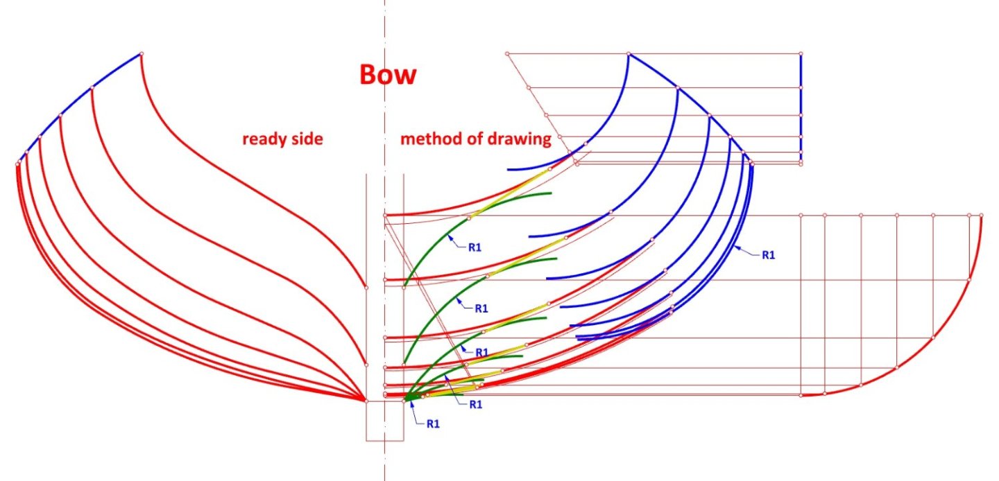
-
William Sutherland's concept of ship hull design, 1711
Waldemar replied to Waldemar's topic in Nautical/Naval History
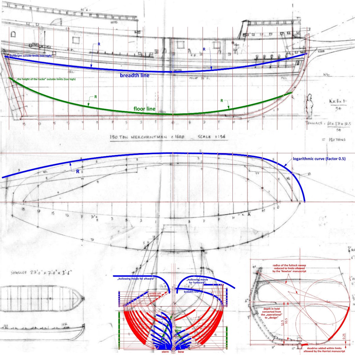
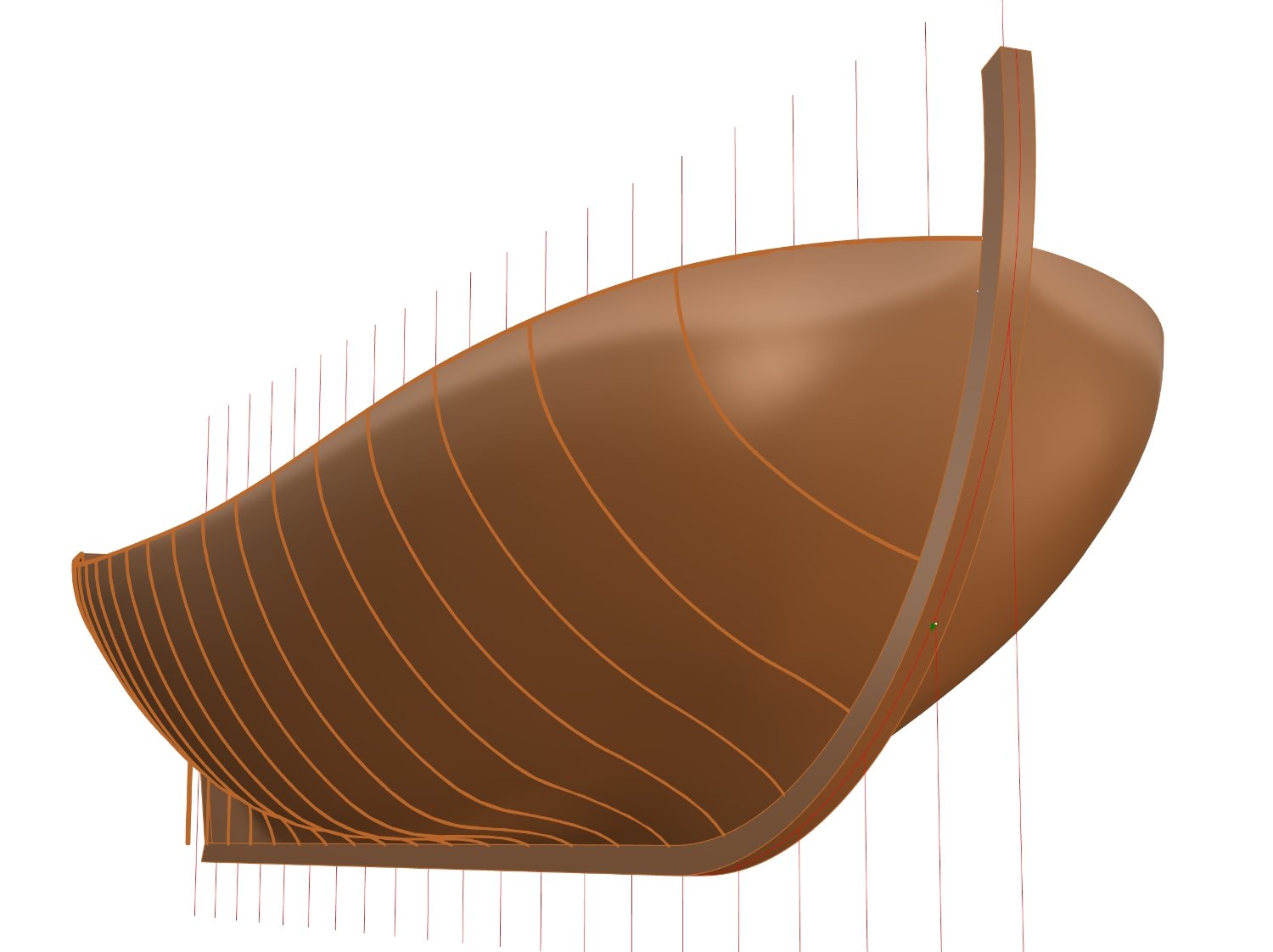
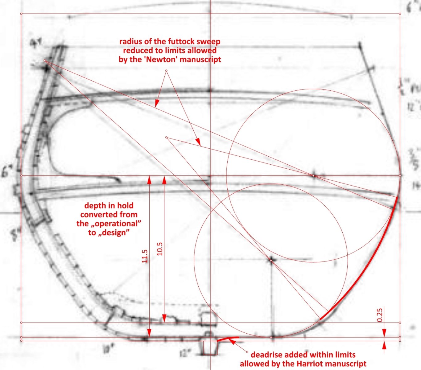
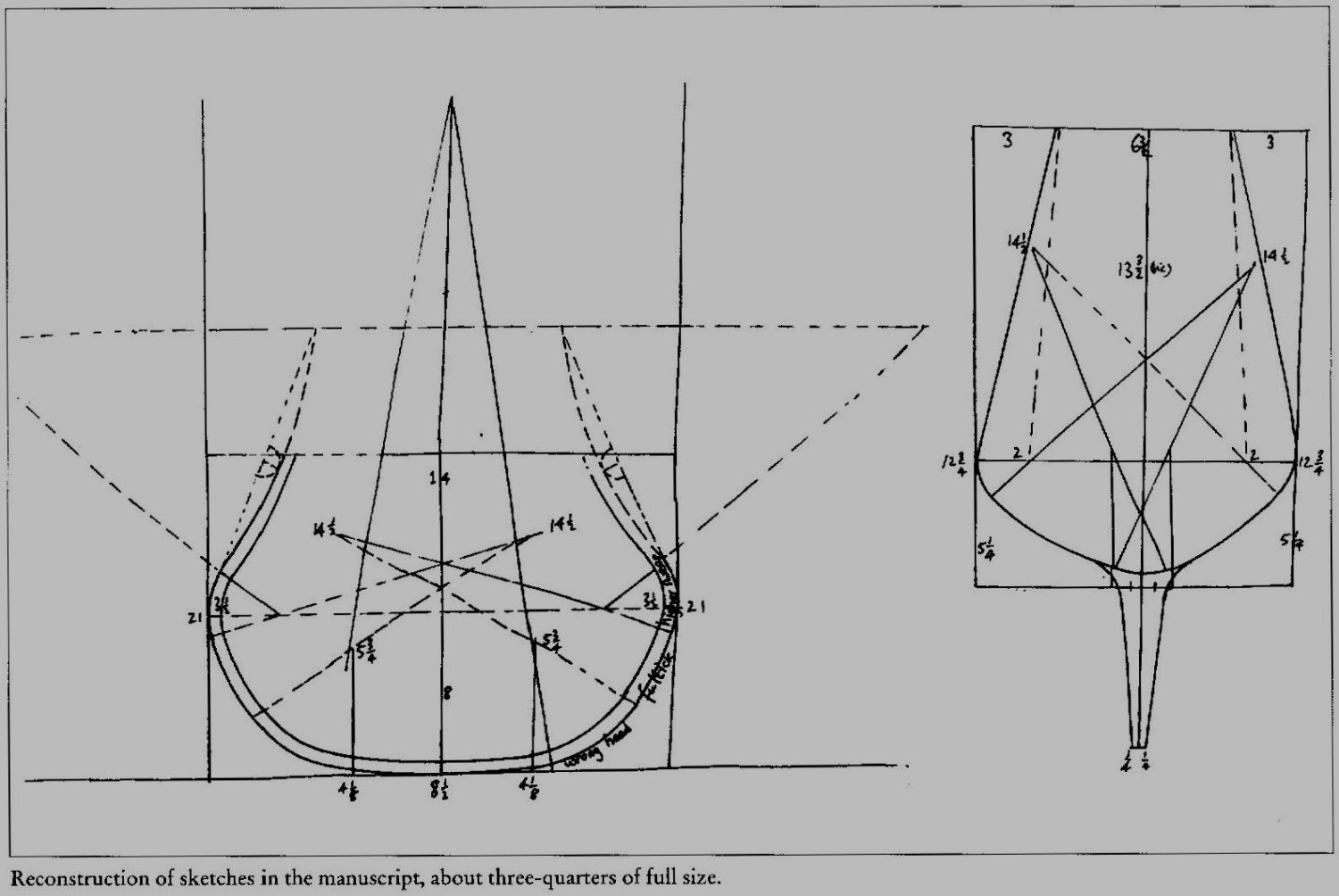
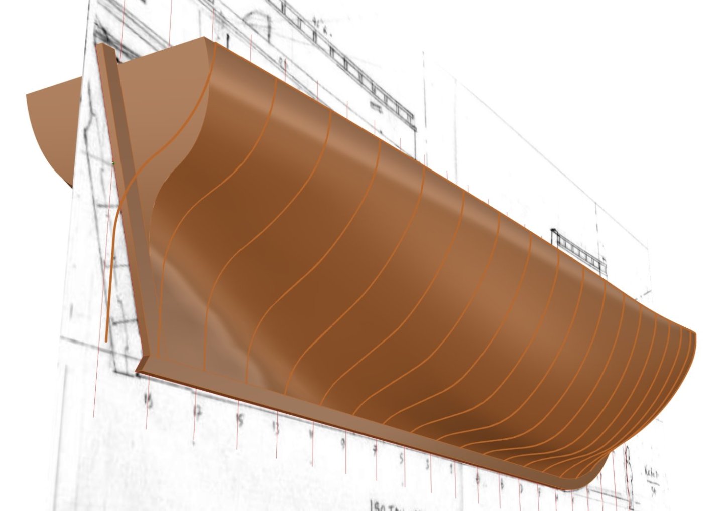
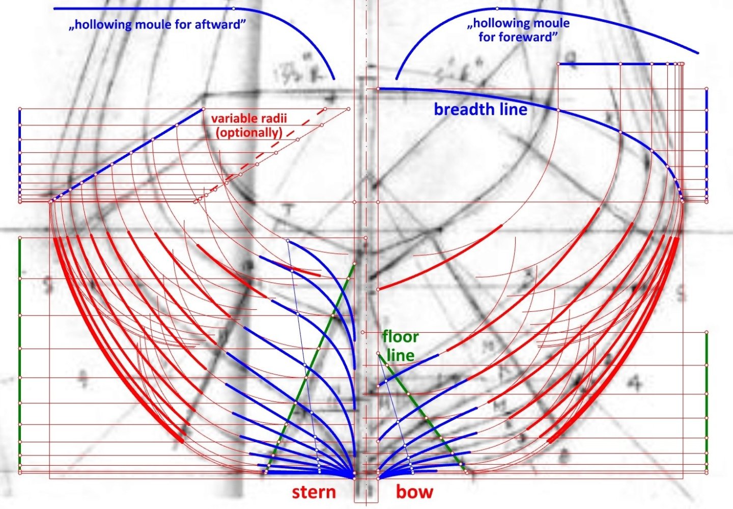
In order to show something concrete again in this thread in as clear a graphical way as possible, and perhaps persuade Mark to design an Elizabethan era ship himself, I present below a relatively easy way to do it. It can be useful for graphical as well as non-graphical and partly graphical methods of ship design. Precisely, it is about achieving the most important and at the same time conceptually most difficult shape of the submerged part of the hull. This is one of the many variants of the moulding method (hauling down/pulling up), giving pre-designed frames along the entire length of the hull. A computer is not necessary as you can draw by hand, but it speeds up the work considerably and improves precision, as can be seen in the accompanying graphics of a comparative nature. This is why the sketch of a merchant ship circa 1600 kindly provided by Druxey will be used as a starting point. For the sake of better comparison, I have retained most of the parameters adopted in the original sketch, apart from a few elements that I have seen fit to modify. One must start by establishing the overall proportions of the hull, the shape of the axial skeleton elements and two guides of the most significant importance – the rising/narrowing lines of the breadth and the floor. This is not difficult, but it is best to make use of works on naval architecture, shipbuilding contracts and shipwrecks. However, as I wrote earlier, this is beyond the scope of this thread, as I would also like to do other things in my life besides quoting the contents of other works. Next you need to work out the shape of the main frame. Basically, I used the original design, but added a deadrise so that when the limber holes are cut out, the bottoms are not weakened, and bilge water can flow more easily to the keel and pumps. I have also reduced the radius of the all-important futtock sweep to get larger capacity and to the limits indicated in the 'Newton' manuscript. If anyone has read this thread from the beginning and has even a basic understanding of geometry, the attached sketch is self-explanatory. It must be stressed, however, that it is not necessary, or indeed allowed, to use waterlines and diagonals to correct the hull lines, as this will only deform the shape obtained by the historically correct means. There is no mention of the use of these design tools in early English works on shipbuilding (Baker, Newton, Harriot, anon. 1620, Bushnell), and they only begin to appear on plans in the second half of the 17th century. Properly applied moulding method together with a properly selected main frame shape almost guarantees correct, smooth hull surfaces. Obtained shapes may be not absolutely perfect, but this is an inevitable, inherent limitation of this method. Hollowing templates lines ('moules') were added in a systematic way along the entire length of the hull. Their shape is described in the 'Newton' manuscript (see my post #57), and the method of application in my post #7. I guarantee that a professorial degree or even an engineering degree is not needed for this. It is also safe to say that most would not be able to cope, at least not immediately. I invite you to experiment for yourself. Enjoy!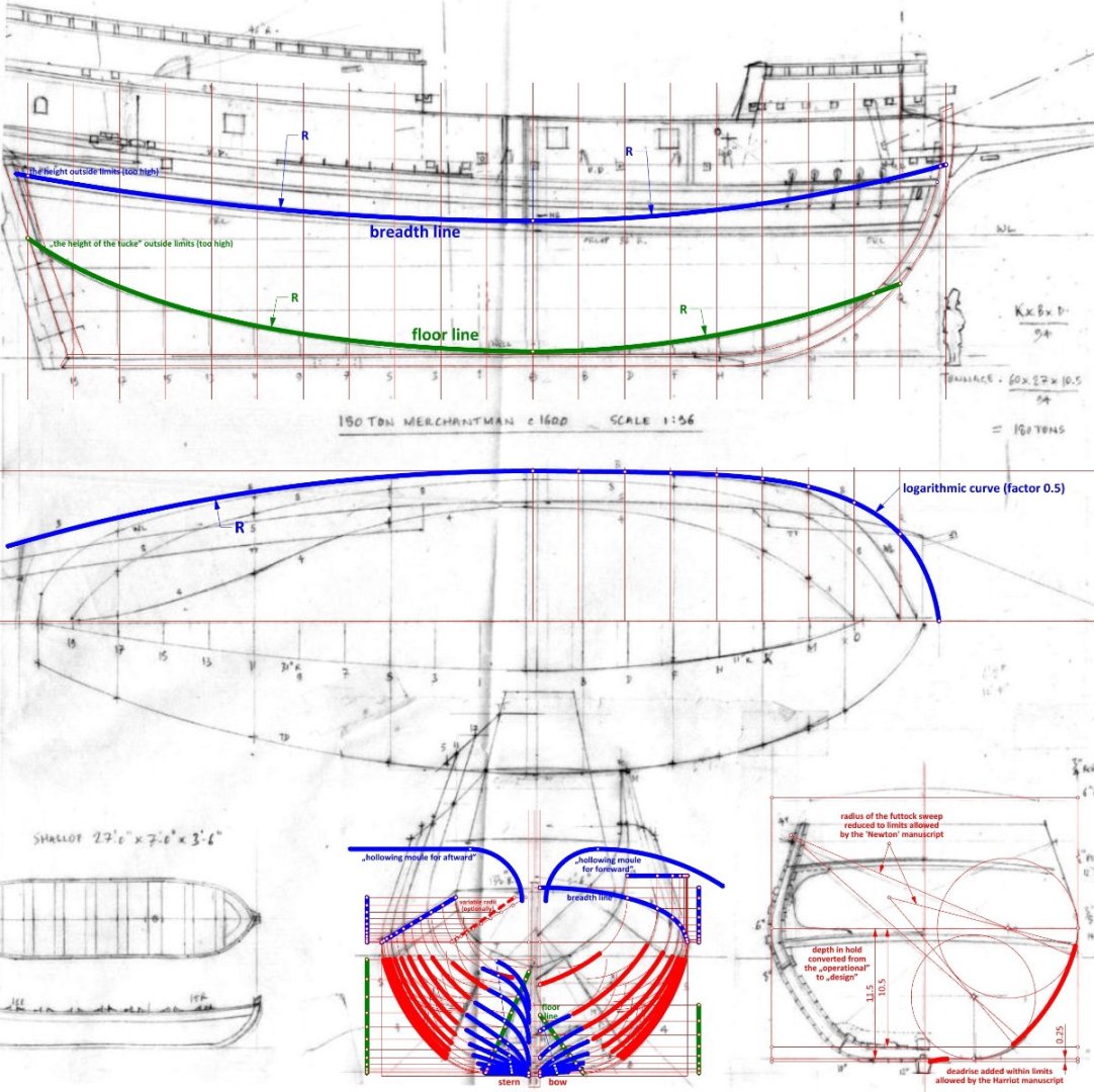


-
William Sutherland's concept of ship hull design, 1711
Waldemar replied to Waldemar's topic in Nautical/Naval History
We are thinking along similar lines, Jud. Unfortunately, my time is limited, and I now prefer to focus on lesser known or obscure aspects of period ship design. If a broader context is needed, there are a great many works on naval architecture available. -
William Sutherland's concept of ship hull design, 1711
Waldemar replied to Waldemar's topic in Nautical/Naval History
Yes Jud, you are absolutely right. This thread is not so much about why hulls were shaped one way or another, but rather how this was achieved. However, this equally interesting subject can also be successfully pursued in most early works on shipbuilding or naval architecture. And it probably goes without saying that the two issues are indeed very closely linked. -
William Sutherland's concept of ship hull design, 1711
Waldemar replied to Waldemar's topic in Nautical/Naval History
🙂 Mark, may I ask the reason for your "Confused" reaction? You don't like that the cono-cuneus curves don't fit the original model anything to write about them, you don't like that I wrote about it, or something else? -
William Sutherland's concept of ship hull design, 1711
Waldemar replied to Waldemar's topic in Nautical/Naval History
There is "only" one small problem, these cono-cuneus curves do not match the frame scans. That's it. -
Redoing Oseberg
Waldemar replied to KrisWood's topic in CAD and 3D Modelling/Drafting Plans with Software
Project Project curves/points toward a construction plane to intersect a surface. Pull Pull curves/points in the surface normal direction to intersect a surface. Intersect Create point objects or curves at the intersections of curves and surfaces. From the above, choose the most appropriate way for your actual need. In the last case you will only have to make surfaces from your beautiful curves beforehand, too easy to explain this. -
Redoing Oseberg
Waldemar replied to KrisWood's topic in CAD and 3D Modelling/Drafting Plans with Software
Kris, you are becoming more and more CAD professional. 🙂 I'll give you ways to project lines onto surfaces in a moment. In the simple, soldierly words: forget it, it is all waste of time... -
William Sutherland's concept of ship hull design, 1711
Waldemar replied to Waldemar's topic in Nautical/Naval History
For those who like theory, the following sketch may be of interest. It explains the principle of the geometrical formation of conoidal hulls in a more elaborate form, consisting of as many as two, actually three, conoids. Naturally, the surfaces of the two upper conoids are tangent to the surface of the lower conoid along two longitudinal lines, as can be seen in the drawing. This was precisely the method used in the design of the Restoration yacht under examination.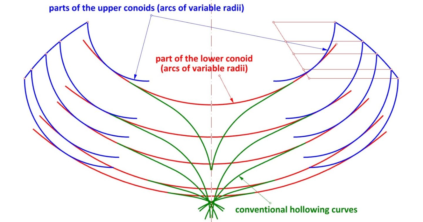
-
William Sutherland's concept of ship hull design, 1711
Waldemar replied to Waldemar's topic in Nautical/Naval History
Hopefully, for some. For me, certainly conclusive. By the way. A monograph on the Restoration yachts by Brian Lavery, Royal Yachts Under Sail, will soon be published. It may even be available in digital format now. Lavery is a trustworthy author, and this monograph is sure to become a standard work on the subject. However, I do not expect him to include an overly detailed analysis of yacht design and construction in this publication, which is after all intended for a wide audience. -
William Sutherland's concept of ship hull design, 1711
Waldemar replied to Waldemar's topic in Nautical/Naval History
Well, this further explains nothing. Never mind, I'd better leave such explanations alone now, because I think I have something more interesting. Originally, I did not intend to verify this, but in the end, I too carried out my own reconstruction of the frame shapes of this contemporary model (Restoration yacht). This was in order to form my own view of those cono-cuneus curves. For this, I used first the conventional method of shaping frames known from the Sutherland's work, in the 'as designed' variant (as opposed to the shipyard version using templates). Either way, both of these variants used only simple geometric figures - arcs and line segments for this. In short: if the published 3D scans of the model are to be trusted, it appears that the use of the conventional method as described in the Sutherland's work gives exceptionally good results (i.e. the reconstructed lines are very well aligned with the model frames). Then I compared the reconstruction lines as printed in the publication, based on the cono-cuneus curves with the same 3D scans and the results turned out to be inferior. In this light, while I might have had some doubts before, now the proposal of cono-cuneus curves to reconstruct frame shapes has lost credibility for me. I have called the following composition 'A Perfect Fit' (lines are mine and the 3D scans of the frames profiles were taken from the study A Restoration Yacht's Design Secrets Unveiled: An examination of a ship model with reference to the works of William Sutherland, The Mariner's Mirror 2021, Volume 107, Issue 2). Not all the lines are shown in the drawing, especially the auxiliary ones. However, the most important thing is that it is perfectly possible to geometrically recontour the shape of the model's frames just from the arcs and line segments.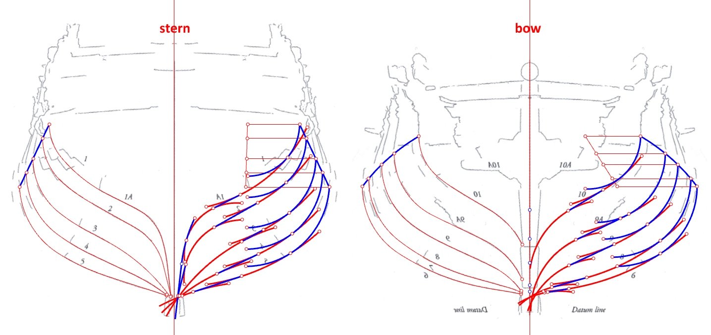
-
William Sutherland's concept of ship hull design, 1711
Waldemar replied to Waldemar's topic in Nautical/Naval History
I am glad that you accept my observation about conoidal hulls as early as 1600. Can you point to any period work on shipbuilding describing or even suggesting the use of "the cono-cuneus curves to develop the lower hull below the conoid"? Druxey, you may have reconstructed the general shape of the merchantman's hull based on the 'Newton' manuscript, and I have no intention of verifying this. But we are now talking specifically about bottom curves, and I don't even see a resemblance to their shapes as described in the manuscript. Your statement: "Changes in radii were later adjusted to occur at the joint lines" is quite incomprehensible. Either way, according to the manuscript, there should be no 'changes in radii' at all. -
William Sutherland's concept of ship hull design, 1711
Waldemar replied to Waldemar's topic in Nautical/Naval History
Druxey, thank you, but to tell you the truth, I continue to see little connection between the information in the 'Newton' manuscript and the drawing and description you have provided in relation to the bottom curves. By the way, I also just discovered in the concluding remarks of the 'Newton' manuscript that conoidal hulls (i.e. with variable radii for the different frames) were nothing novel already around 1600. -
William Sutherland's concept of ship hull design, 1711
Waldemar replied to Waldemar's topic in Nautical/Naval History
Wayne, I am glad you are comfortable with the subject matter. Information on David Balfour and his ships can also be found in the following works, among others: Niels M. Probst, Christian 4.s flåde (1996), Christian P.P. Lemée, The Renaissance Shipwrecks from Christianshavn (2006), Martin Bellamy, Christian IV and his Navy. A Political and Administrative History of the Danish Navy 1596–1648 (2006), Henrik Christiansen, Orlogsflådens skibe gennem 500 år. Den dansk-norske flåde 1510-1814 og den danske flåde 1814–2010 (2010). The works you have listed are both very important and interesting, but as I have already written, none of them defines the shape of the bottom curves in a clear way, if at all (and Battine's inventory-like compilation does not deal with the issue of hull shape design at all). This is precisely why Sutherland's work is so informative in this regard. Thank you again for your interest in this thread. -
William Sutherland's concept of ship hull design, 1711
Waldemar replied to Waldemar's topic in Nautical/Naval History
Yes, here is my comment: two photographs of the model from around 2020 (and still with perspective distortions) are not proof of anything. Rather, I would expect a graphical or at least textual demonstration of the method, as I have done before, also at your request. And an indication of the relevant passage in the 'Newton' manuscript would not be out of place, so that comparison could be made. -
William Sutherland's concept of ship hull design, 1711
Waldemar replied to Waldemar's topic in Nautical/Naval History
It is also worth noting that the author of the manuscript does not talk at all about how to draw these curves on paper, but immediately describes how to prepare templates/moulds for use in the shipyard. Anyway, the whole description seems to be about the non-graphic method of shipbuilding. -
William Sutherland's concept of ship hull design, 1711
Waldemar replied to Waldemar's topic in Nautical/Naval History
The below description concerning the hollowing/bottom curves was taken from an anonymous (so-called ‘Newton’) manuscript of the English origin of ca. 1600, as published by Richard Barker in The Mariner’s Mirror 1994, Vol. 80, No 1, pp. 16–29. Except Sutherland’s work, this is perhaps the best (or maybe better: the most detailed) source from this period and from the northern part of the continent on this usually neglected issue. Unfortunately, the pertinent description is not complete either – while the shapes of the hollowing moulds were explained for both the forward and after part of the hull, the author apparently forgot to describe their use. ‘20. The length of the sweep of the hollowing moule for aftward must take his proportion from ye length of the sweep of the wrong head & must not be more then 5/6 nor less then 1/3. This arch hath a straight line joyned to it with a true touch wch serveth for the lower part of the moule, & the arch for the higher part. And so the whole moule consisteth of these two parts. The back of the moule & the higher part doth make a true square[;] the making & use whereof shall follow after. 21. The hollowing moule for forward must have no right line in it. Therefore there must be a greater arch to this lesser arch of the after hollowing moule, & the length of this greater sweep must take his proportion from the length of the futtick sweep & must not be longer then 3/4 nor less then 1/4 thereof. The use of this hollowing moule shall follow after’. Neither the author of the manuscript bothered to draw the hollowing curves for the main frame on the accompanying sketch, as can be seen in Barker's redrawing of the original.