


RogerF
-
Posts
102 -
Joined
-
Last visited
Content Type
Profiles
Forums
Gallery
Events
Posts posted by RogerF
-
-
-
31 minutes ago, ccoyle said:
Based on my experience, whatever you do, DON'T use an open flame. Styrene's melting point is pretty low. I'd start with the hot water and try that.
Thanks for that Chris. Yep, if I remember rightly styrene has a habit of bursting into flame when it gets too close to a naked flame! I'm just afraid of breakage if the plastic is not warm enough - need to be soooo careful.
-
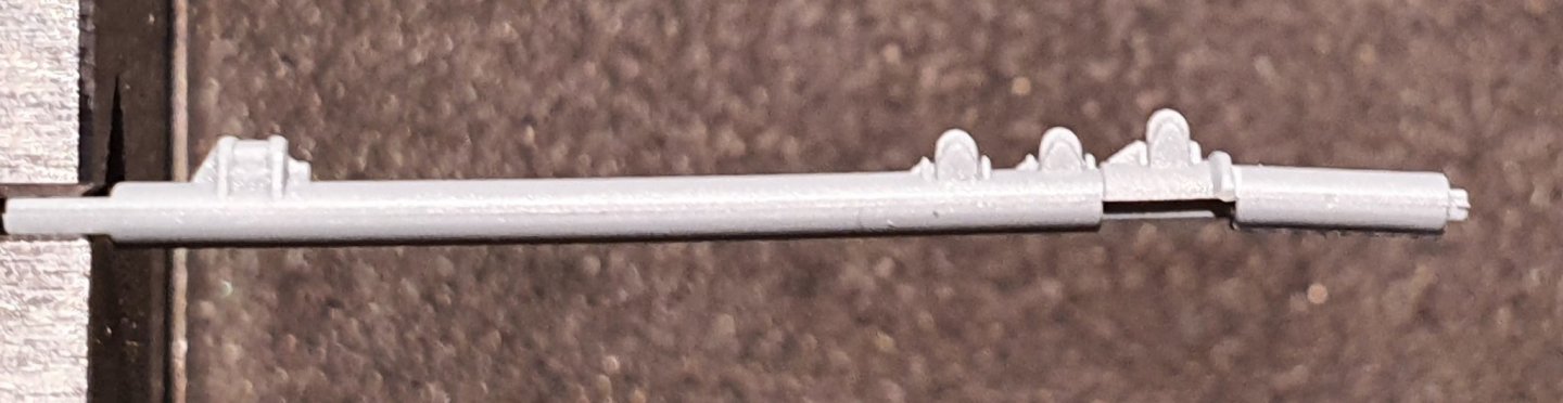
I have a problem with the top end of the lower half of the main mast.
As can be seen in the photo the top end is bent and I'm pretty sure it came out of the box like that - not that it matters!
Any tips/advice how I go about straightening it? The bend is at a weak point and carefully trying to bend it back straight by hand tells me it will break before it's straight again. Clearly some heat is needed here. So how would you guys go about the task?!
Drop it into hot or even boiling water to warm it then try to bend the end?
Warm the end over a candle or lighter?
Wait until we need to turn on the heating (shouldn't be that long now) and warm it on a radiator?
At what temperature does this kind of plastic - soften? Melt?!!
Am scratching my head and would appreciate any advice, especially if somebody has successfully straightened a plastic part like this.
Thanks in advance.
Roger
-
WARNING FOR ALL THOSE OUT THERE WHO HAVE FLYHAWK'S HMS HOOD WITH PE UPGRADE
In the Flyhawk HMS Hood kit there are a couple of mistakes in PE sheet "A".
I only discovered this morning that 4 of the supports for the starfish platform I worked on yesterday are wrongly dimensioned and that Flyhawk have added an update sheet for the relevant parts (which was included in the kit). It is too late for me to do anything about this now, which while meaning that the construction is inaccurate it also means that the two legs extending forward from the platform are unprotected. I wondered about this as I was building with the 'wrong' parts but just assumed it must be right. Very annoying considering there is no mention in the instructions that updated parts are included.
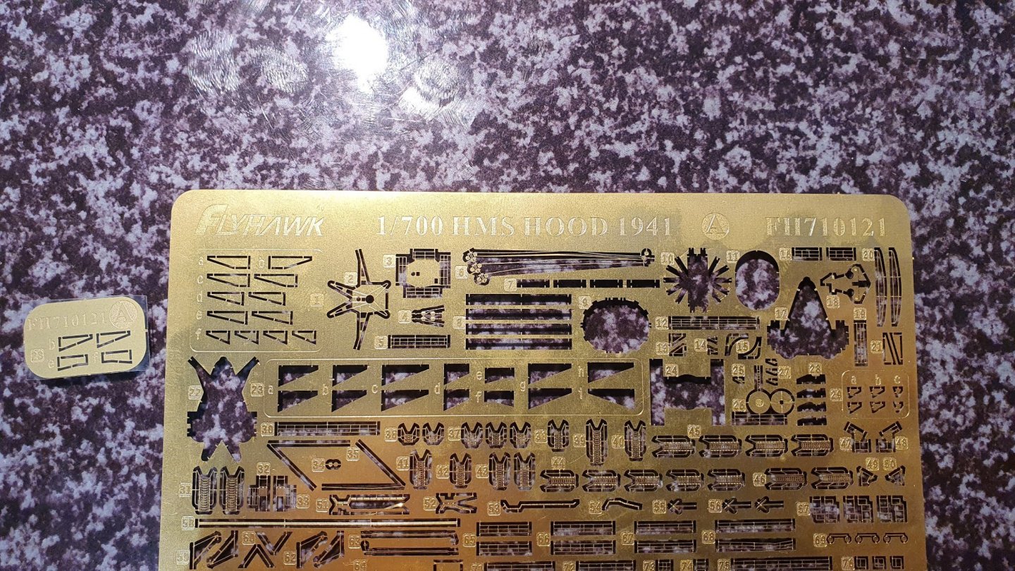
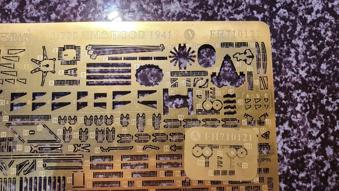
The second update is to two AA guns mounted on platforms. On PE sheet "A", there is only one platform (part 26) but as can be seen in the 2nd pic there are now two - 26a & 26b - as there should be and that they are handed, left and right. Included on the update sheet are the necessary platform supports for the '2nd' platform. Interestingly these handed platforms are included in the illustrated instructions - as though they were on the main sheet. The illustration for the starfish platform however, is wrong in the relevant areas.
I have no idea (yet) where Parts "76" included on this update sheet are destined but there's little doubt I'll remember where they are when the time comes after my experience with the starfish platform!
Hope this prevents others making the mistake I made.
Roger
-
Lots of dry-fitting to establish the sequencing of build prior to first airbrushing - hull and some superstructure parts. I want to avoid endless spray jobs by grouping assemblies and groups of parts together wherever possible.
![20211003_191200[1].jpg](https://modelshipworld.com/uploads/monthly_2021_10/36054223_20211003_1912001.thumb.jpg.7e6440956b08339620887e98b5d5ee03.jpg)
- king derelict, yvesvidal, mtaylor and 3 others
-
 6
6
-
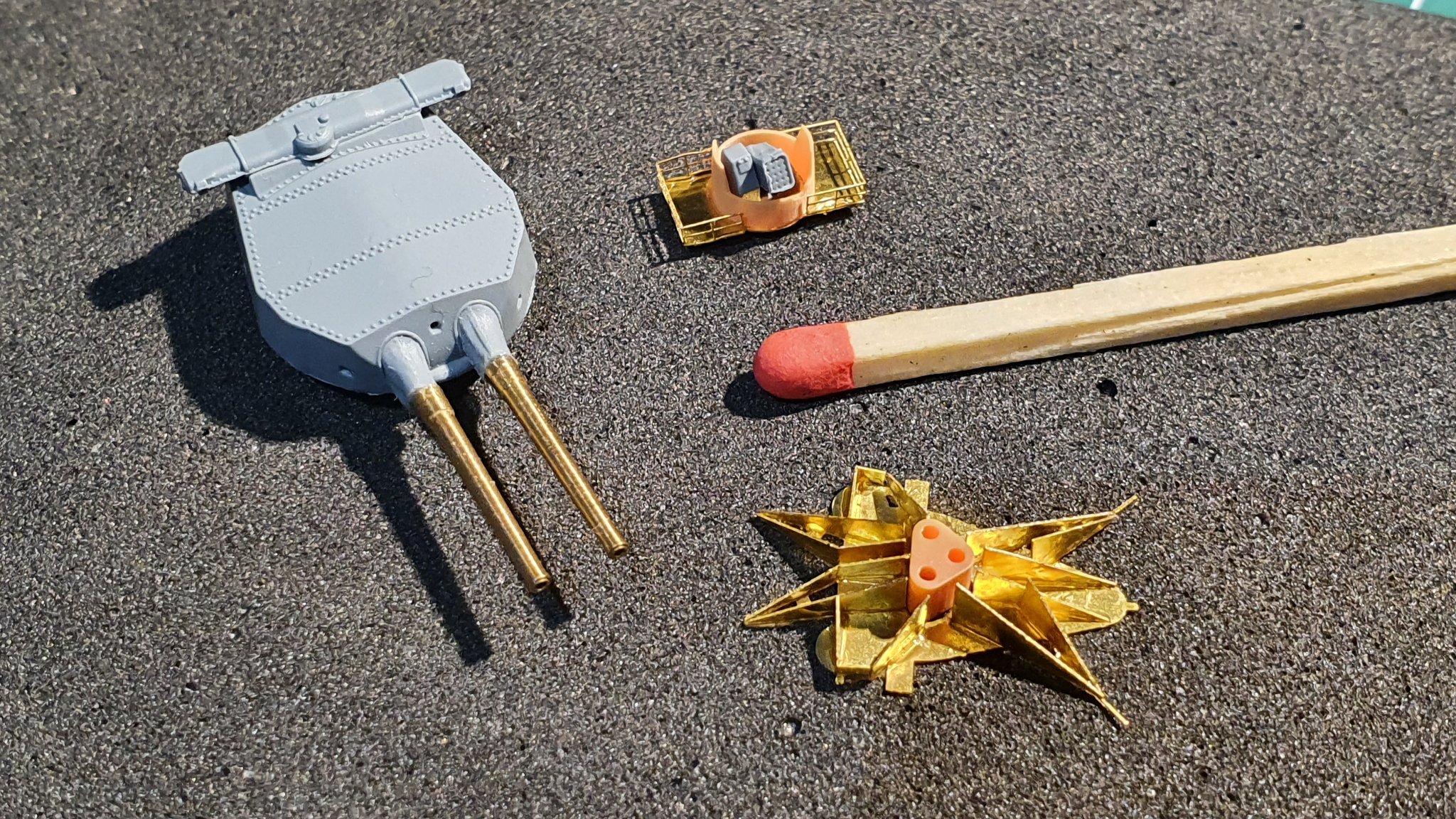
In posting #14 above, I bemoan the fragility of these 1/700 PE parts using the starfish-platform base as an example. Yesterday and today I set out to tackle PE work afresh. I discovered that when separating a PE piece from the sheet that there is a 'sweet-spot' on the bit between the part and the sheet it's attached to which can be severed with relatively little pressure giving that welcoming 'click' mentioned by others that signals breakthrough. I had assumed the knife should be as close to the part as possible but that is not the case. Secondly I devised methods of holding even miniscule parts so that the burrs can be removed with a small file. This can be advisable where small support struts are glued edgeways on to a flat piece of PE as in the example below. I took the starfish platform base from posting #14 and added the support beams. I also tackled the rocket-launcher platform that will sit atop the rangefinder of B-turret.
Neither assembly is perfect by any means but represent a big step forward for me in working with PE. One final lesson I learned (the hard way) is simply only handle PE parts and assemblies when you absolutely have to. Unnecessary handling is just asking for trouble.
So, here are the results of my latest efforts with a match-head as size comparison. By persevering over the last two days, I now feel more up-beat about the whole project.

- king derelict, yvesvidal, Canute and 6 others
-
9
-
Two-dimensional or not, when painted and in place they're going to look the business but wow, what a lot of work is involved and you have certainly mastered the intricacies of PE in this scale - I doubt I'll be as proficient when I turn my attention to the AA guns. I think your Hood will look stunning when finished, and well deserved. The two-dimensional 'look' will only be evident when viewed with optical aids, if at all. It always surprises me when I see close-up photos of my work and see how flawed it is but seen as a whole it looks just fine (well to my eyes!). The camera renders the subject quite magnified which is of course unrealistic.
Roger
- popeye the sailor, lmagna, CDW and 3 others
-
6
-
4 minutes ago, CDW said:
There is a certain amount of madness involved in this hobby and while doing these guns it occurs to me this is a good example of it. Maybe not quite as much as the paintings done on grains of rice as I used to see at the Ripley's Believe it or Not museum, but pretty darned close to it. If I were going to do anything smaller, would need a microscope, not an opti visor.
Wonderful.
At the end of the day we put in endless hours of time and effort with insane, microscopic detail because we enjoy it. Set-backs aside, there is tremendous satisfaction to be felt as these things come together. Nobody, but nobody who isn't into scale model building will ever be able to see, let alone, appreciate the intricacies we dish up in a model like this or have any understanding of the challenges it involved, not only for the model builder but also for the designers and manufacturers. But it doesn't matter. If there are imperfections in our model, we know where they are, every last one. Nobody else will see them so it doesn't matter - except to us! As Craig so aptly puts it - "There is a certain amount of madness involved in this hobby..."
-
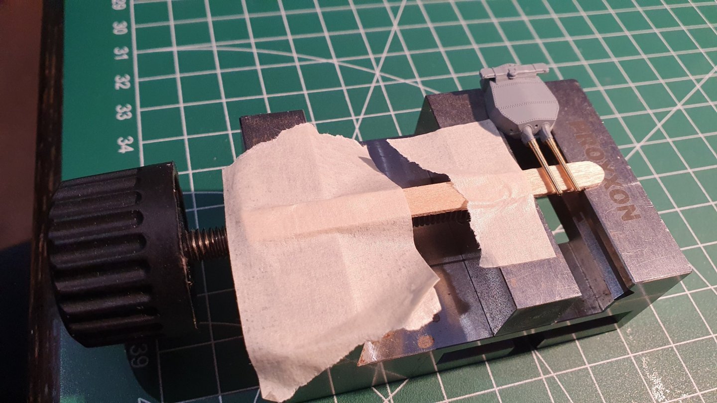
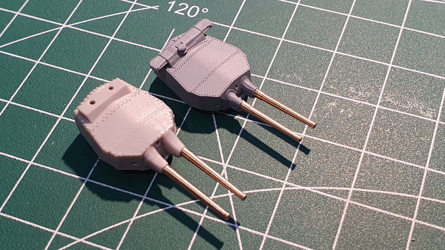
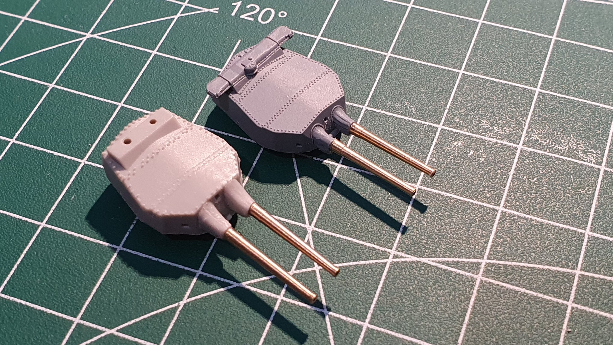
Moving along to the artillery for a change, I first snipped the barrels of one of the ILK Hood's main guns and drilled a 1.1mm hole in the end of each blast-bag. This was tricky because I was holding the stump between finger and thumb. But it worked. I used ILK's parts as practice before daring to approach those of FL's. Flyhawk's barrels and blast bags are a good bit smaller than ILK's but the pin on the brass barrel is only 0,6mm in diameter. The plastic stumps are just too small to hold with fingers, so I glued them into the gun housing, carefully filed the ends parallel and drilled 0,5mm holes in each. I drilled smaller than was needed so I could use the drill to open up the hole and centre it. I still managed to get the starboard barrel a bit off-centre which annoyed me greatly. 😠 As can be seen in the 1st pic, I used a mini vice to hold the turret and a wooden coffee stirrer to get both barrels absolutely parallel - worked a treat. I had also clamped the gun housings in the vice while drilling, which made things much easier.
The 2nd pic shows how different in size FL's turret and barrels are compared with FL's - both are (supposedly) 1/700. 🤥
-
4 hours ago, Old Collingwood said:
I have a quiry with the spraying - the metal container ontop of my airbrush does not hold a lot of paint, so when I come to spray say the hull parts, is it ok having to do part till the paint has run out then re-fil and continue to paint - as there will not be enough paint in the metal cup on the airbrush to paint in one go?
Probably a stupid question but I don't know the answer having never airbrushed anything like this before - and rattle cans are different.
OC.
The hull of the U-Boot I built was a good bit bigger than the 1/700 Hood's and although the paint cup atop my airbrush is of a reasonable size I nevertheless needed to re-spray some areas for one reason or another and it was fine. For priming the entire hull, one solution in your situation might be to spray very thin layers which only really give full coverage when 3 or 4 (even 5) layers have been sprayed. Hood's hull above the waterline is not that big an area which with luck you'll be able to cover with one cup-full of paint. For the lower hull, it might be an idea to spray the sides of the lower hull first, gradually working towards the middle of the bottom - that part of the hull will probably not be visible when the model is finished and mounted on a stand. Also if there are any visible 'joins' in the paint they can be smoothed over with fine sandpaper and sprayed over, this is what I needed to do when a layer of gloss varnish went 'wrong' and had to be addressed - I'm assuming here that you'll be using acrylics. I don't even have a tank but even this disadvantage didn't prove a problem. Hope this helps, OC.
Roger
- mtaylor, king derelict, Canute and 2 others
-
5
-
7 hours ago, king derelict said:
Based on the Geisenau build, my first big project. I found a couple of points to watch for in future big ship builds.
1 - Watch out for any complicated PE railings on the superstructure that might be difficult to bend and test fit at a later date. Solutions could be to fit it early before the superstructure gets crowded (that has its own problems), Or pre-bend the railings and set aside for later (in a very safe place). Make a cardboard template early before assembling the deck in question and use that to bend and test fit the railings.
2 - The fit of the wooden decks around the base of the superstructure can be very tight. If you have a fully detailed assembly to fit then you can't afford to get fierce with it to make it sit down on the plastic deck. I had one of the Geisenau structures pop off because it wasn't really sitting on the deck, just wedged in the wooden deck. Its a pain trying to trim the installed deck so anything you can do to confirm its going to allow the structures to drop in place is a good thing.
You probably know all this so apologies for clogging the thread if uneccessary
Alan
This is exactly what I have come to love about this forum Alan. As I start to (slowly) come to grips with my Hood I realise how daunting a task it would have been without the help, advice and golden-tips to be found here online. I will add as much detail of my build as I can in the hope that someone will benefit from my mistakes.
-
9 hours ago, king derelict said:
Thanks for the reminder about the wooden decks. I did get them for the Prince of Wales but I have forgotten them for the Hood. I'll get them ordered tomorrow.
Thanks for the note
Alan
I also ordered the paint masks because when I come to glue the decks in place I want them to stick to the bare plastic deck below rather than be sticking to a couple of layers of paint which might perhaps peel in places allowing the wood to lift.
I'll mask the wood-deck areas and airbrush the detail that will protrude through the wood leaving the deck surfaces plain plastic. It will also keep paint spray off those areas when painting the upper deck areas which are either grey steel or brown (cortecine) linoleum.
- mtaylor, Canute, popeye the sailor and 2 others
-
5
-
8 hours ago, Old Collingwood said:
My start on this will be Way off I feel - as my Dio is taking all my time as its going to be my focal point - even some hostorians interested in it.
So for now - no physical imput here yet.
OC.
Darn.... with both you and Alan not due to start your Hood builds for sometime yet, it looks as though I'm on my own for now. 🙁 Still, I am actually starting to gain confidence with this scale - even with the PE - it'll still be a slow job, but that's ok.
Good luck to you both with your other builds.
-
Great stuff Alan, my Hood came from Hobbyeasy in HK and it took a while but arrived safely and undamaged too. That's a great combination - Hood and POW. Of course you'll have to start the Hood first so I can learn from your progress; Shouldn't be difficult at the rate I work. Did you order wood decks and paint masks too? Authentic Admiralty dark grey 507A for the upper hull and superstructure is available from Lifecolor in the RN WWII, set 1 (Eastern approach "early war") if you're interested. I intend to use Tamiya XF-63 for the grey antifouling below the boot line as it is darker than 507A which should make a good contrast against the black boot line. I'll also use Tamiya XF-64 as indicated in FL's suggested colour scheme for the steel, upper decks.
Now it's just a question of research, reading and re-reading the instructions, deciding on build and painting sequences and which PE parts to use and which to ignore and before you know it, you'll have the model finished while I'm still fiddling with fitting the decks!
-
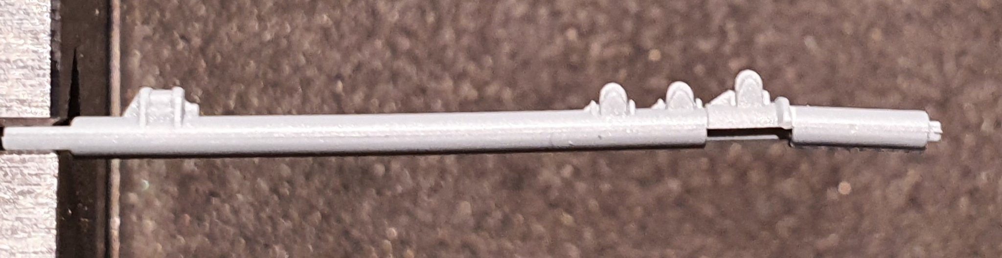
I took a closer look at the funnel-top detail on Craig's ILK Hood and must say it really does add to the look of the finished model, that fine detail really pops out at you. So, I spent nearly 2 hours cutting out the necessary parts and de-burring what I could - I made no attempt to de-burr the spider, no way!!
ILK's Hood has a different system for achieving the spider to FLH's so Craig's experience won't help me here much (apart from telling me to remain calm!).
The spider will either work or it won't, I get it somewhere near or just bin it. But what about the support ring - seen here on the far left. ?
As can be seen on the above FL instructions, the short 'legs' sticking out from the ring are intended to be bent down, more than 90° going by the illustration so my question. How the Dickens do I do that?!! The 'legs' are a mere half a millimetre long so bending without distorting the ring itself will require a unique approach I think - any ideas chaps?!.
Also, nowhere do the PE instructions tell you to remove the spider from the plastic kit version and use the remaining ring as a base for the PE parts although the illustration appears to show a ring that will support the legs of the PE ring.
@CDW Craig, when you bent the walkway railings to fit the walkway, how did you go about it? I'm thinking; glue the straight railing centre part to the walkway and then bend and glue the curves once glue on the straight part has fully cured?

-
5 hours ago, Old Collingwood said:
Are those going top to bottom or around the funnels (I assume they are from top to bottom)?
OC.
The funnel has very finely moulded vertical rivet detail which you can just make out in the second picture. The stays need to be mounted between, and in some cases, around these lines of rivets so must be attached absolutely vertically - a tiny dab of glue on the funnel top and bottom should do the trick but they will look awful if not perfectly aligned. Well I knew this kit would be a challenge. I'm in two minds about the PE funnel tops with walkways and ladders inside the funnel since logically these should be painted black like the inside walls and and grating and will be almost invisible to the naked eye. I might decide to see how I get on with just bending the grating into shape and leave out the interior detail.
The pic shows the instructions for the funnel PE, so judge for yourself.🤥

I've looked back at Craig's I Love Kit Hood build and see that that the kit has a steel PE surround for each funnel with all the rivet, stays and handrail detail etched on. This is a clever solution but of course requires the PE to be bent around the funnel plastic. Their arrangement for the PE funnel top 'spider' and walkway detail is almost identical to Flyhawk's and Craig's results look pretty damn good to me so perhaps I should at least try.
- Old Collingwood, mikegr, lmagna and 5 others
-
8
-
6 hours ago, CDW said:
While they are tiny and tedious, the stays will make a big improvement, and give the model a finished look.
I'm sure you're right Craig and that's why I persevered and cut out all of the first batch, mainly to see if I could remove them all cleanly from the sheet. The problems will probably arise when they are mounted on the funnel together with the (plastic) vertical vent pipes and the complex funnel top-
grating and walkways (if I decide to add those too). I will mount them on their bases before attaching the PE and vents to make handling easier but they will be extremely fragile assemblies to position when gluing in place.
-
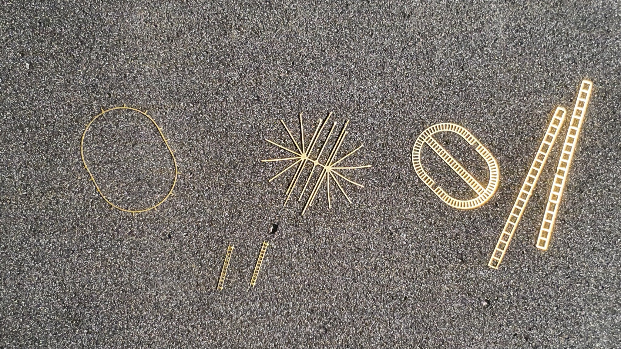
More PE madness!
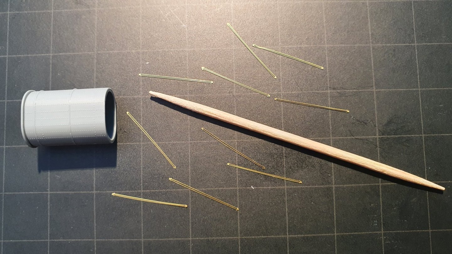
The PE sheet 'A', calls for 8 stays(?) to be fitted to each funnel. Mmmmm! As can be seen each stay has a slot in the middle through which the moulded rivet detail should be visible.....
The PE sheet gives you 10 of these stays - 2 in reserve, which is a good thing because they bend when you just look at them. 😬 I've cut out those for the forward funnel and they can be seen with the funnel and a toothpick for size comparison. I'll cut out the remaining 10 and if I get a total of 16 that are useable then I'll attempt to glue them in place when I get to that stage. Beeswax on the tip of a tooth pick works well for handling these fragile parts but gluing in place should be fun!
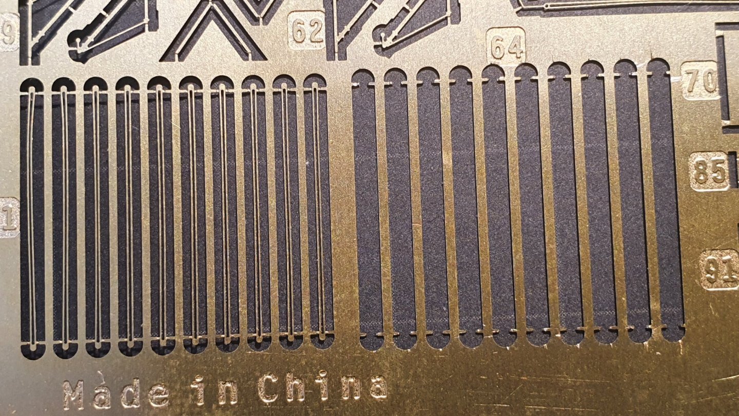
The second pic shows how they look on the sheet - there is no way I'll attempt to file off the burrs though! The two on the far left are bent because I showed them the craft knife blade.
- mtaylor, lmagna, Old Collingwood and 2 others
-
5
-
On 9/21/2021 at 7:16 AM, CDW said:
There is no one good answer to that question. Sometimes it's best to prime and paint first. Other times, it's best to paint in place. However, that primer I showed you is the least prone to crack of anything else I have used. But it's not crack-proof. You're going to find that sometimes painting after it's all bent and assembled is not practical for a number of reasons.
As an example...the outer railings I will paint first before installing on the model. Why? Because I will have already placed the wood deck and the rest of the model will be painted before installing those railings. If I tried to paint them after installing, I would get paint in places where I don't want paint to be.
Indeed. With the Hood, the upper deck is in one piece and has 4 different colours/surfaces. There is the linoleum -deck brown, the steel-deck grey (which I believe is different to 507A), the superstructure grey (Admiralty 507A) and then a section of wood deck, all on the one part. Even with the full masking set I will need to be very careful as to what sequence I adopt for painting and wood deck fitting.
- popeye the sailor, CDW, mtaylor and 2 others
-
5
-
On 9/21/2021 at 4:36 AM, CDW said:
Add some masts, radar arrays, build and detail some boats, then will be ready to do some painting.

In the time you've taken to do all this PE work, I've managed to drill two holes in the hull of my Hood and it's stand!
-
A year on the Bismarck? .... at least a year!
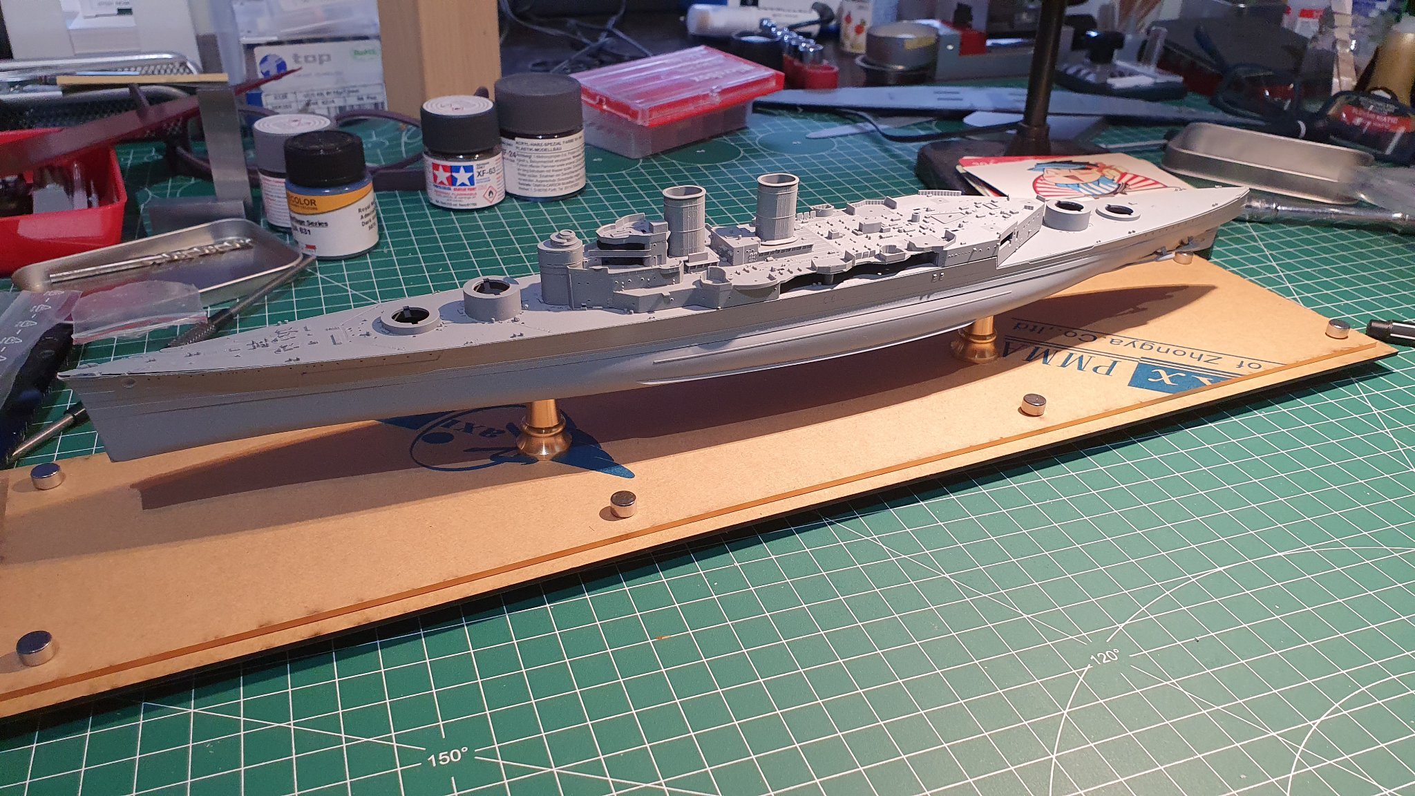
I decided that I wanted to have the model mounted on the Flyhawk stand during the build to have a solid base and to lessen the chances of damage caused by unnecessary touching the delicate detail and PE. Also it will avoid me handling the hull once painted leaving fingerprints on the paint. Consequently I filled the two holes in the hull bottom that Flyhawk put there for the simple plastic stand included with the kit. The proper Flayhawk stand is made from acrylic sheet and I needed to research how that could be done without cracking or splitting the material when drilling. I bought a step drill and a set of countersink bits needed to accommodate the screw heads beneath the stand.
First I measured the positions of the two screws on both the hull bottom and stand and used the step drill to drill two, 4mm holes in the hull and stand then countersunk the stand bottom. I managed to achieve almost perfectly round holes in both hull and stand and went on to remove the protective paper which covered the surfaces of both parts of the stand and mounted the hull using the brass pedestals you can see in the pics.
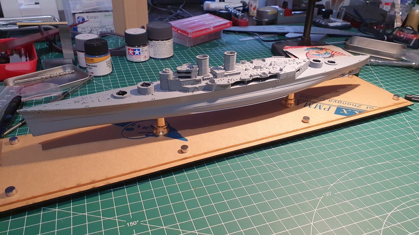
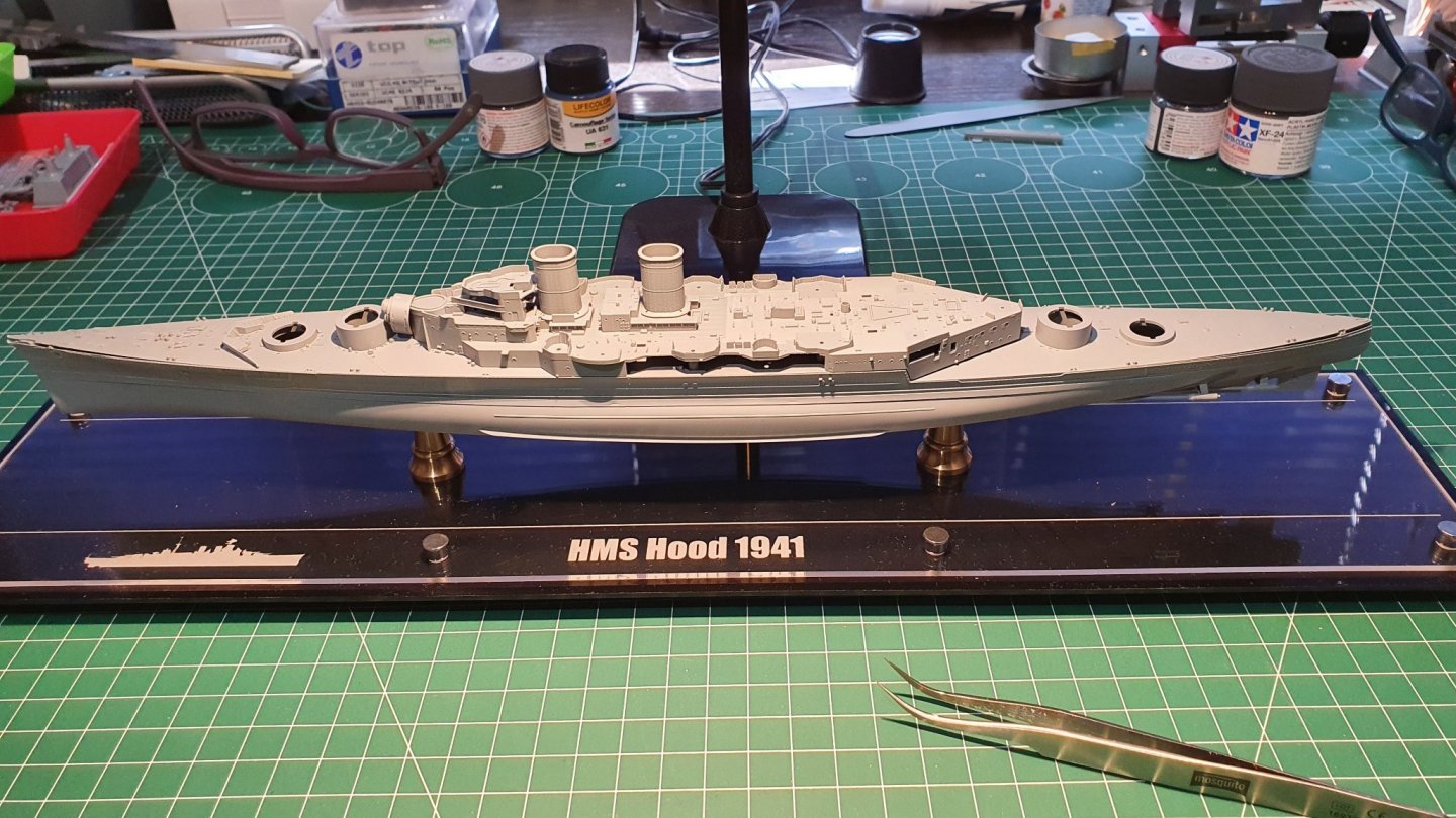
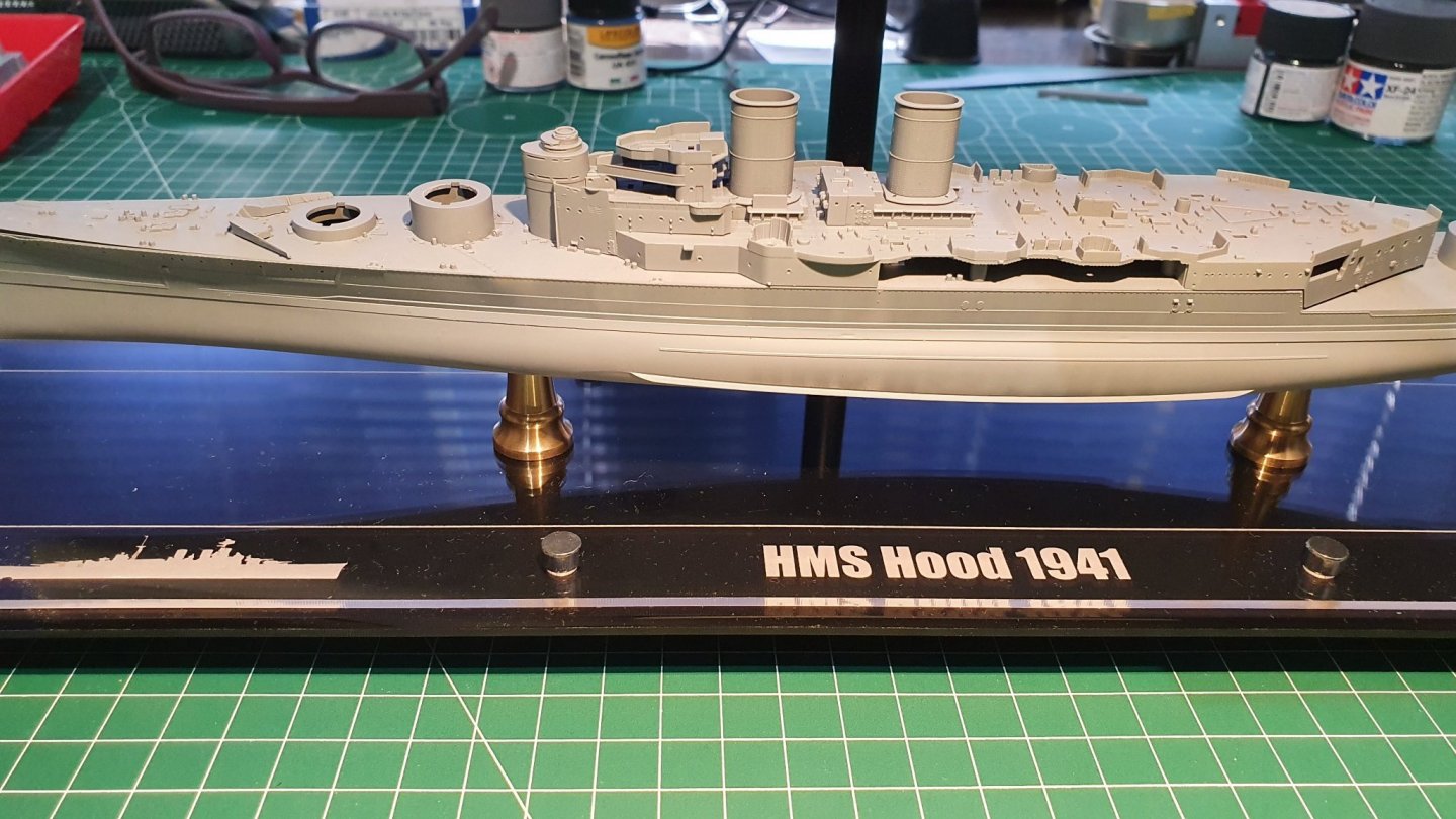
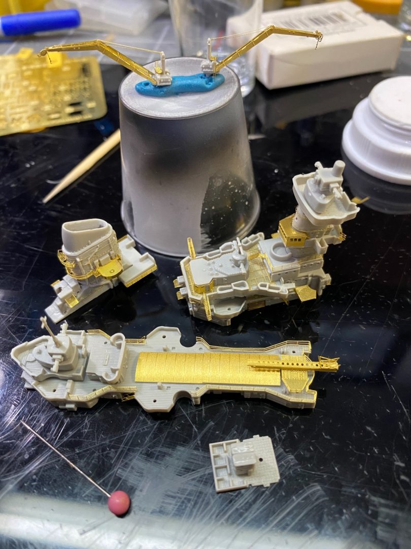
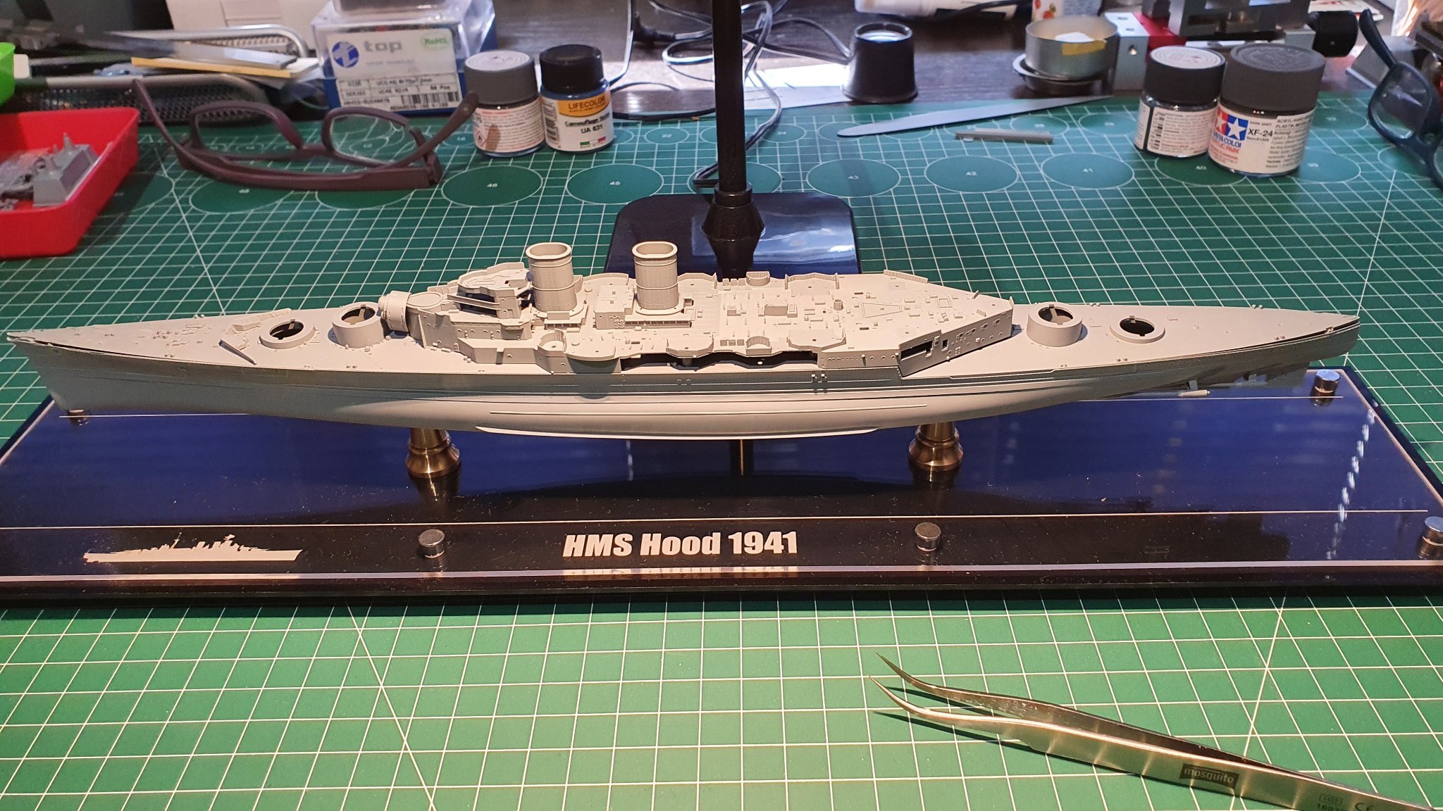
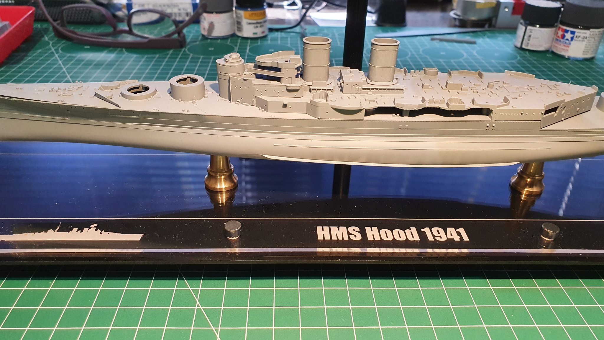
I added a few dry-fitted parts to give an idea of how it will look - one day!
NOW I can get down to priming and painting the hull, first removing it from the pedestals. Once the hull is finished I'll mount it on the stand, supergluing the screw into the base and the nut and washer inside the hull - once the decks have been fitted I will no longer be able to remove the model from the stand, which was my intention.
Th acrylic stand attracts dust like a magnet and I shall have to deal with that problem before the decks are fitted. Also I will need to protect the stand form paint spray and scratches etc. as the build progresses....... still so much to do!
- CDW, Landlubber Mike, lmagna and 5 others
-
8
-
That's some pretty impressive PE work there Craig, no mean feat in1/700. You mentioned using acrylic adhesive on the hand rails so I'm assuming you use that for most or all PE attachment, am I right? I've never heard of acrylic adhesive, what brand are you using if may ask? With my usual luck it'll be a brand only available in the US!
-
You've made a great job of all that PE Craig. I know just what you mean about some things being mega delicate, just waiting to be touched so they can bend or drop off. We need three pairs of eyes and very steady hands when handling these parts and also in-and-around them once fitted. Good luck, I'll be following your progress closely.
-
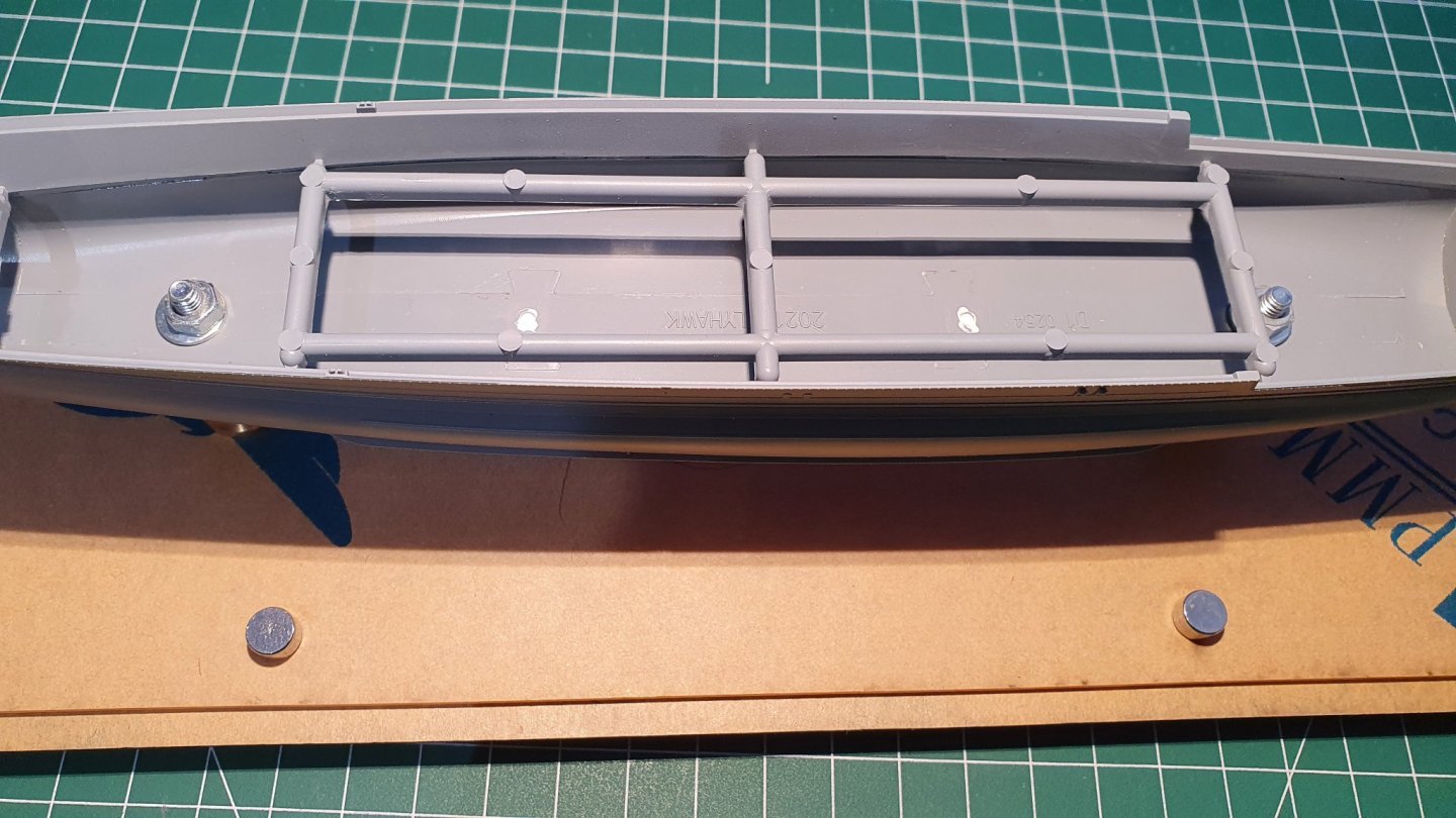
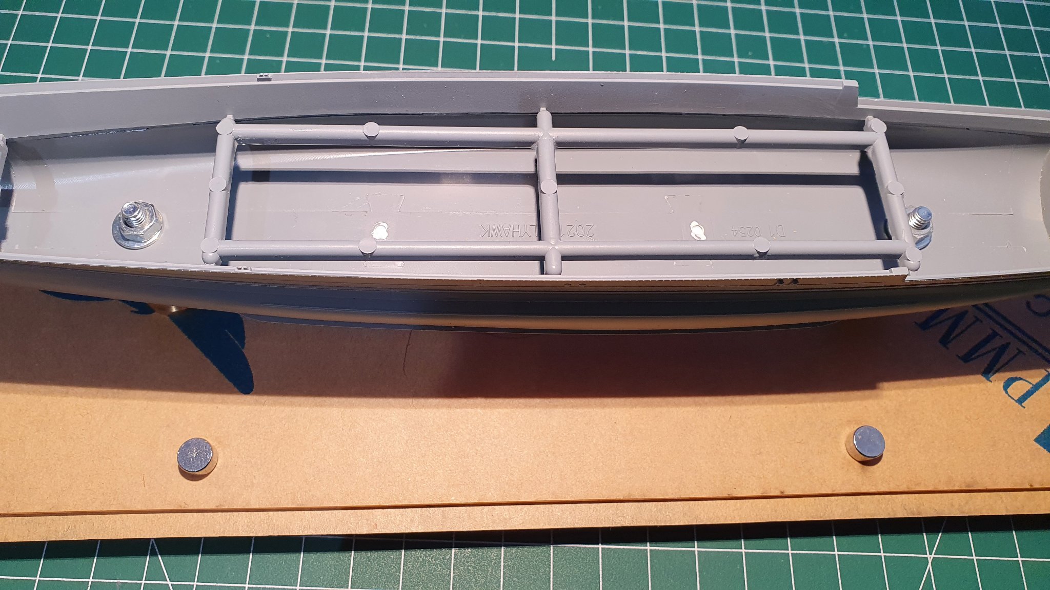
Am needing to be super careful now with the sequence of the build. I notice that the wooden (main) deck has no cut-outs for the breakwaters meaning the deck will need to be fitted first and the breakwaters added later. There are cut-outs for all the moulded detail on the deck and for all the tiny parts that need to be added once the deck is in place. Unlike the wooden decks of some bigger scale ships, I can see that Flyhawk have already cut out all the openings needed to fit the deck. This should make the process a lot less time consuming. BUT, before the deck can be fitted I need to mask and paint the moulded deck detail (got the full FL masking set). I'm masking to avoid there being a layer (or two) of paint under the wood of the deck which may allow the deck to lift here and there over time. The prop shafts and rudder have been added and the glue left to dry overnight so the next task will be to give the hull halves and decks a good scrub with detergent and an old toothbrush to remove any traces of grease from my fingers and the mould and when dry it's airbrush time with the primer. I decided on black primer to make it easier to see that I have covered all the areas of grey plastic that need to be painted. I will prime the hull too and after several thin coats of primer have dried I intend to proceed as follows.
I'll airbrush a thin stripe of black where the bootline will be then once dry I'll mask the bootline with 3mm tape, mask off the upper hull and spry the lower hull (dark grey!). Then, leaving the 3mm tape in place, I'll mask the lower half and spray the upper hull and deck detail with Admiralty Dark Grey 507A courtesy of Lifecolor. I chose this sequence so that it will only be the length of 3mm tape that will need to be removed from the paint surface.
Height of the boot line on the original was, I believe, 8ft which, at 1/700, equates to 3,48mm. 3mm is close enough for me and looks about right to my eye at least. I suppose I could try cutting 4mm tape down to 3,5 before fitting but to keep it perfectly parallel during cutting might prove difficult.
If anyone has comments/suggestions/warnings on how I'm proceeding then please do comment - this model requires higher skill levels than I am used to and I'm very much leaning as I go along (not obvious is it?!!!!!!), so any advice is welcome.
- mikegr, king derelict, Canute and 3 others
-
6


![20211003_191200[1].jpg](https://modelshipworld.com/uploads/monthly_2021_10/280821196_20211003_1912001.jpg.56a492205f8725f42405451808f032a2.jpg)


Prinz Eugen 1942 by CDW - FINISHED - Trumpeter - 1:700 Scale - PLASTIC
in - Kit build logs for subjects built from 1901 - Present Day
Posted
They look good to me and a neat solution.
I've ditched ideas to add the brass barrels to Hoods 5,5" secondary armament (see my build log). There are times when 'gilding the lilly' just doesn't make sense.