
Thukydides
-
Posts
1,369 -
Joined
-
Last visited
2 Followers


About Thukydides

Recent Profile Visitors
4,852 profile views


-
 Thukydides reacted to a post in a topic:
HMS Surprise 1796 (prototype) by James H - Vanguard Models - 1:64
Thukydides reacted to a post in a topic:
HMS Surprise 1796 (prototype) by James H - Vanguard Models - 1:64
-
 Thukydides reacted to a post in a topic:
USS Tennessee 1869 by Keith Black - scale 1:120 - Wood Hull Screw Frigate - ex Madawaska 1865
Thukydides reacted to a post in a topic:
USS Tennessee 1869 by Keith Black - scale 1:120 - Wood Hull Screw Frigate - ex Madawaska 1865
-
AJohnson reacted to a post in a topic:
HMS Perseus by Thukydides - 1:64 - POB - Sphinx Class 6th Rate
-
Thukydides reacted to a post in a topic:
Chaconia by Javelin - 1/100 - RADIO - LPG Tanker
-
Thukydides reacted to a post in a topic:
Chaconia by Javelin - 1/100 - RADIO - LPG Tanker
-
Thukydides reacted to a post in a topic:
La Créole 1827 by archjofo - Scale 1/48 - French corvette
-
Thukydides reacted to a post in a topic:
HMS Surprise 1796 (prototype) by James H - Vanguard Models - 1:64
-
 Thukydides reacted to a post in a topic:
HMS RESOLUTION 1667 by KarenM - 1:48
Thukydides reacted to a post in a topic:
HMS RESOLUTION 1667 by KarenM - 1:48
-
Thukydides reacted to a post in a topic:
HMS Crocodile 1781 by Pirate adam - 1/48 scale - POF
-
Thukydides reacted to a post in a topic:
Christiania 1774 by TJM – approx. 1:67-1:64 – Danish Light Frigate based on Vanguard Models HMS Sphinx
-
Thukydides reacted to a post in a topic:
HMS Bellerophon 1786 by AON – scale 1:64 – 74-gun 3rd Rate Man of War - Arrogant-Class
-
glbarlow reacted to a post in a topic:
HMS Perseus by Thukydides - 1:64 - POB - Sphinx Class 6th Rate
-
Ryland Craze reacted to a post in a topic:
HMS Perseus by Thukydides - 1:64 - POB - Sphinx Class 6th Rate
-
JacquesCousteau reacted to a post in a topic:
HMS Perseus by Thukydides - 1:64 - POB - Sphinx Class 6th Rate
-
 Thanks glenn, yes that is essentially my current conundrum. I have sketched out and am pretty clear on what needs to happen outboard, it is the inboard arrangement that I am still vascilating over. Also life has been busy so finding the time to sit down and figure it out has been difficult.
 -
mtbediz reacted to a post in a topic:
HMS Perseus by Thukydides - 1:64 - POB - Sphinx Class 6th Rate
-
Gregory reacted to a post in a topic:
HMS Perseus by Thukydides - 1:64 - POB - Sphinx Class 6th Rate
-
AJohnson reacted to a post in a topic:
HM Armed Cutter Sherbourne by Zvr - FINISHED - Vanguard Models - 1:64
-
Ryland Craze reacted to a post in a topic:
HM Armed Cutter Sherbourne by Zvr - FINISHED - Vanguard Models - 1:64
-
Paul White reacted to a post in a topic:
HM Armed Cutter Sherbourne by Zvr - FINISHED - Vanguard Models - 1:64
-
 Zvr reacted to a post in a topic:
HM Armed Cutter Sherbourne by Zvr - FINISHED - Vanguard Models - 1:64
Zvr reacted to a post in a topic:
HM Armed Cutter Sherbourne by Zvr - FINISHED - Vanguard Models - 1:64
-
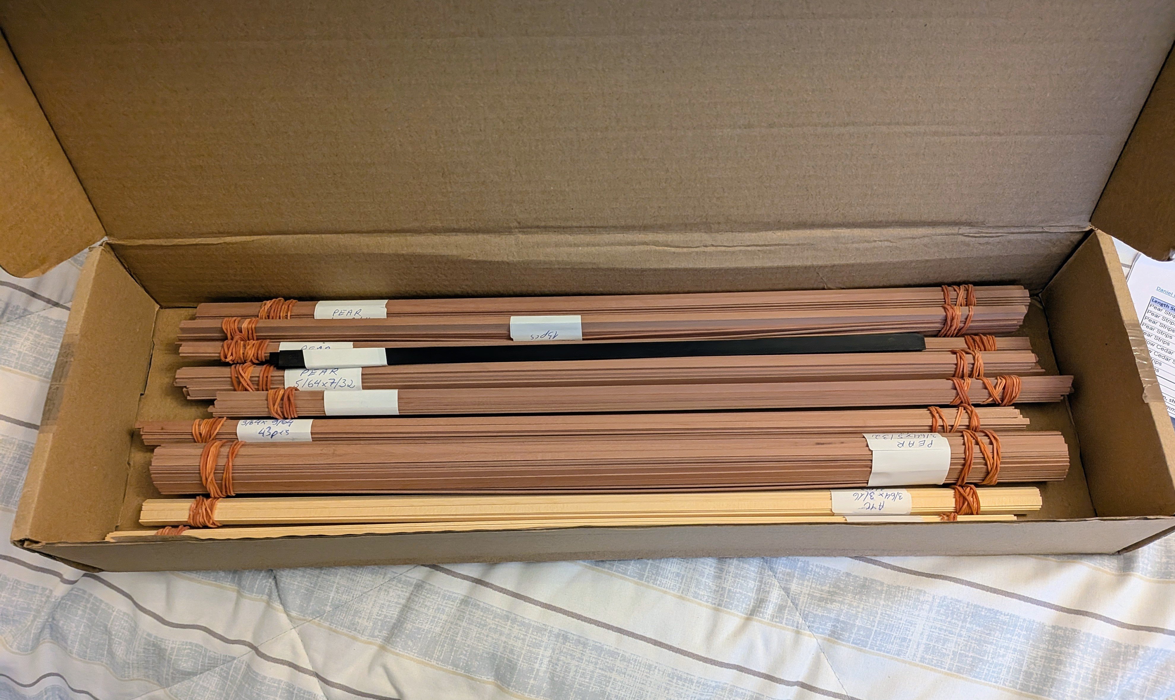
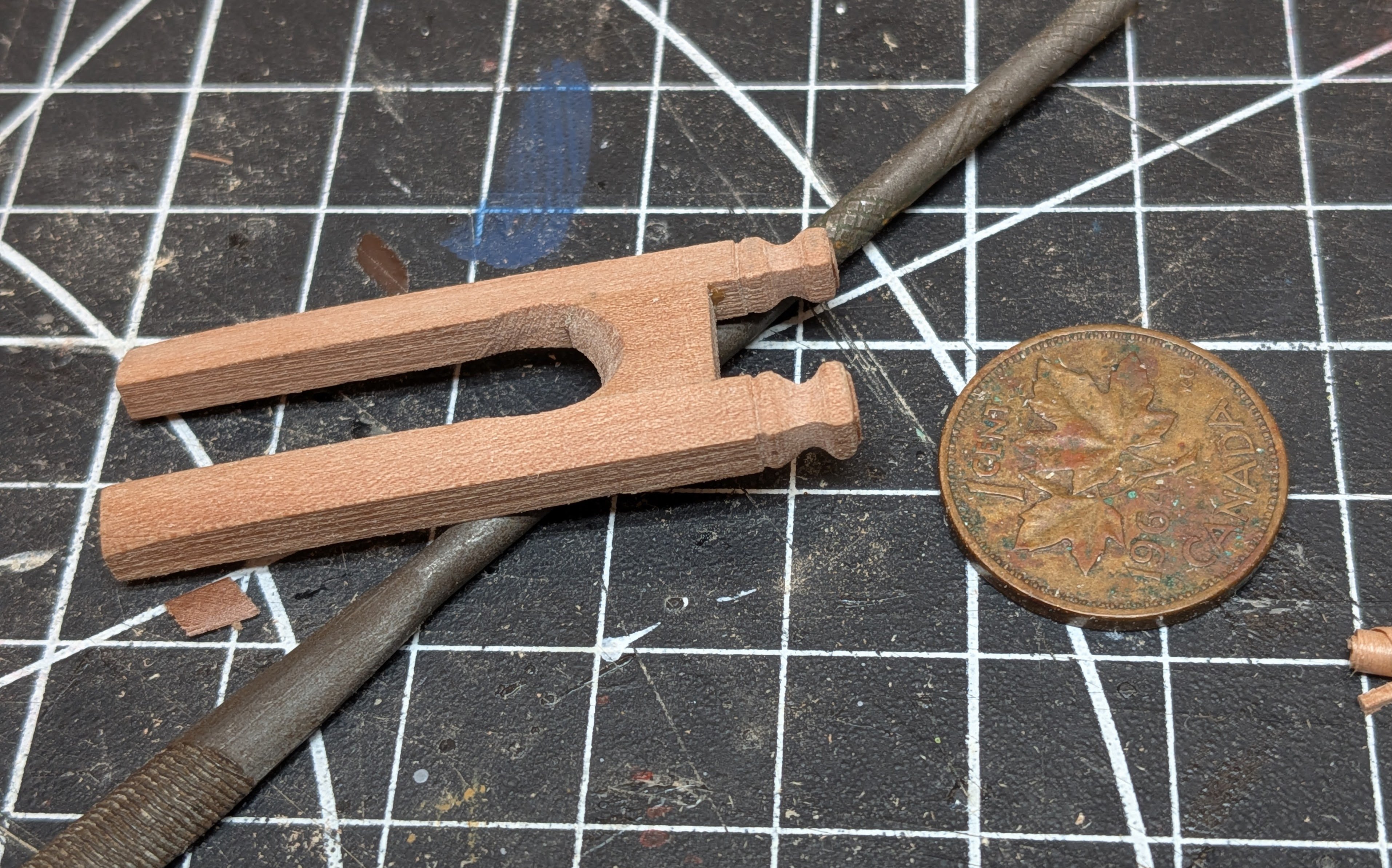
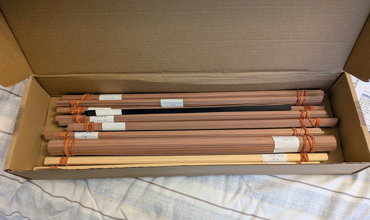
I thought I would give another minor update as I am still trying to decide what exactly to do with the bollard timbers. Below you can see my previous attempt (which has been consigned to the bin while I try to make a better more historically accurate set. I am finding myself vassilating between options, but I need to bight the bullet and just make a decision. I also received a shipment of wood strips today from @Wahka_est at hobbymill.eu to enable me to do the outer planking. The wood looks lovely and he also sent me some samples of black hornbeam which I really liked the look of. It won’t work for what I have planned with Perseus, but I am thinking future projects I just may decide to use it for the black parts.

-
Welcome, you have made a great choice for your first build. I also came to wooden ship modeling from plastic models and you will find some this translate well and others do not. I would highly recommend starting a build log. Good luck
-
I suspect in many such cases the sources just didn't show the details. Every primary source example I have found which intended to be accurate at that level of detail shows some sort locking mechanism. Granted I mostly look at British stuff. Also every contract I have read makes mention of locking the wales together often specifically mentioning the joint they are meant to use. That is not to say that some of the strakes on the wales may have been joined in butt fashion, just that some of them would necessarily have been locked together.
- 148 replies
-
- 3
-
-
- Christiania
- Vanguard Models
- (and 1 more)
-
A scarf joint is much more secure. In addition to what you can see there was also an indent in the scarf that held the planks together. It would impart much more latera strength. The wales were the main structural part of the hull holding everything rigid (hence why they were thicker). The scarf essentially locked the planks together. They were frequently used on joints all over the ship that required more strength or were more structurally important. For example the keel would have had scarfs to hold n the pieces together, you just don't see it because they are facing vertical instead of horizontal in this case. If you consider the size of these things the scarf is not actually that small and there is plenty of room for a treenail. That being said scarfs were not the only thing used to lock the planks together. British shipwrights (particularly for smaller ships like the sphinx class, which the kit here is based on), would often use what is called top and butt planking. It essentially uses planks in the shape of a lopsided anchor stock to lock two strakes together. Of note they often also used this for the planking under the wales as well.
- 148 replies
-
- 4
-
-
-
- Christiania
- Vanguard Models
- (and 1 more)
-
Great to see you back at it. I look forward to seeing what you make of this given your previous work.
-
Ok thanks, I will have to some more digging. Like everything it seems like things are always more complicated than seen at first glance.
-
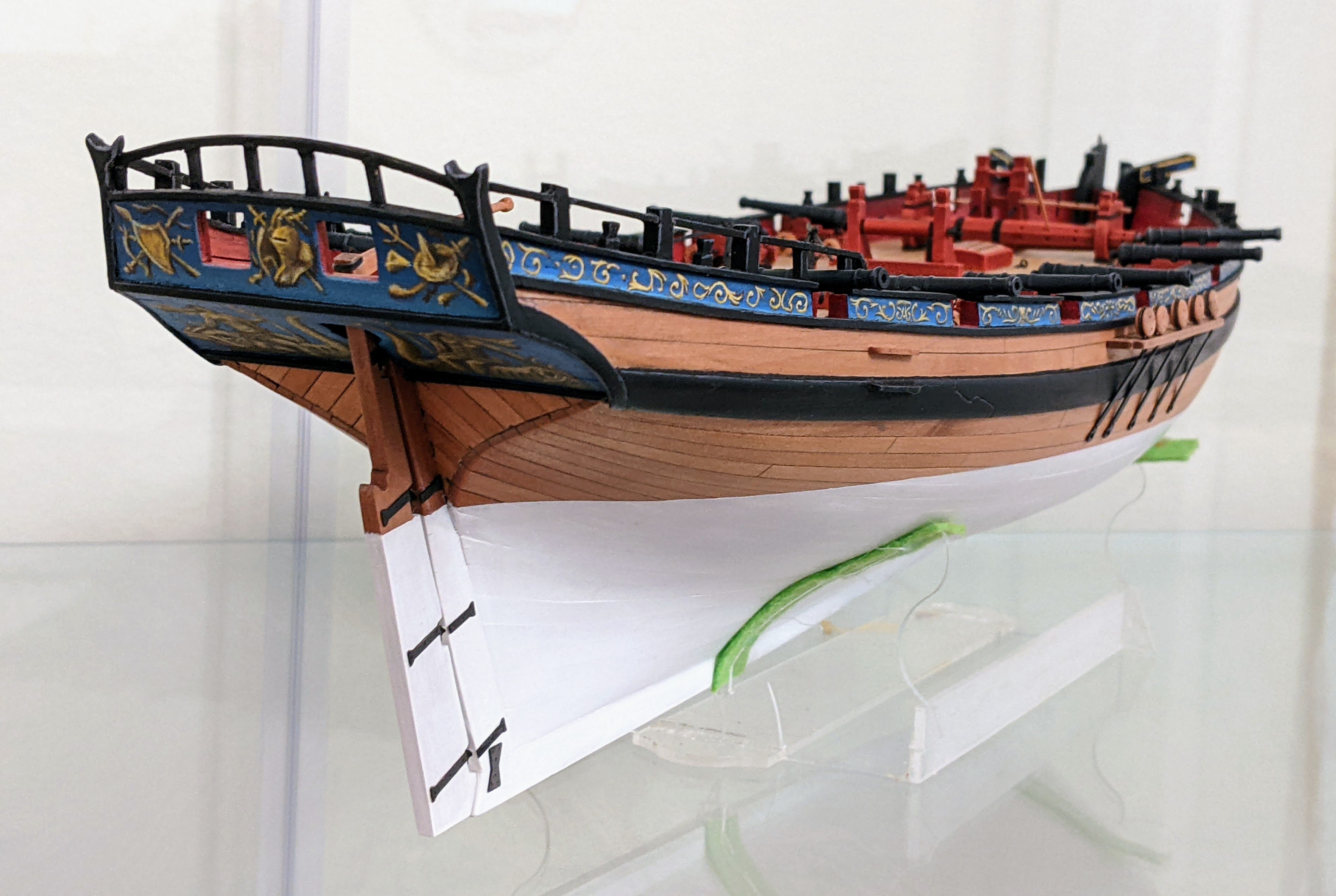
I am currently working on the bollard timbers / knight head and I have run into some confusion. I am hoping that someone has some insight to share Many of the fully framed models I see on this site have the bollard timbers jut out just below the top of the stem so that the planking ends at the side of the timbers instead of in the rabet of the stem. For example see the below explanation from Chuck’s Winchelsea plans, but this process is replicated on others such as @druxey’s swan class practicum and the HMS Naiad by Ed Tosti. https://syrenshipmodelcompany.com/resources/Chapterone (1).pdf I would normally not question the methods of these very skilled individuals, but when I look at the plans for Perseus and the other sphinx class the knight head seems a bit thin and I see little evidence for this extension. For example: The framing plan for sphinx seen here does not appear to show a hard extension. If the bollard timbers are proud of the planking, it appears to be a gradual transition. The as built plans for sphinx ships (many could be found, but here is one example) are similarly unclear, but some appear to show the planking line continuing all the way up to the top of the bulwarks. The planking expansion for sphinx does show a gap at the bow (see here), but it is much too high. The top of the stem is roughly level with the top of the foremost port. As you can see in the expansion the gap does not start until two strakes higher than that. This suggests to me that this gap is only there to allow the top of the knight head to stand free. The AOTS Pandora book depicts pandora with planks over the bollard timbers. Now I don’t normally consider this book reliable (I have already found too many innacuracies), but I am wondering if their assumption in this regard came from somewhere. Alex M’s excellent sphinx model appears to plank over the bollard timbers. So in conclusion I am wondering if the practice of having the bollard timbers standing proud of the planking and having the planking end against them was a universal practice or if it depended on the ship. Is this just somthing that they didn’t bother to depict on the plans because it was always done and there was no need to show it. Are there some examples (particularly contemporary ones) that you know of where the planking went over the timbers?
-
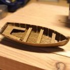
Now that is really interesting. I would have thought they still would have one (even just for transporting water or supplies back and forth). Out of curiosity, where did you find that detail?
- 4 replies
-
- 1
-
-
- Adder
- Vanguard Model
- (and 1 more)
-
I have a copy of May's "The Boats of Men of War", he talks about the boats carried by various ship types. I will take a look and see what he says for brigs of the period when I get home. Edit: Steel lists ropes for a launch and one of a pinnace/yawl/cutter though that doesn't tell you the sizes. https://maritime.org/doc/steel/tables/pages/138-BrigOf160Tons.php
- 4 replies
-
- 1
-
-
- Adder
- Vanguard Model
- (and 1 more)
-
Welcome to the forums. Your models look great. I have a soft spot for Alert as it was my first wooden model. I will be following along to see how this progresses.