Paul Le Wol
-
Posts
1,062 -
Joined
-
Last visited
Content Type
Profiles
Forums
Gallery
Events
Everything posted by Paul Le Wol
-
Hi Nando, welcome to Model Ship World. Perhaps the build logs of the Occre version of the Santisima Trinidad could be of some help to you.
-
Hi Phil, thank you very much!
-
Hi John, thank you. Its good to hear from you!
-
Hi Keith, thanks very much!
-
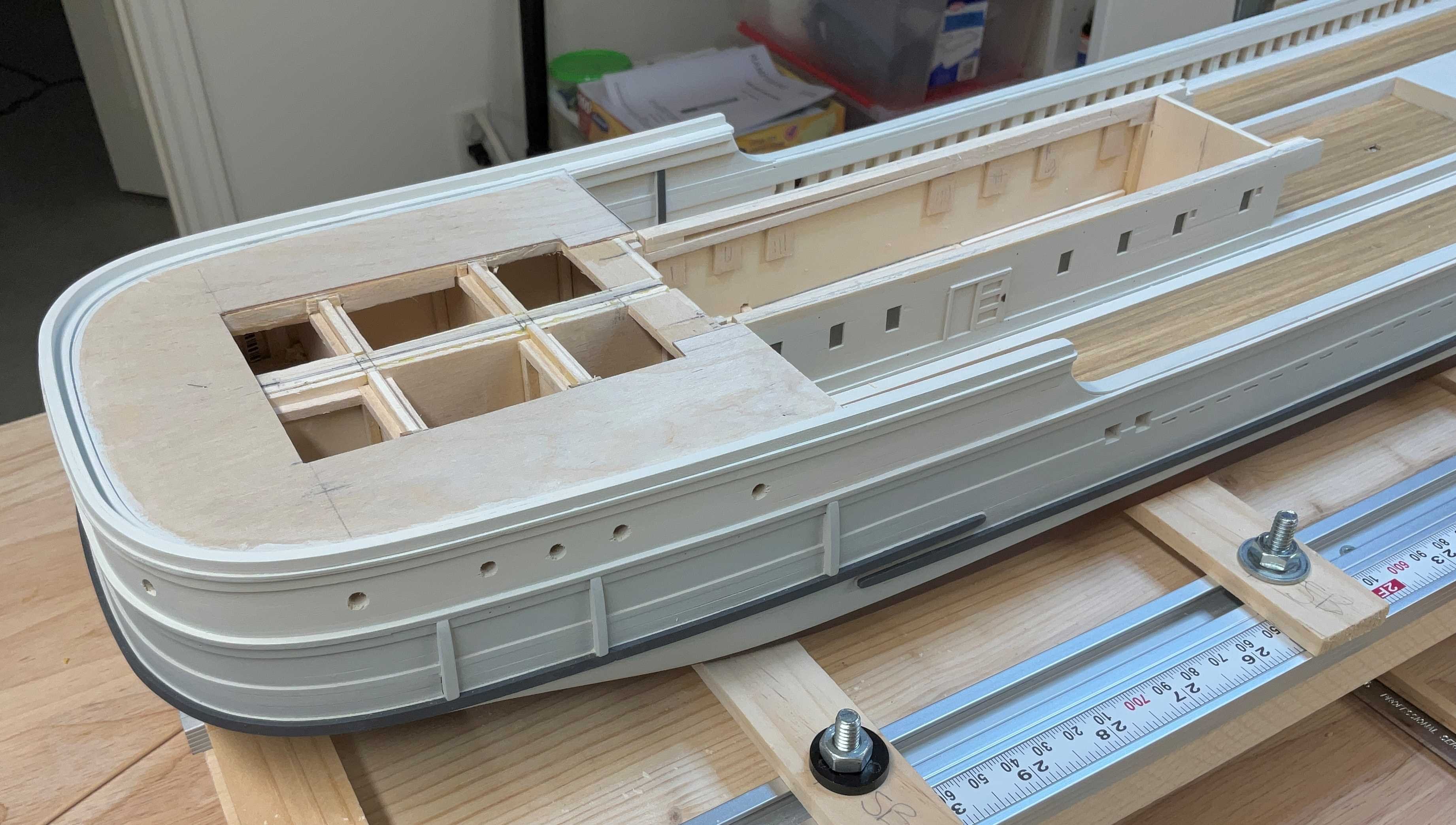
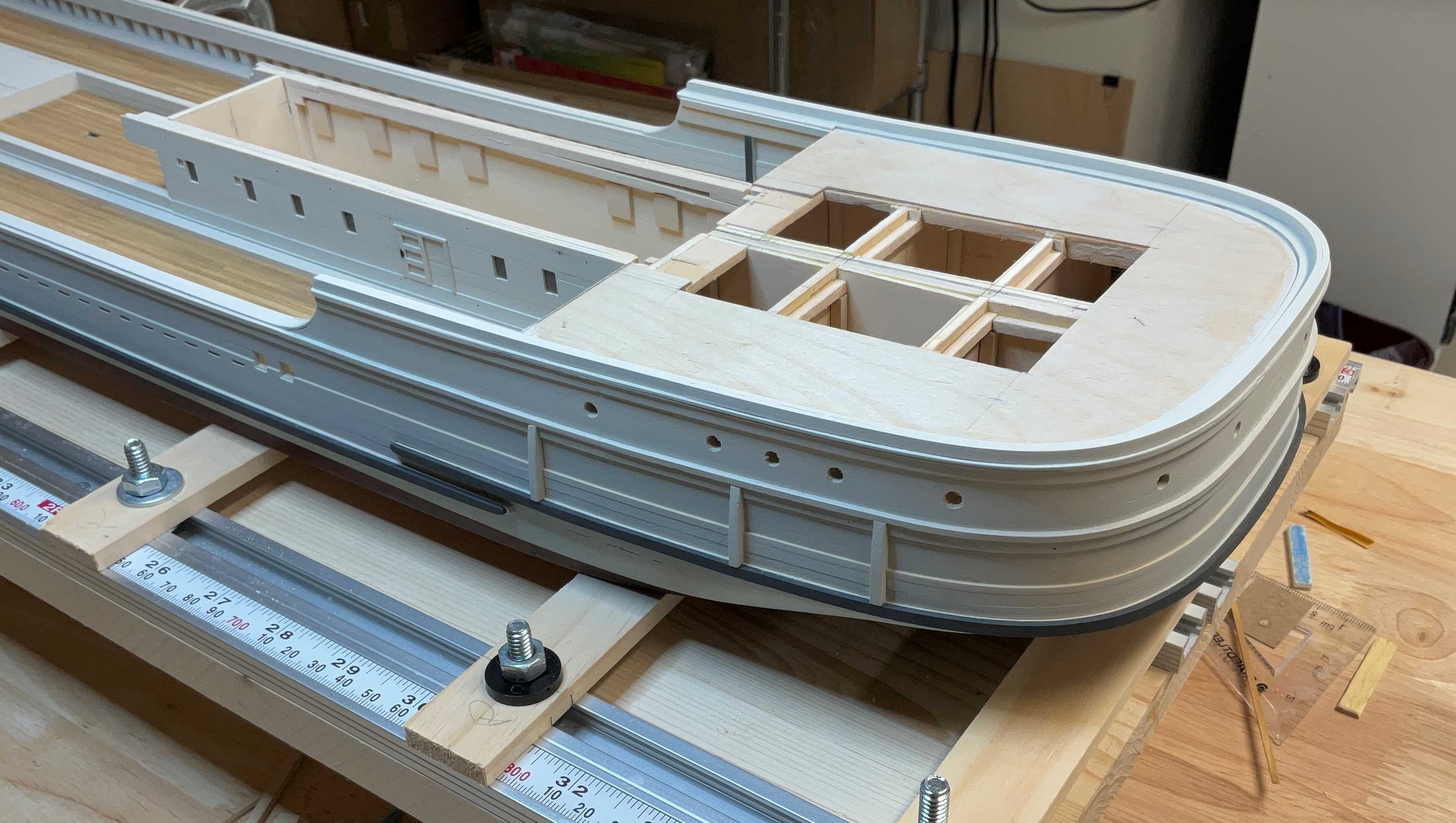
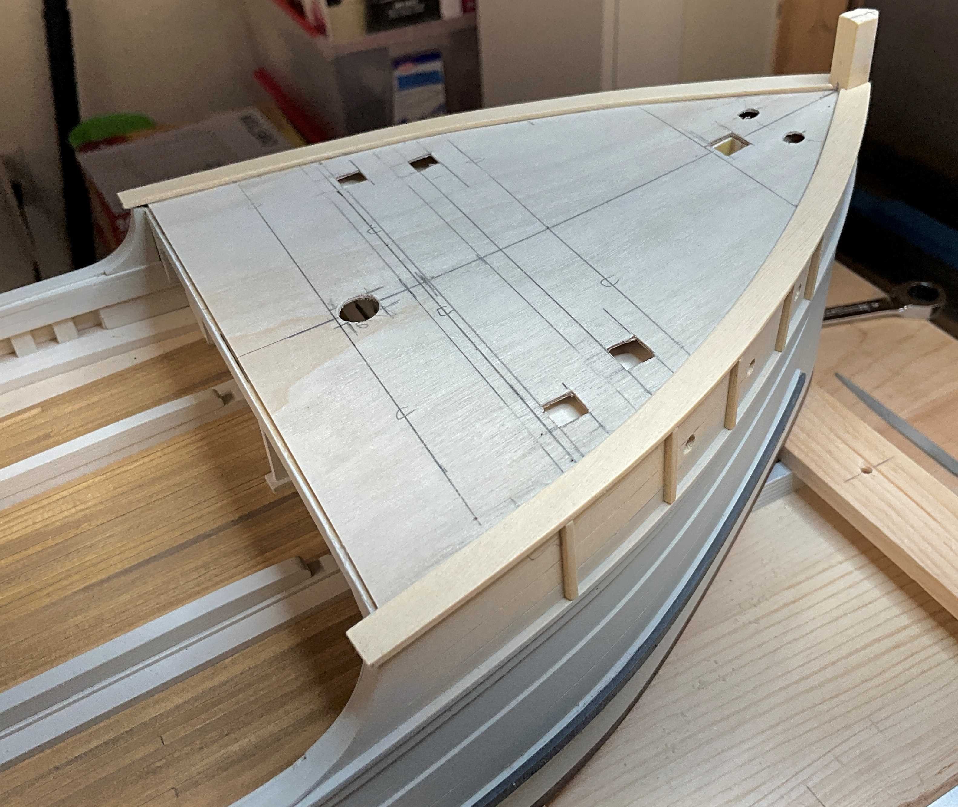
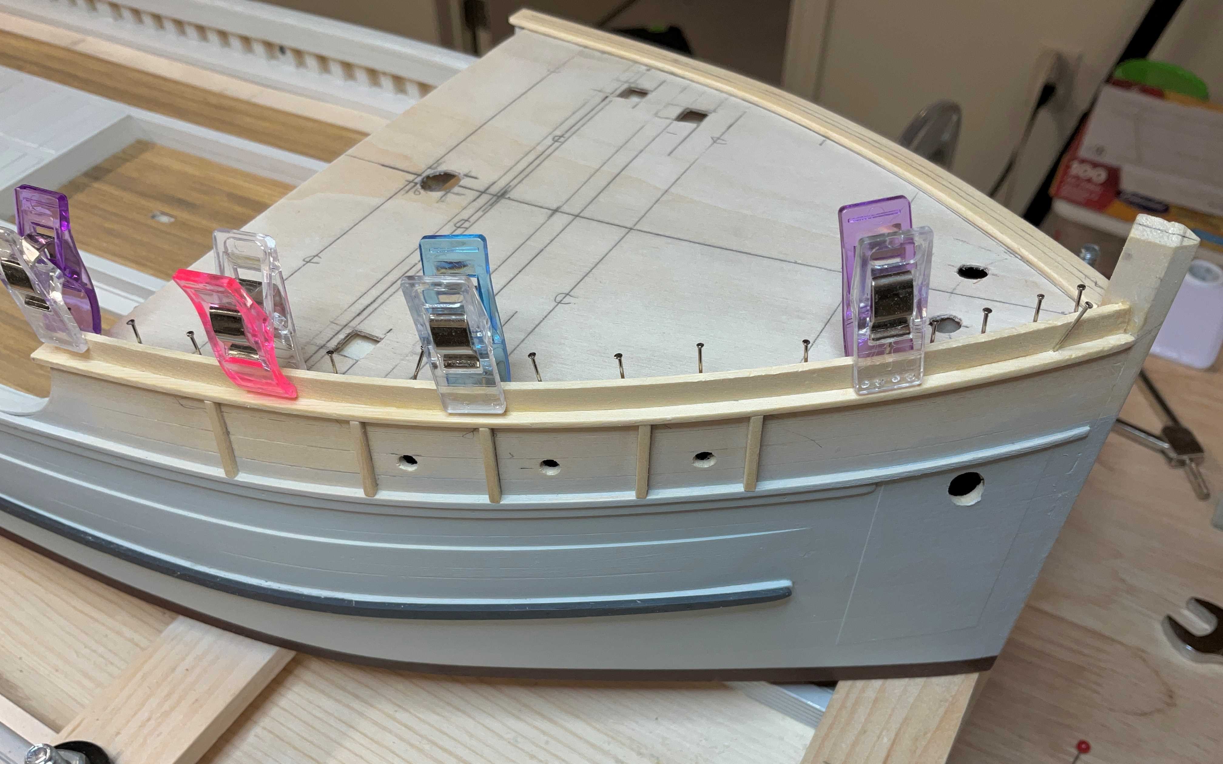
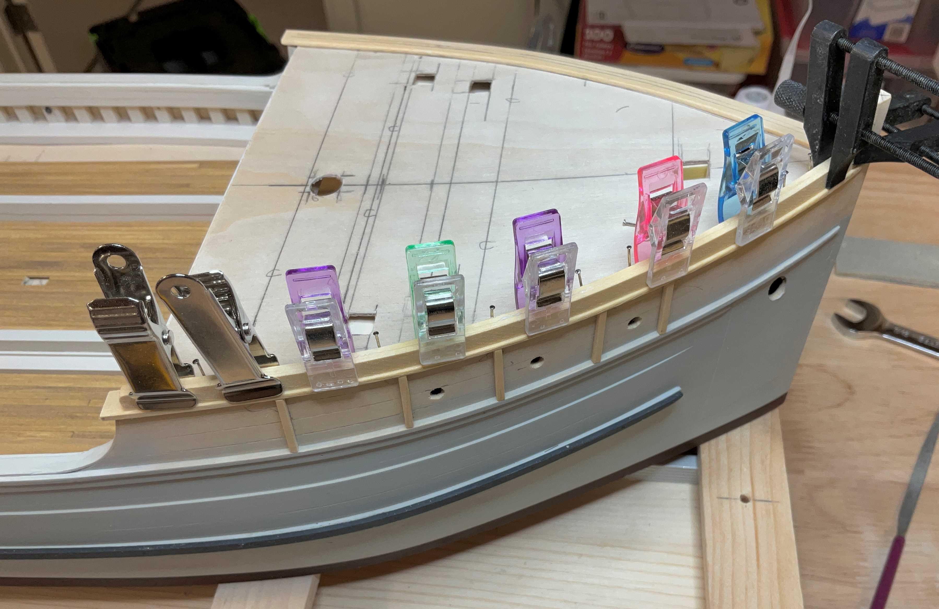
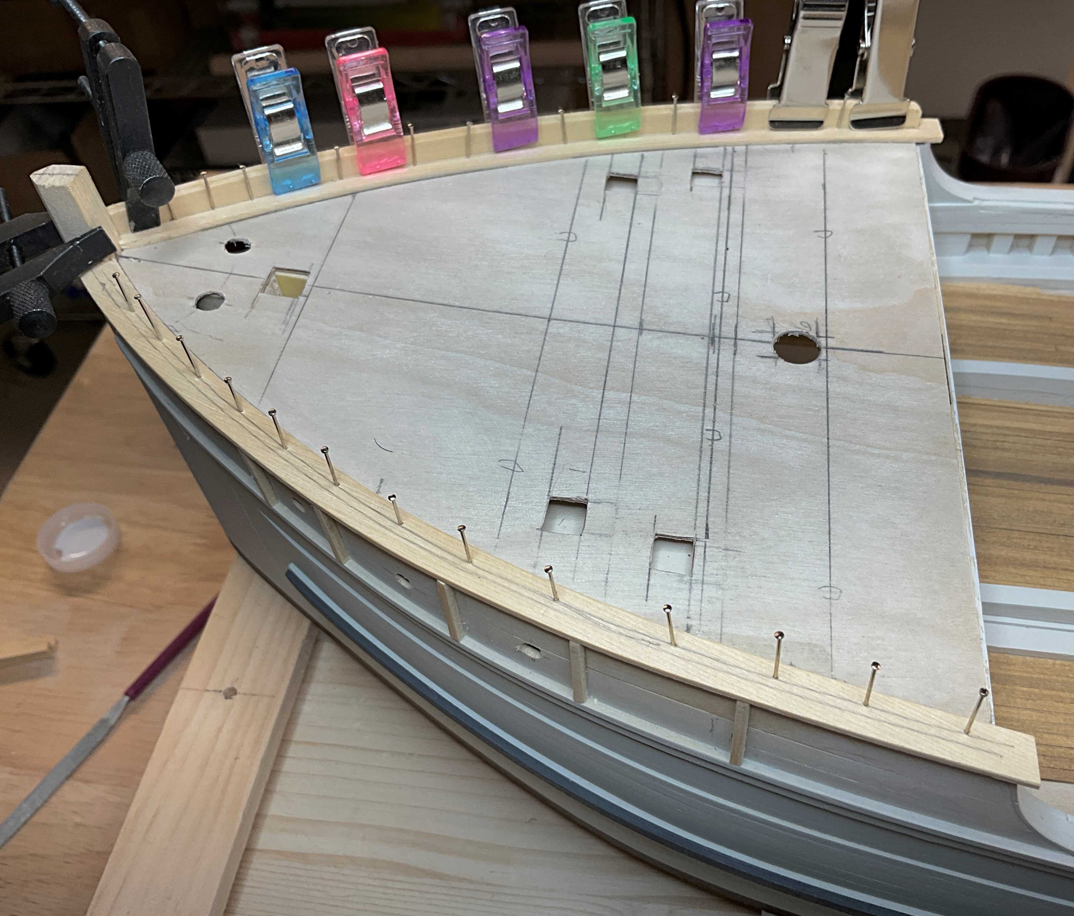
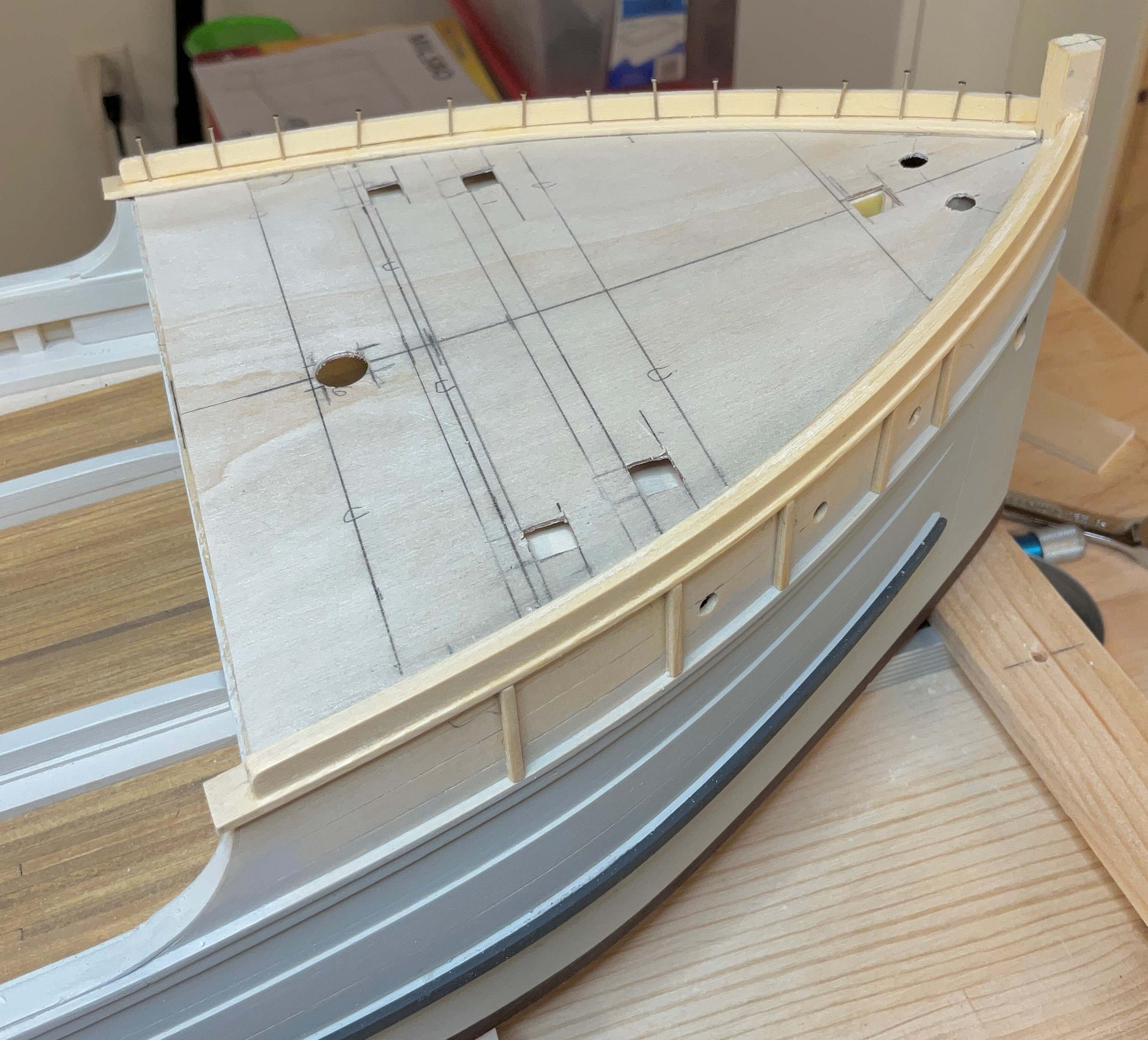
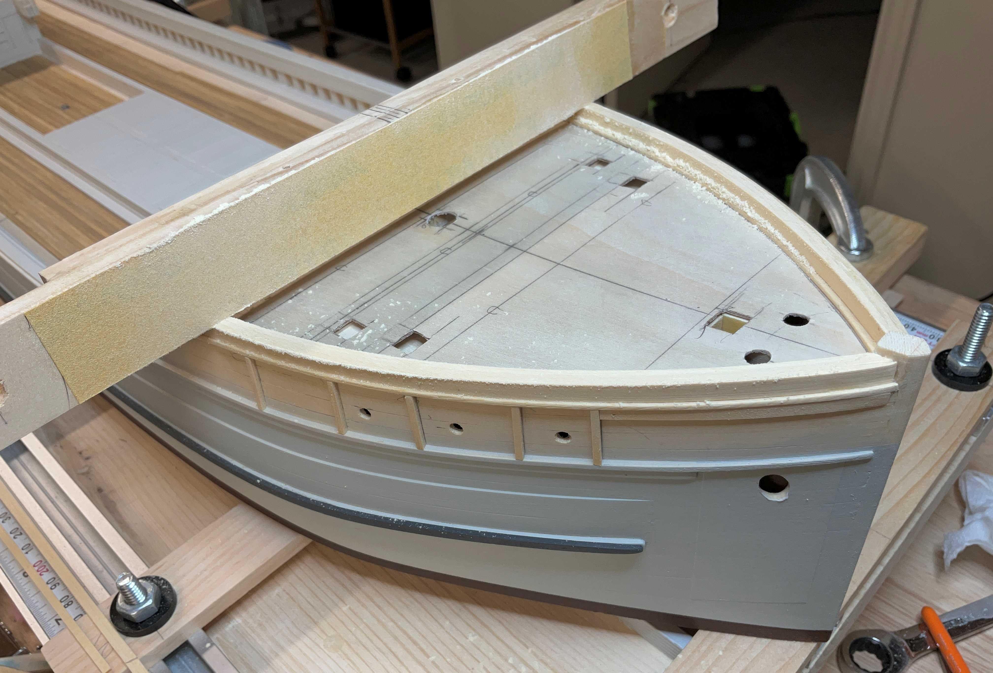
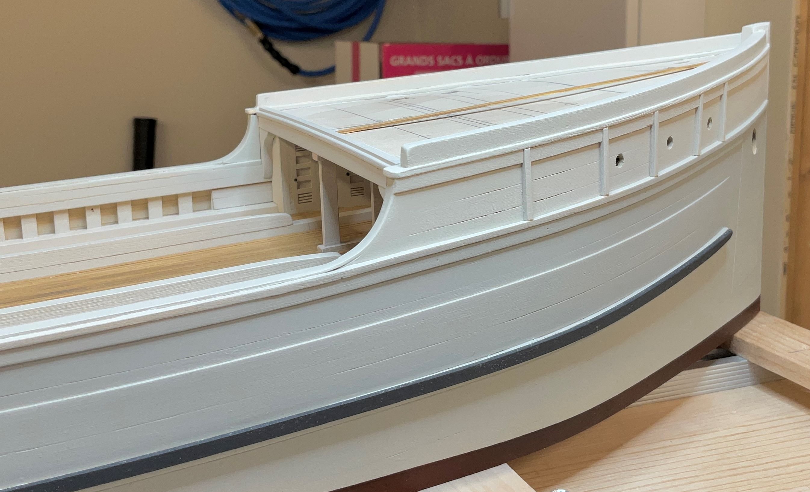
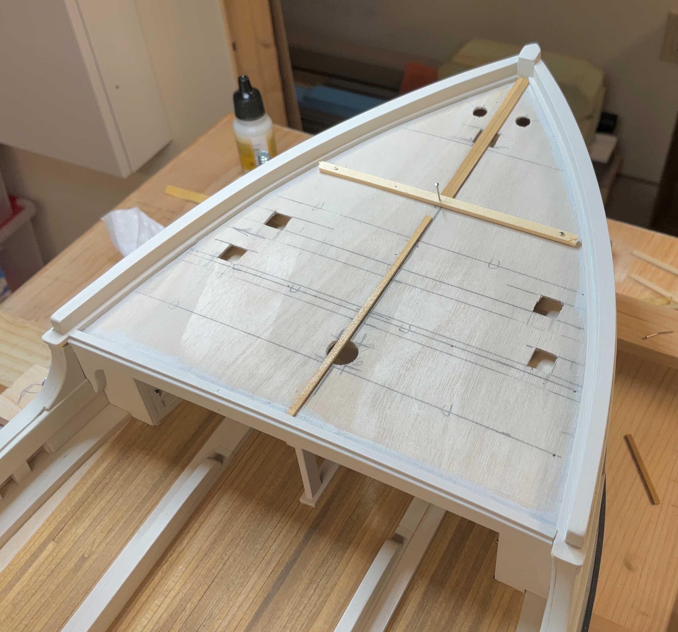
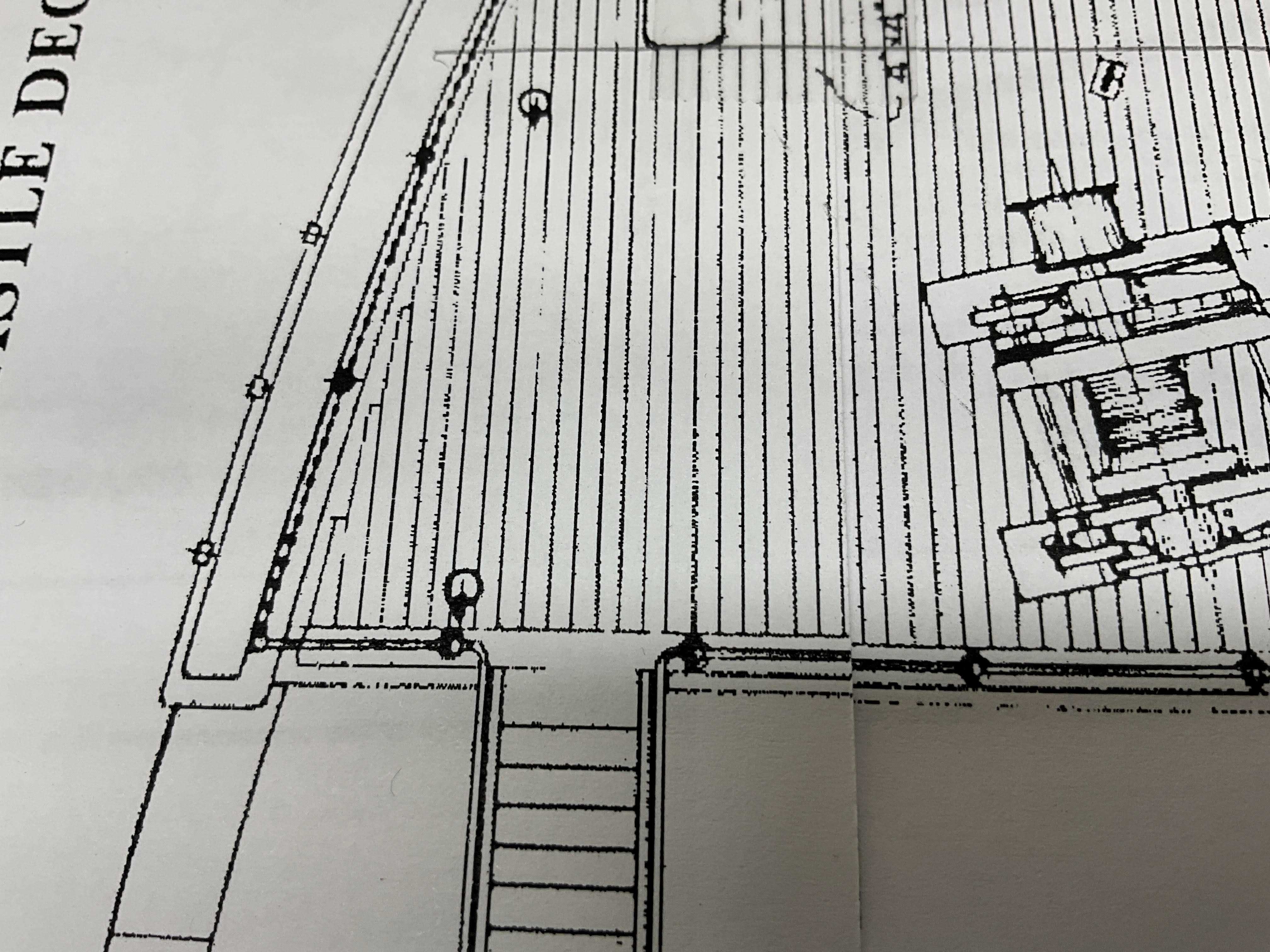
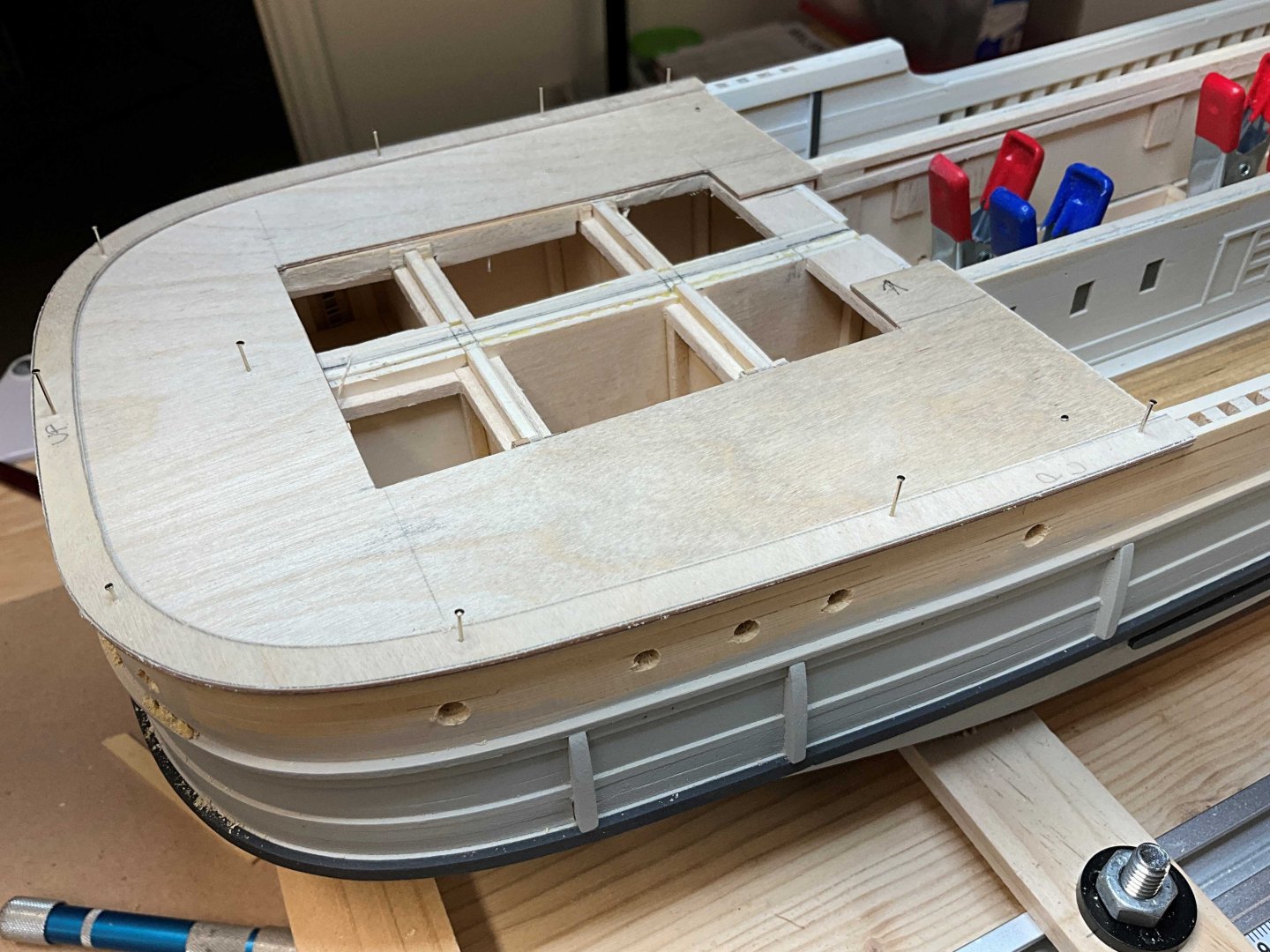
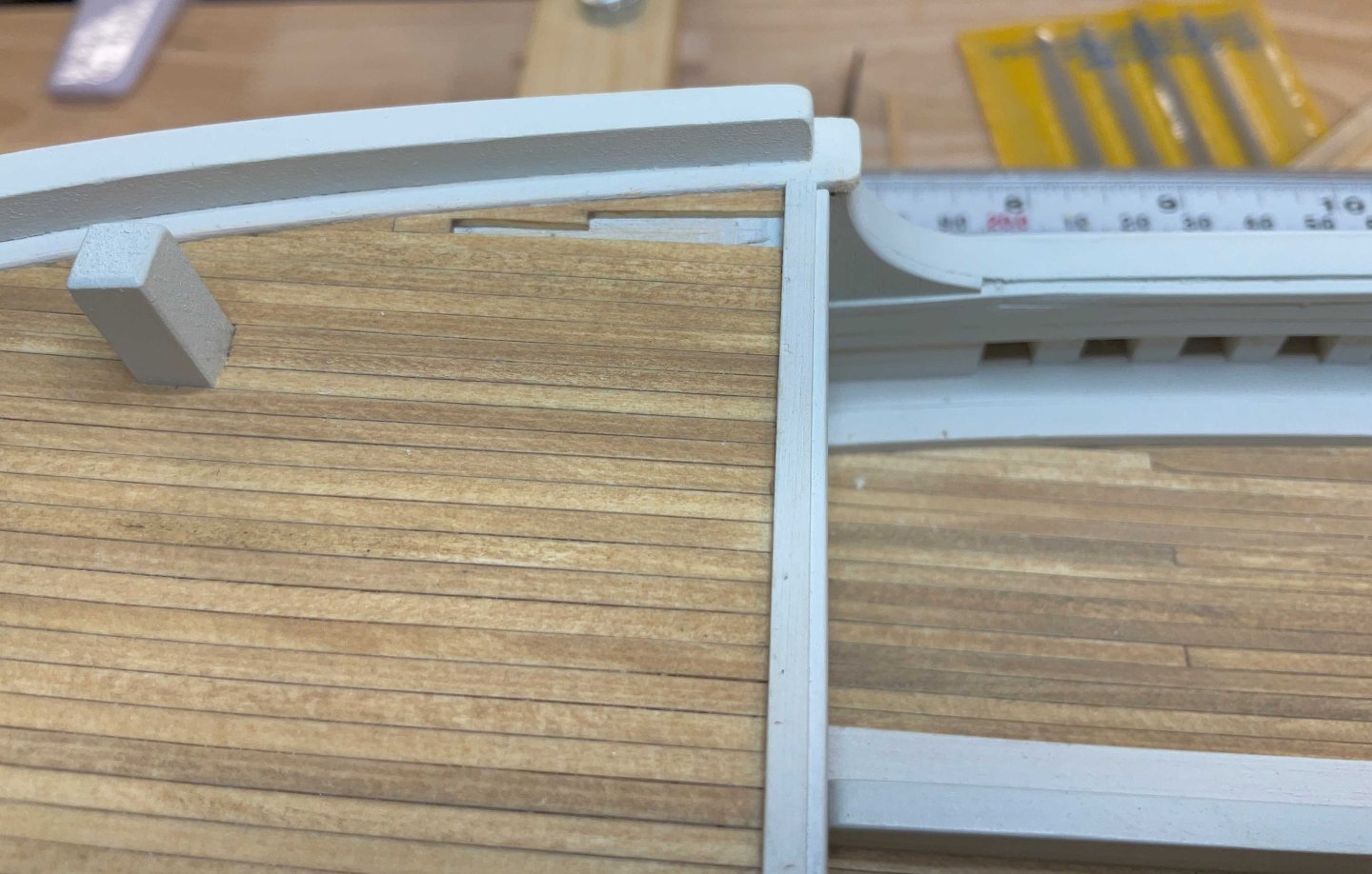
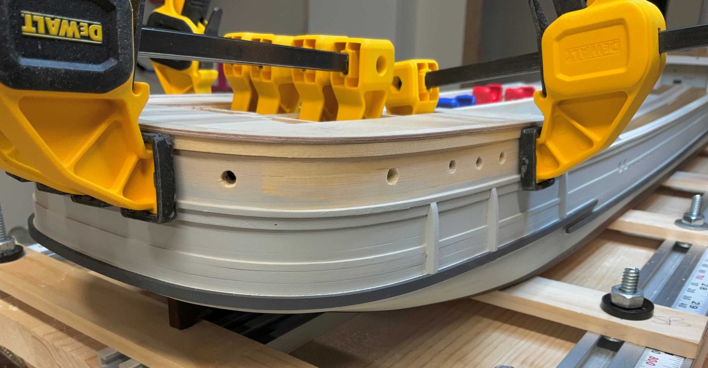
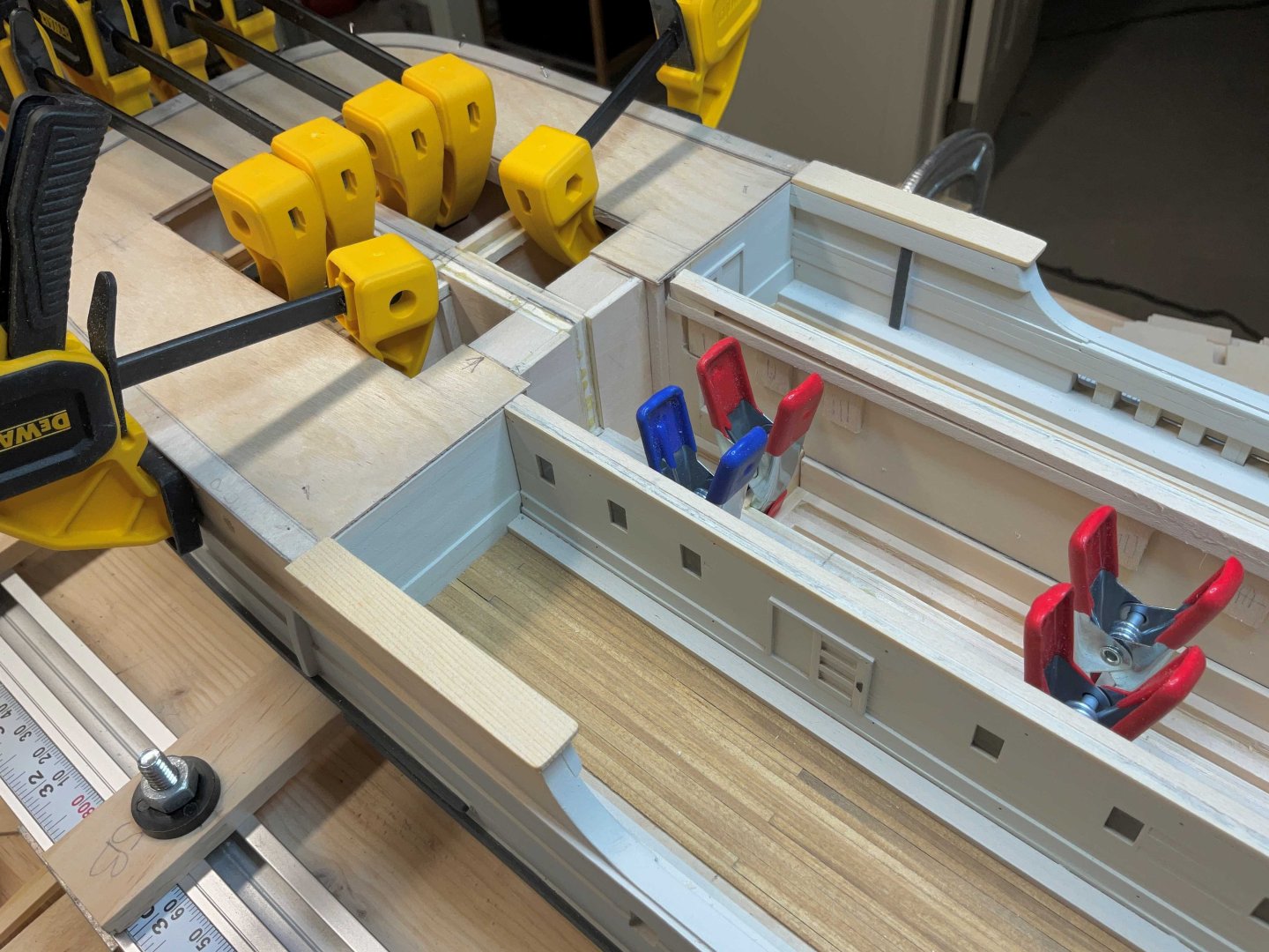
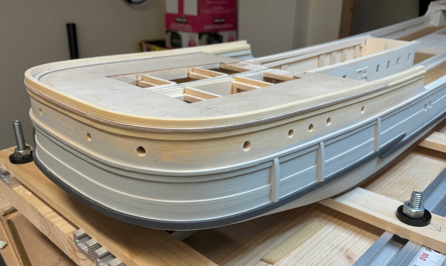
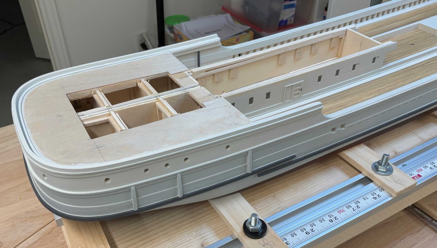
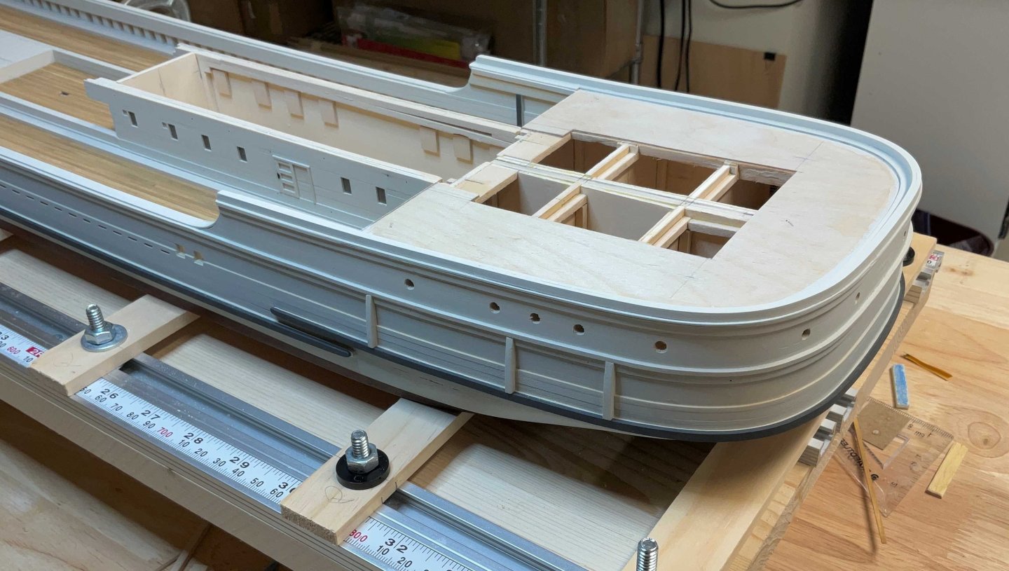
Hey Everyone, I hope all is good. Thanks to Everyone for the Comments and Likes. This update looks like more of the same only at the stern. I finished planking the forecastle deck. I managed to squeeze in 2 nibbed planks. The drawing shows 3 but because I'm using 5/64" wide strips instead of 1/16" wide strips everything gets thrown off a bit. The rough cut subdeck for the cabin deck was pinned to the hull and sanded back to within 1/16" of the bulwark planks using the small sanding block. The subdeck was then cut to accept the cabins and then glued in place. For the waterways a piece of 1/32" plywood was laid on top of the subdeck and the outboard edge of the subdeck was traced on to it. The outboard edge of the waterway was cut almost to the line and pinned on top of the subdeck. Then the inboard edge of the waterway was scribed on to the plywood using a compass stuck in a small block of wood that slid on the face of the bulwark planks. The inboard edge was cut and sanded back to the line and the waterway was pinned to the subdeck. Once everything looked okay the waterway was glued to the subdeck and the outboard edge was sanded back to the subdeck using the same sanding block The 1/32" x !/8" strip of wood that runs under the waterway was glued in place The coaming is made of two layers of 1/16" x 1/8" strips of AYC that were pre bent on the same mold as the rest of the stern planking. A line was scribed on the waterway to mark the inboard edge of the first plank and pins were inserted along this line. This plank was attached to the waterway with CA The outer plank was glued to the inner plank using white PVA After a bit of sanding the bulwark planks were painted Thanks for stopping by. The cabins are up next.


-
I have both of these tools and enjoy using them very much. On first use of the slicer it took me about 20 seconds to draw blood. Not the tools fault but my carelessness. I now keep a pair of tweezers handy to retrieve the cut pieces
-
Nice start to your build and build log!
-
Jacques, a very interesting read and some very interesting design changes!
-
Taubman’s Plan Service has them at taubmansonline.com. They are in the Rochester NY area
-
Craig, absolutely beautiful!
-
Hi druxey, thank you very much for your Comment!
-
Hi Phil, I did start hooding the planks too early. The next plank was going to be the one that is nibbed into the margin plank. I should change the first two hooded planks to regular planks. Thank you for pointing this out 👍
-
Yves, thank you so much for your support!
-
Hi Steve, thank you for posting the photo of your beautiful Willapa. I hope to see more. I had noticed the metal attached to the corners in Phil’s photos but for some reason I thought that they were added when she became a museum ship. I appreciate the information about the hardwood corners. There may be a few things that I let slide but overall I will try to be accurate. ( something I am not known for 😀) . Thank you so much for your Comment, I appreciate it very much!
-
Hi Keith, thank you for your kind words.
-
Gentlemen, thank you for your generous comments. They mean a lot to me!
-
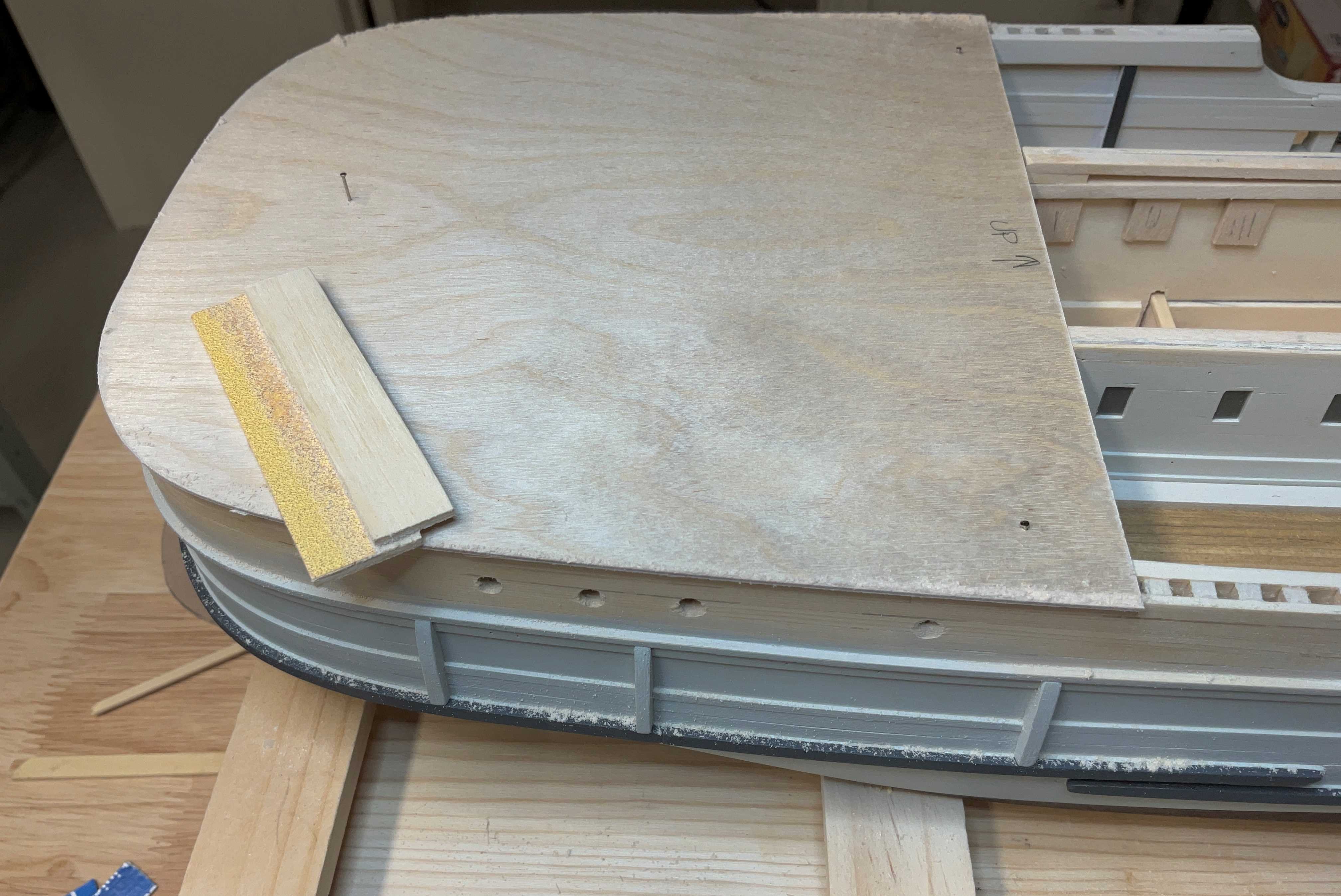
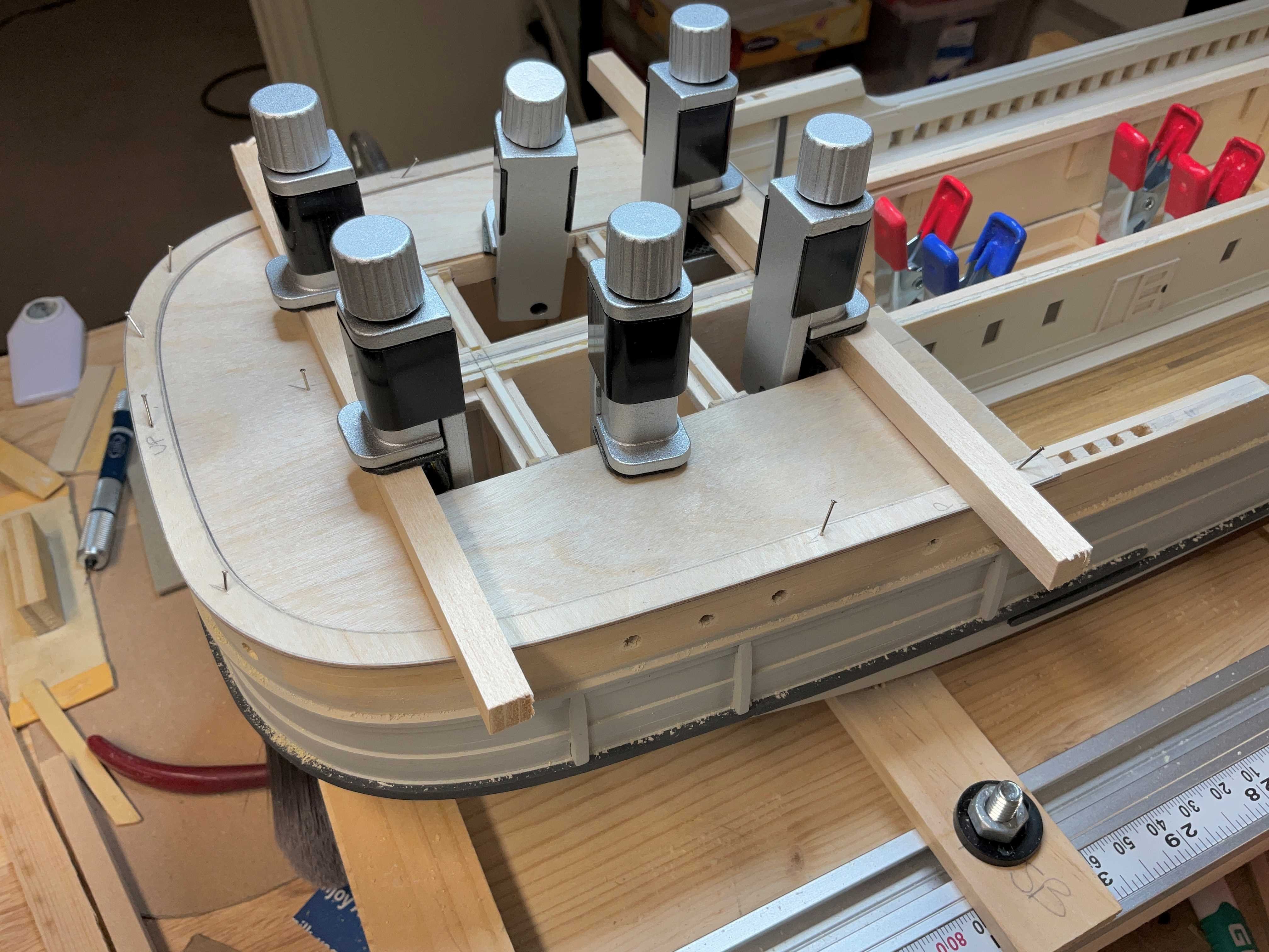
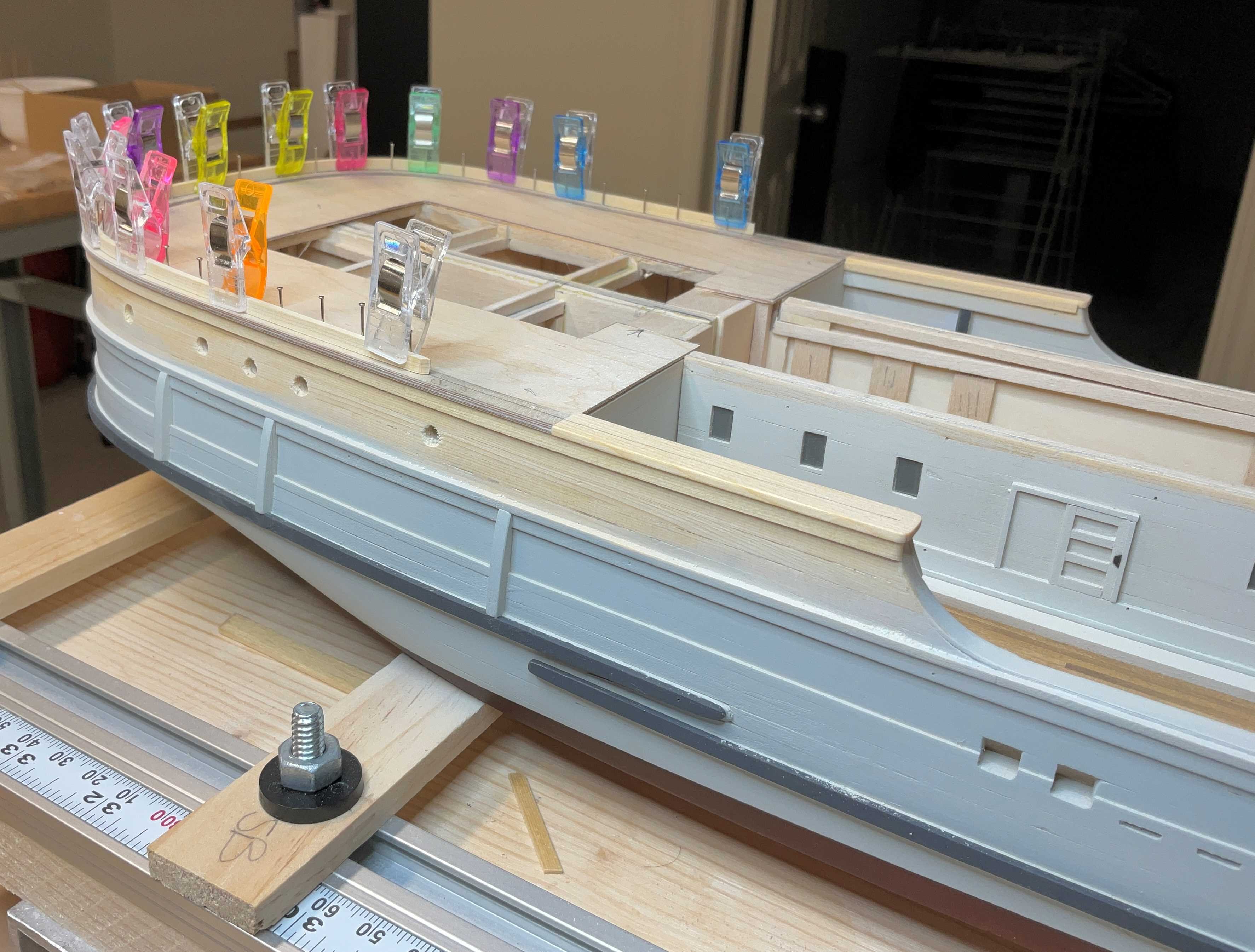
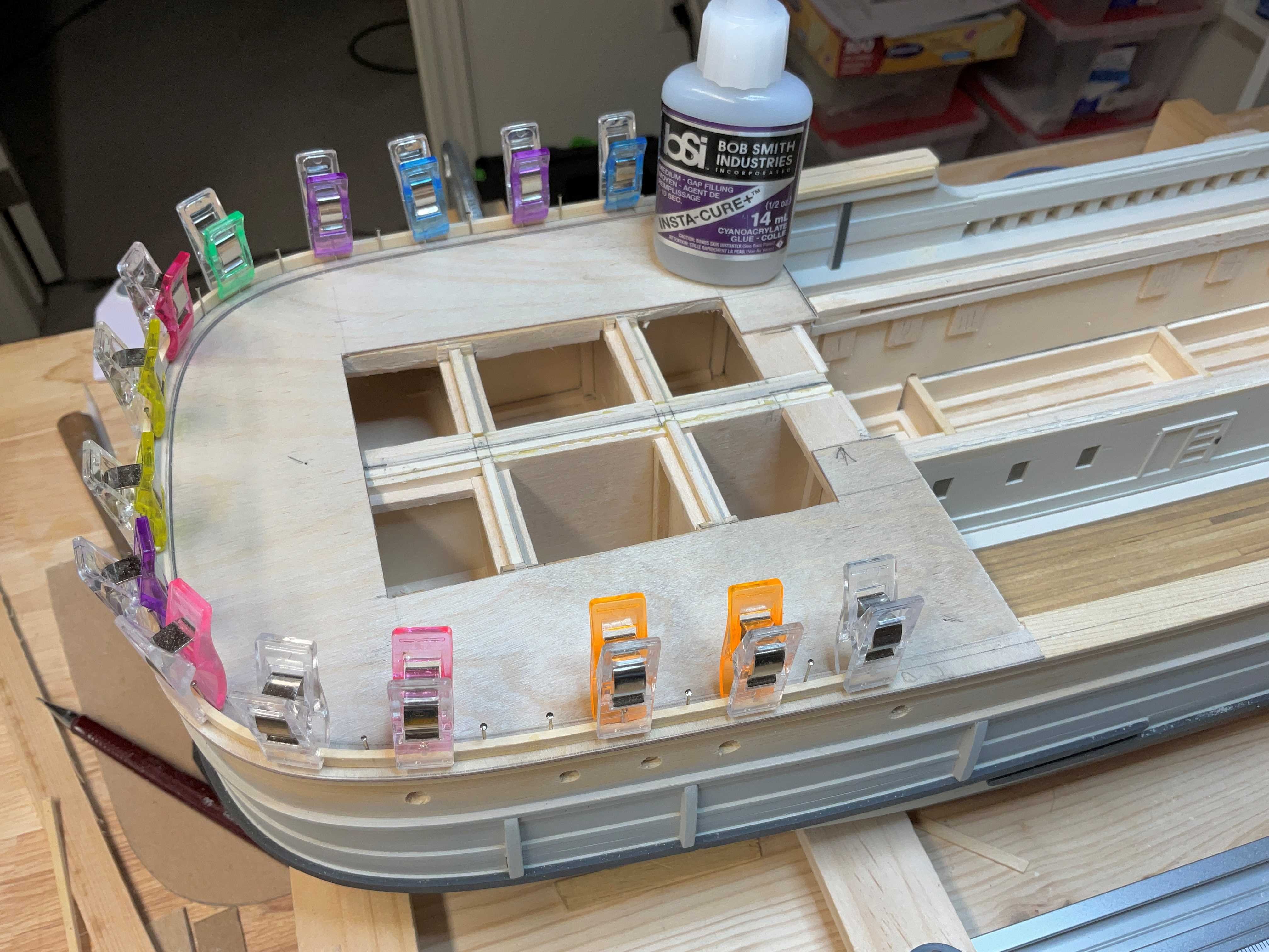
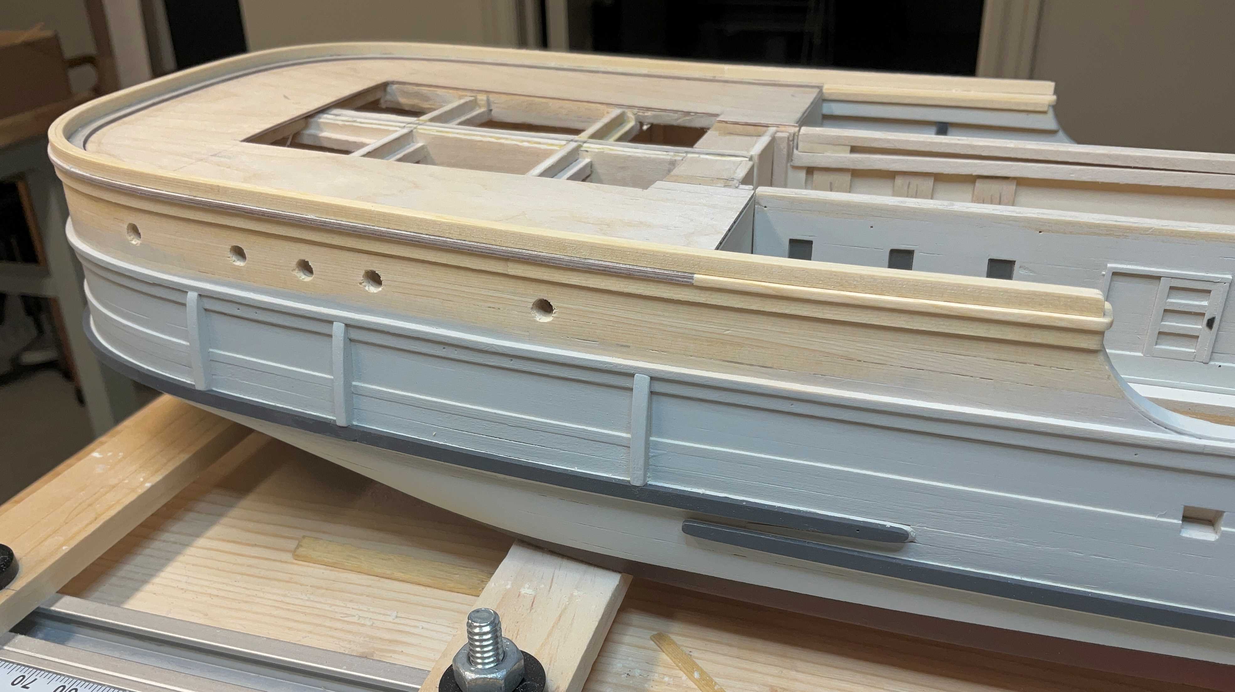
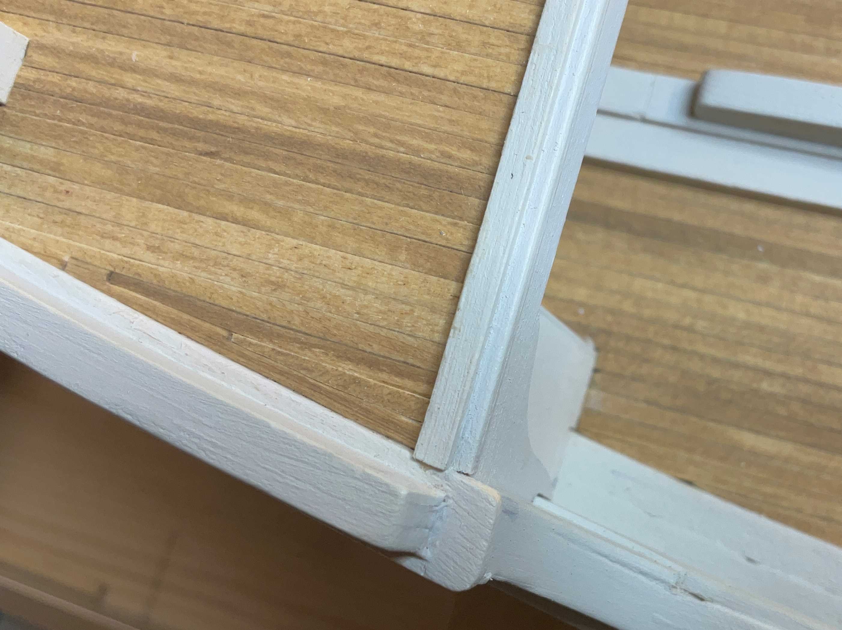
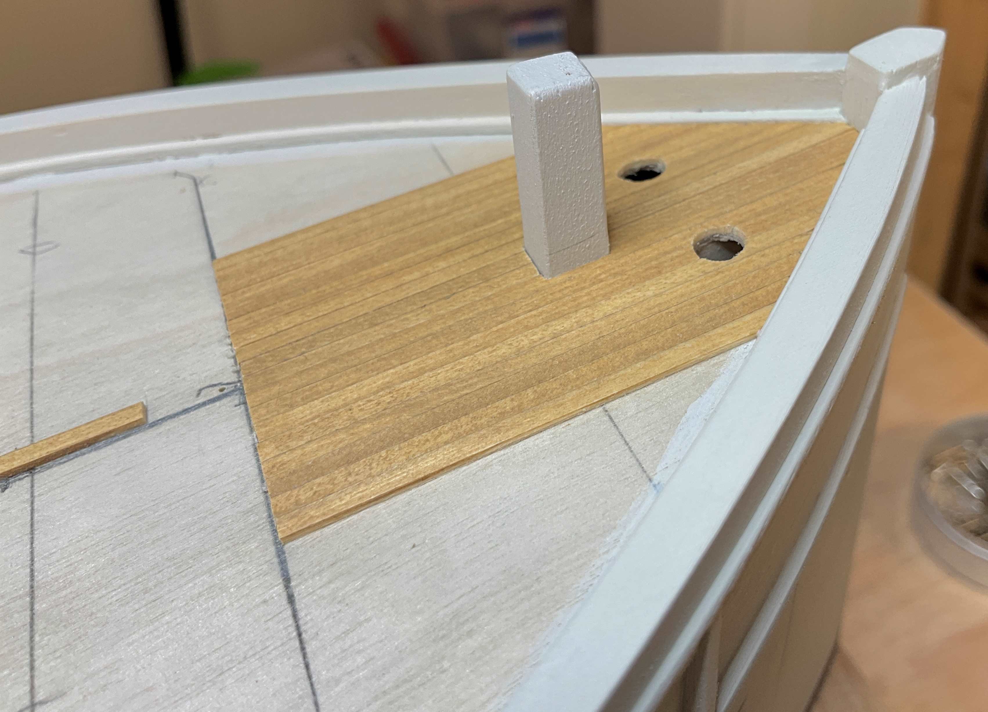
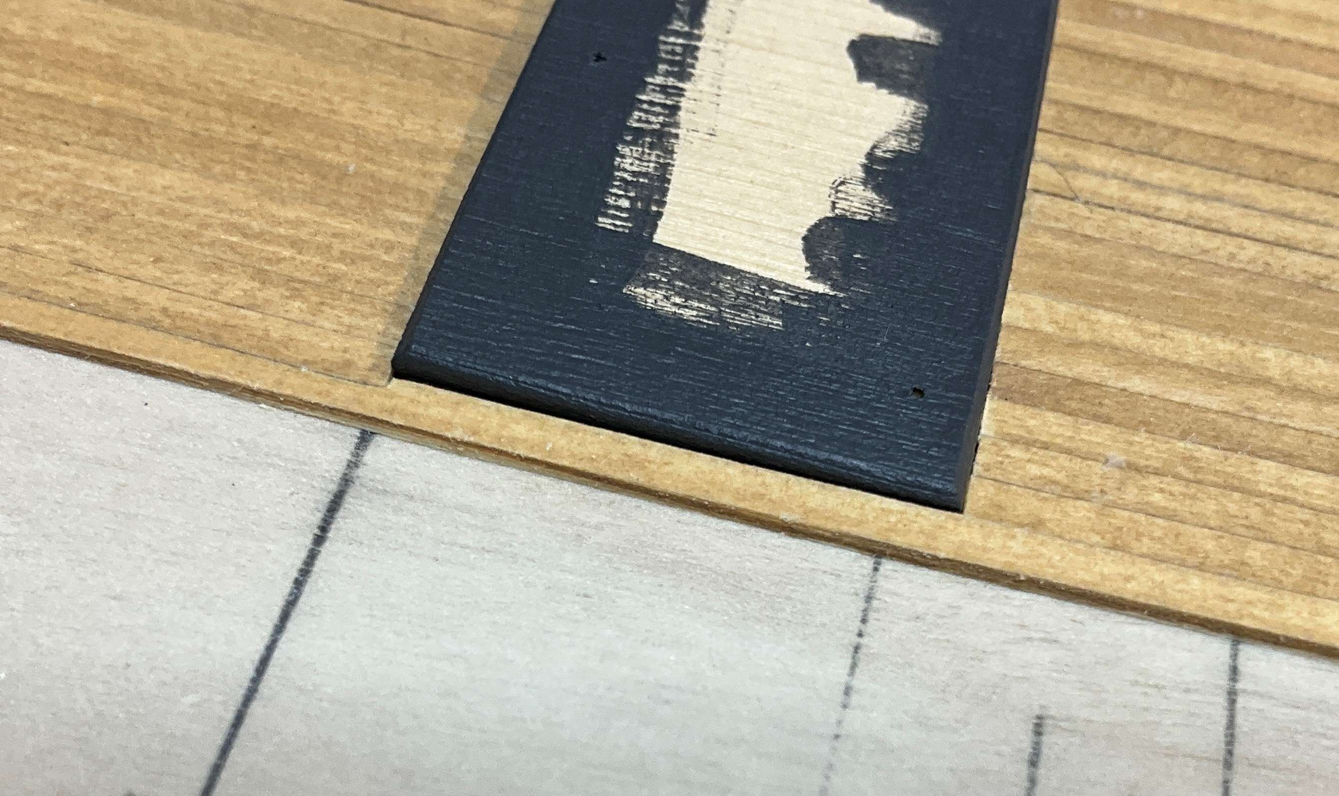
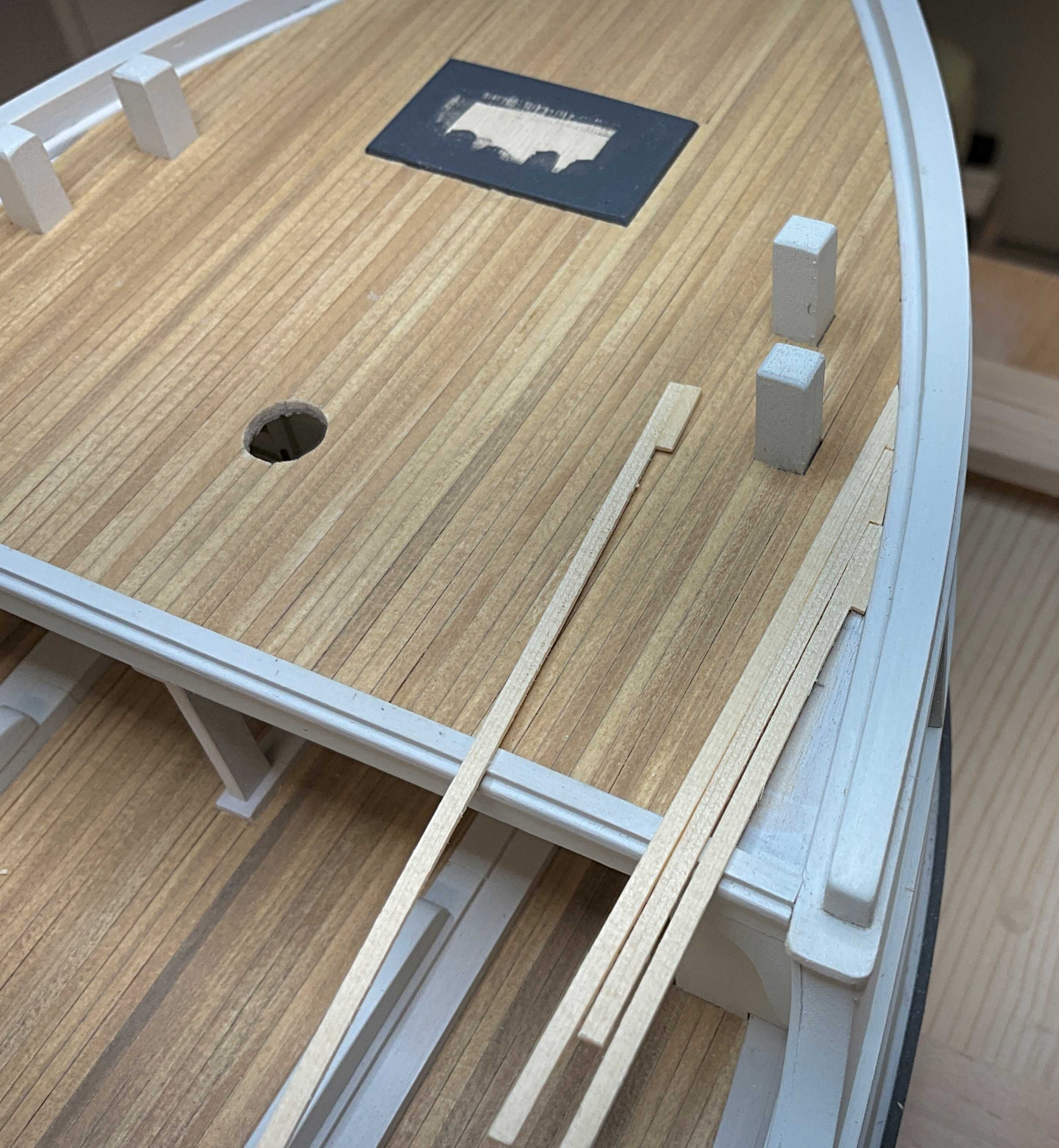
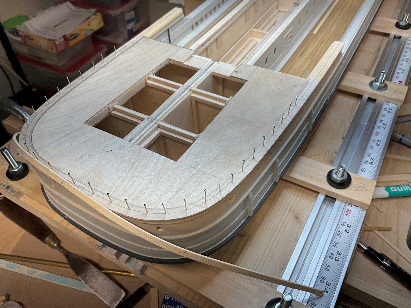
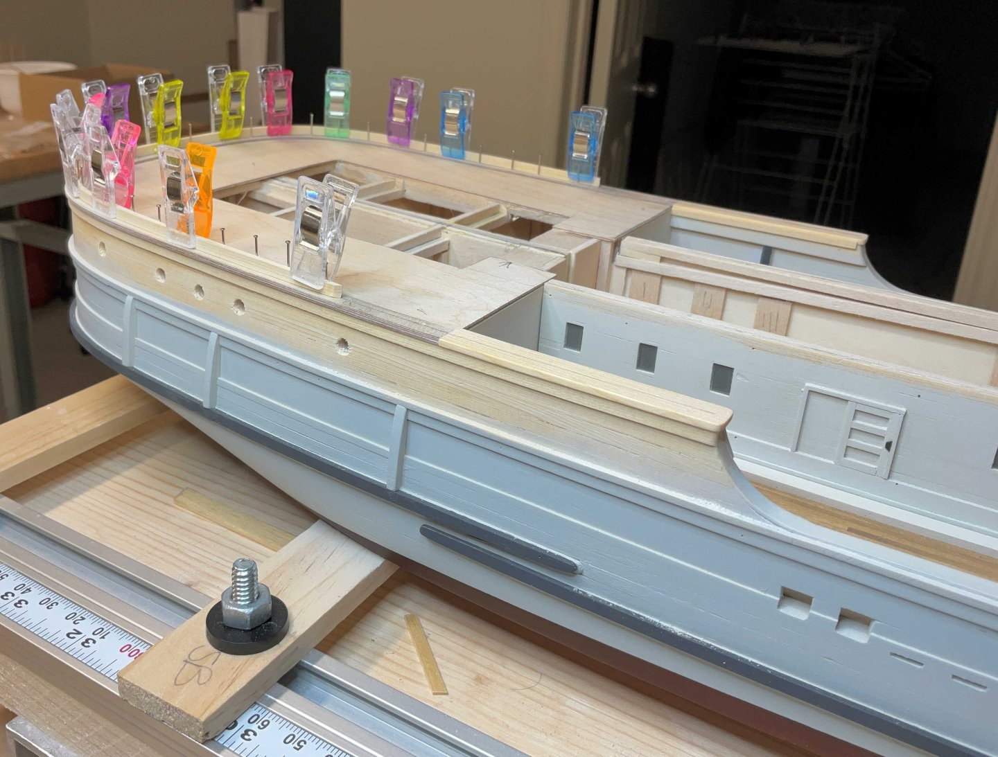
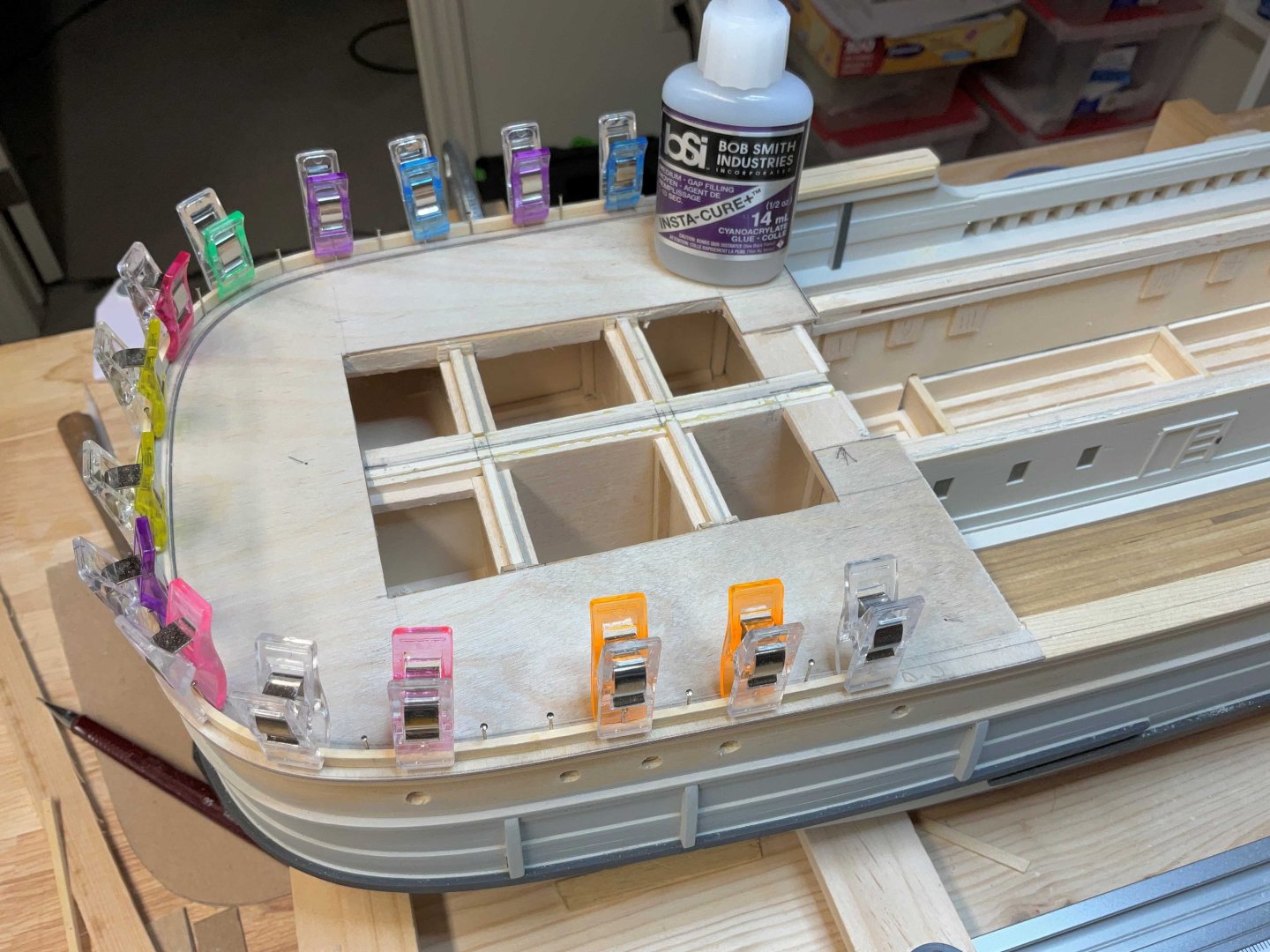
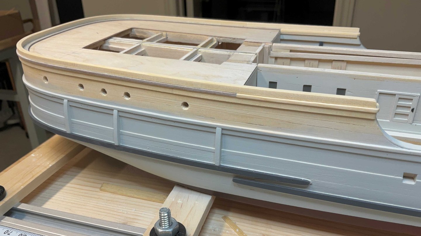
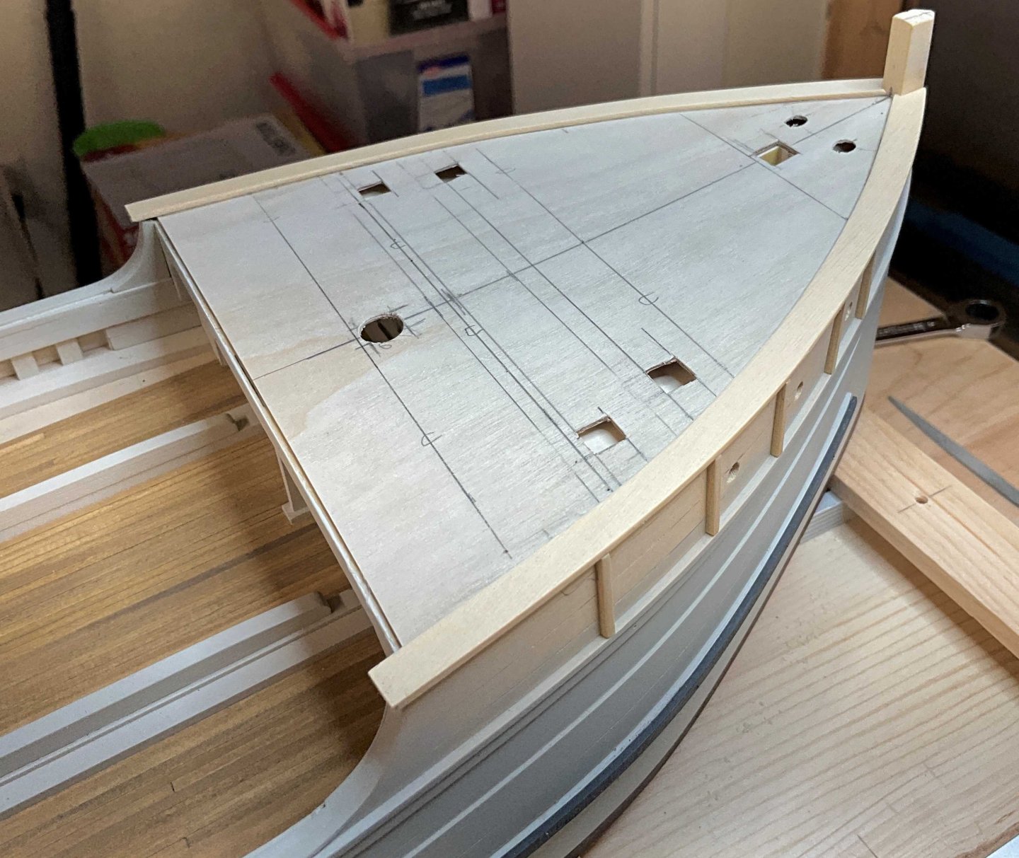
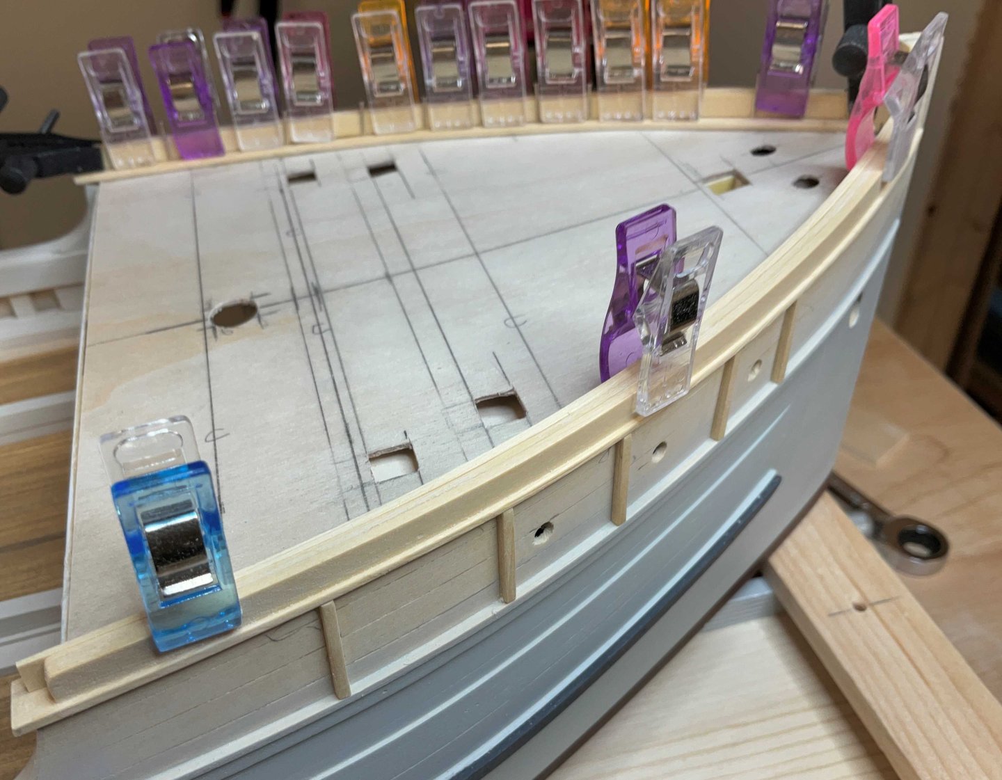
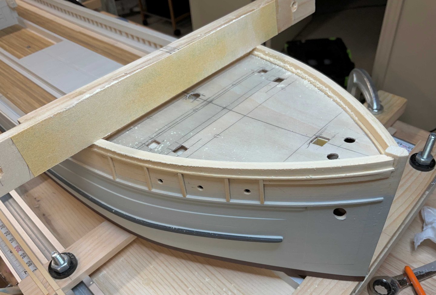
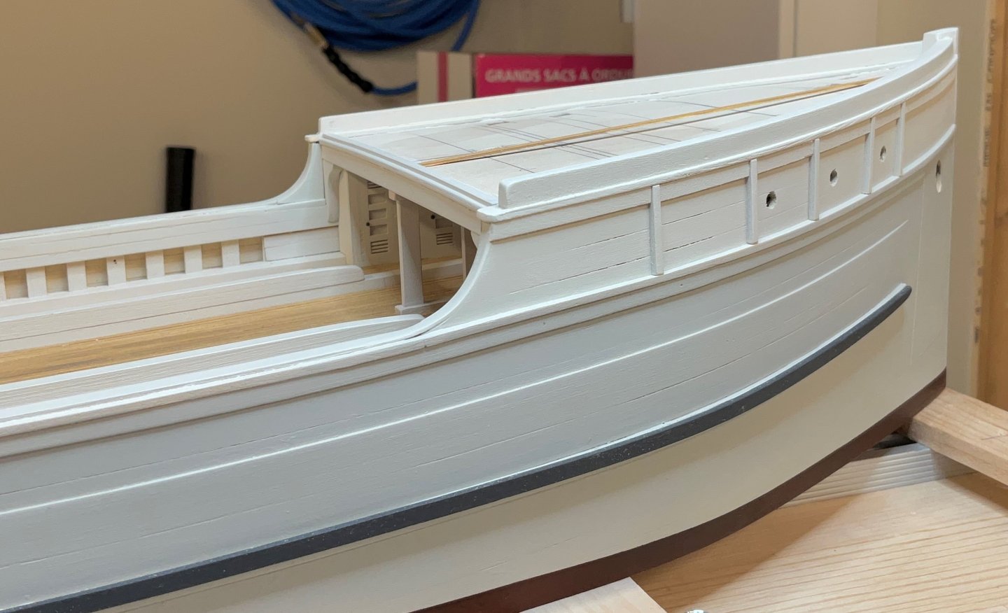
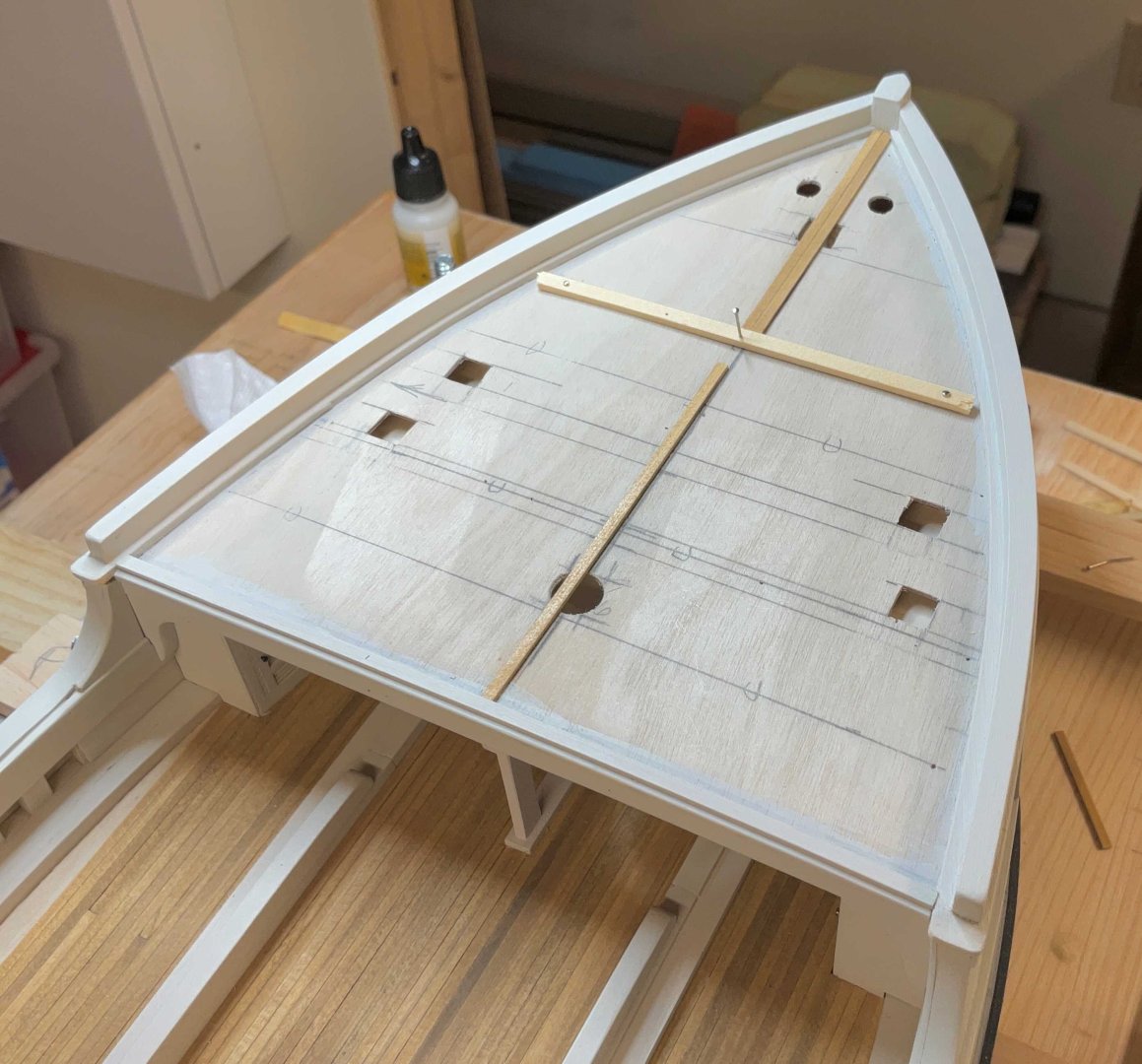
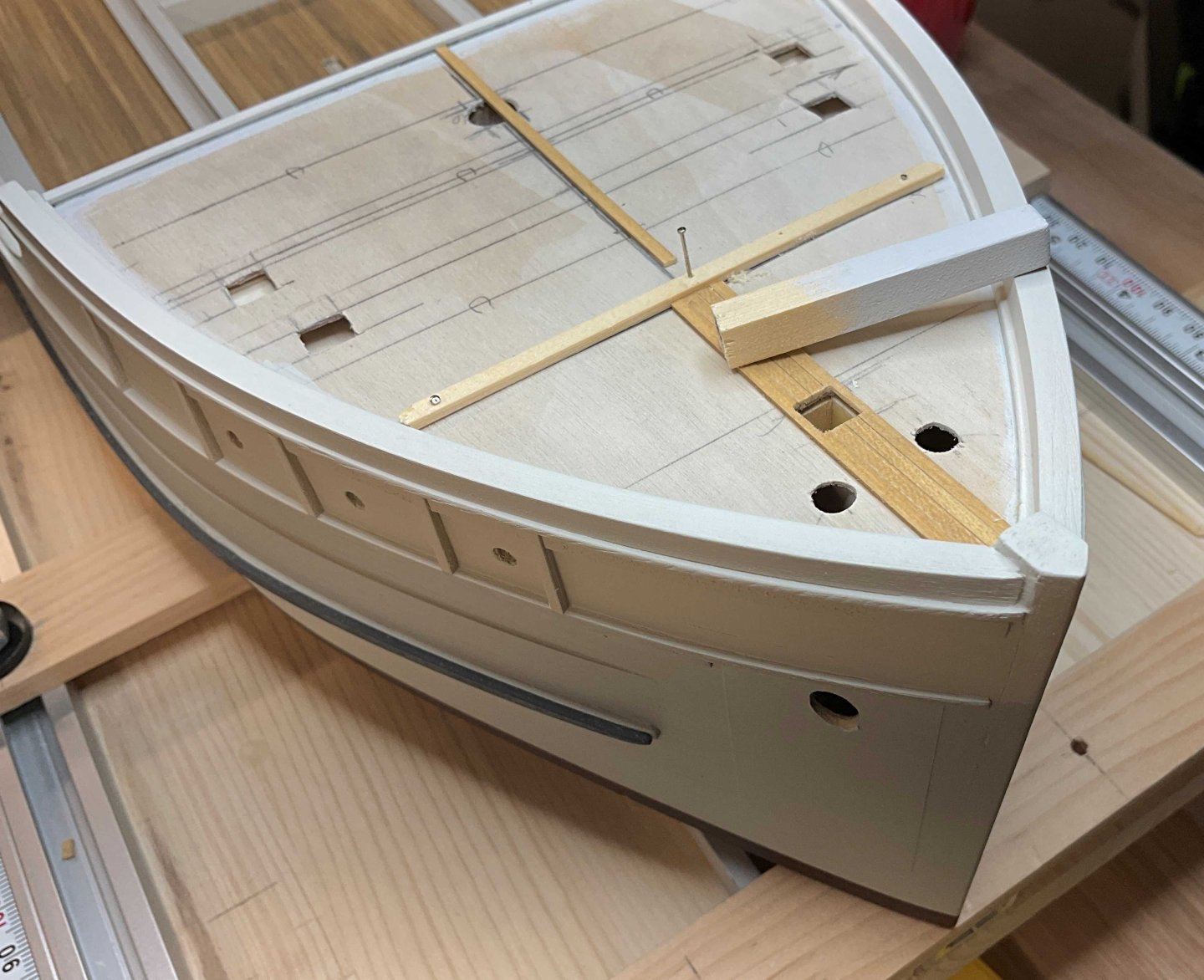
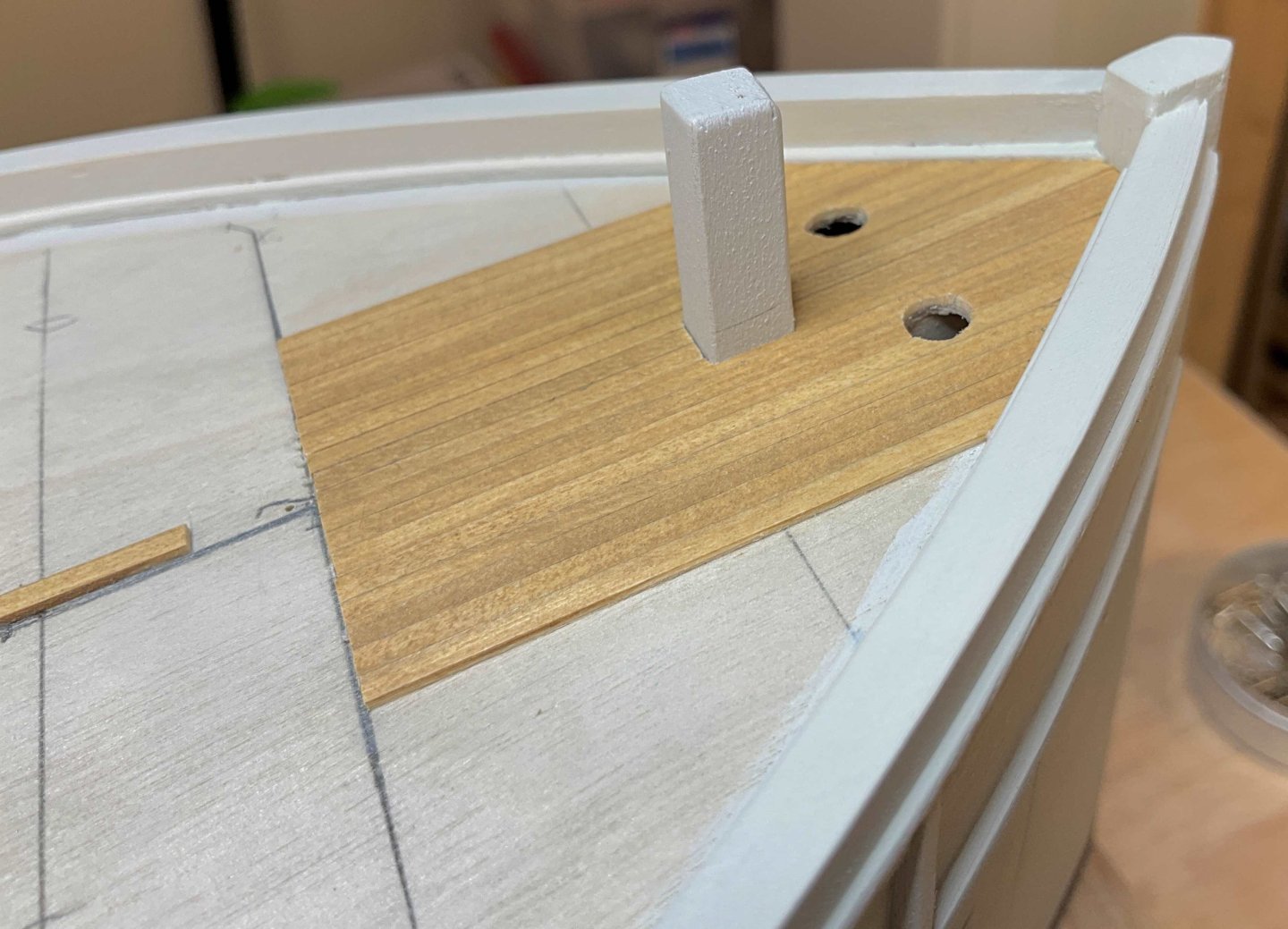
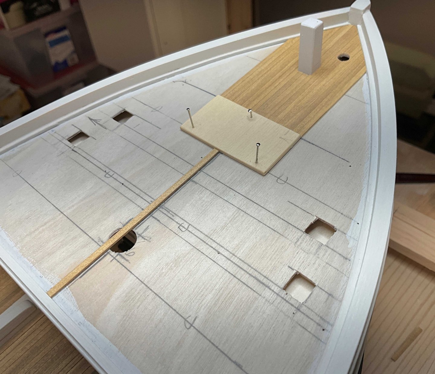
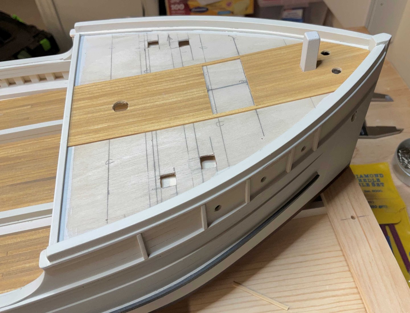
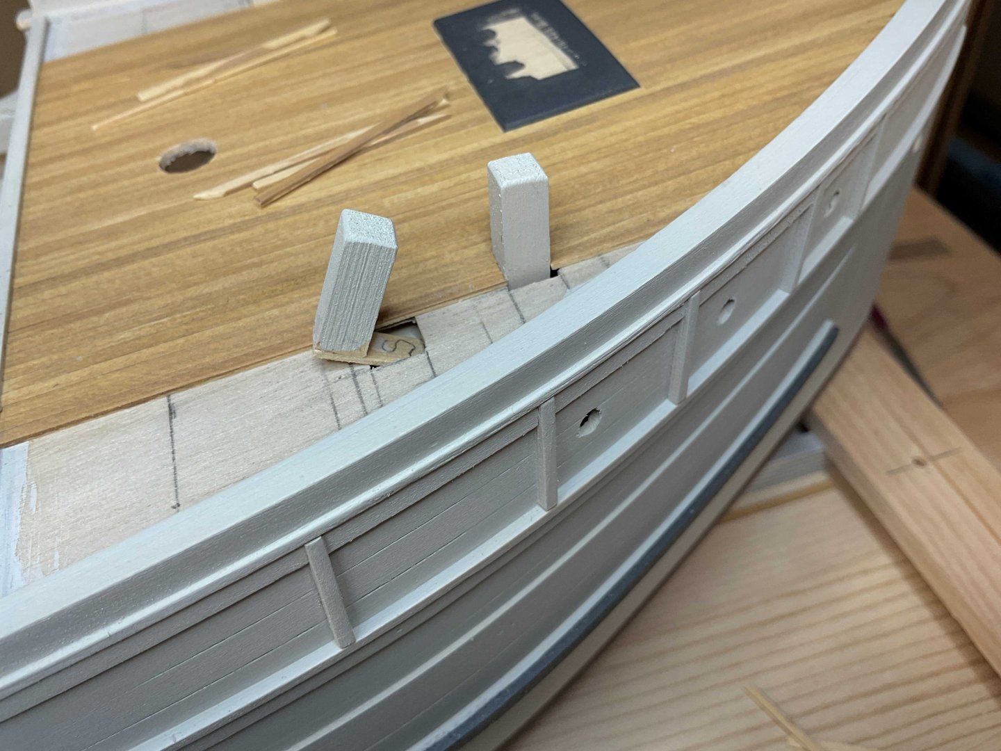
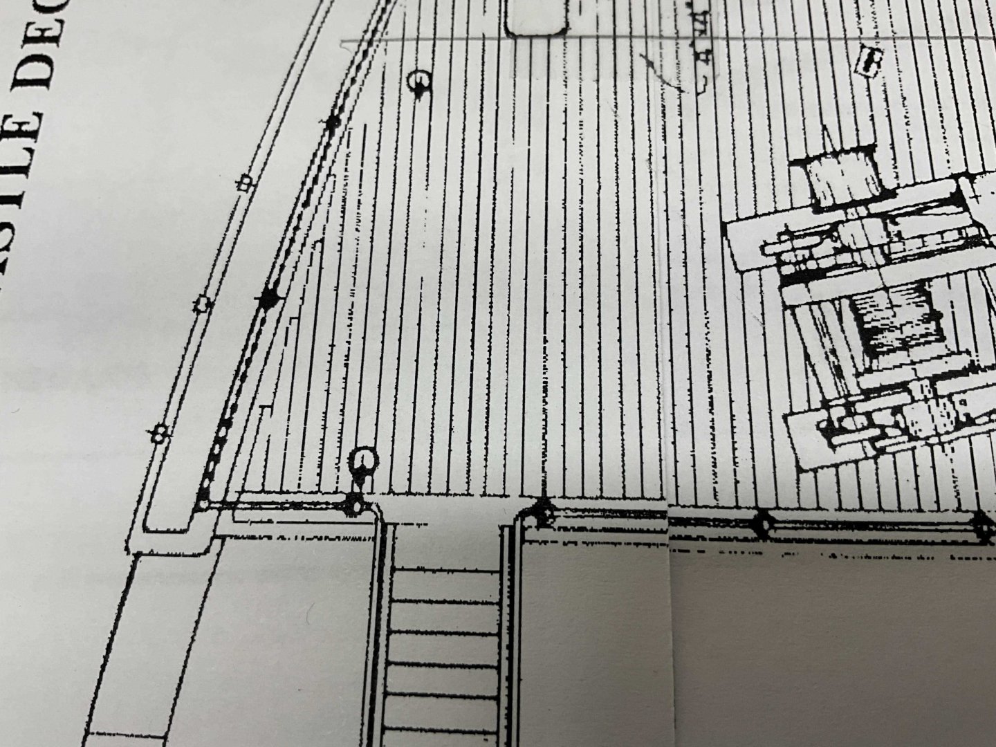
Hi Everyone, hope you are all doing fine. Thanks to all for the Comments and Likes! This update starts with the making of the waterways for the foc'sle deck. They were cut from a sheet of 1/16" AYC and sanded to shape. The coamings are made by layering three 1/16" x 3/16" strips. The waterways were scribed to show where the center plank is located and pins were placed to support it while it was attached with CA. The outer plank was glued to the center plank and the waterway with white PVA The inner planks were glued to the center planks and the waterways also with PVA. The thickness of the inner plank was tapered to 1/32" because the coaming gets narrower towards the aft end. I made a sanding stick long enough to span the deck and sanded the tops smooth The coaming across the aft edge of the deck was installed and after some sanding it went to the paint booth The deck planking was laid out to where it stops at the pad for the anchor winch. The 18" x 18" bitt slides into the hole that was left in the bulkhead former The planking from the winch pad aft and the forward planking didn't match in width so the next planks on either side of the pad needed a width adjustment. The smaller bitts port and starboard were the next obstacles. A small pad was glued to the bottom of these bitts to to help them sit vertically when they are glued to the horizontal bulkhead spacer just below the subdeck The last planks go and get all fancy. They will be covered in the next update Hope to see you then


-
Jacques, it’s nice the way that you’re refining your modifications on the fly. Fun to watch.
-
Siggi, congratulations on completing this beautiful ship. Your rigging is incredible!
-
Jacques, very interesting start to your new build. Thank you for including the Makerspace photos and experiences. The change of scale will make her feel right at home with the rest of your builds 👍
-
Hi Shawn, I was in a similar situation a while ago so I used a tower fan with a pleated furnace filter covering the intake. Depending on the size of the filter you can cut it into a few pieces. I used Velcro tape to hold it on. These fans are fairly cheap and very quiet.