


Saburo
-
Posts
27 -
Joined
-
Last visited
Content Type
Profiles
Forums
Gallery
Events
Posts posted by Saburo
-
-
Glad you are back and hopefully doing better Mic.
Bill- Keith Black, Mic_Nao and mtaylor
-
 2
2
-
 1
1
-
Following with interest and your neat workmanship is admirable Fred.
Bill
- FrankWouts and Ryland Craze
-
2
-
Beautiful!
Bill
- mtaylor and Knocklouder
-
2
-
Well that was a hoot. I thought it was related to travel/device issues. Sure glad it's back up and running.
Bill
-
Greetings to all of you here at Model Ship World. I am on a visit here in Southern California attending graduation ceremonies for grand children at present but, I will be back home in Florida in a few days to begin this log in earnest.
For now I'm going to open an introduction and take my place in line to build Syren Ship Models HMS Winchelsea.
Until about a year or two ago my interest in modeling has been aviation, building plastic/resin kit models. Then surfing around YouTube I ran into Olha Batchvarov, then Kevin Kenny, and finally Chuck Passaro. After lurking around MSW and enjoying all the wealth of learning and experience, (at all levels) I'm here. Oh yes, Did I mention the comradery?
Bill
- scrubbyj427, FrankWouts, ccoyle and 7 others
-
10
-
Again Jim, you're build is motivational/inspiring. I really should start my own build here and overcome my bashfulness. thanks' to you, Glenn, Rusty, John, Chuck and so many others in this forum.
Bill
- FrankWouts, Ryland Craze, James G and 1 other
-
3
-
1
-
-
-
Very interesting subject. I'm following you're build Mix. Am I correct in that the woods to be used are pear, box, ebony, and cherry?
- Mic_Nao, mtaylor and Keith Black
-
2
-
1
-
I have thoroughly enjoyed this journey Fred. Thank you for sharing this build with us and the inspiration it's given me.
Bill
-
You're build is motivational Jim. Thank you,
Bill
- FrankWouts and James G
-
1
-
1
-
On 11/21/2022 at 6:51 PM, Chuck said:
Continuing with the stem/keel assembly....
The remaining sections of keel were added working my way aft. The keel is actually two layers. I added one layer at a time. Each segment is numbered. The numbers face inward so when the two layers are glued up you cant see them.
Here is the entire keel all put together. Each segment remember is in two layers and I added them one layer at a time trying to get real nice and tight scarphs. Its not difficult when done in layers.
I also added the false keel. This is the thin strip on the bottom. This was done with 1/8" wide strips the same depth as the keel. I simulated the seams with a pencil. There is still no finish on these parts so it will really look great once I add some wipe on poly.
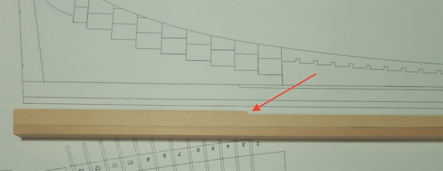
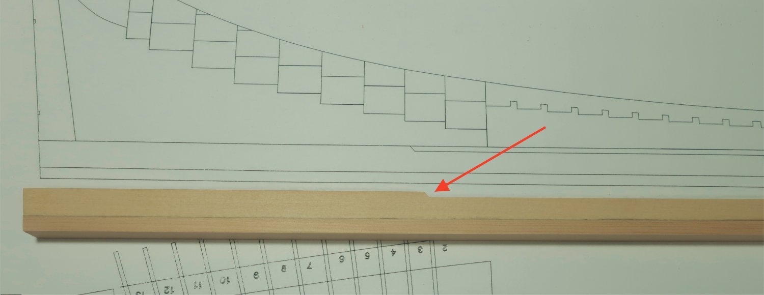
On the aft section you will see a small step where the rabbet strip will end. You will probably need to adjust where this is. I made the parts so this was a bit forward of where it should be. Just lay the keel assembly as it stands on top of the plan and mark the exact location for this slanted step. Then use a sharp chisel or #11 blade to cut this step in the exact location.
Also note that the false keel may seem a bit wide top to bottom. I have done this intentionally. It is about 1/32" larger than needed. I have found that the false keel when made of cedar will take a beating throughout the project. It will get dented etc. Even if you tape it to protect it. So I made it slightly taller so I can sand the bottom of the keel down smooth much later in the project. Just to smooth out any creases and dents.
The Rabbet...
The rabbet is done as I typically do on all of my projects. I realize the rabbet is a complex organism of sorts. It should have a "V" shape with and ever changing profile depending on how the hull planking enters it. I usually make a mess of that if carved with a chisel. Those of you who have the Speedwell books from Seawatch can see how Greg did this. He is much more handy with a chisel than I am.
So this will be simplified and should you choose to add the garboard hull plank will mostly be covered anyway. Using a simple strip here is neat and clean.
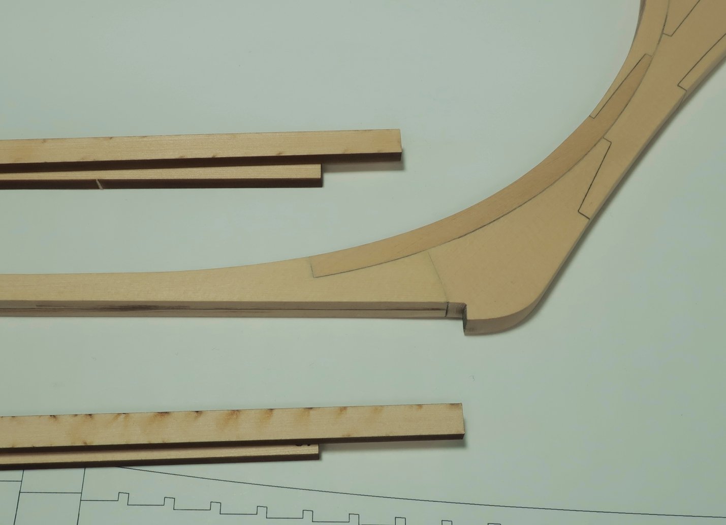
The one thing I have done differently this time is I laser cut the curved sections at the bow in two lengths. See the photo below. The two lengths are already glued on the stem assembly but I also show some extras on the table for clarity. They are 1/16" thick. The longer segment goes on first and is centered port to starboard. This will leave a nice lip on both sides. Then the shorter laser cut rabbet strip is added. No need to sand the laser char off these.
The remaining rabbet strip that works itself aft is just made using a 7/32" x 1/16" cedar strip. It ends at that slanted step you so carefully chiseled just a moment ago.
The Upper and Lower Aprons...
Now these pieces you have no doubt seen being made on many POF model. The upper apron is nothing special. Its a plain segment that is 3/8" thick. Simple enough. The LOWER apron is a different story all together. It is much more complex. You have probably seen folks hand chiseling tiny steps into both sides of the lower apron...once again take a look at Volume one of the Speedwell books.
I wanted to simplify this however. Not because it could be difficult to do but because I know that most folks dont have vertical mill, or disc sanders or all the gadgets you often see when folks make the lower apron.
I have decided to make the lower apron using many separate parts instead. Looking ahead to adding the forward cant frames, each set of cant frames has a different angle sanded into the heel of it. This is so it can be "canted" forward. This is simply not going to work to easily if you dont have a disc sander. So I created small wedges with the angles already pre-set on them to accept straight right angled heels on the cant frames.
I hope that makes sense.
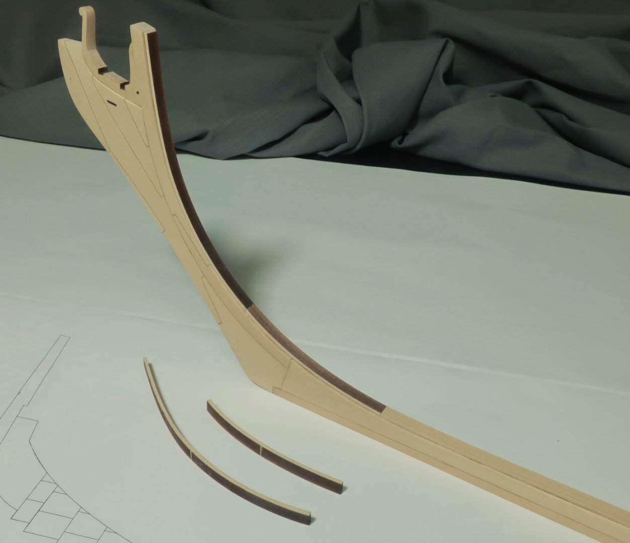
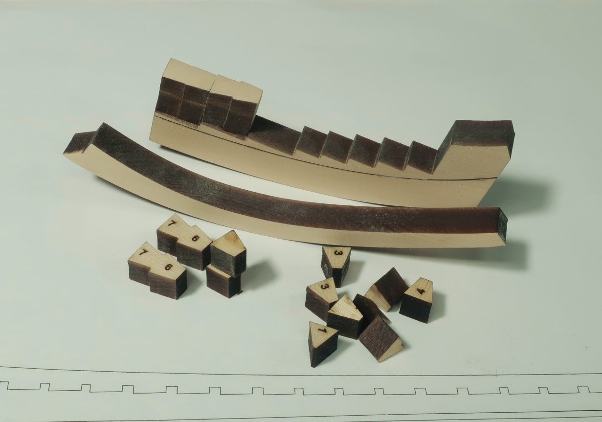
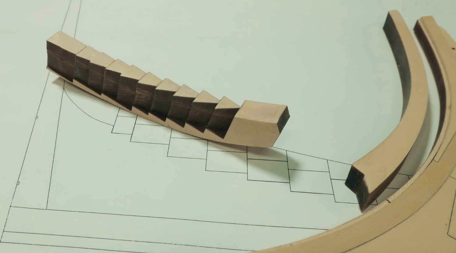
See below. The upper apron is in front...easy peasy. Set that one aside for now. The lower apron is laser cut with a series of steps. On these steps we will glue the pre-angled wedges. But using this approach leaves the bottom of the lower apron very thin even at this scale. It can easily break or get misshapen. So I have laser cut the "stepped" lower apron attached to a sacrificial piece of wood. You can use it as a handle. DO NOT remove the lower apron from this "handle" until all of the little angled wedges are glued to it. Those will give it enough strength...a remarkable amount of strength actually. In the photo below I have already added two of the laser cut wedges which show the angles for the cant frames. Check your plans as these are prominently shown. Work from the aft side forward.
Each angled wedge is made on two layers. They have laser etched numbers on them and correspond to the plan. Gle the two layers together with the numbers facing each other. This is important. Glue the two halves together "number facing number". The next to be done for me are the parts marked "7 & 6" in that photo. I will glue them together now.
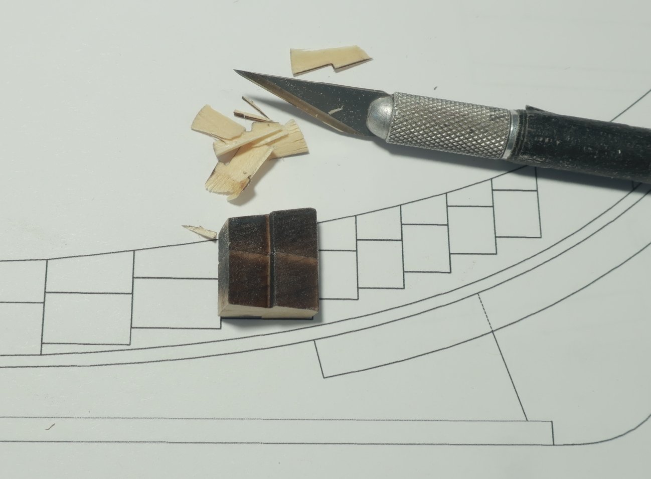
Once glued together with the numbers facing each other, you could make life easier for yourself later by cutting them down a bit. Once the two pieces are glued together they are too tall. This doesnt matter at all but if you trim them to match the plans it will be so much easier to fair the inside of the hull when the time comes. The Keelson will fit so much nicer on top of this when the time comes. Below you can see me doing just that. With a sharp blade I am trimming the top to match the plans. Make sure you have the piece facing the correct way. Place it on the plan and draw a line where the top portion can be shaved away. Do this for every piece...I know its a pain. But you will thank me when it comes time to add the cant frames later.
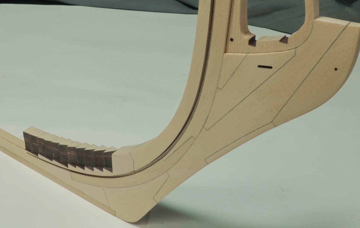
When all of the segments are glued onto each step of the lower apron base, you can finally cut away the bottom handle. It was held on by just a few connectors which are easily cut with a sharp blade. Hopefully you glued those wedges onto each step securely and didnt skimp on the glue. Glue each onto its step and also to the wedge proceeding it. Nice and secure. Center them down the top of each step. Dont mix up the numbers either. That would be bad because the angles match each individual cant frame. I also sanded the top of all those wedges so it looks nice and neat. It also matched the shape for the lower apron shown on the plans.

Note that you should not remove any of the laser char on the angled sides of these wedges. Not only would that screw up the angles laser cut into each of them, but it would also reduce their size. That should be avoided.
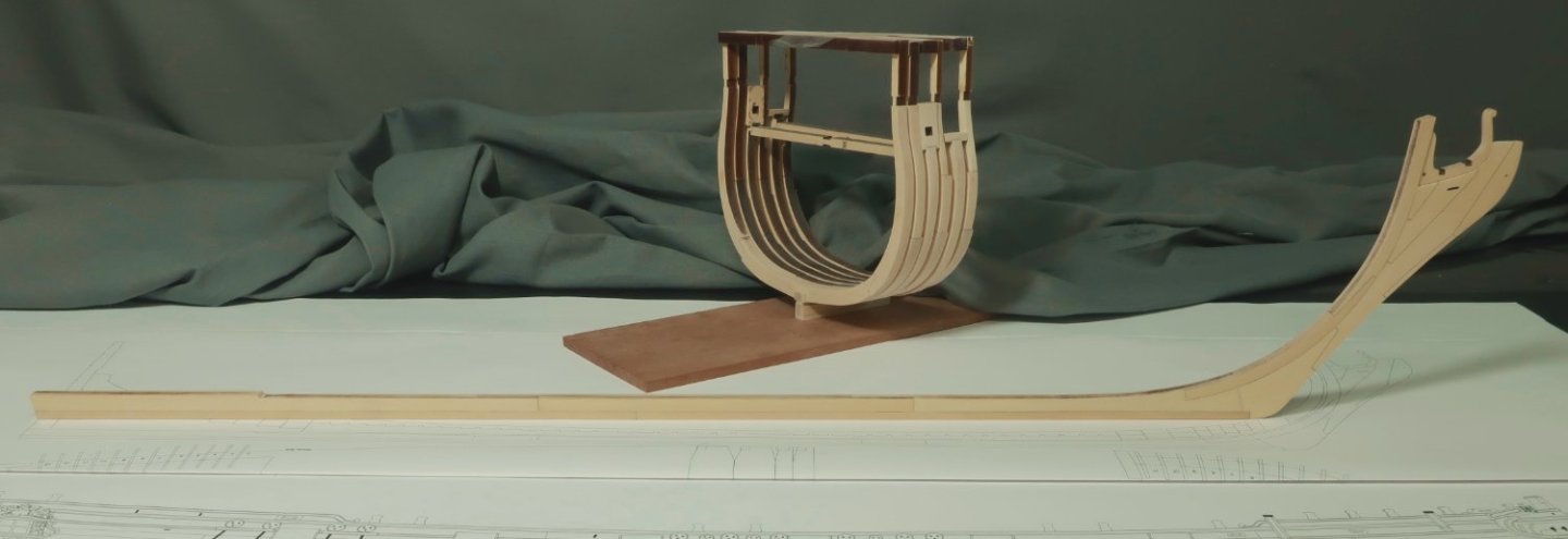
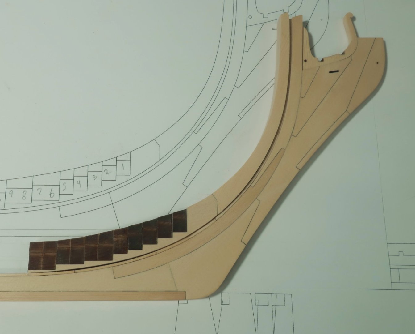
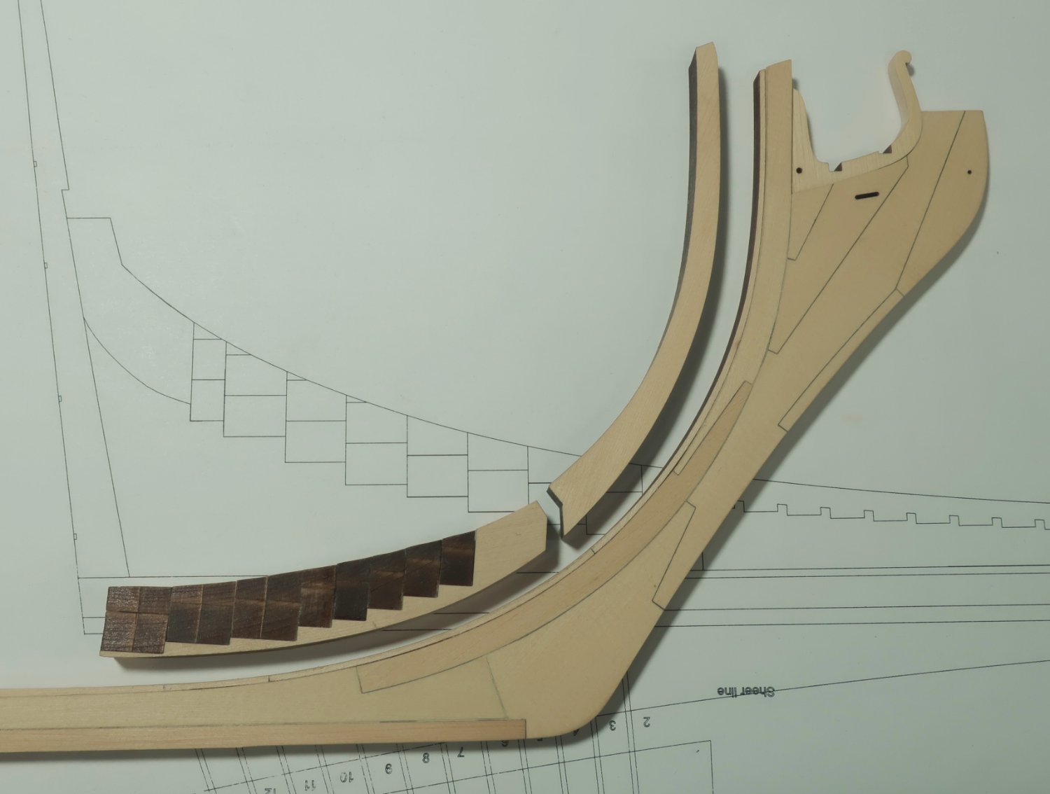
A dry test fit of the upper and lower aprons on the keel assembly below. trying my best to match the curve. Use the plan to find the exact location for the aft edge of the lower apron along the keel. You dont want it too forward or even too aft. Place the keel assembly on the plan and mark where the exact locations are for the upper and lower aprons. Note how the upper apron extends above the rabbet strip.
Note how the aprons are wider than the keel. The aprons should be centered on the rabbet strip leaving a nice over hang on both sides.

Still no finish applied to these parts yet. I will do that once the entire keel/stem assembly is completed. Thats it for today!!!
Any questions?
Way cool.
-
Welcome ChuckP. You're already off to a great start.
Bill
- mtaylor and Keith Black
-
2
-
Looking forward to seeing what you make of this build project Richard. My copy of the Ancre's Le Gros Ventre is on the way.
Bill
-
I'm looking forward to this Chuck. As a coincidence, I received my two volumes of Speedwell just this month.
Again, thank you for you're dedication and contributions.
Bill
- FrankWouts and mtaylor
-
2
-
-
-
On 10/18/2020 at 9:33 AM, glbarlow said:
Once again I agree. I always try to thank everyone who comments on my log because I appreciate the time they took to do it.. That’s best done by the quote selection option Chuck and I just used because that creates a notification back to the poster that he has a reply. It’s all about being active and having conversations, not a request line.
I'm learning alot here, and I can relate to this "newbie" topic. Besides being a Neanderthal in computer literacy, I don't have a clue how these forum sites work let alone the terms and nomenclature being passed around. I just want to say thank you to you Glenn, and to others like Chuck and John H. who after my clumsy efforts to communicate haven't got me cancelled yet. Again, I'm learning and I love this community.
Bill
- Peanut6, hollowneck, Obormotov and 2 others
-
5
-
Being new to this whole subject, forum, medium, and hobby in general I am in awe of it all and the talent displayed. I am inspired I suppose as I've already purchased and started playing with my Byrnes saw, not to mention Chuck's Cheerful products, membership with the NRG (No. 8120), and perusing the Washington plans purchased from the Guild.
Your build here Glenn is adding more fuel to the fire.
Thanks to All,
Bill
- Ryland Craze, BobG, glbarlow and 1 other
-
4


LˇAmarante by marsalv - 1:36 - POF
in - Build logs for subjects built 1501 - 1750
Posted
Wonderful, another great project to follow, enjoy, and learn from. Thank you Marsalv.
Bill