
moreplovac
-
Posts
794 -
Joined
-
Last visited
Content Type
Profiles
Forums
Gallery
Events
Everything posted by moreplovac
-
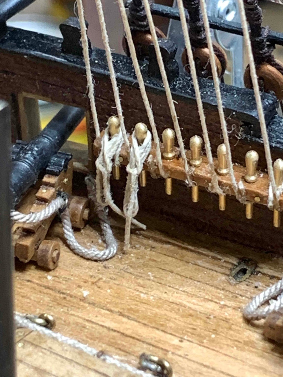
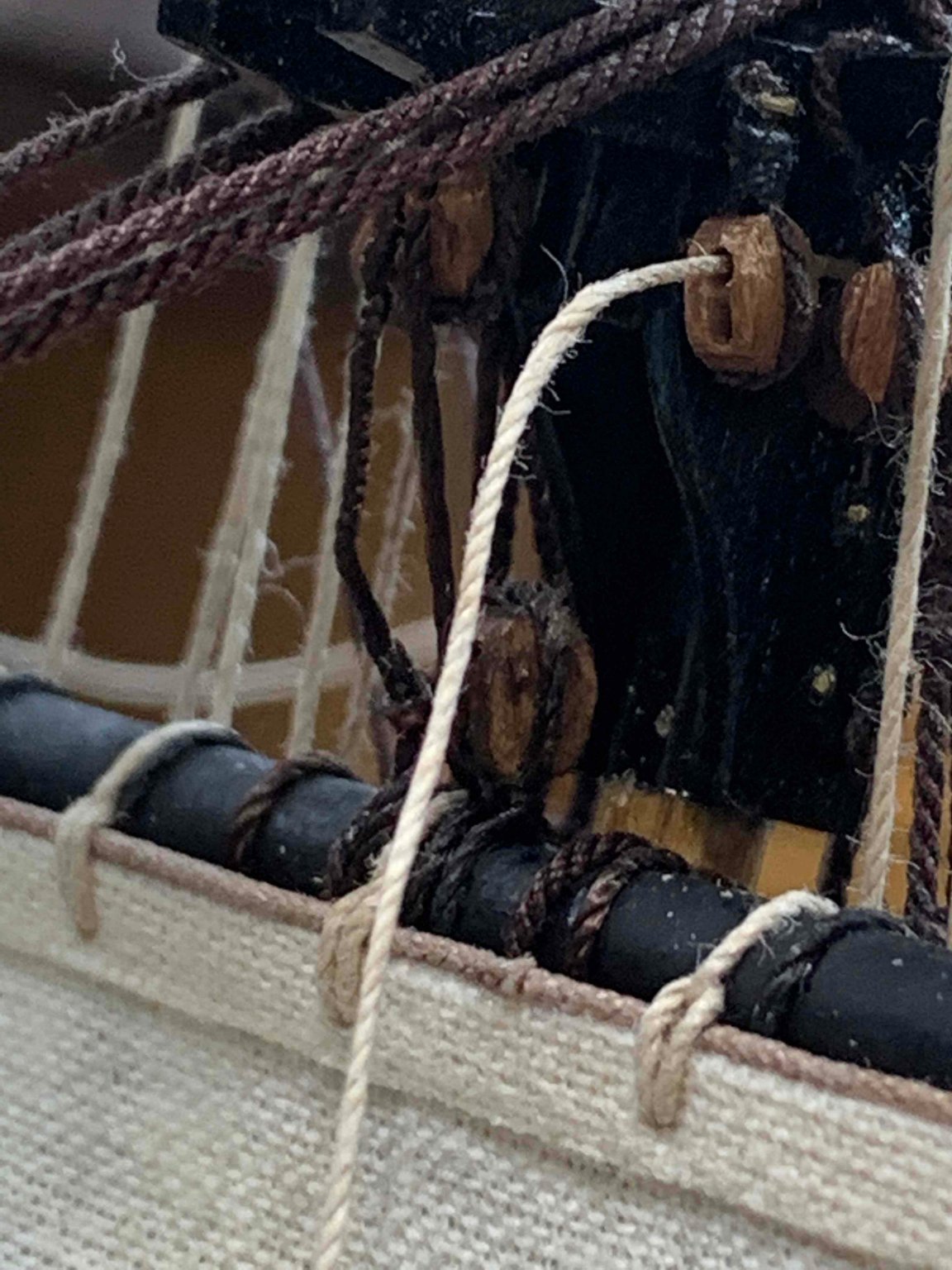
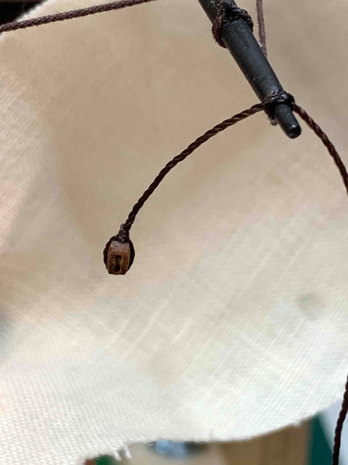
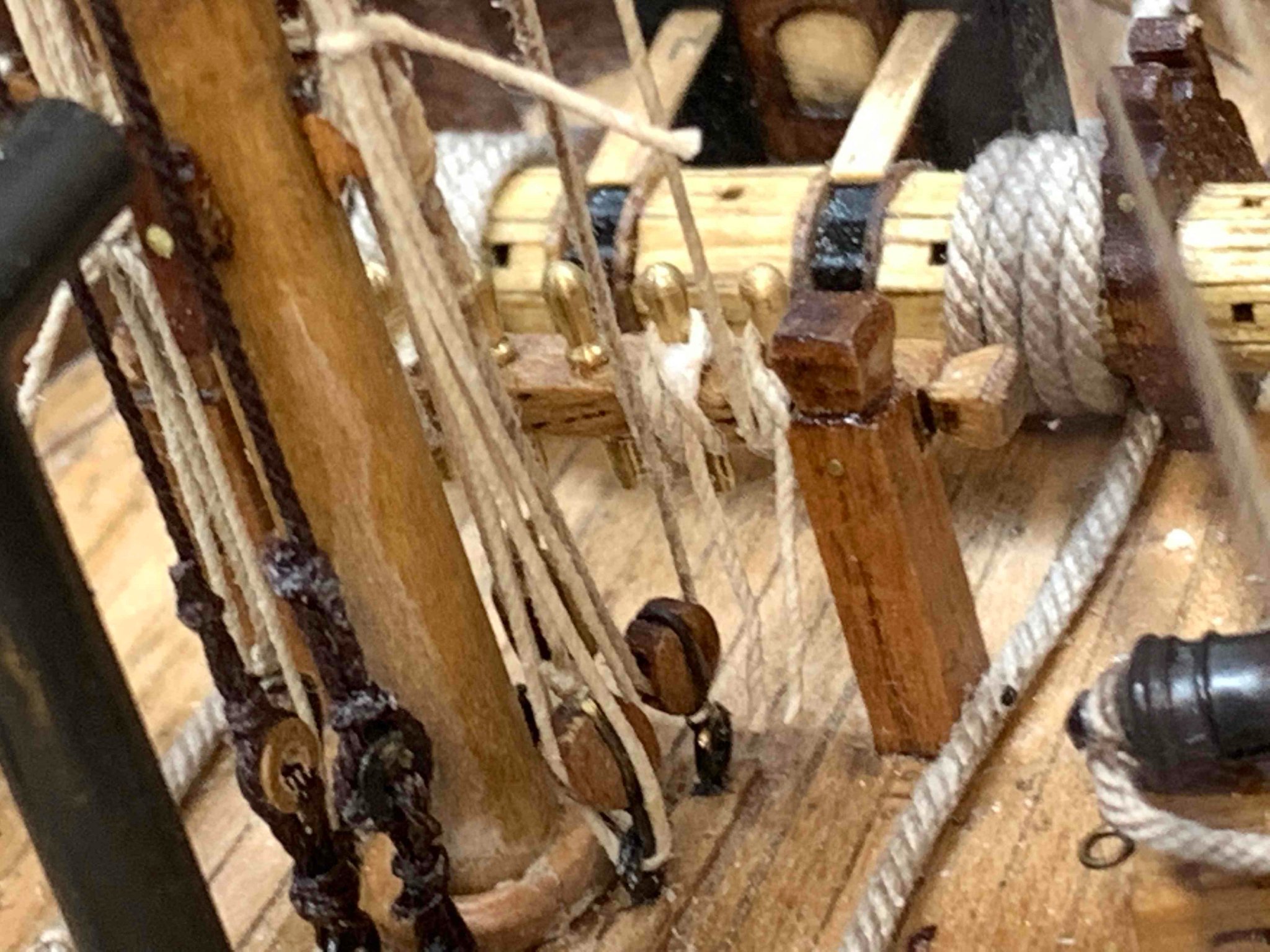
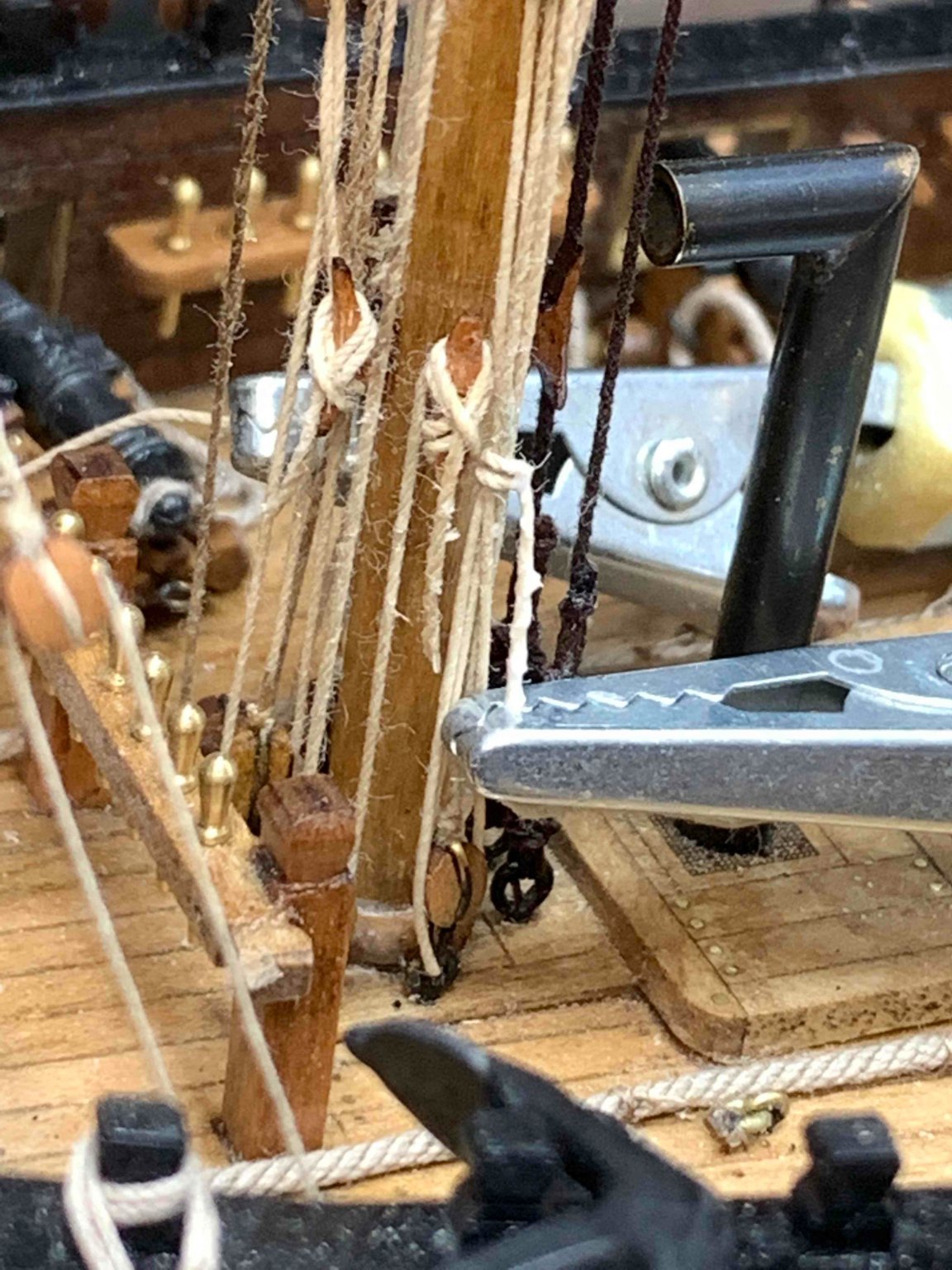
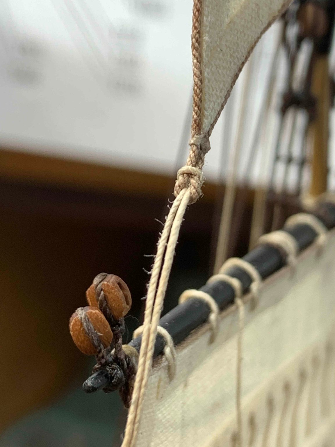
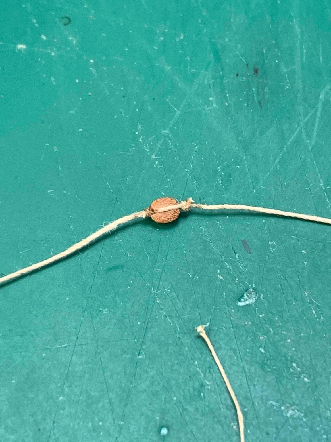
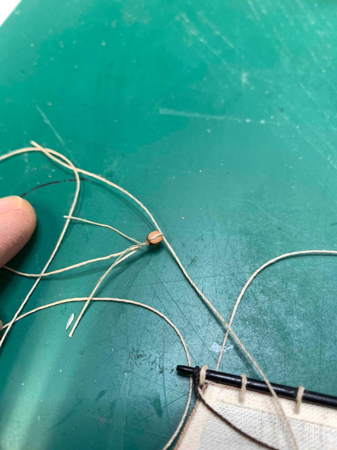
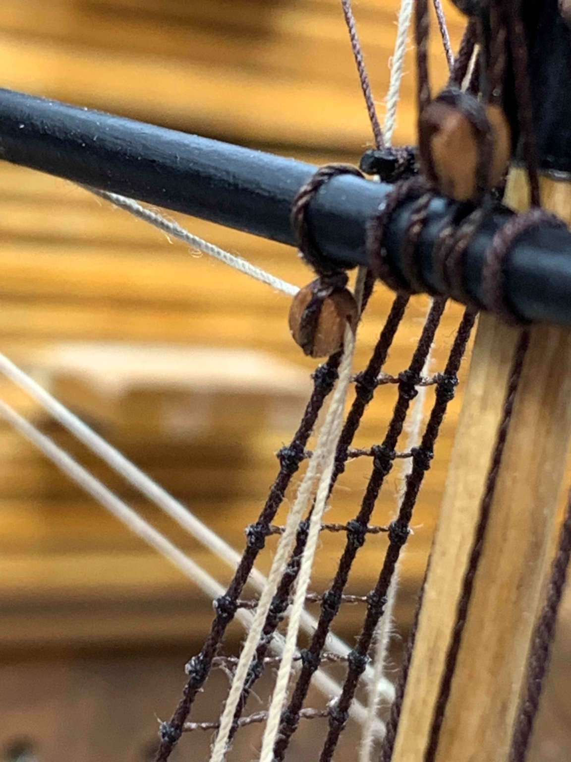
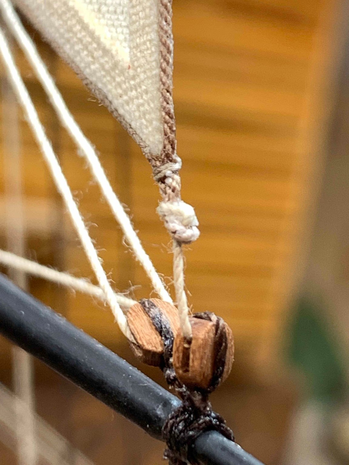
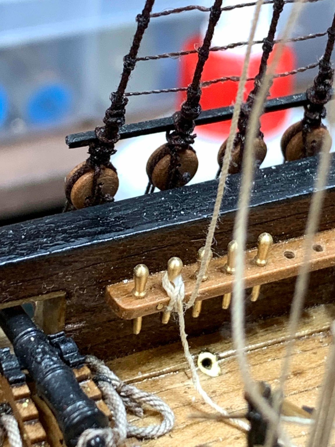
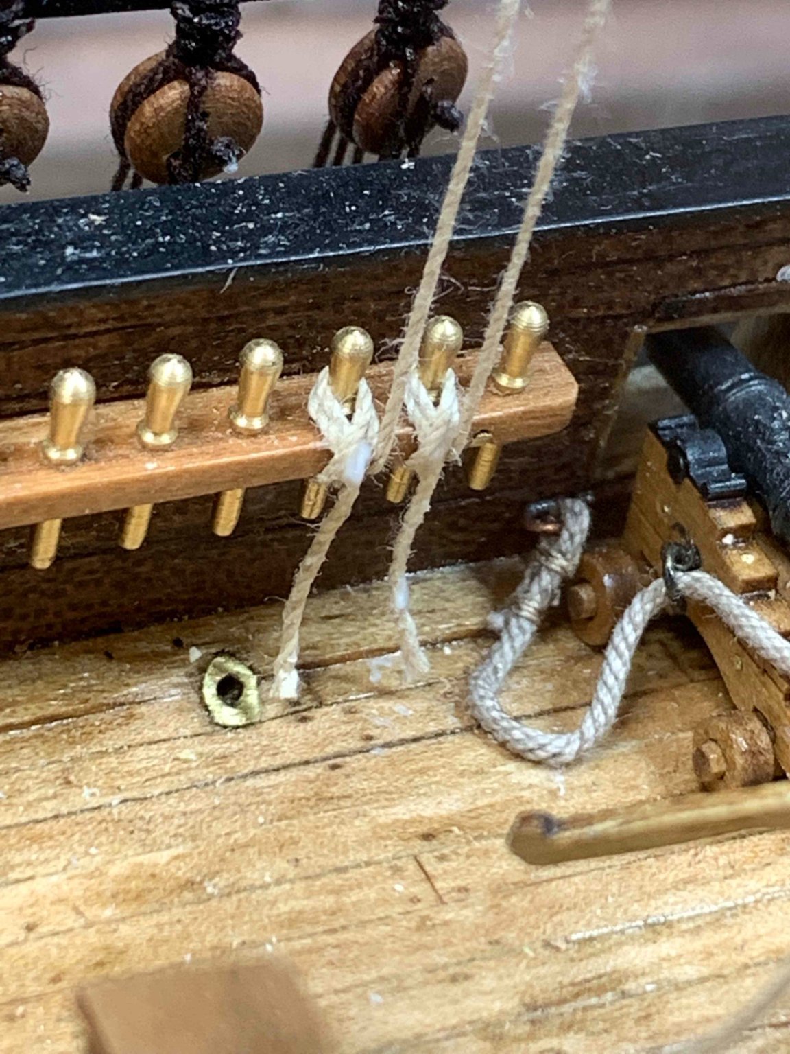
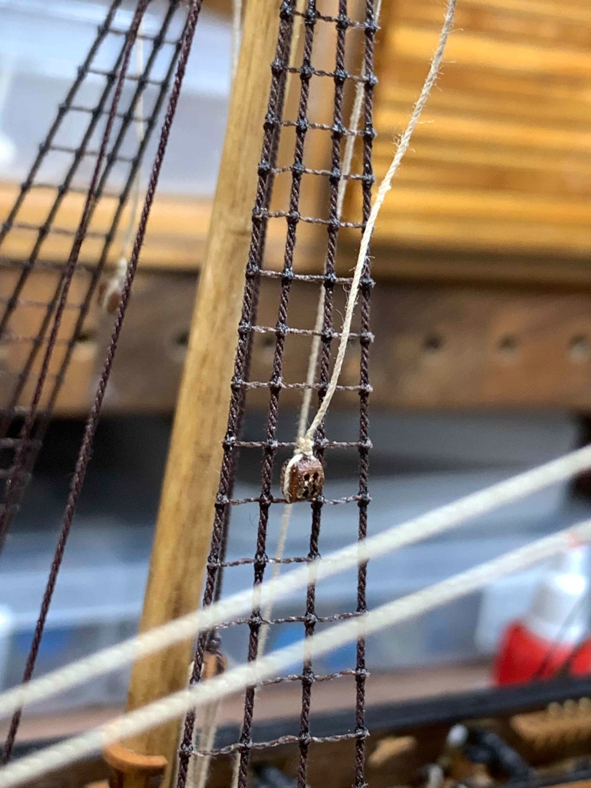
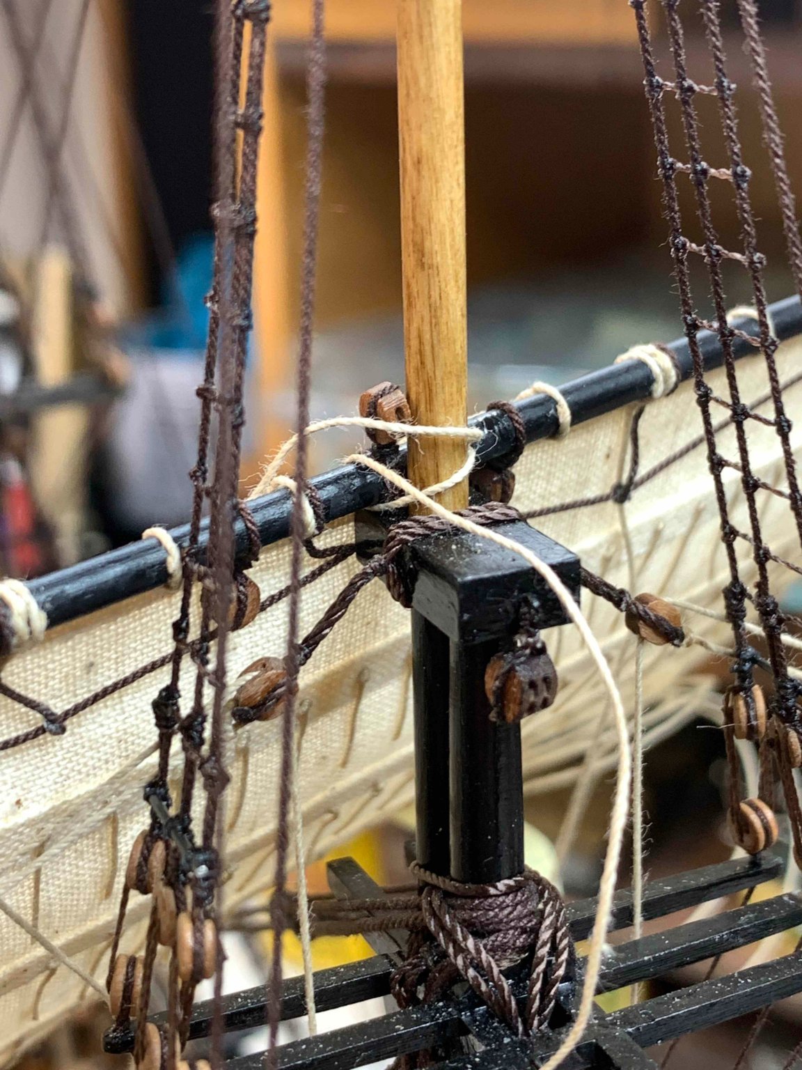
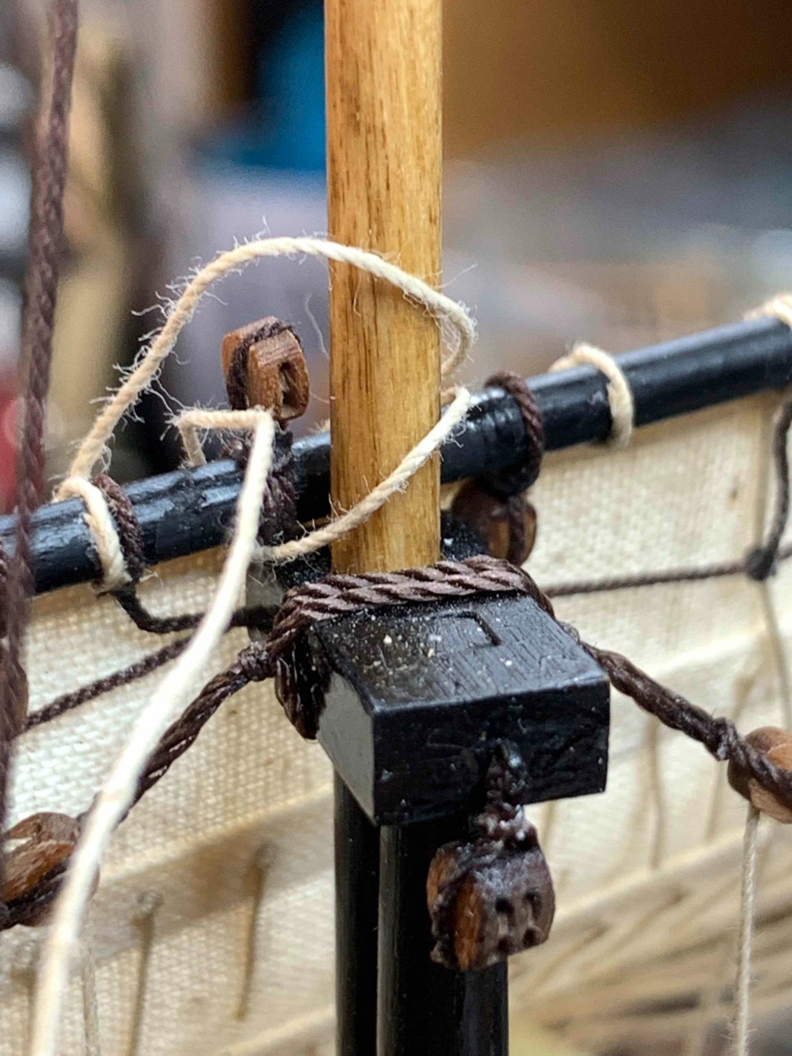
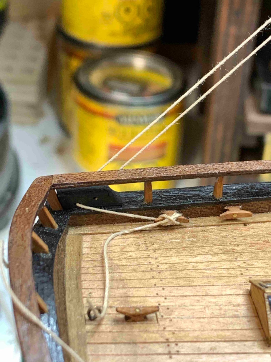
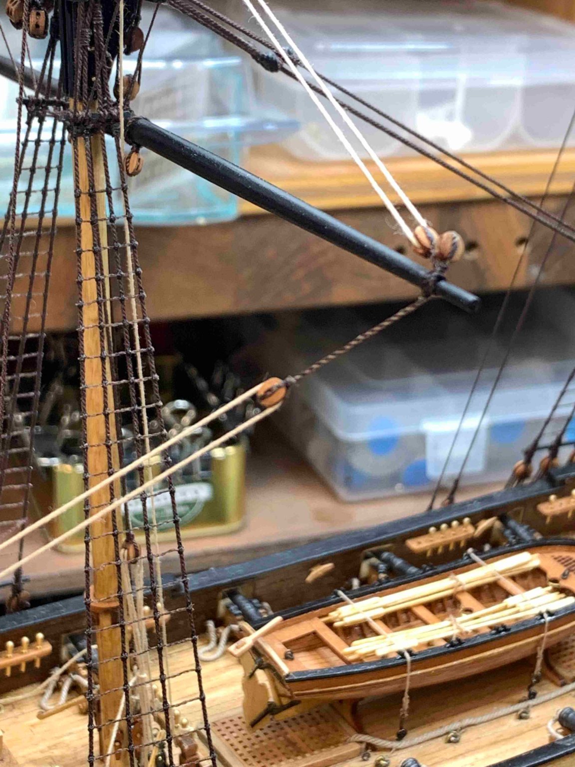
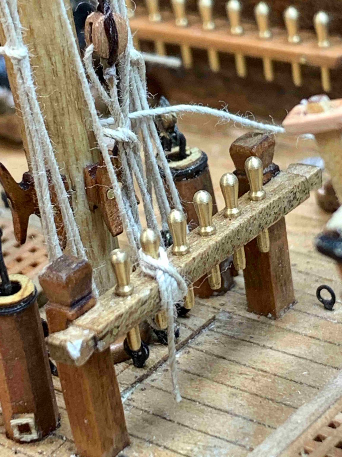
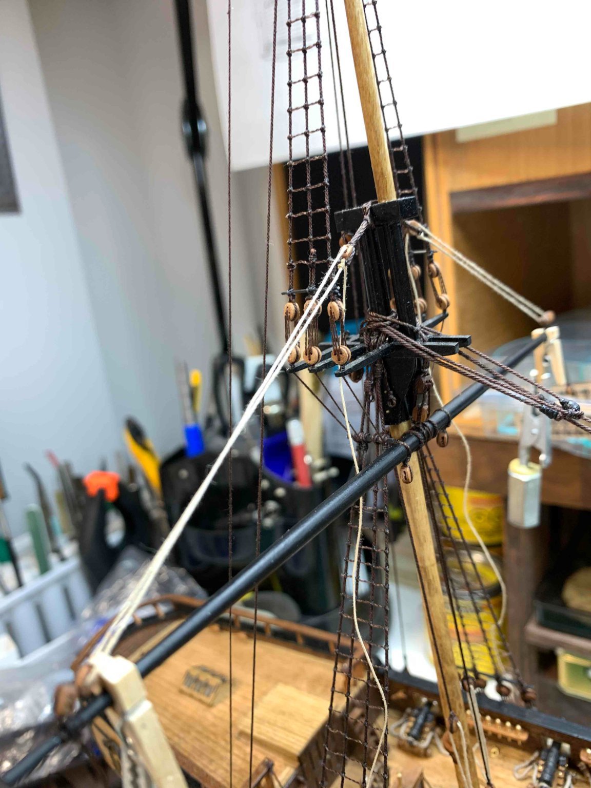
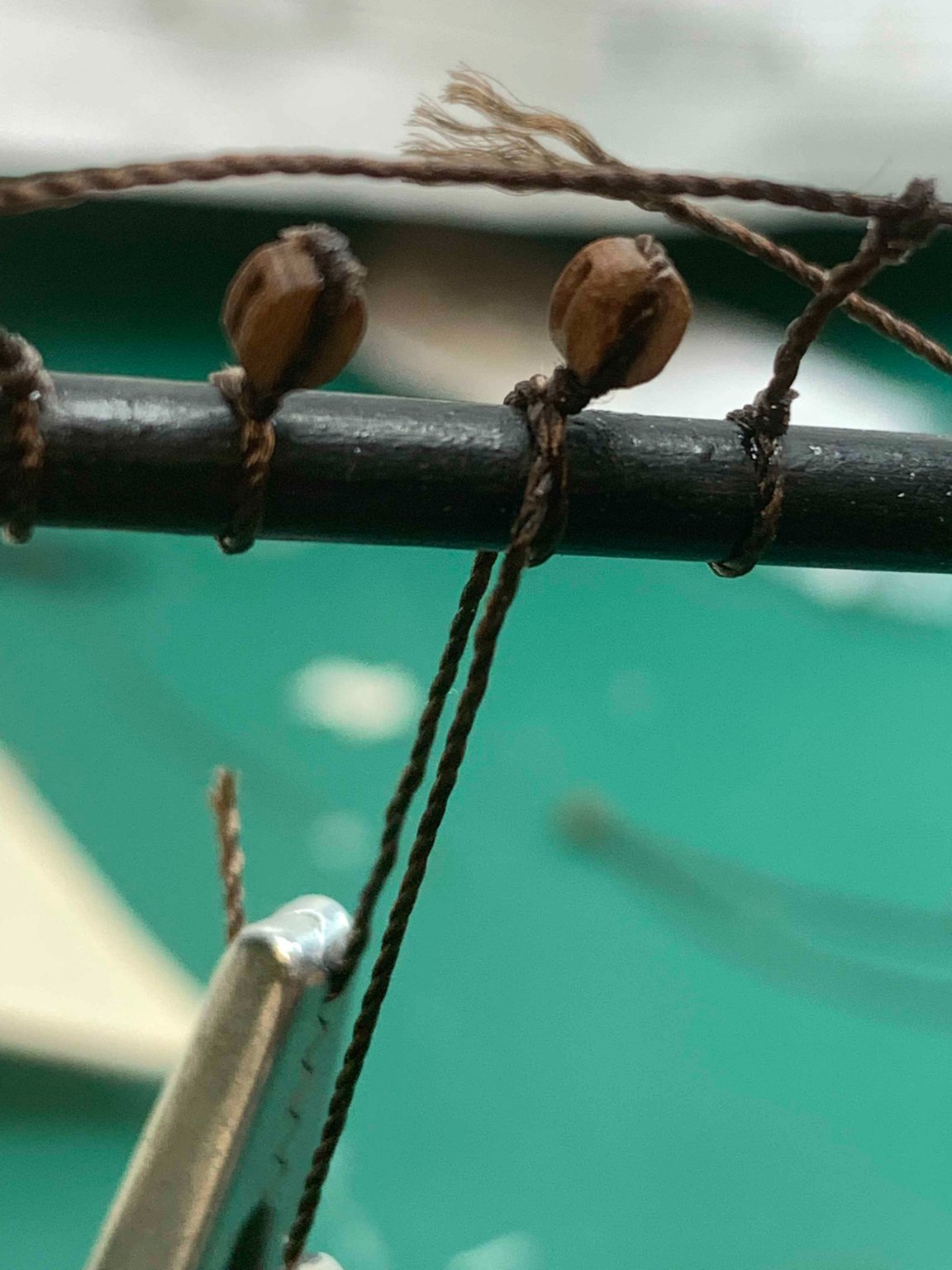
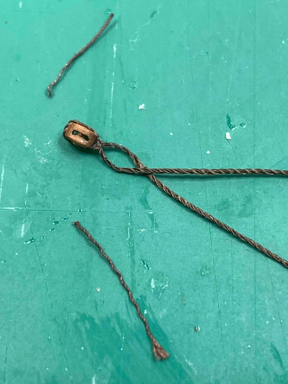
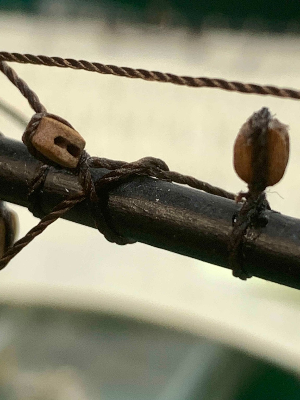
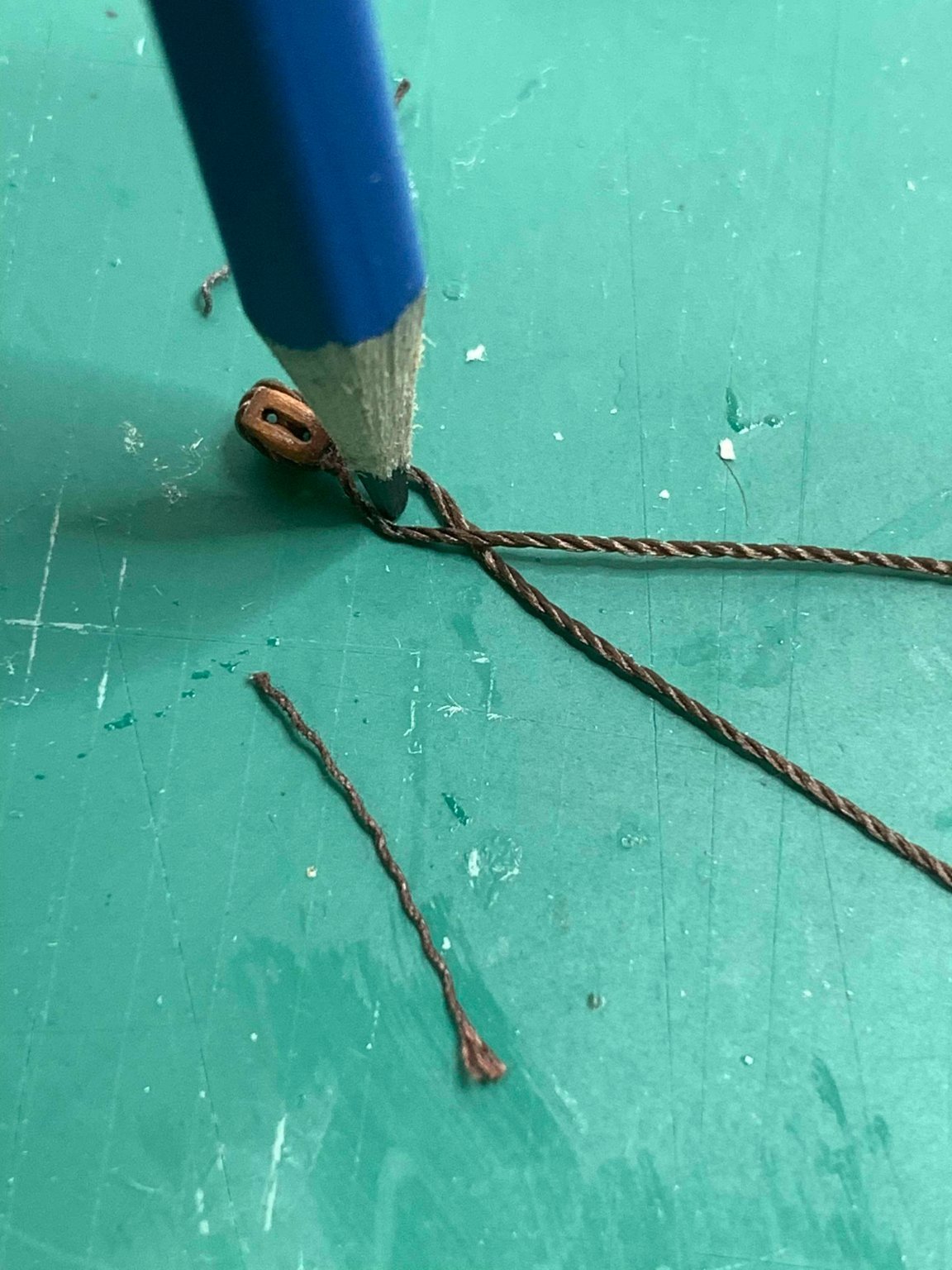
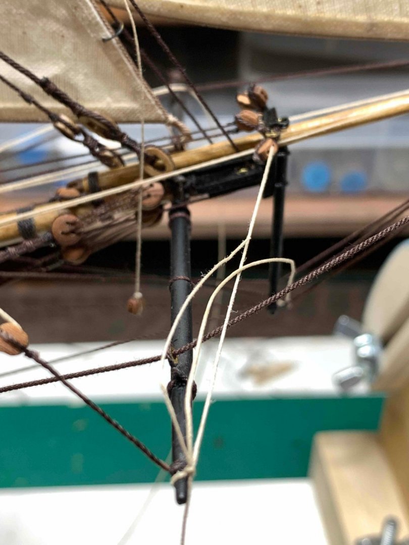
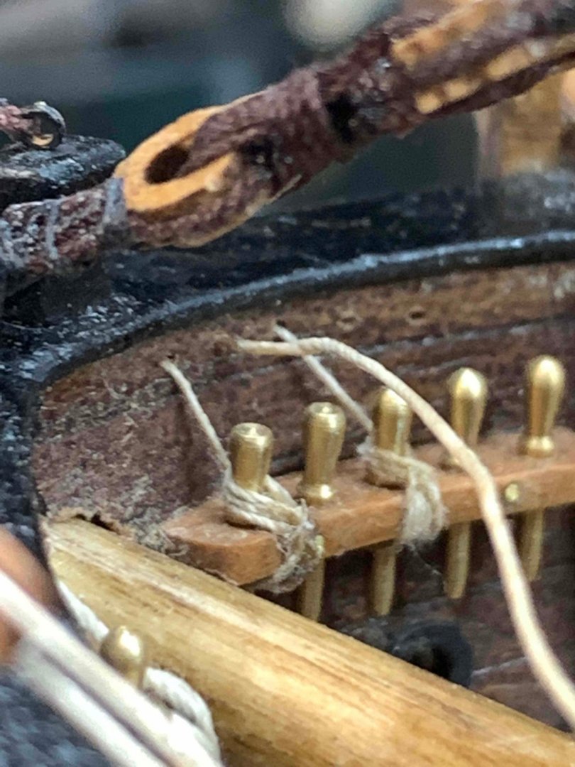
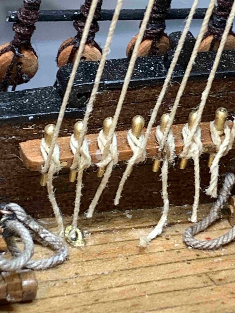
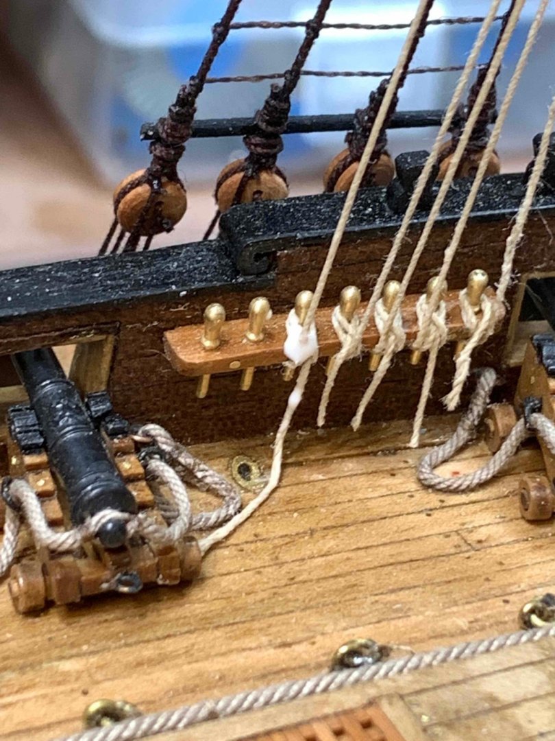
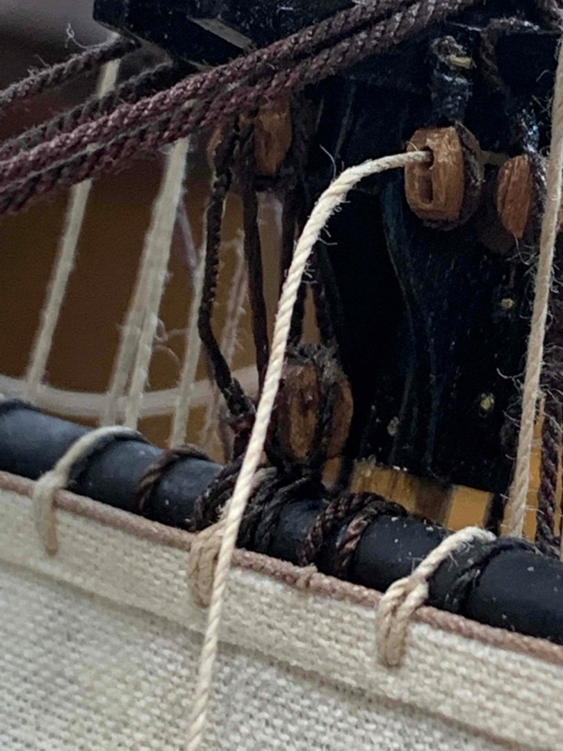
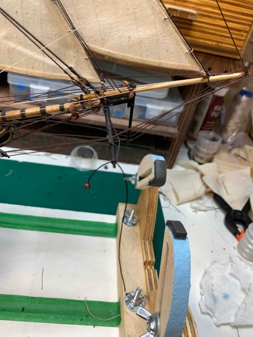
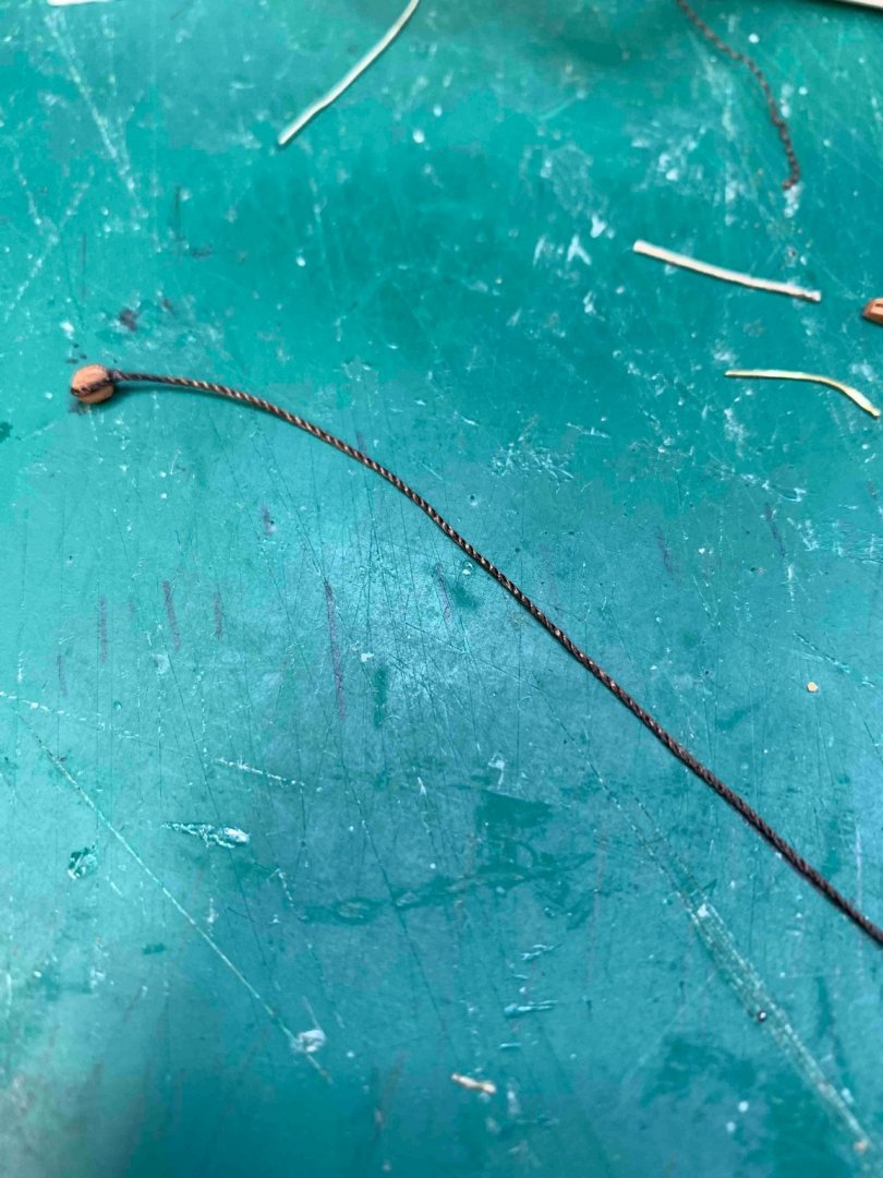
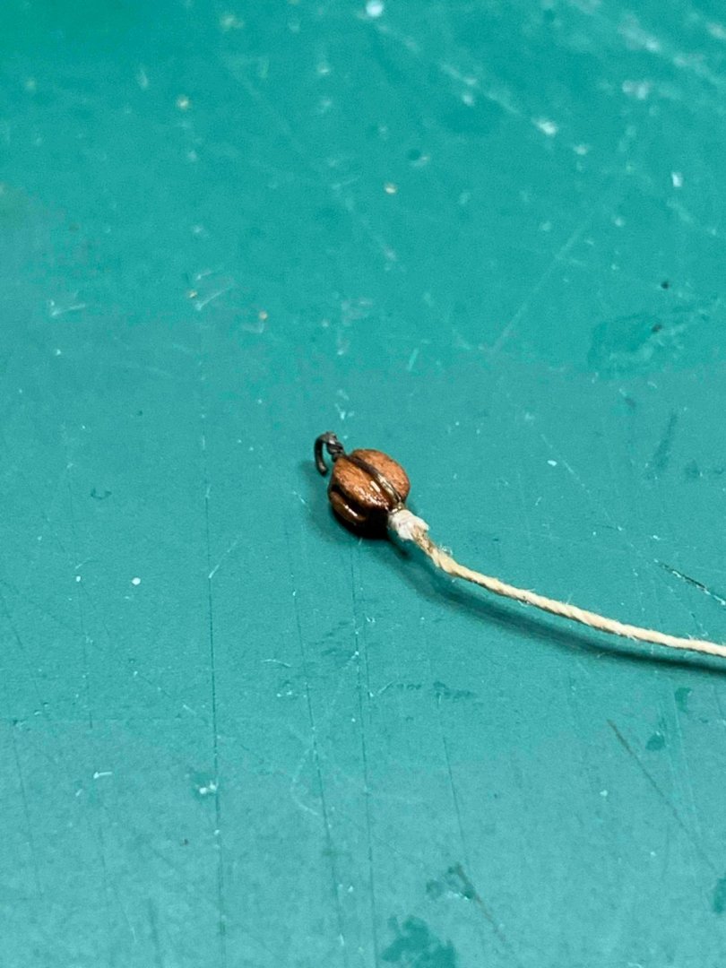
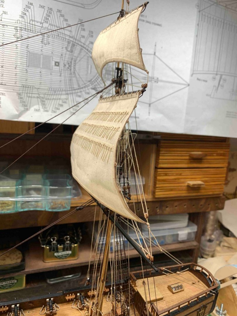
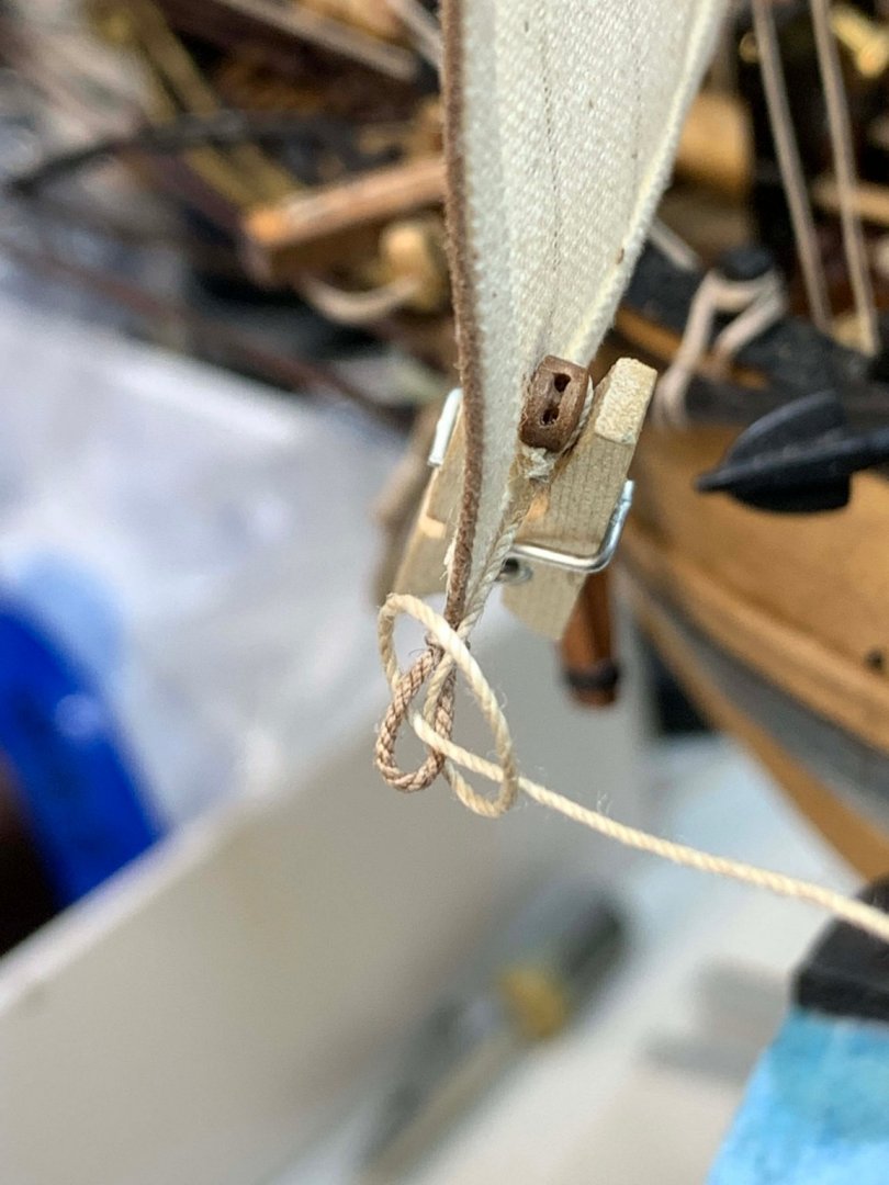
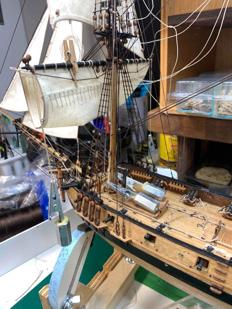
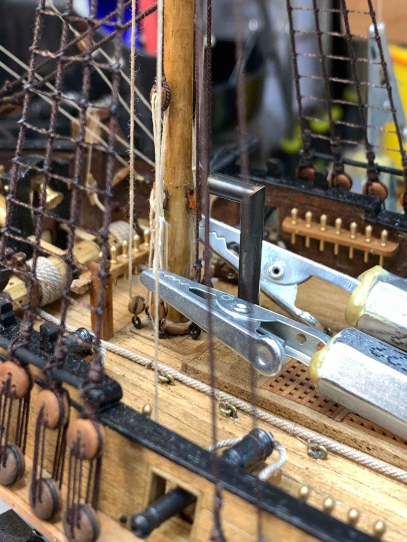
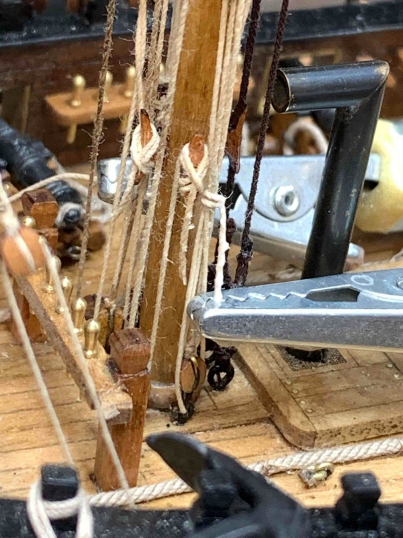
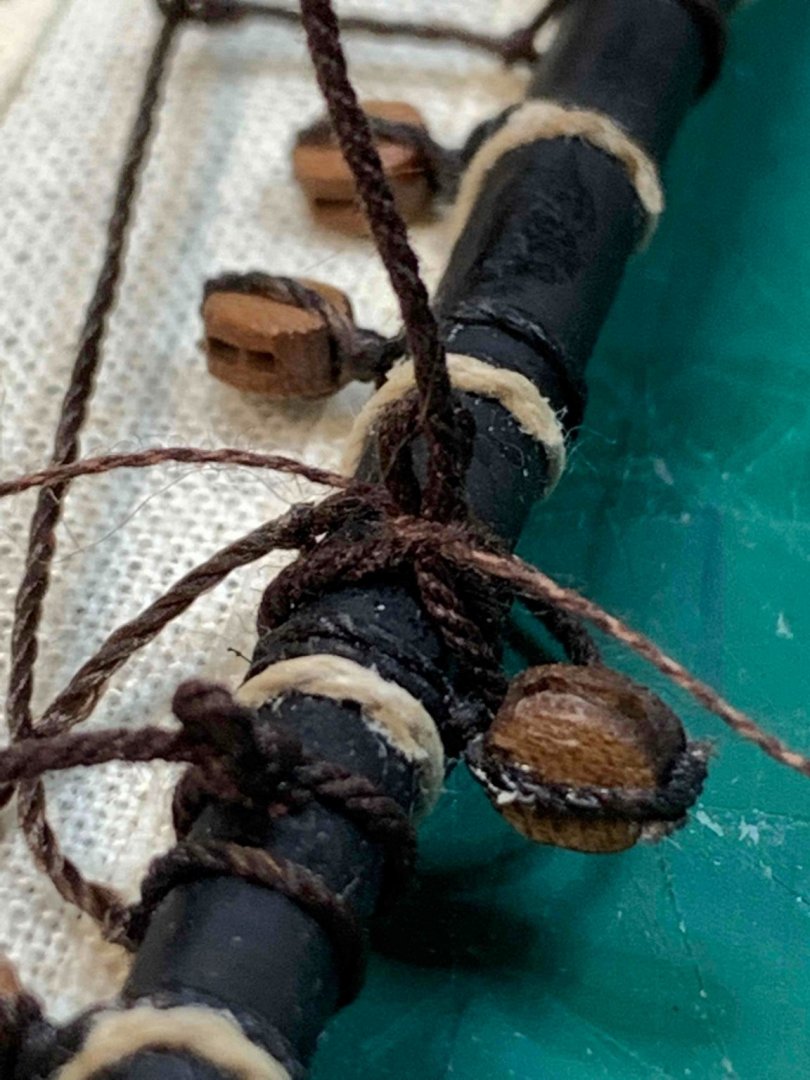
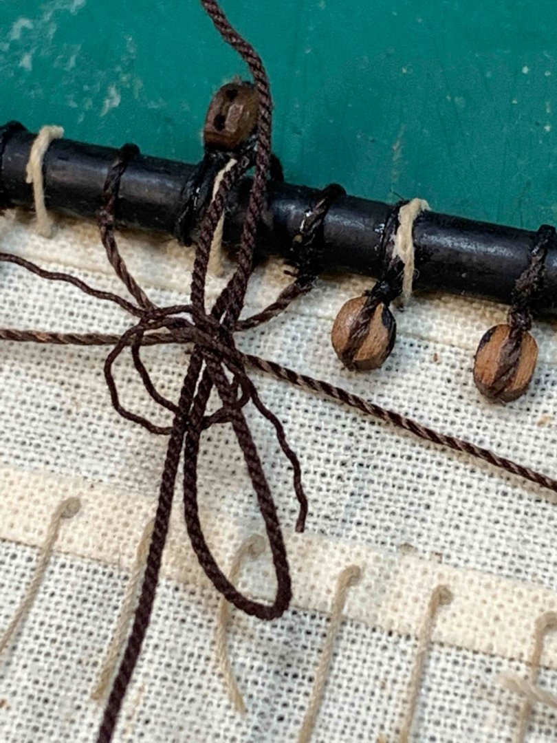
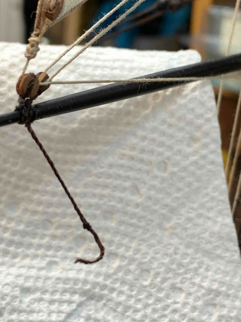
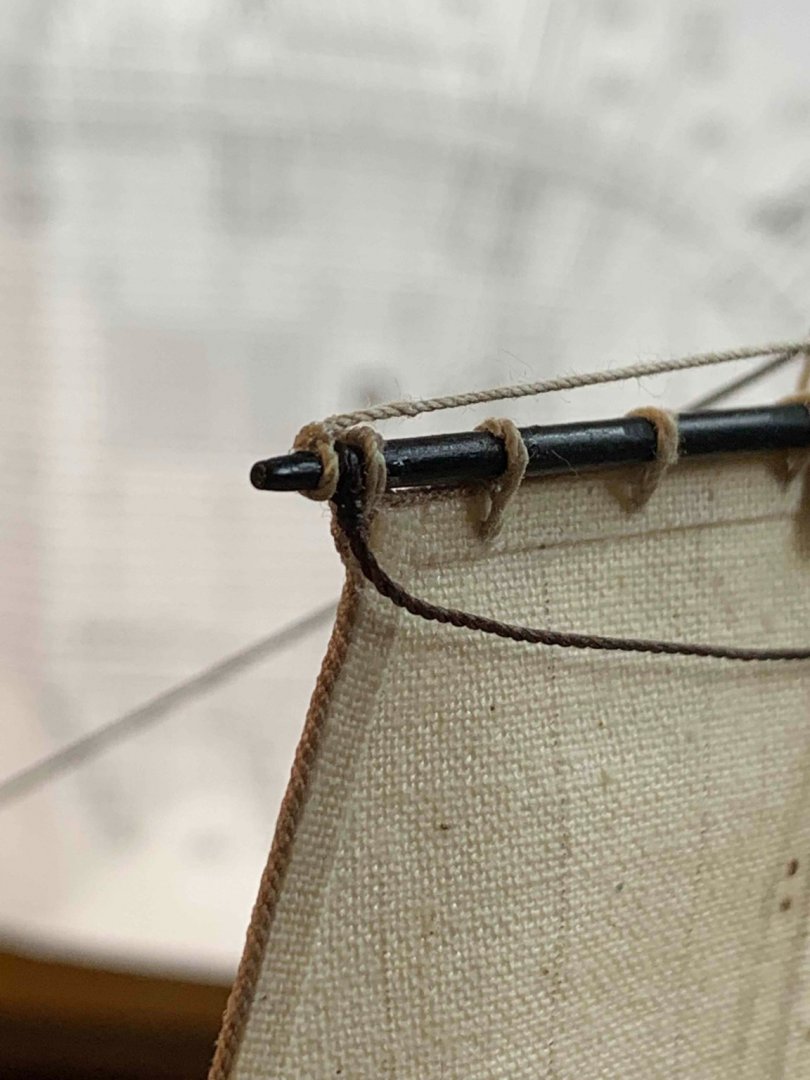
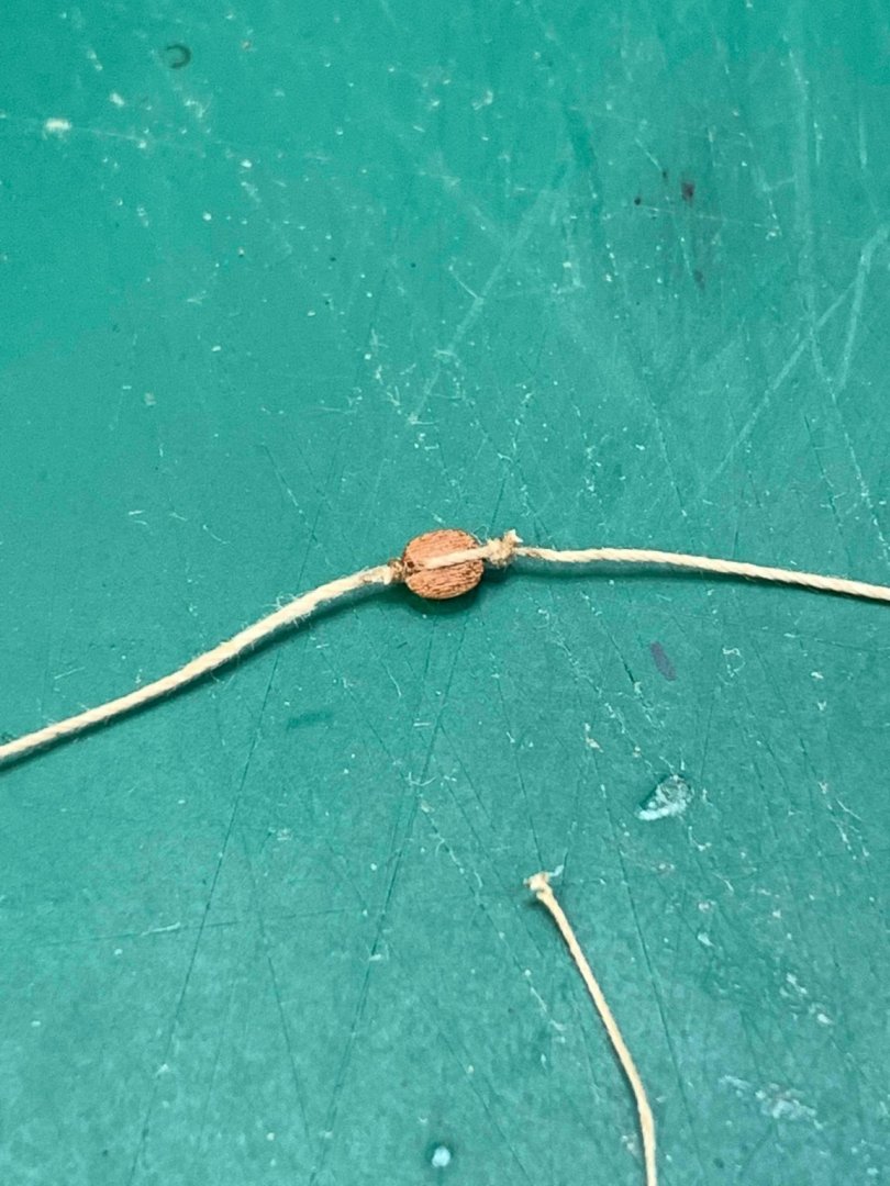
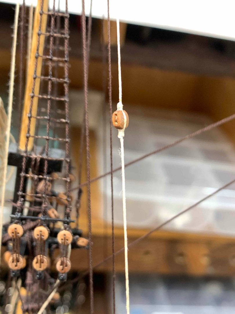
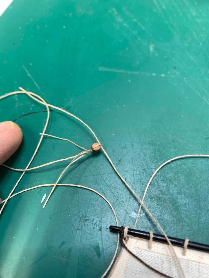
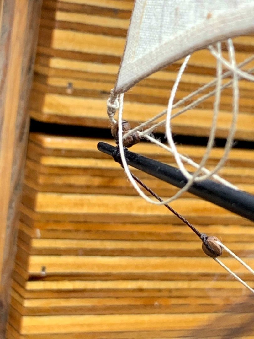
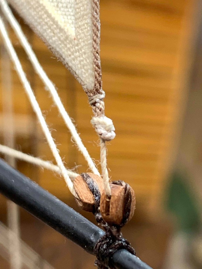
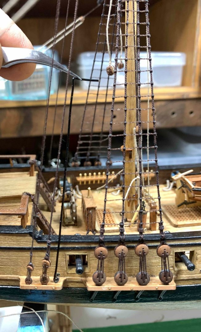
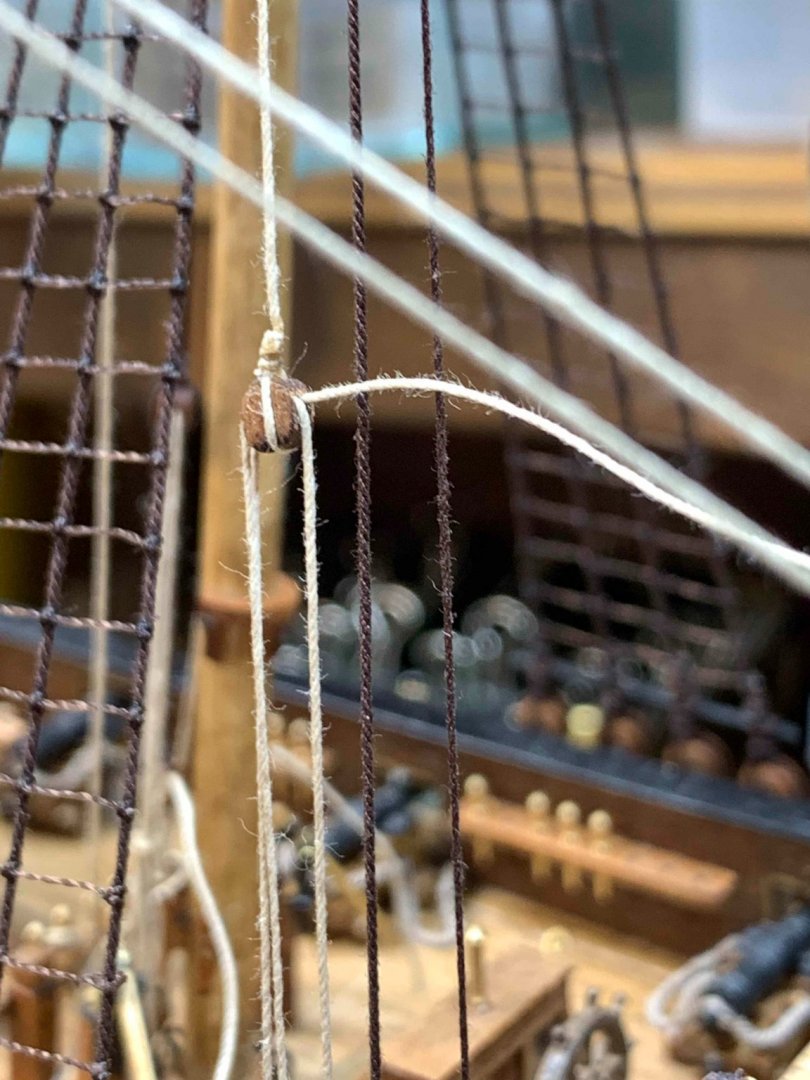
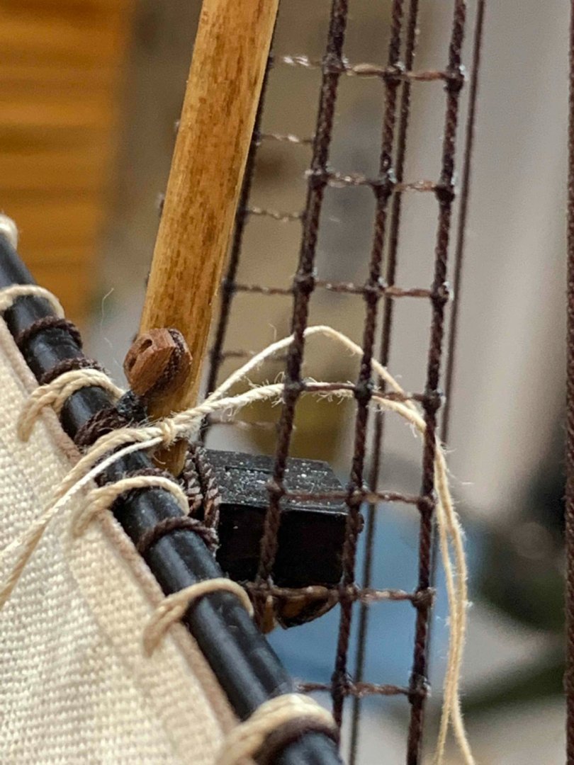
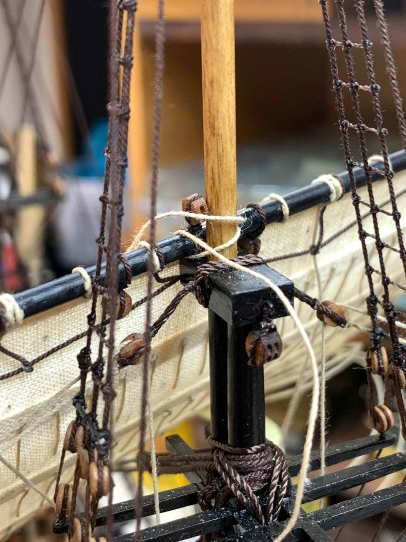
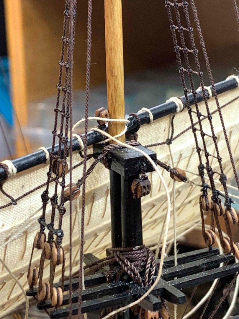
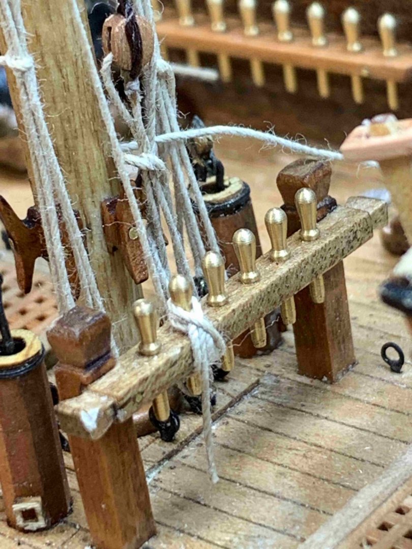
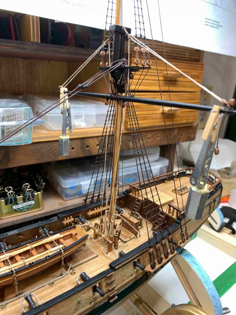
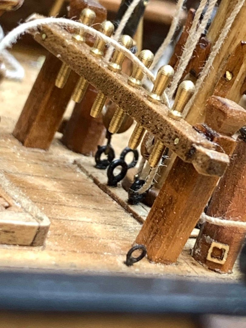
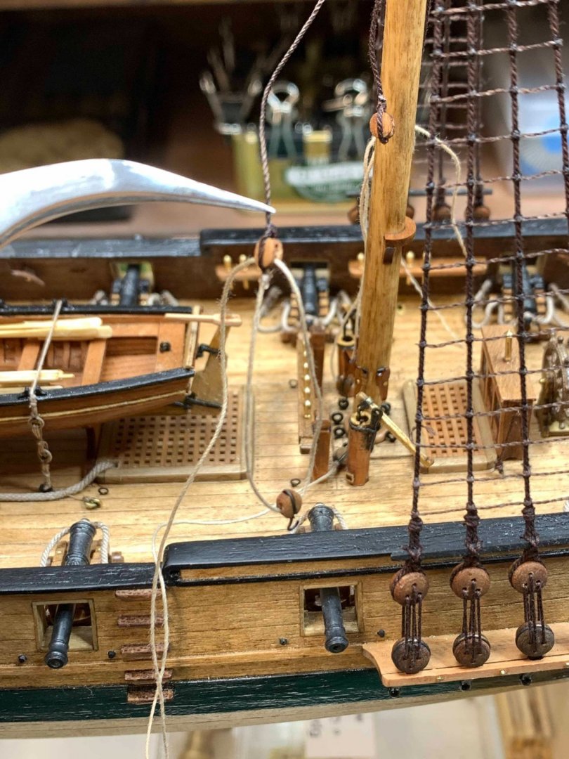
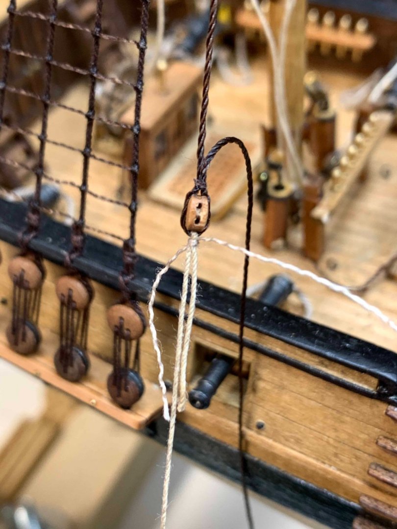
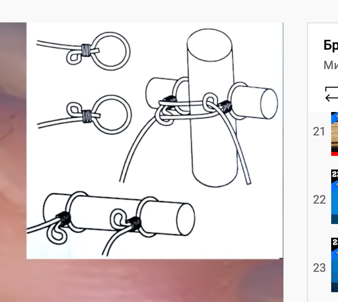
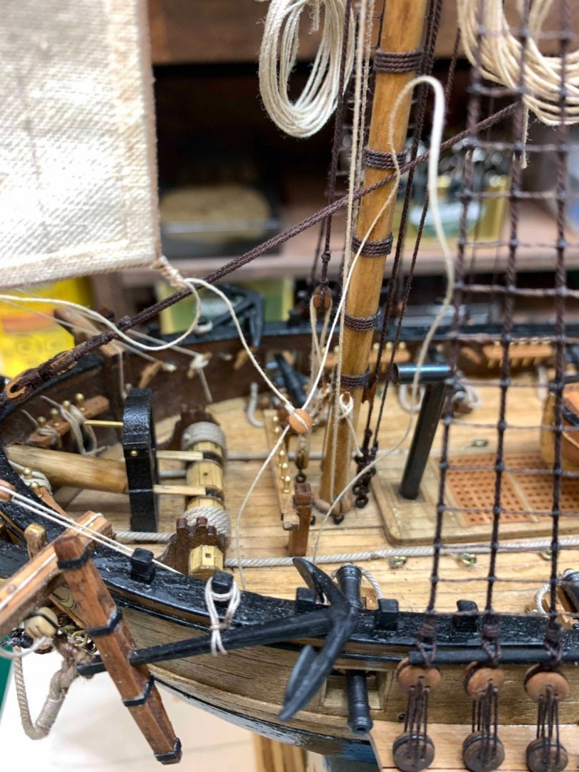
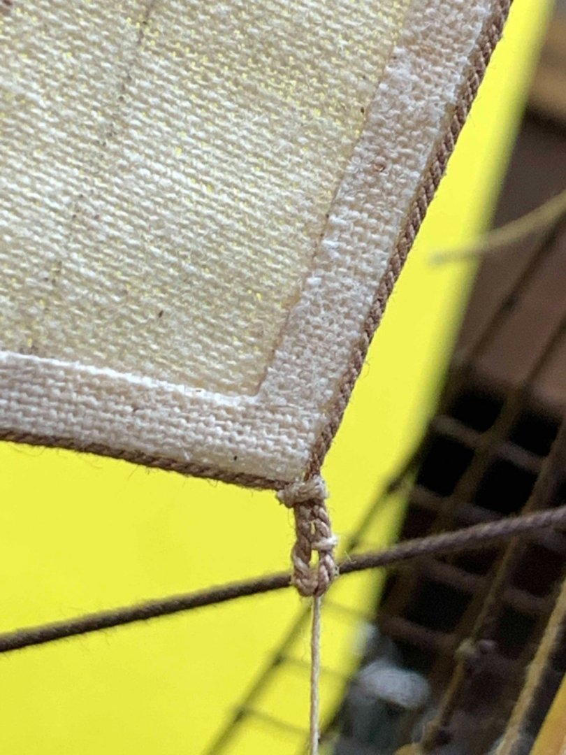
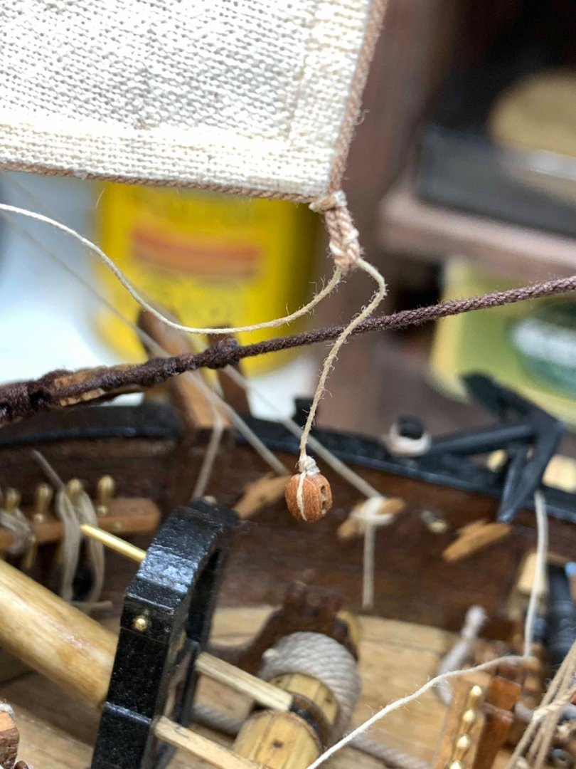
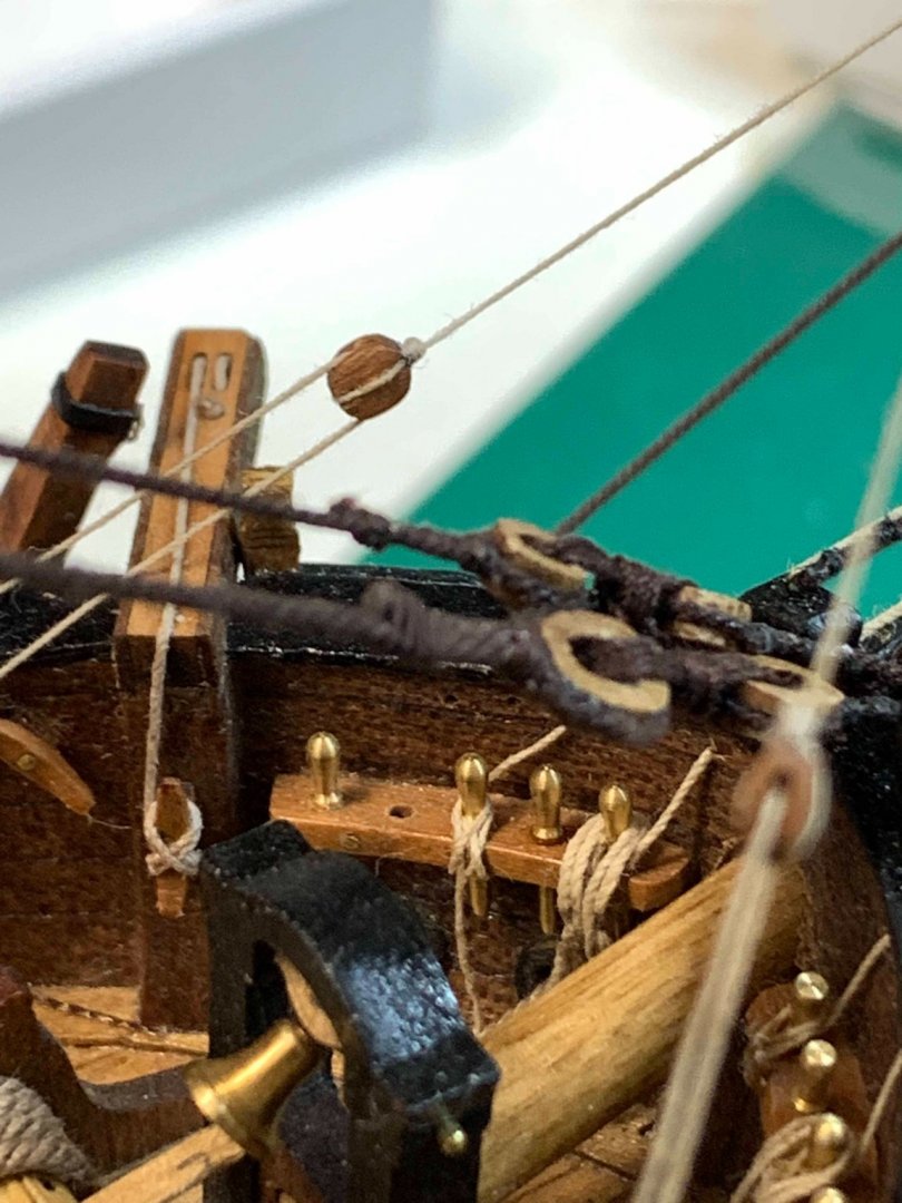
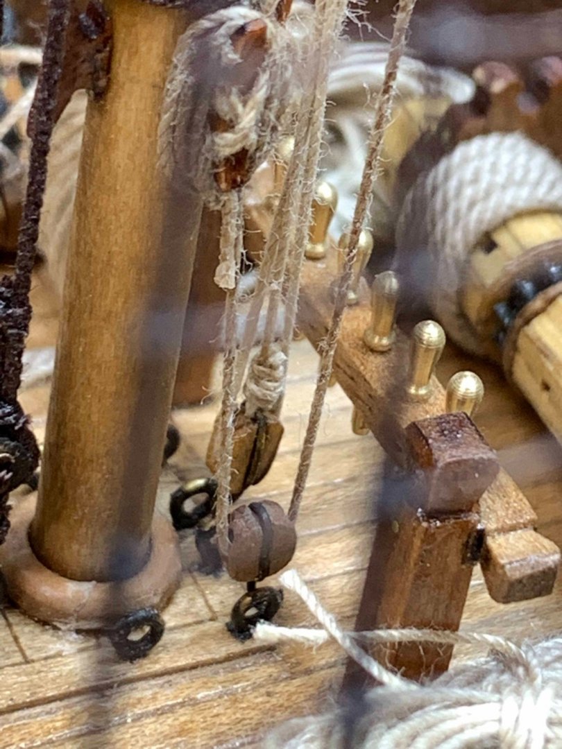
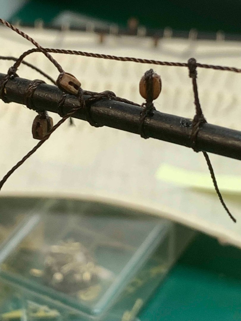
 I have tried a slightly different approach now... wanted to try starting the work from the pin, first tightening the rope around the pin and work towards the yards.. this will give me a bit more workspace and it might ended up better and more realistic.. So lets see... The rope was ran thru... .. the knot was tight around the pin... .. a bit of a CA was dropped to make sure the knot will stay in place.. Then the coil was attached, again with a help of a CA... The rope looks a bit fuzzy on zoomed picture but it was dragged thru a beeswax and from the naked eye it does look OK. So far it does look more realistic this way.. and easier to install... Then, the rope was running thru a block and attached to the sprit-sail yard.. Hmm, it does not look that bad after all... Will try few more times.. Happy modelling..
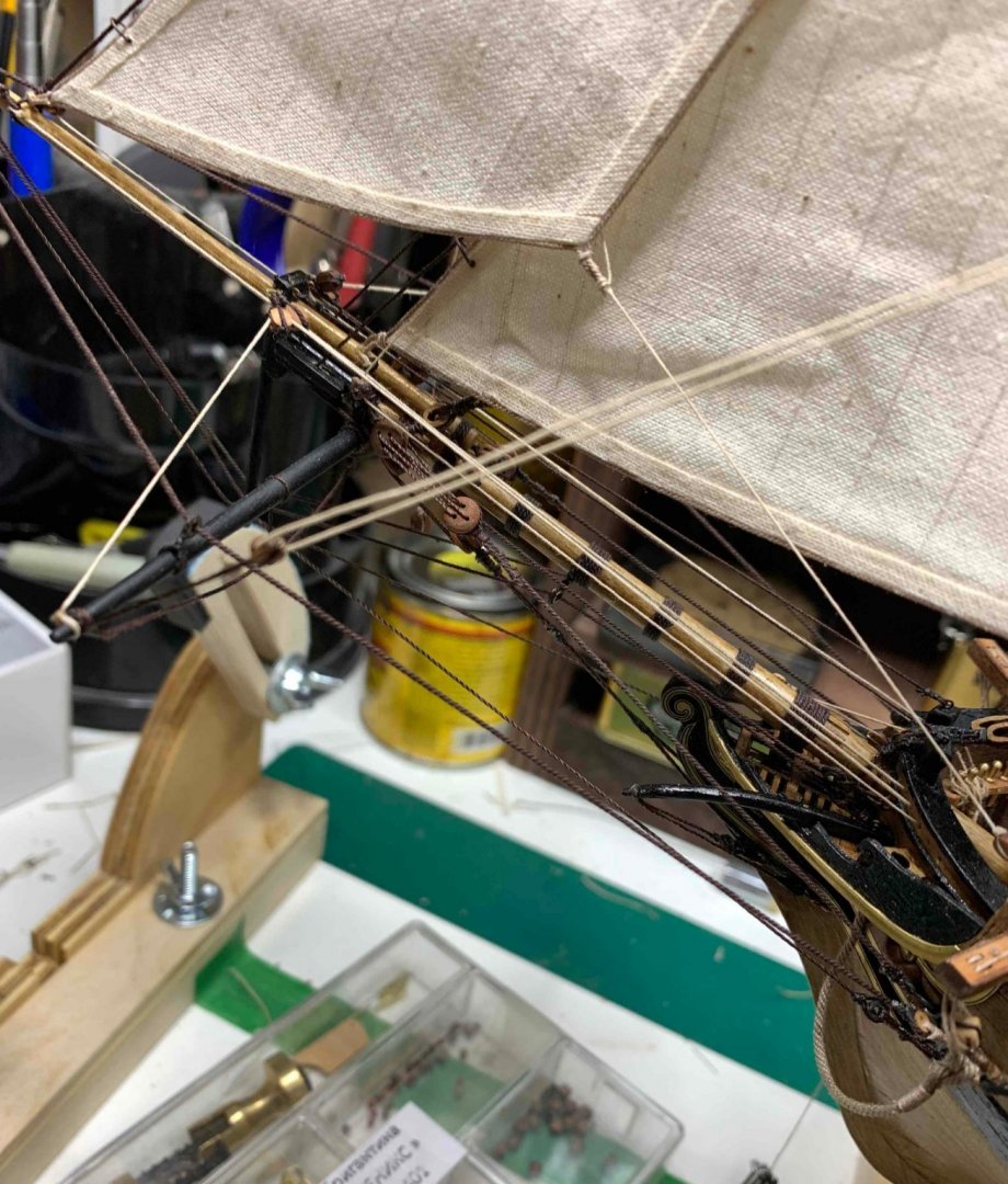

- 275 replies
-
- 3
-

-
- phoenix
- master korabel
- (and 1 more)
-
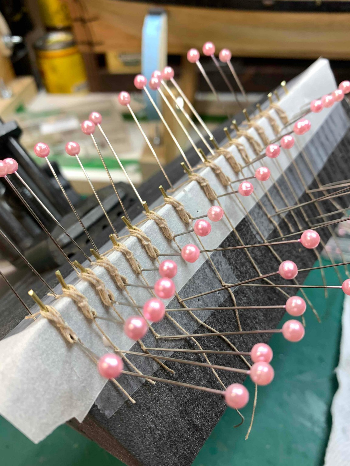
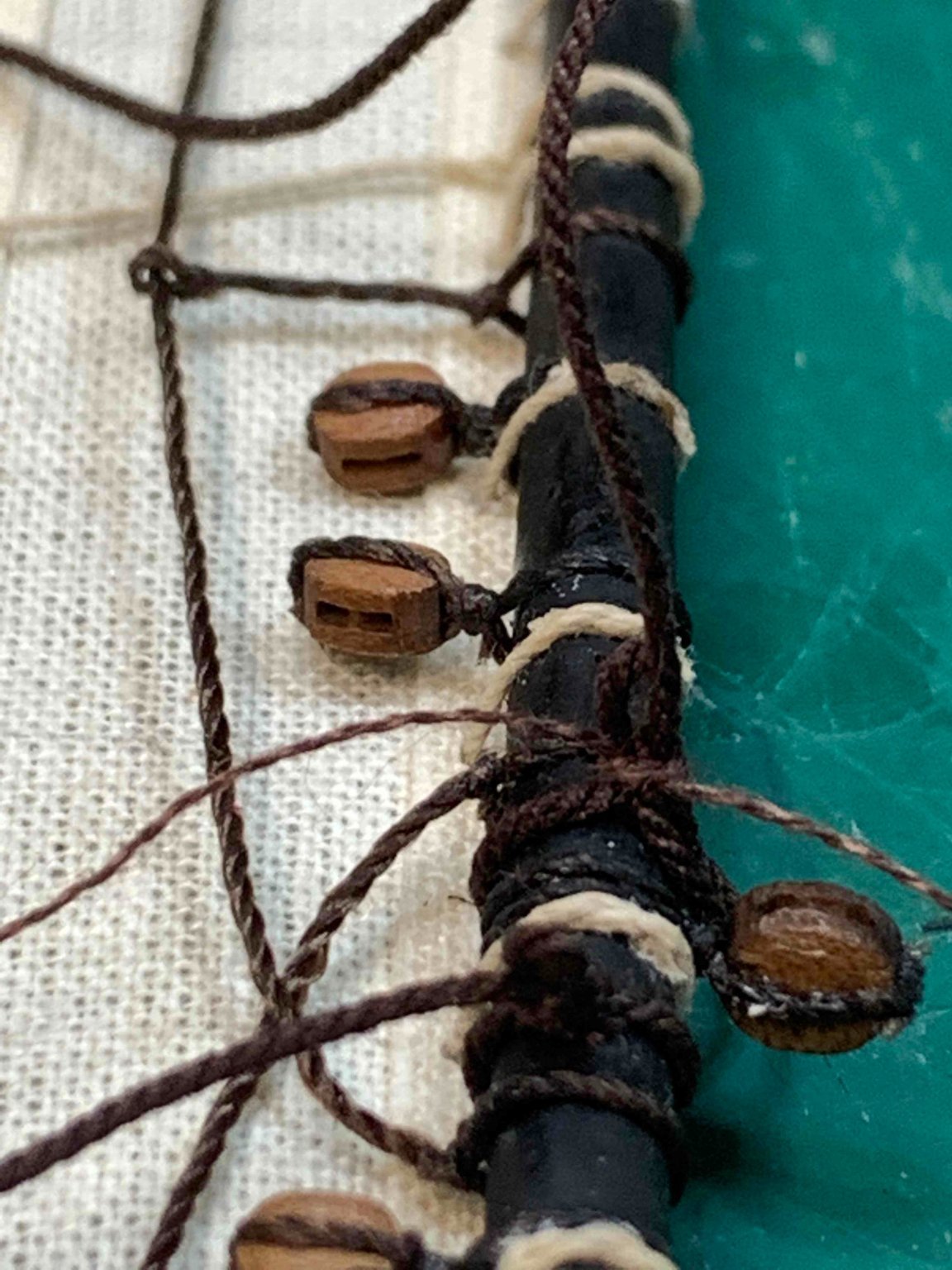
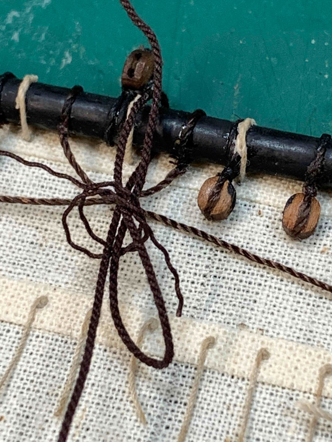
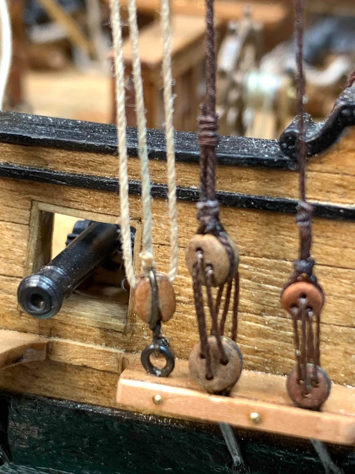
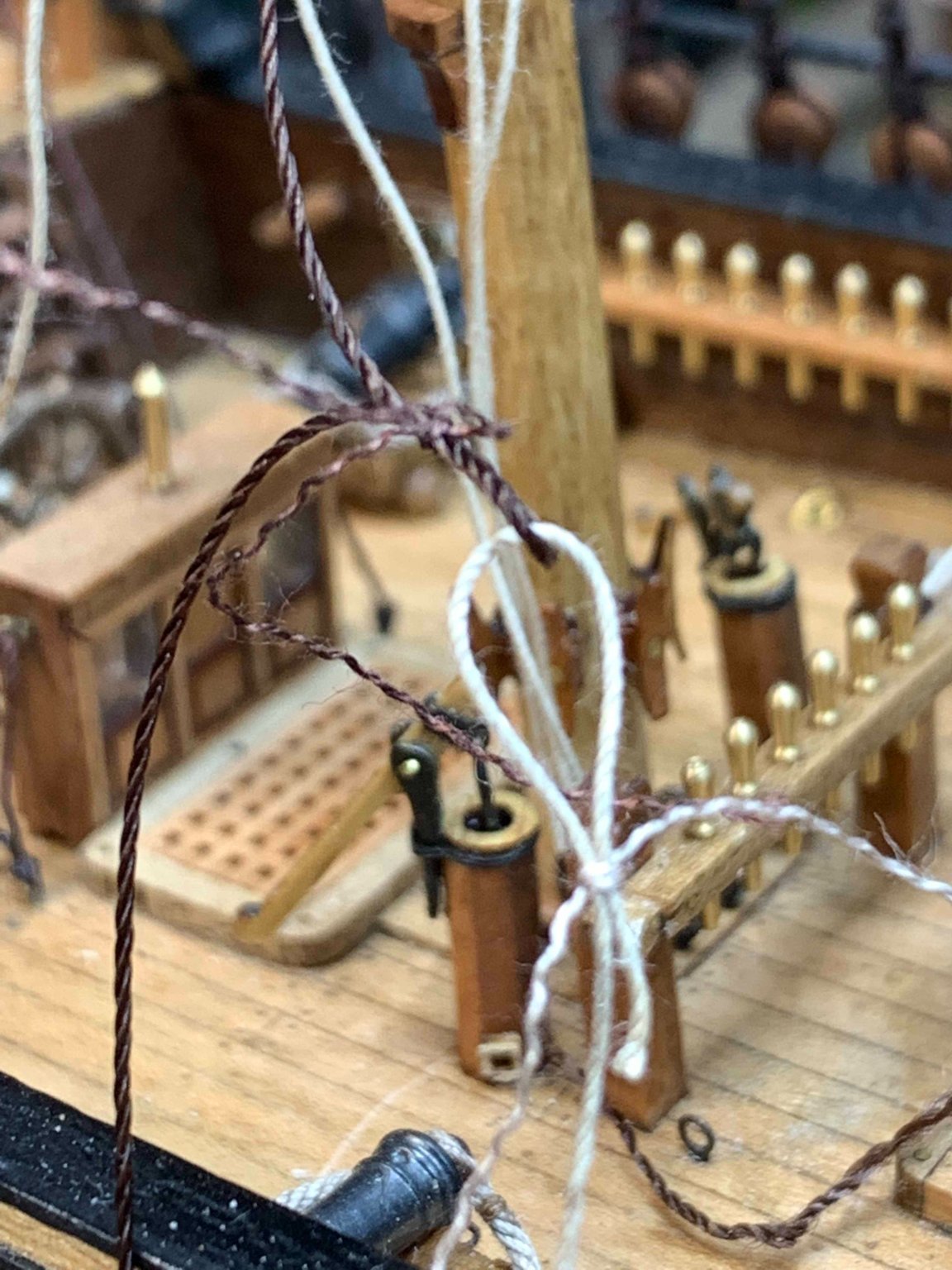
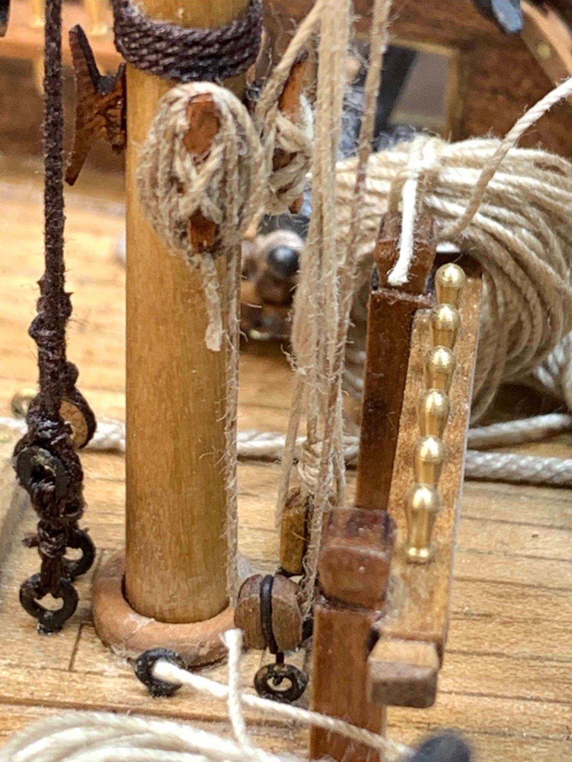
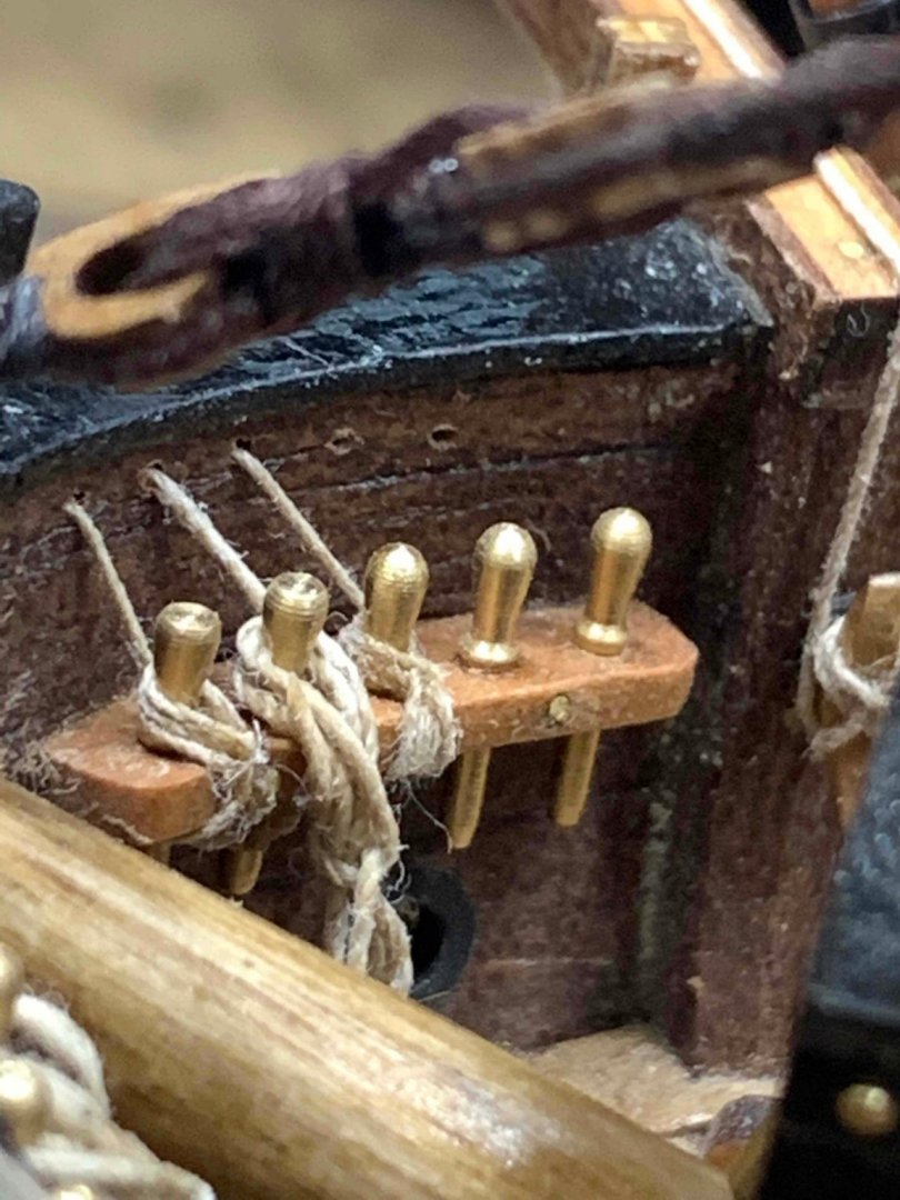
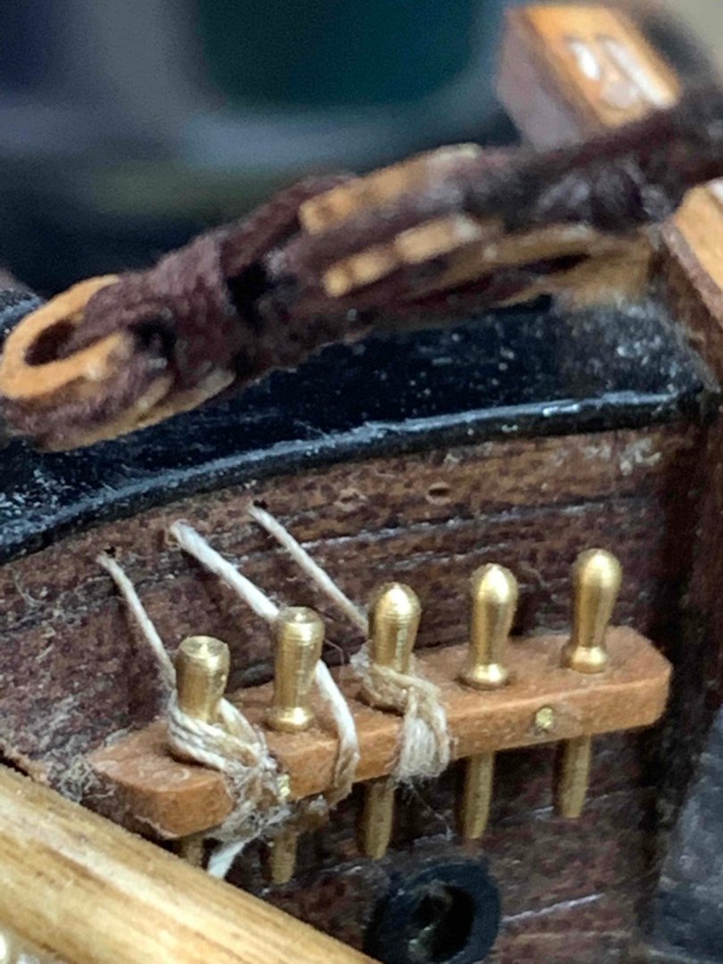
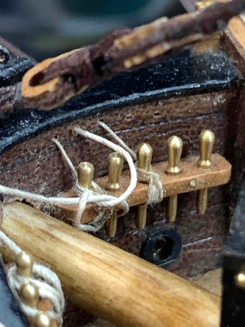
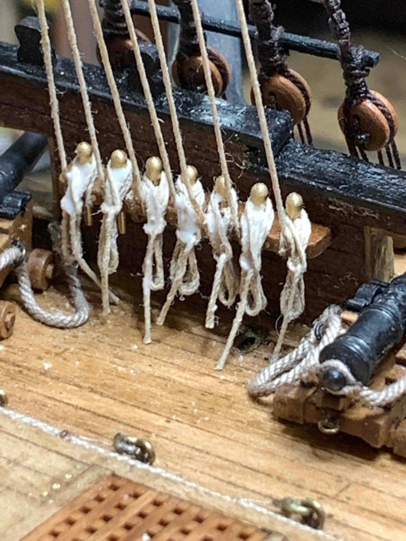
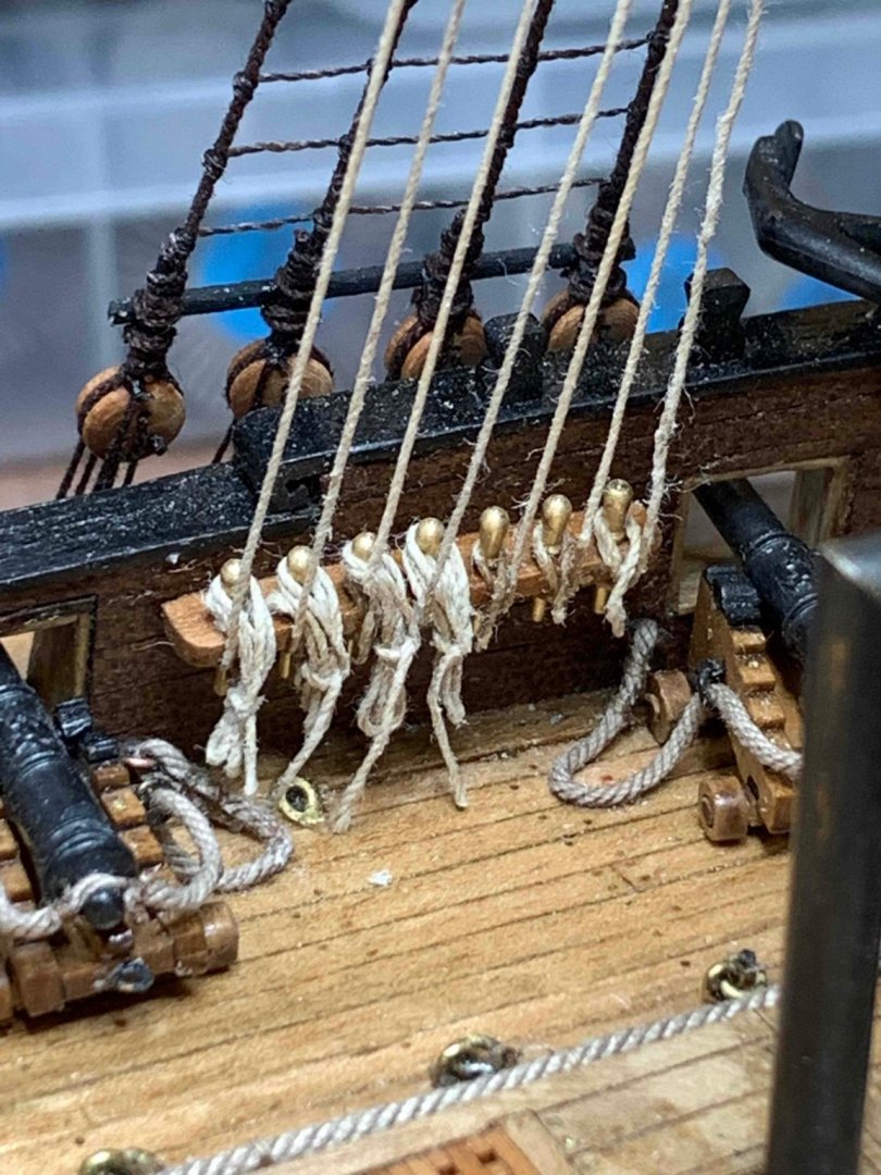
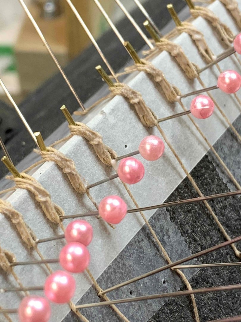
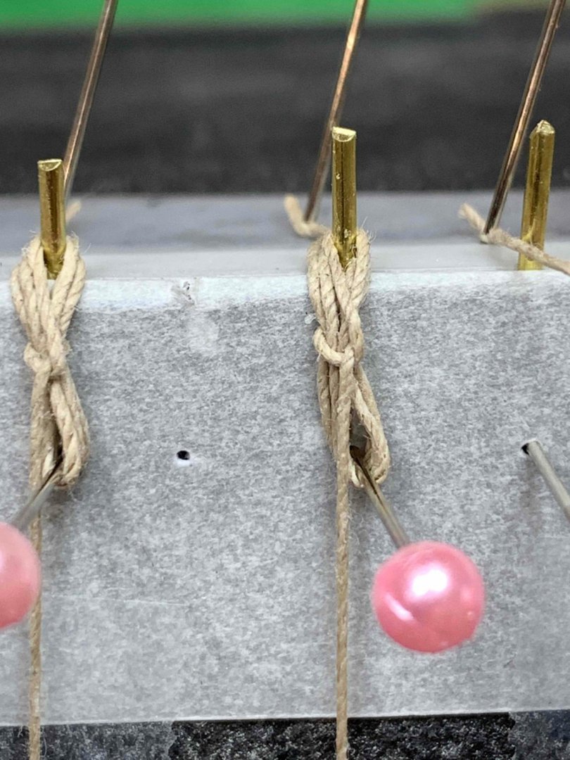
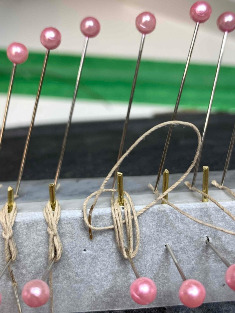
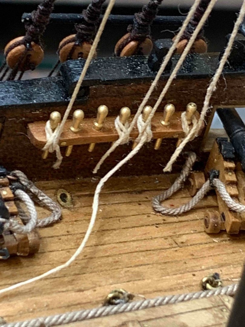
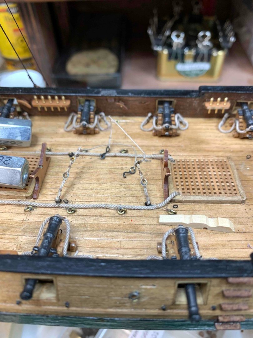
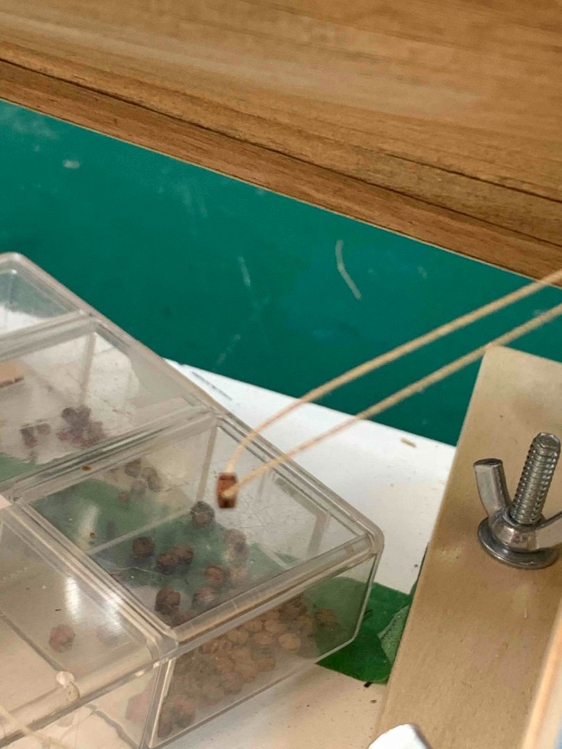
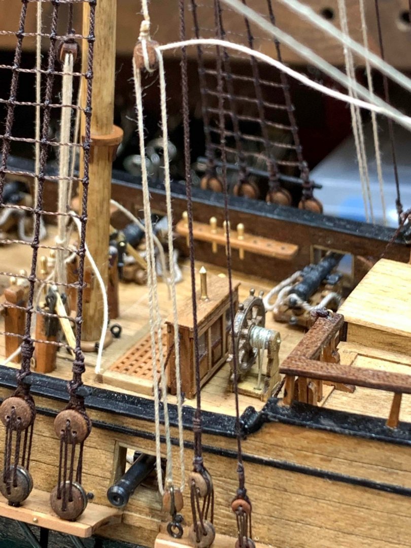
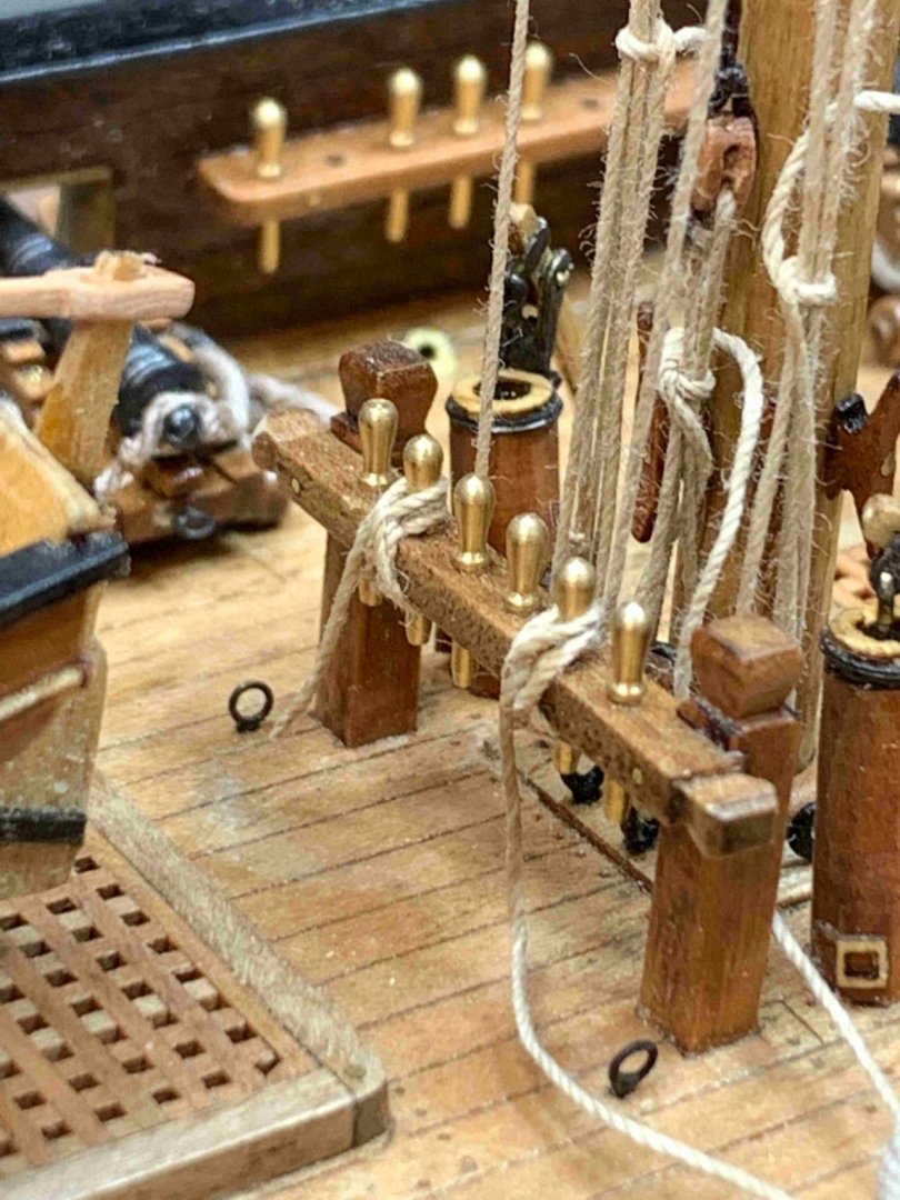
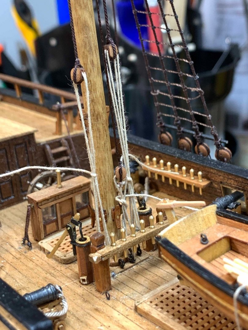
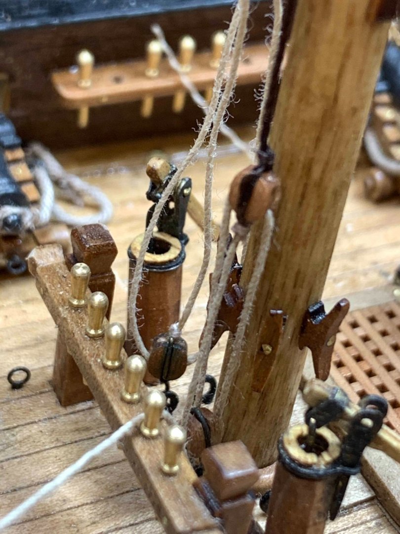
Did not quite like the way how all rope tail end ended up around belaying pins.. It is working just fine but the end results were not quite there so i decided to add a line coils... A bit of a different approach was also involved since i already cut all ropes to a length, so for me to lay the tail ends as they supposed to be, properly, coiled around the pins, was out of the question... First i a line coils factory... the flora craft foam was used as a foundation because of its sharp edges, and well, spongy structure, not hard to push all those small pins... The baking paper was used to prevent glue from sticking on the foam. To create a line coil diameter as close to the original pins diameter, i cut a 2mm wire into 1cm long "pins" and push into the foam.. The distance from the edge was measured from the pin location on the ship and hanging part was also measured to provide a nice look at the end... And started to run lines around it... A drop of white glue was put in each line coil to keep the shape and they were left to dry overnight.. End the results were OK.. A drop of diluted white glue was also applied on the final product.. There are definitely other ways of doing this exercise and the best way will be to do the line coils on the ship directly, but this scale is fairly small for my fingers... Maybe next time.. Happy modelling..


- 275 replies
-
- 3
-
-
- phoenix
- master korabel
- (and 1 more)
-
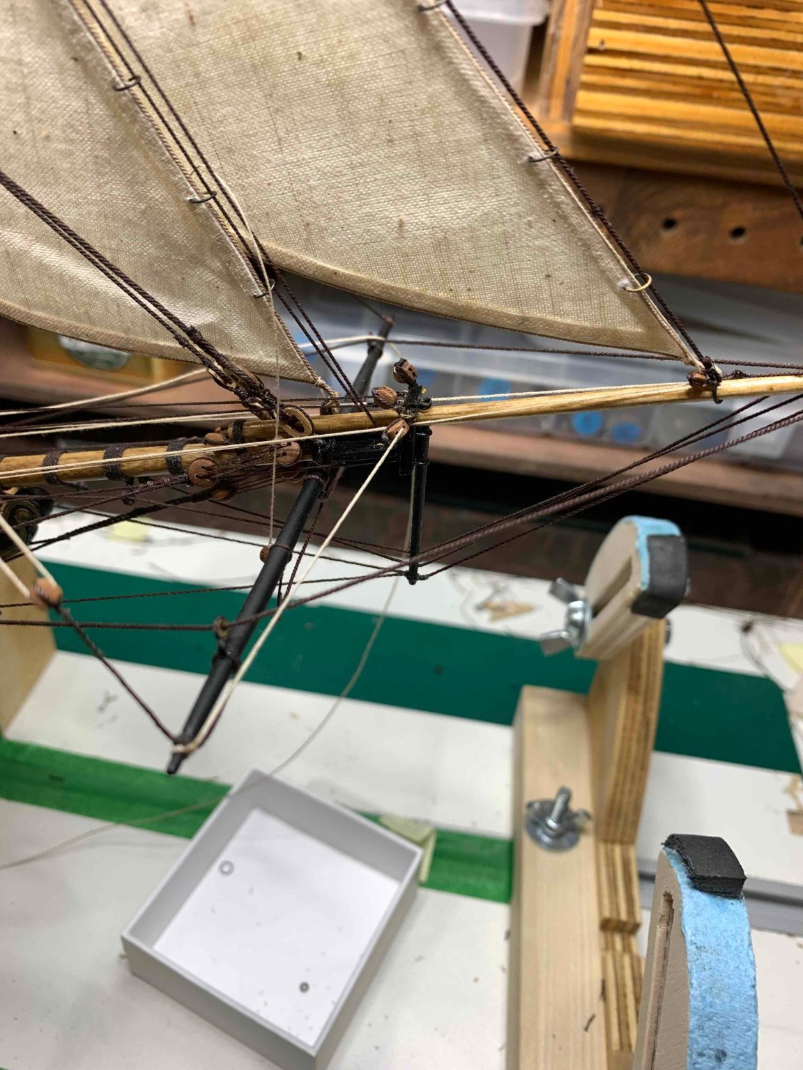
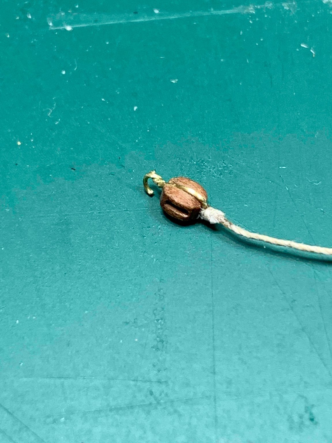
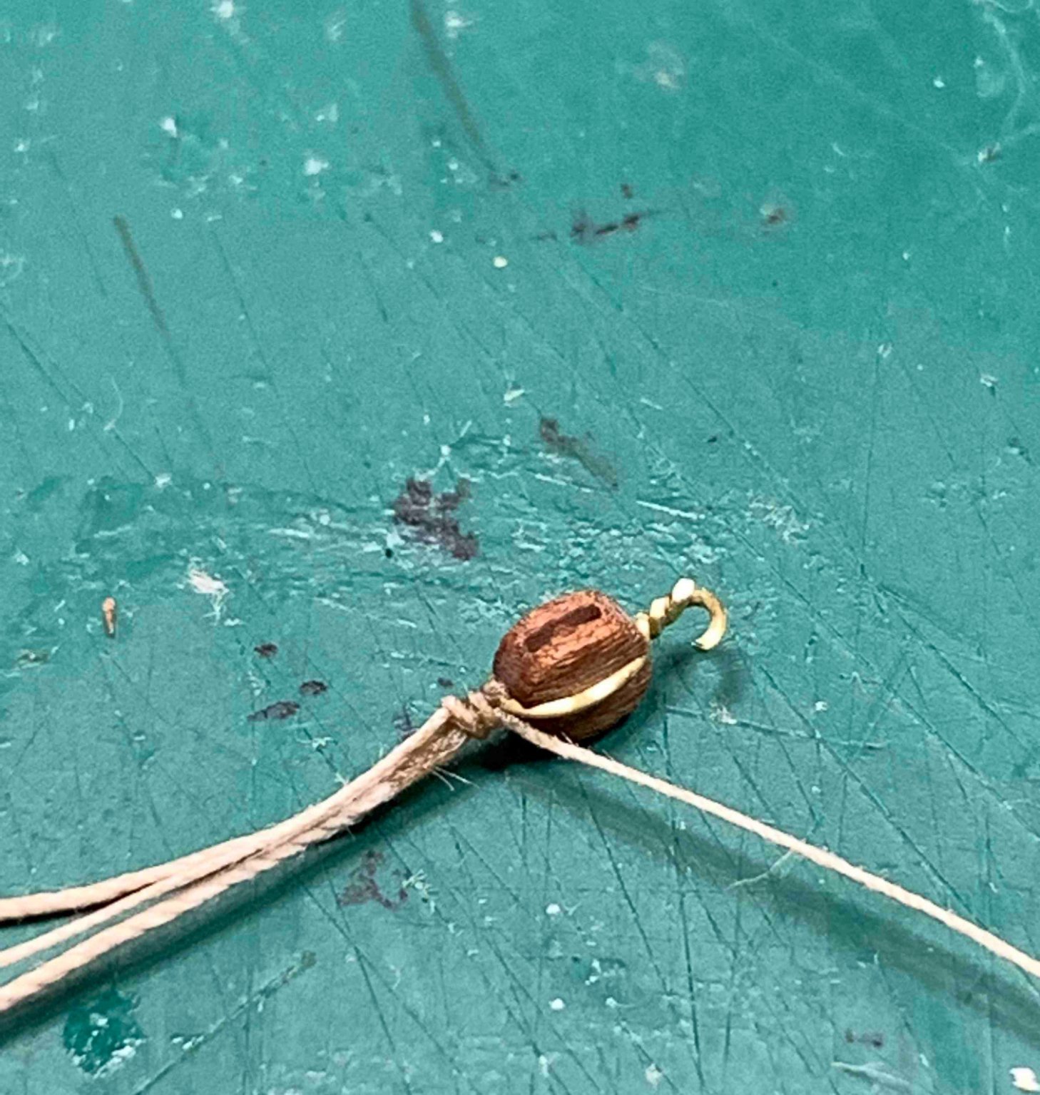
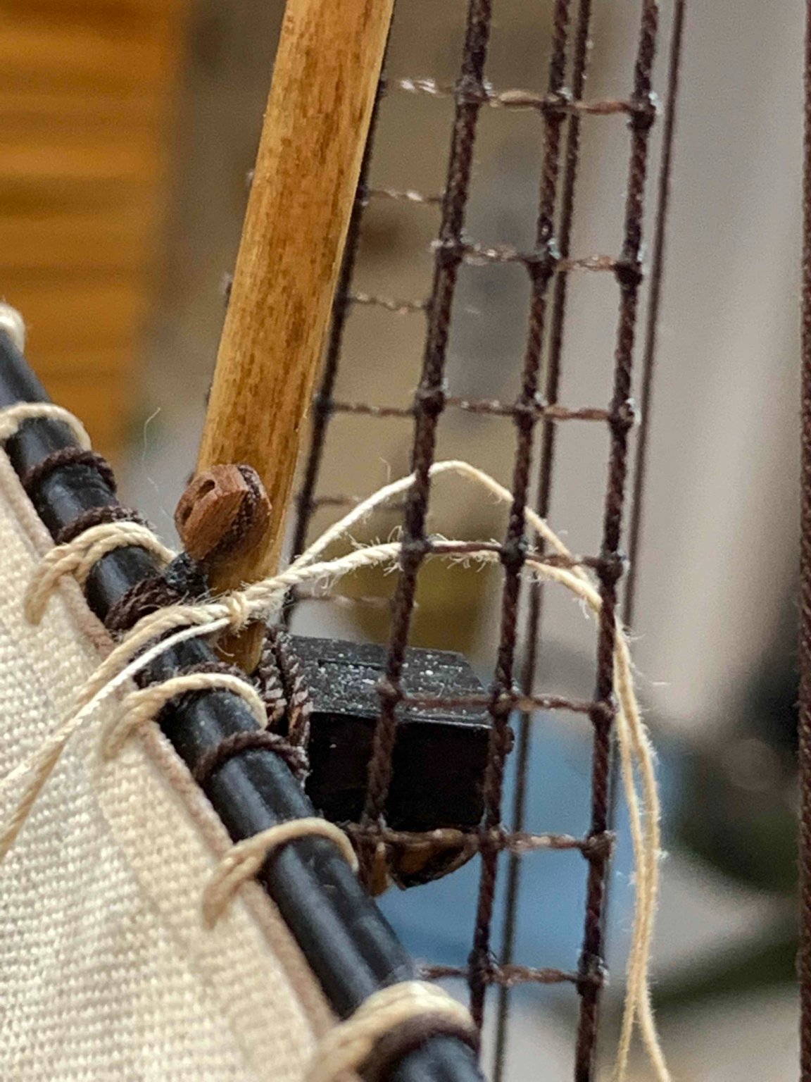
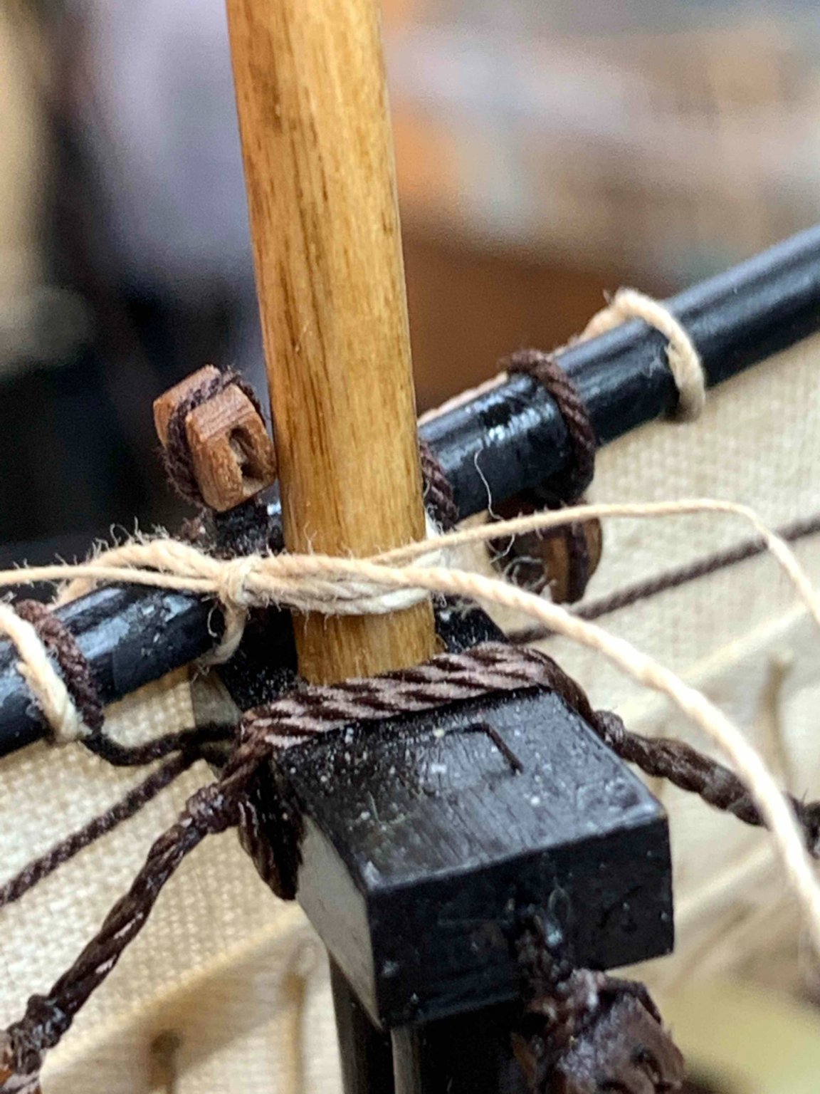
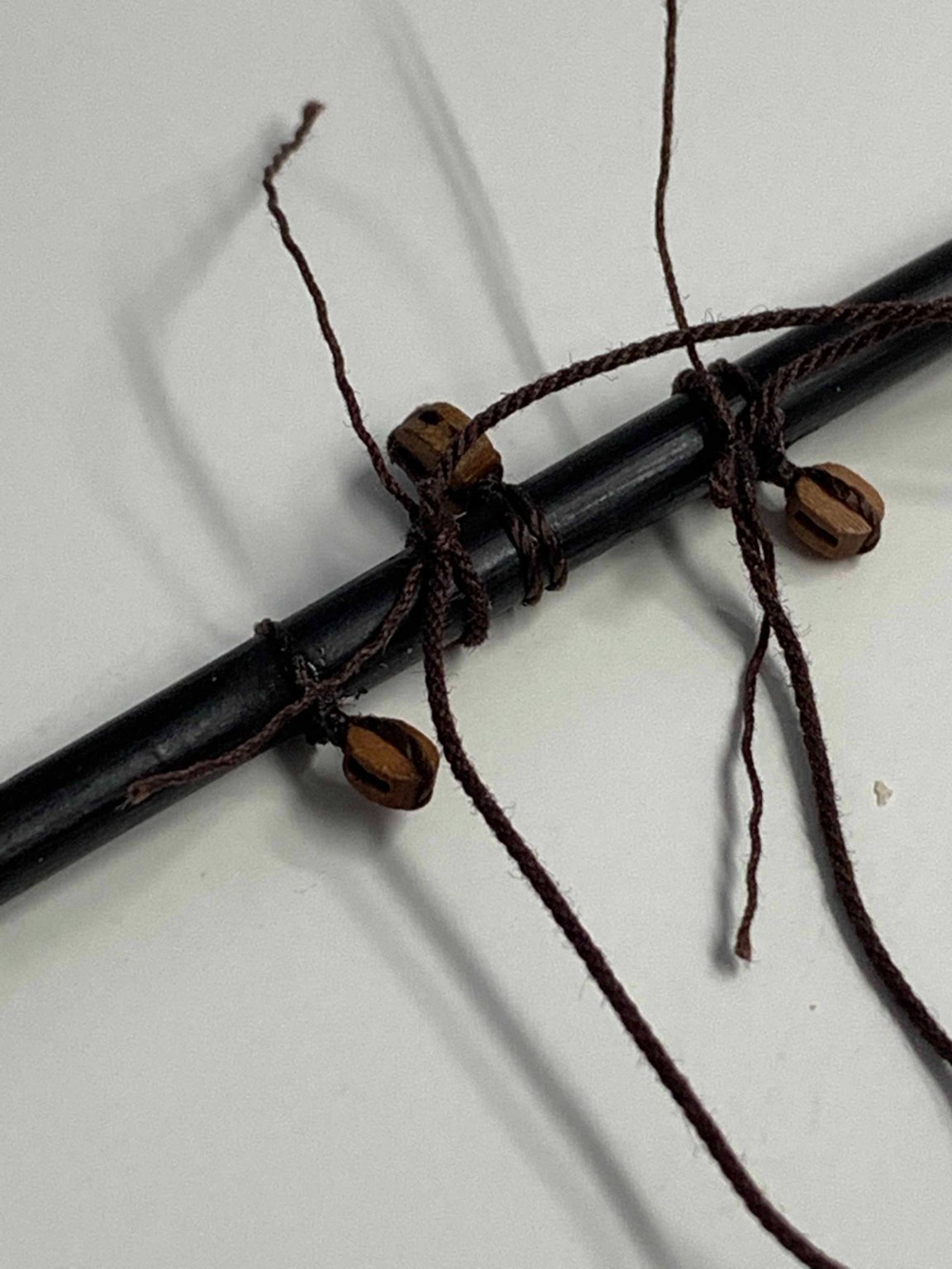
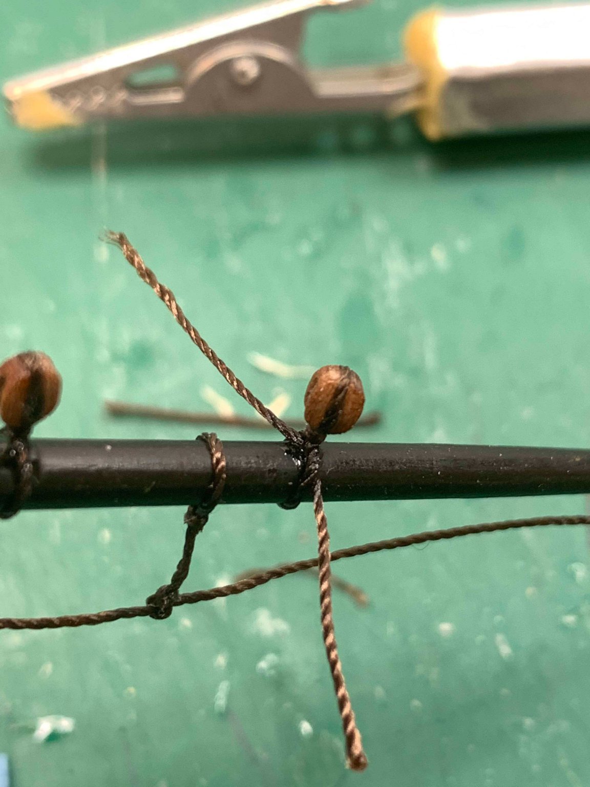
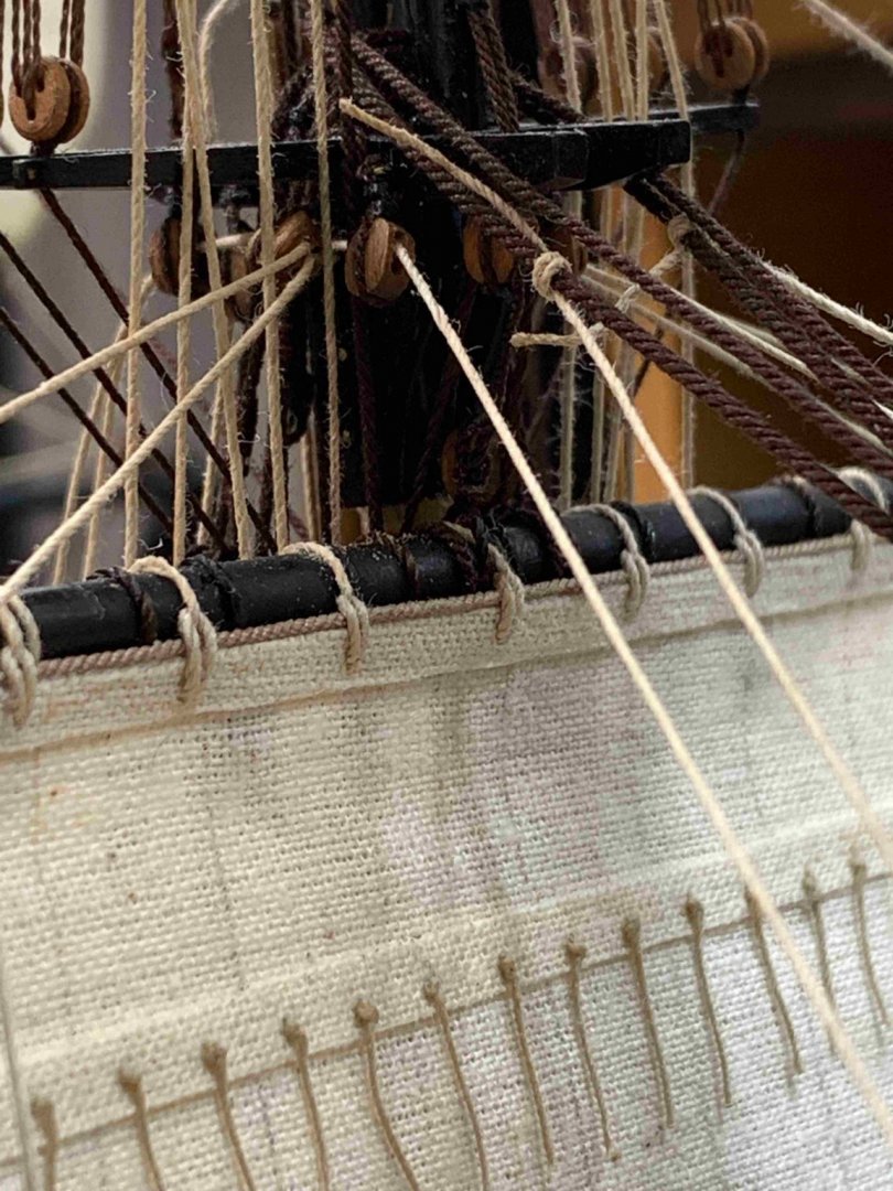
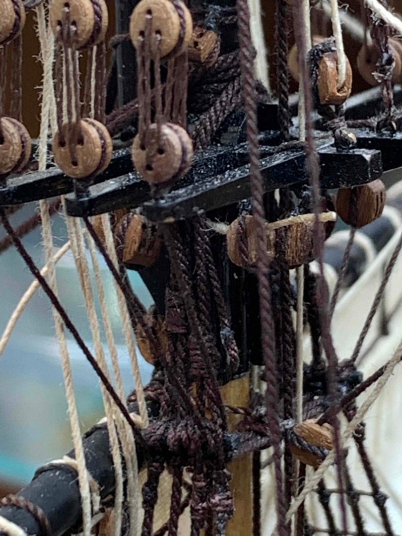
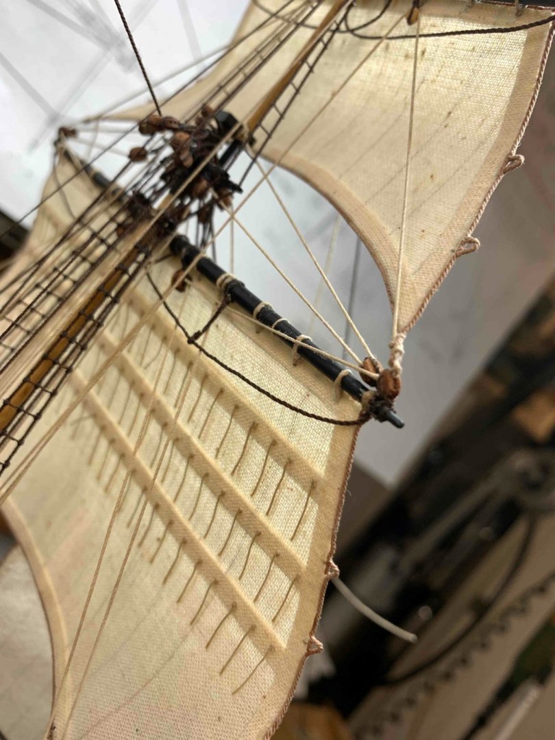
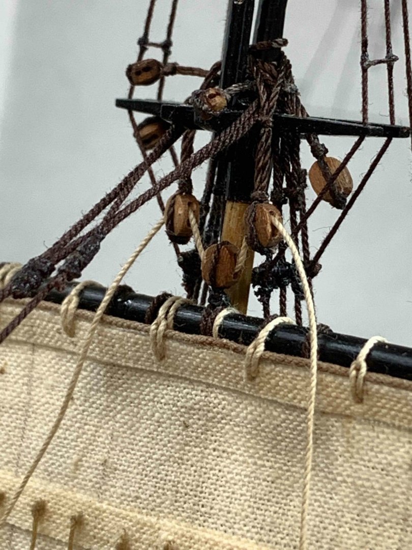
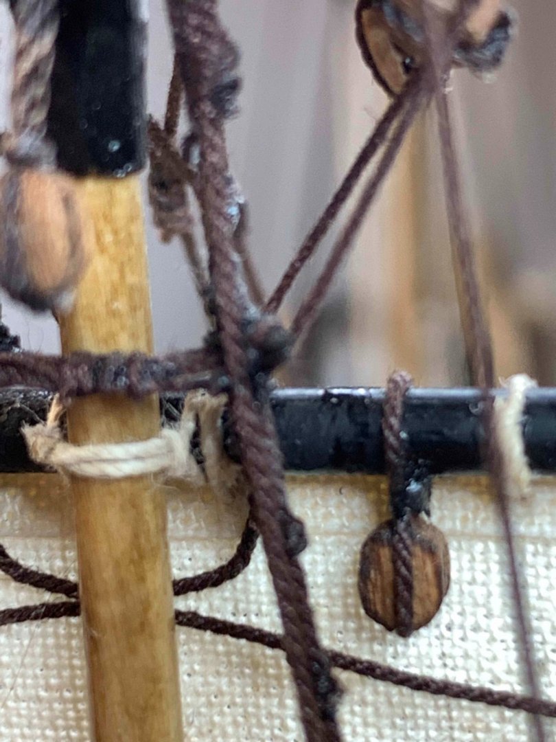
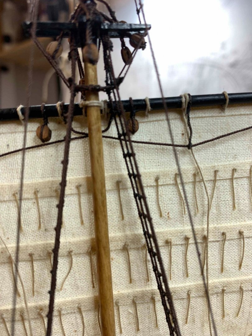
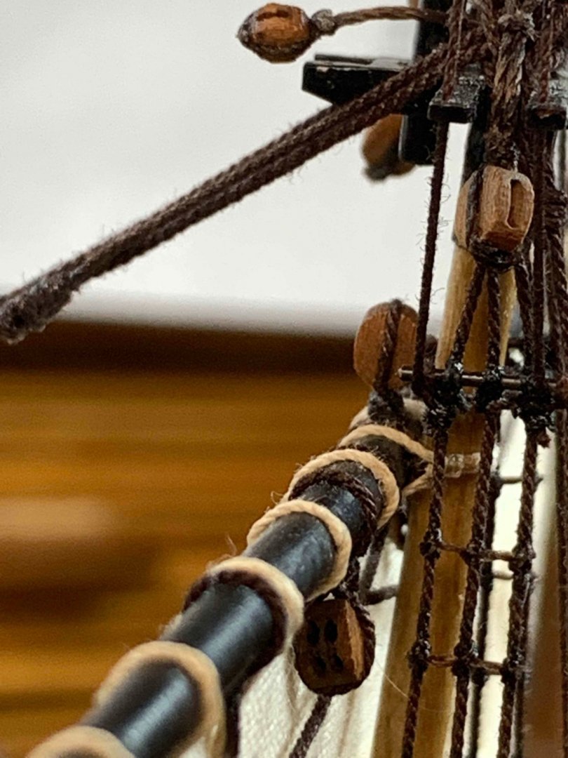
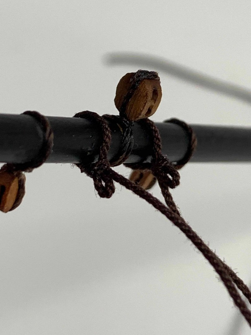
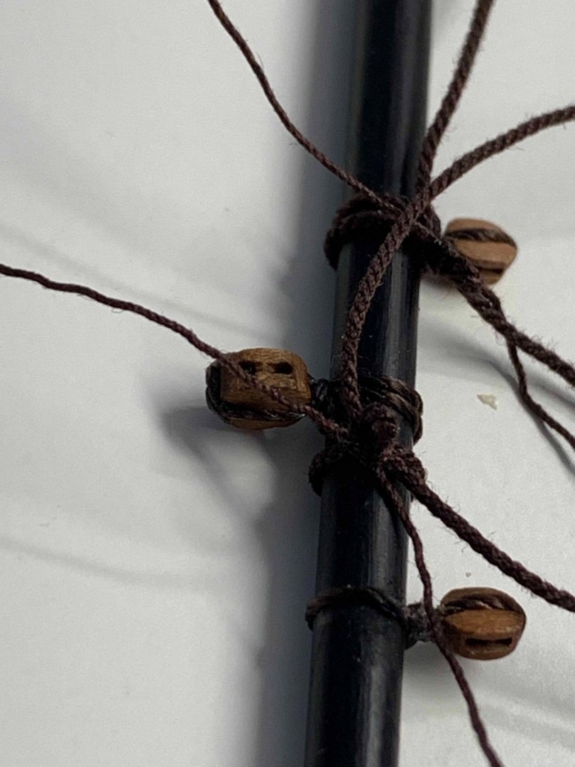
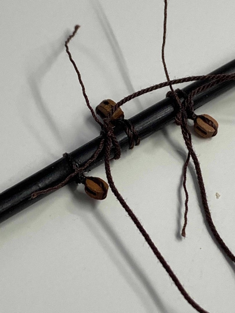
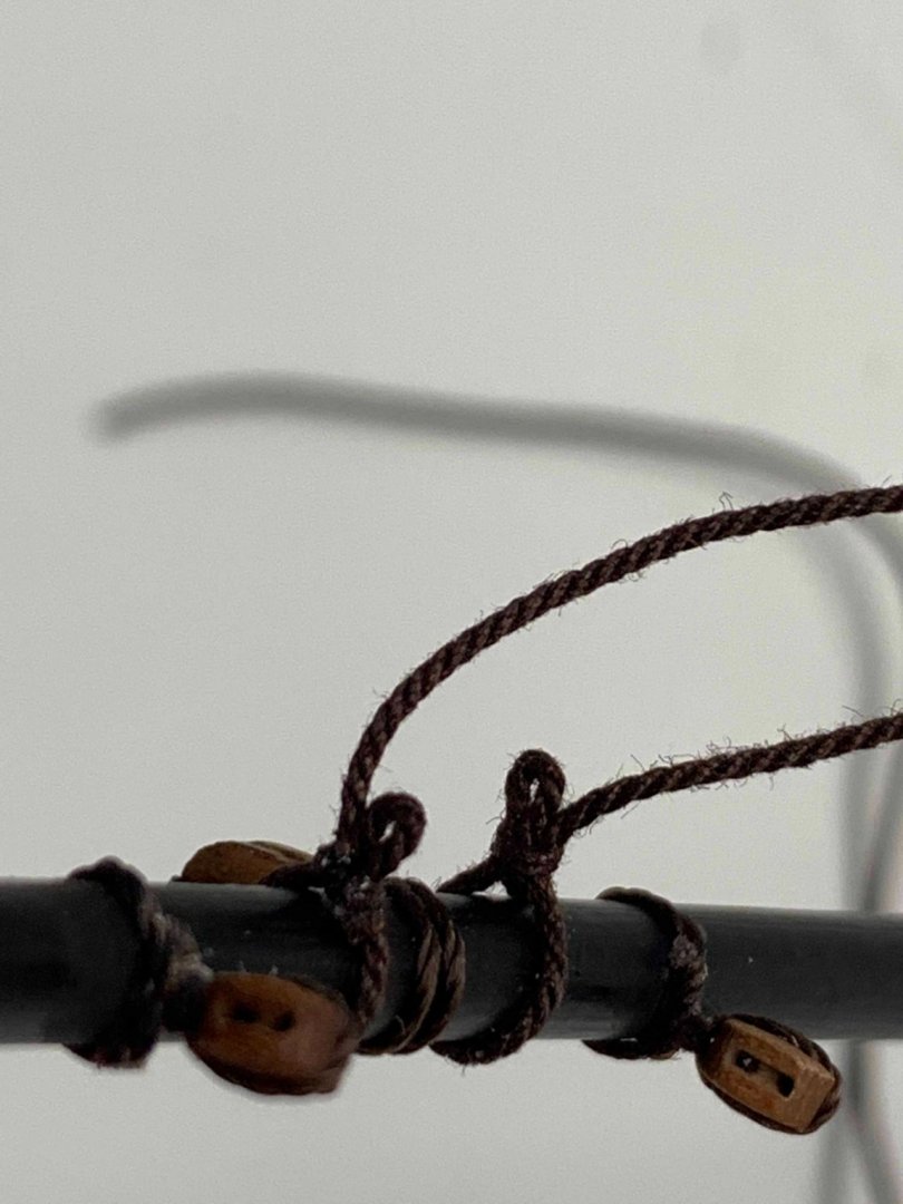
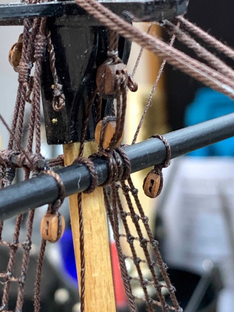
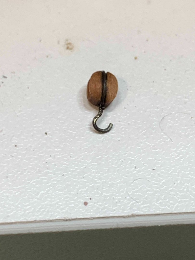
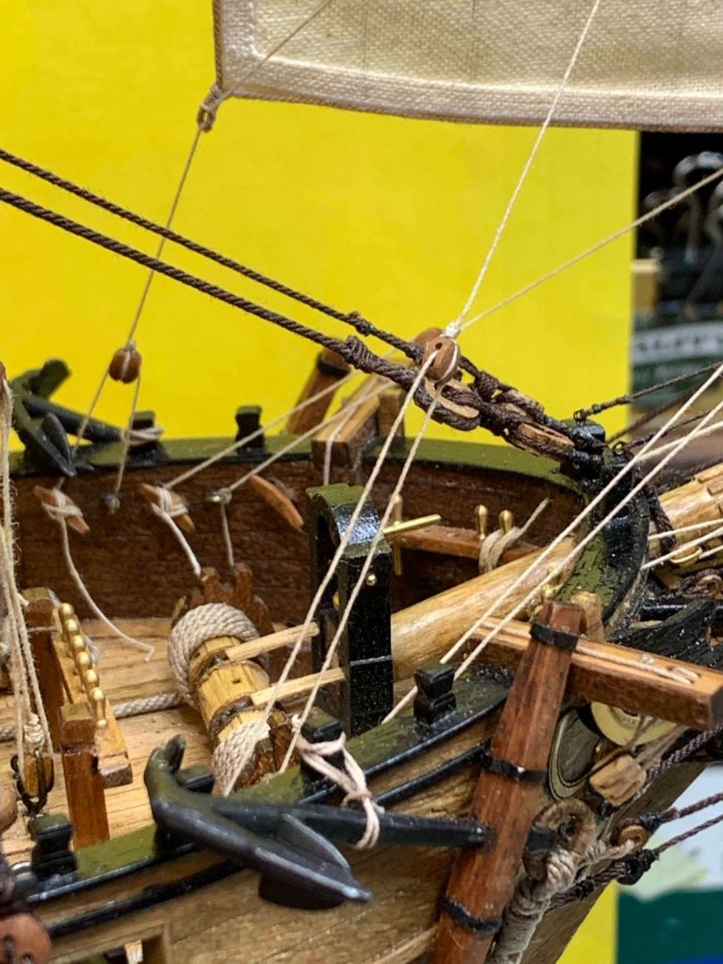
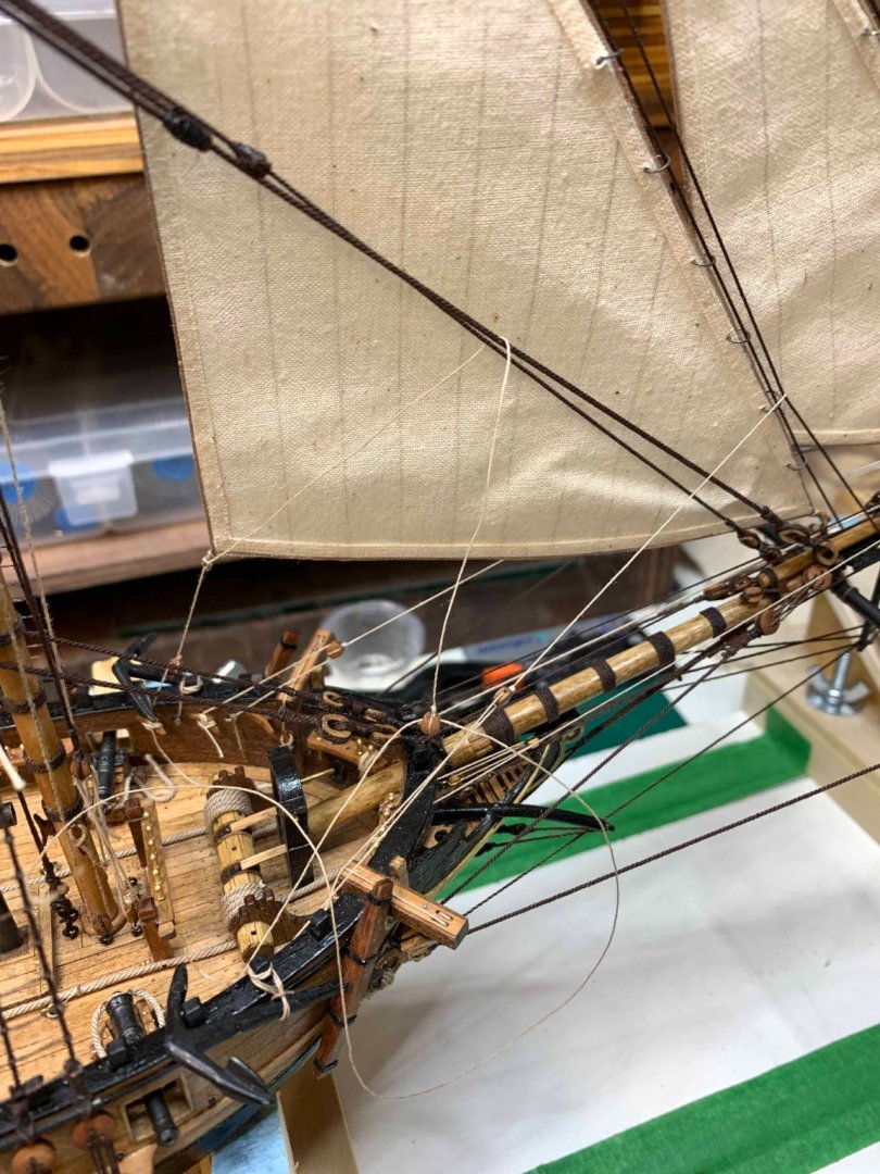
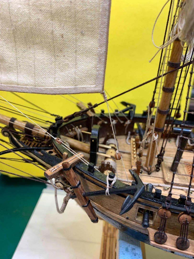
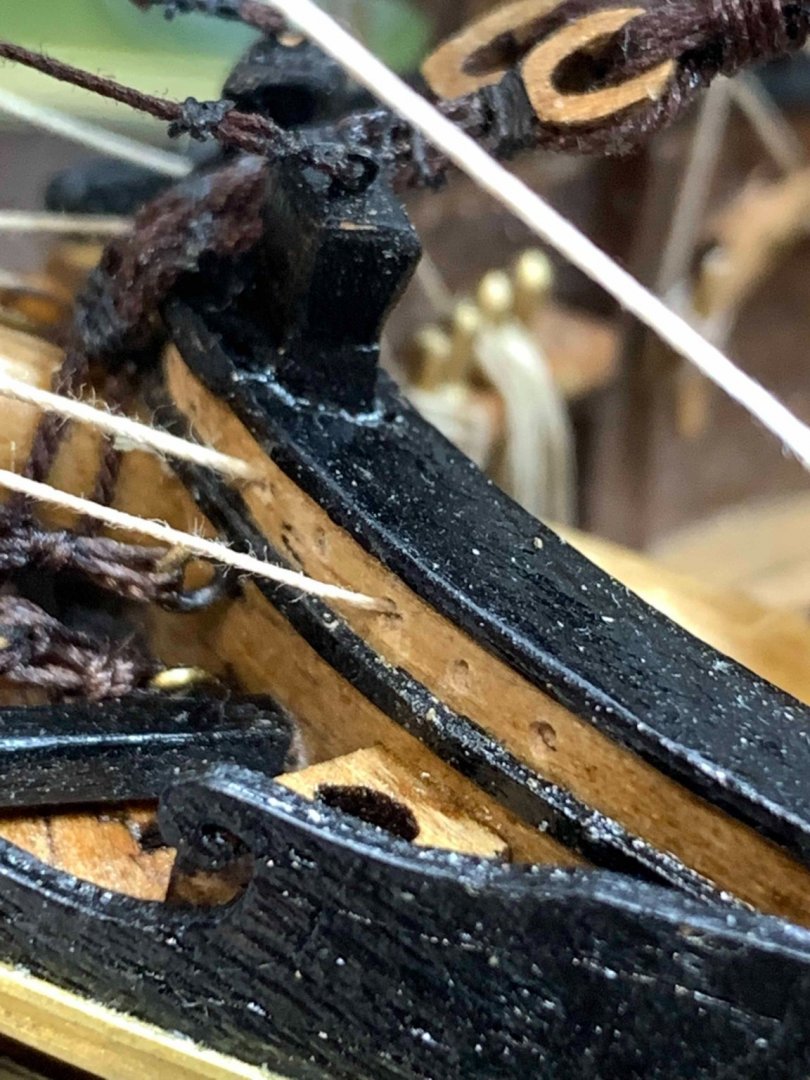
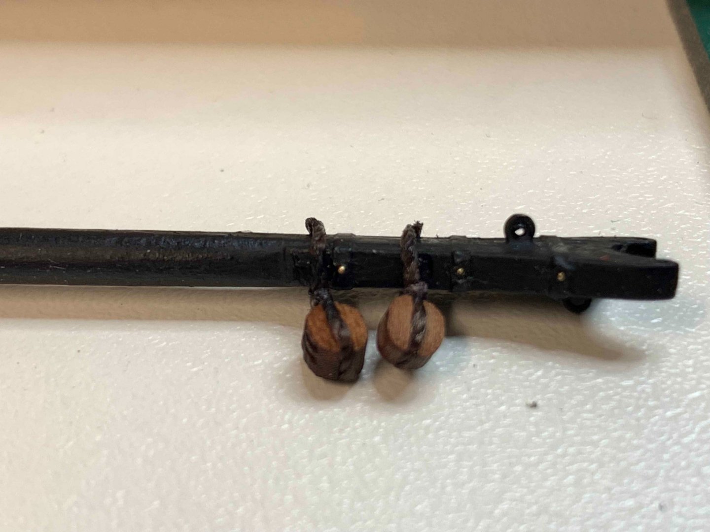
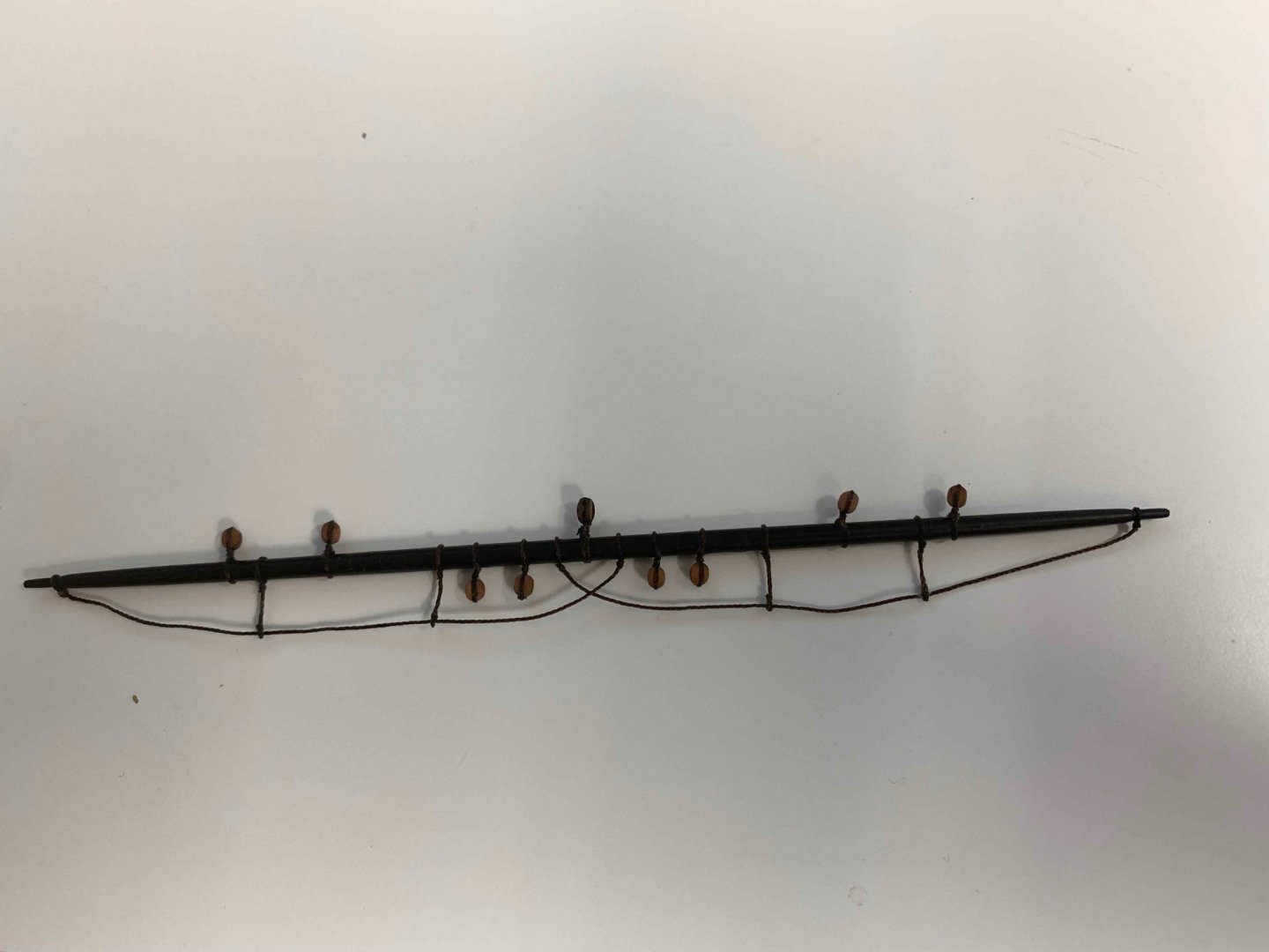
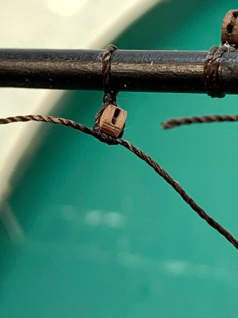
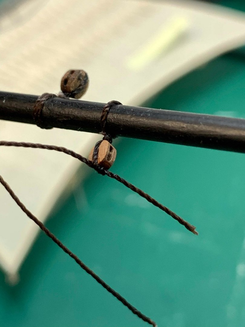
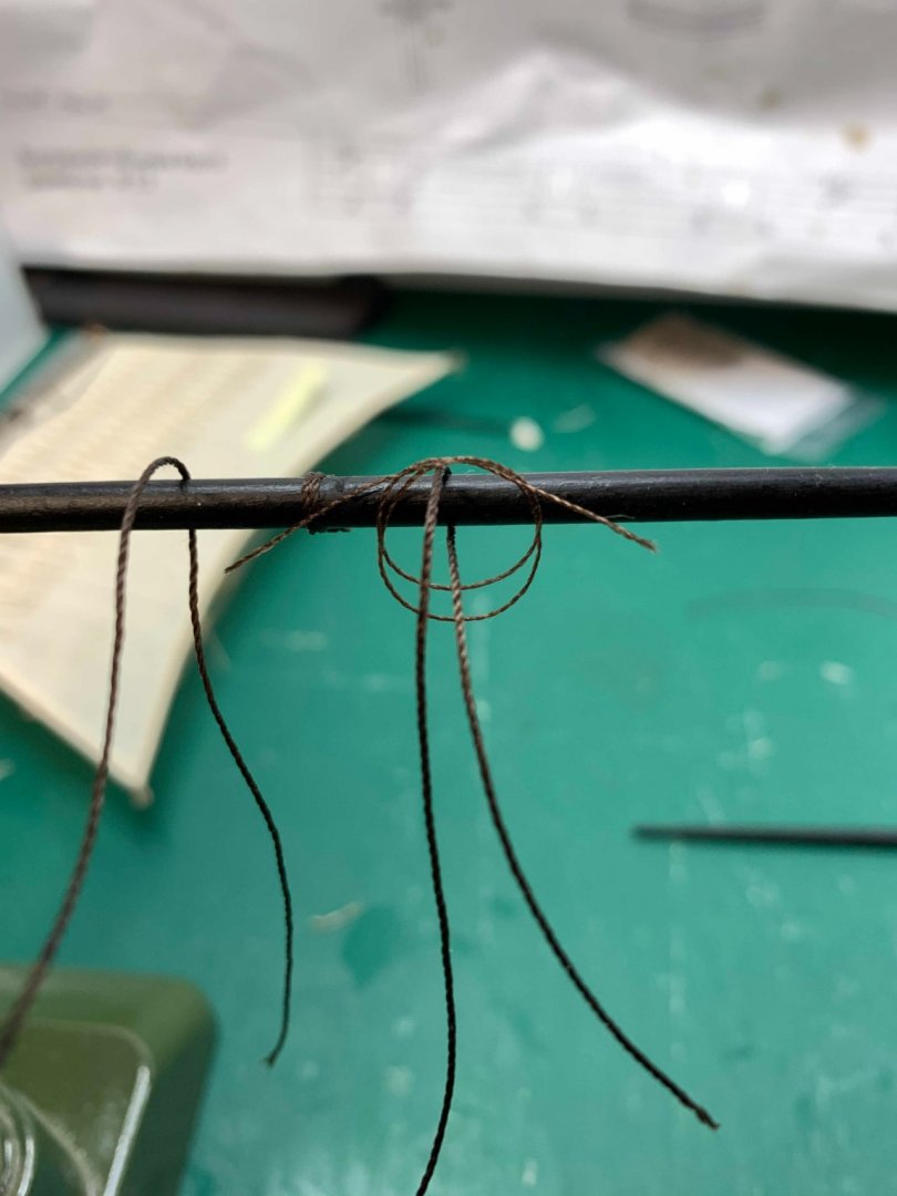
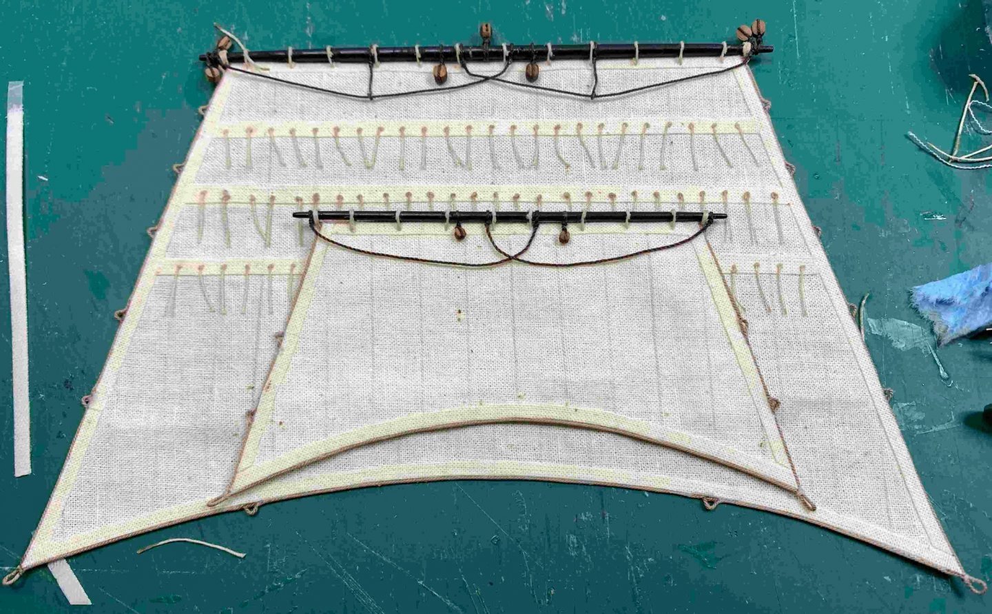
Making few blocks with a hook... first, wrapped a wire around the block, added a rope on the opposite end off the hook, twist the wire and make a hook. Then, siezing the rope and freeze it with a glue. The whole block was dropped in blackening solution. With seizing the rope and freeze it first, the blackening solution will no "blackened" the rope, because the glue will prevent solution going into the rope. It is not a bid deal if seizing is done after blackening, just rope has to be pulled a bit more so the blackened rope is removed... Rigging the sprit-sail yard is next. First, the block was rigged and attached to the yard.. ... the rope was pulled thru... Few more other ropes were attached... Getting crowded up here... ... and ended up on pin. I put a small amount of white glue to freeze the knot... when is dry, less visible than CA glue. Extra cord length will be cut off later.. Happy modelling...


- 275 replies
-
- 4
-
-
- phoenix
- master korabel
- (and 1 more)
-
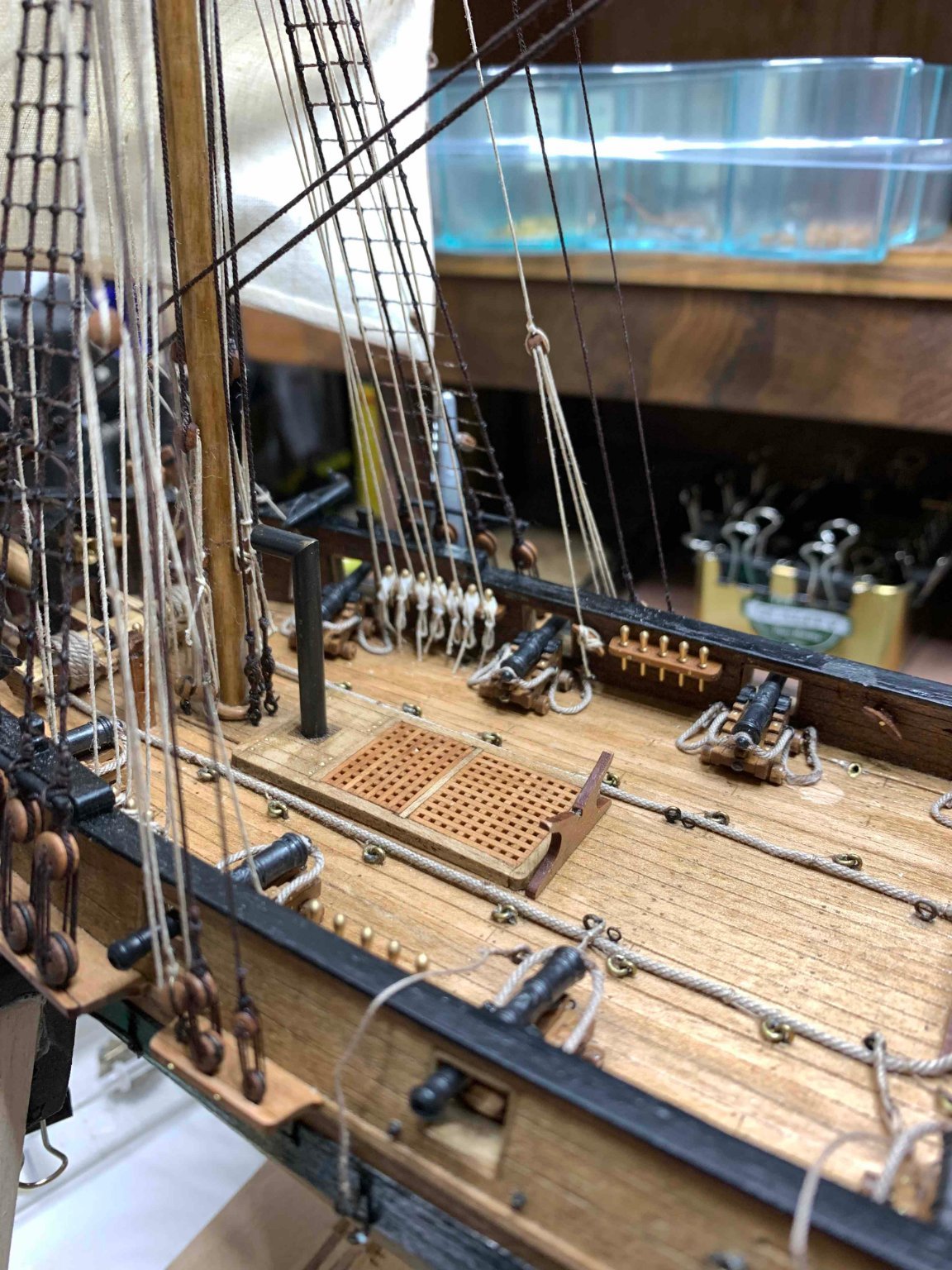
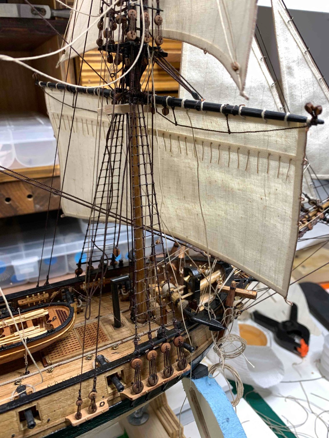
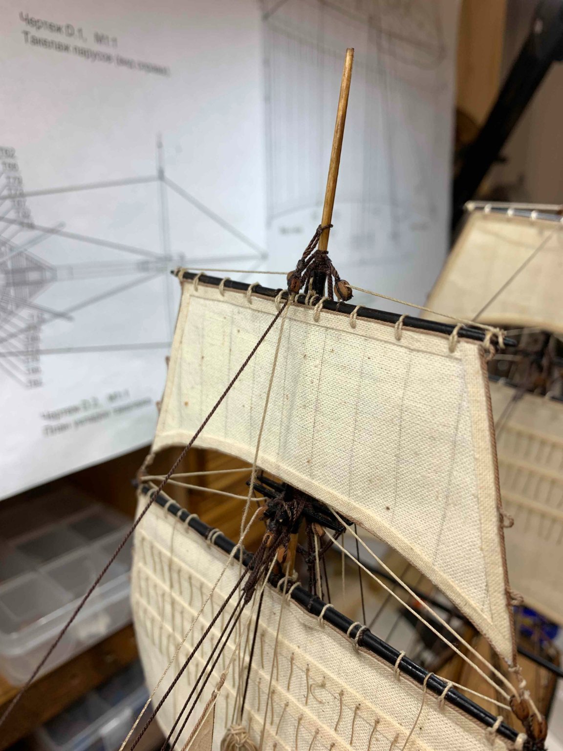
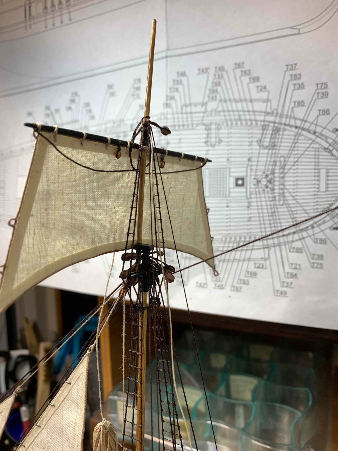
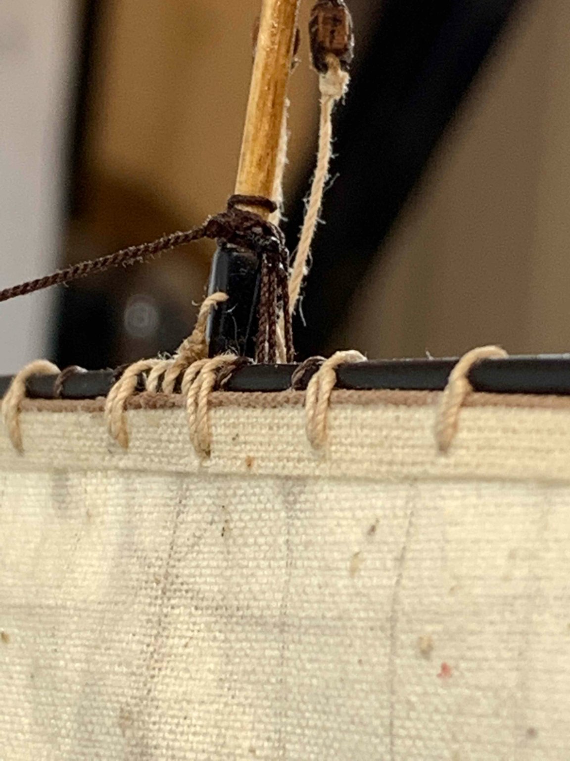
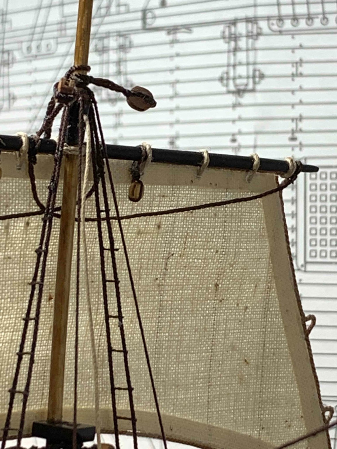
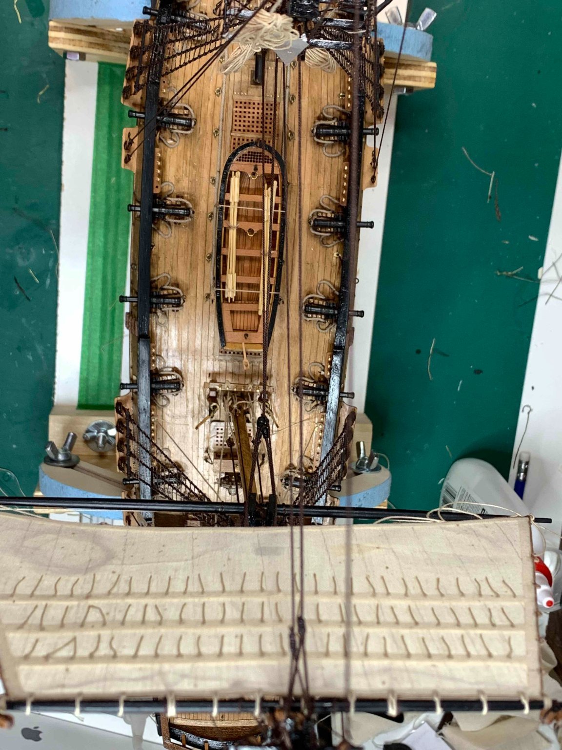
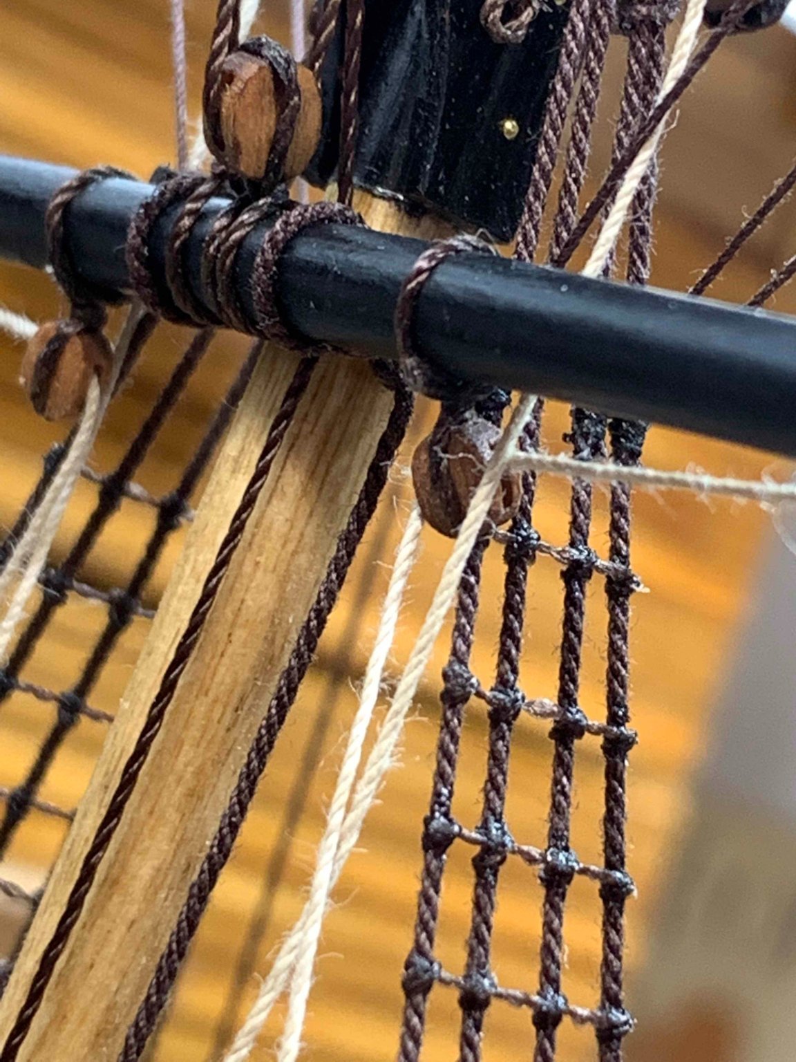
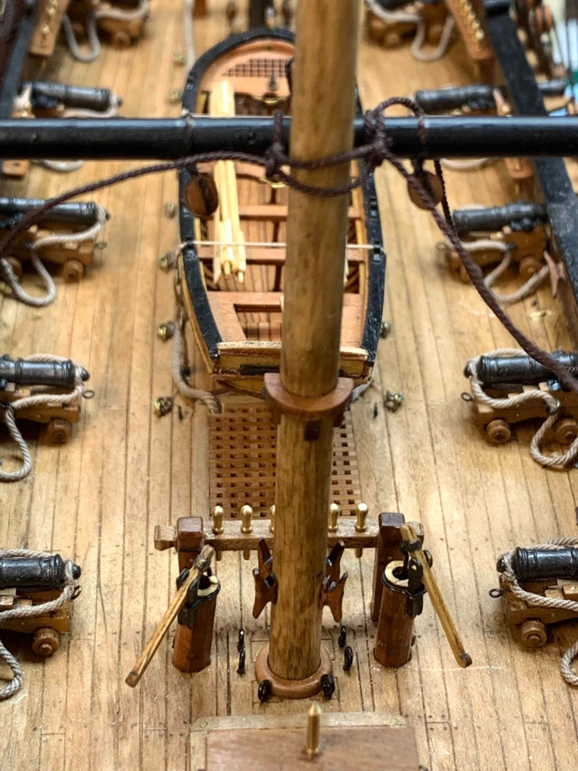
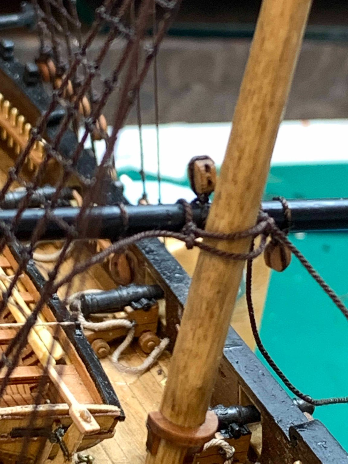
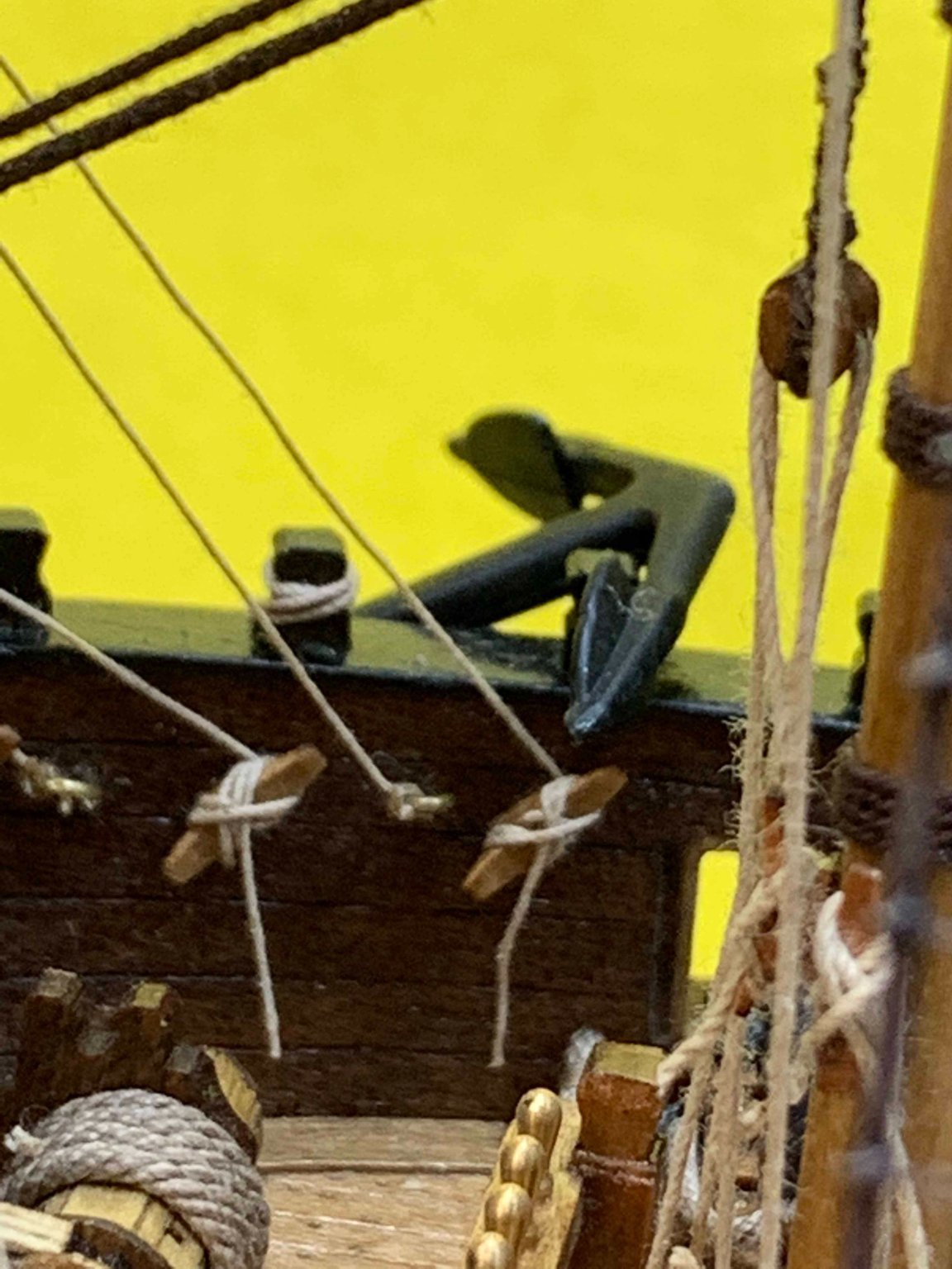
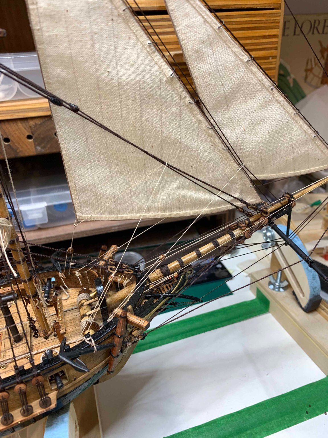
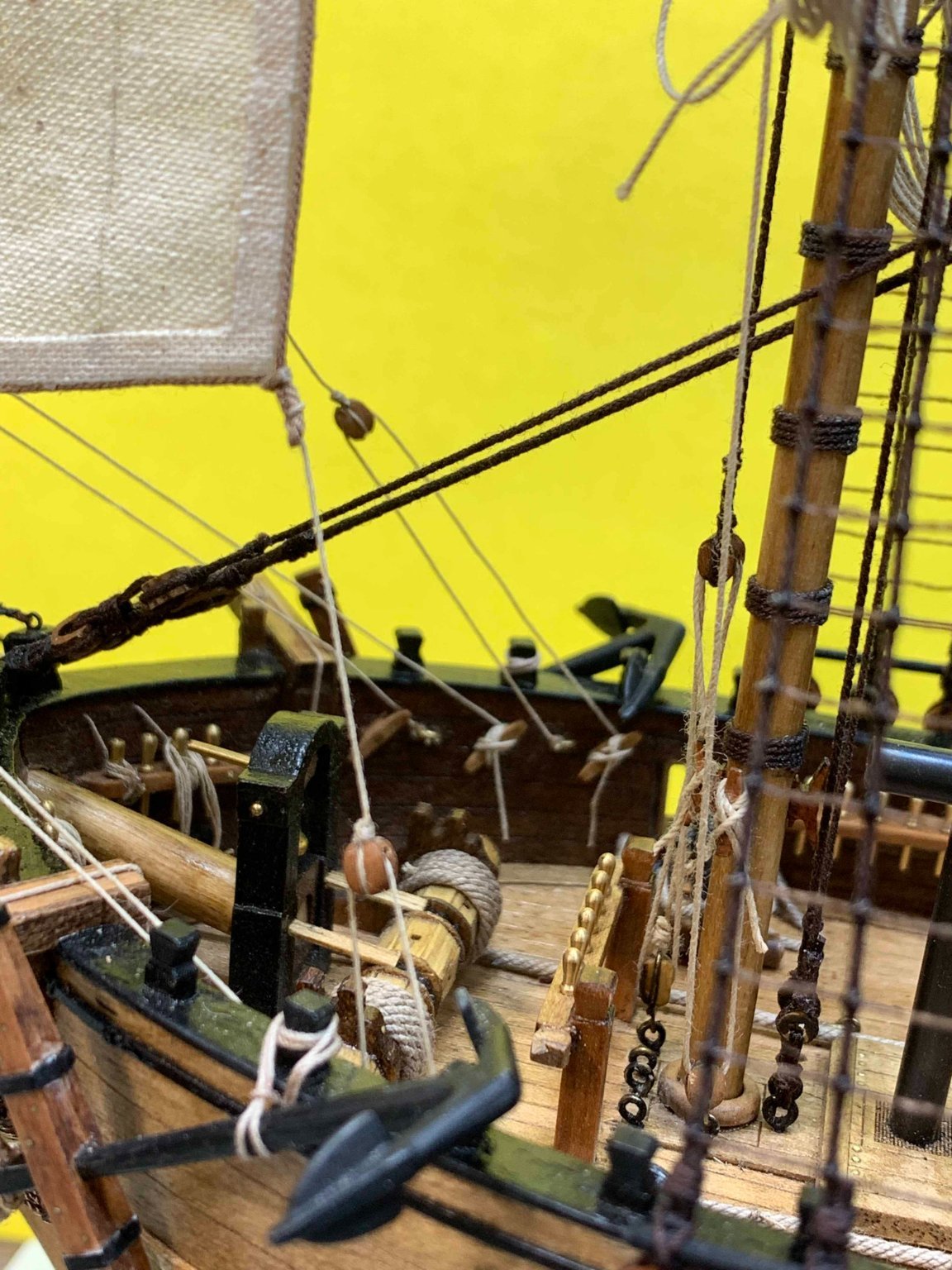
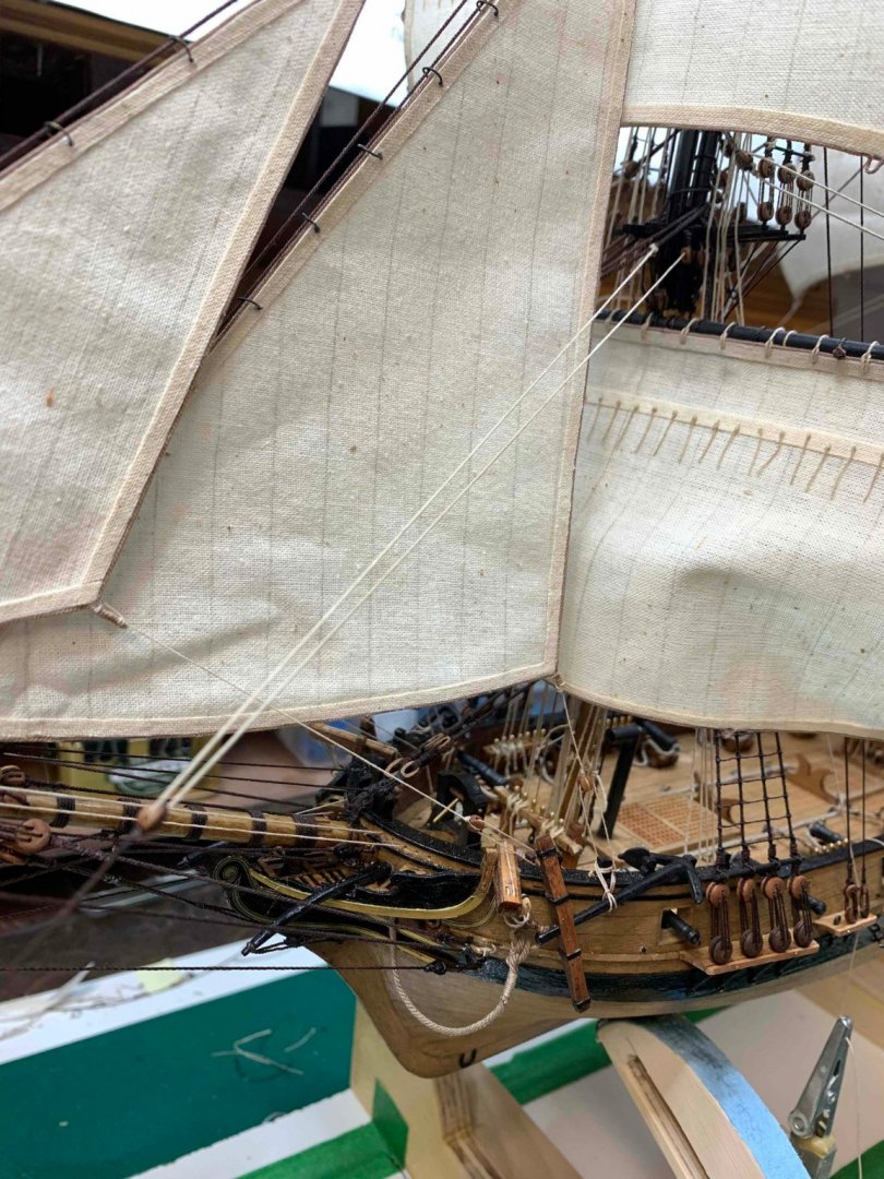
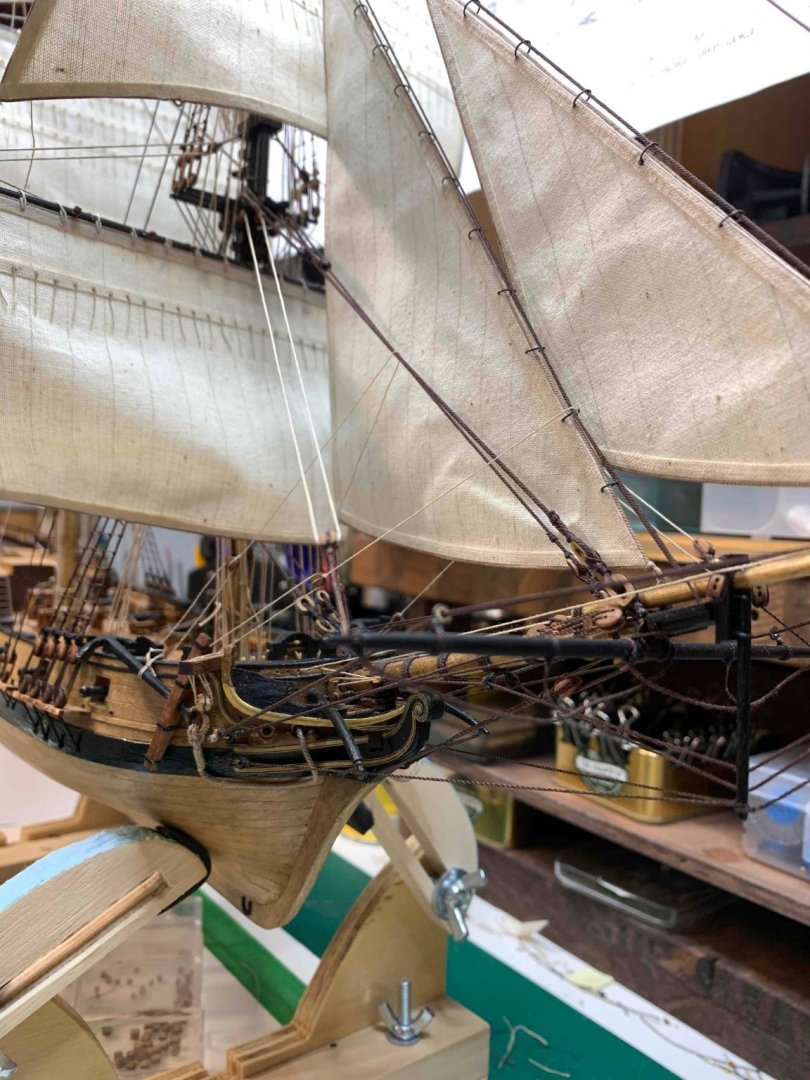
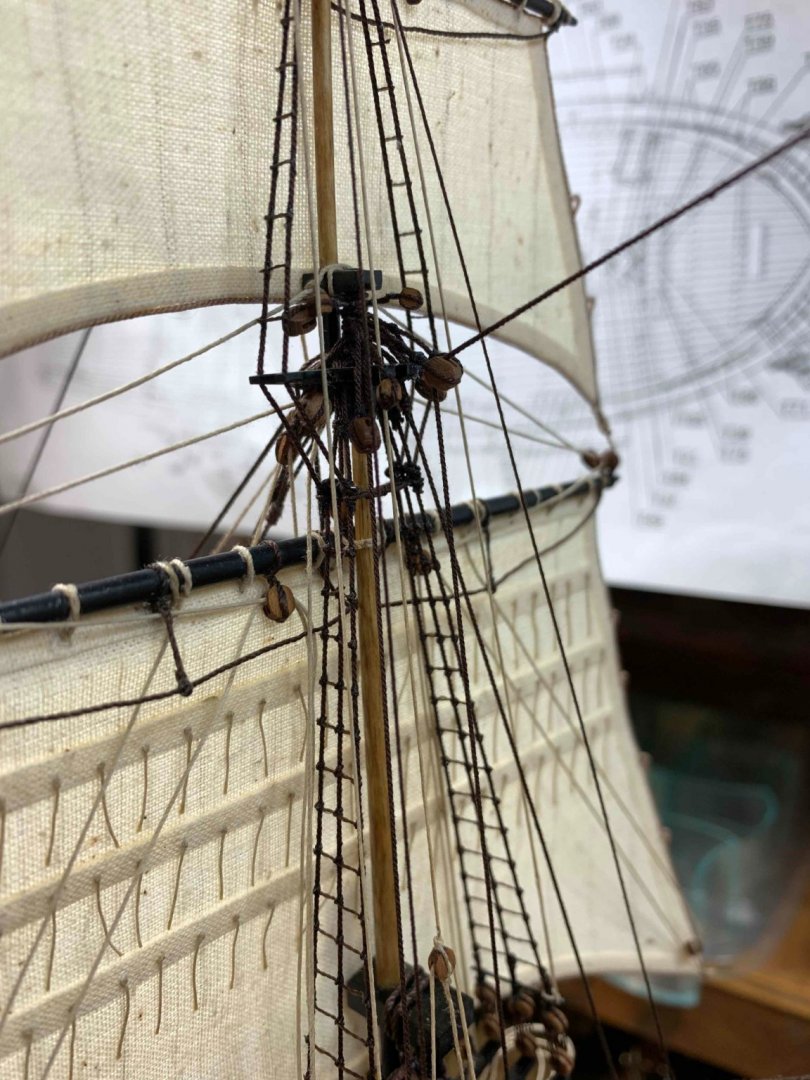
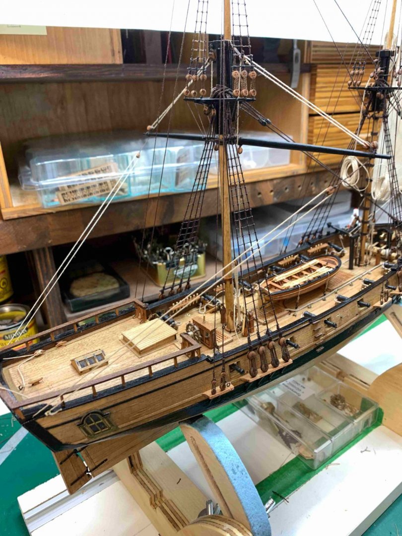
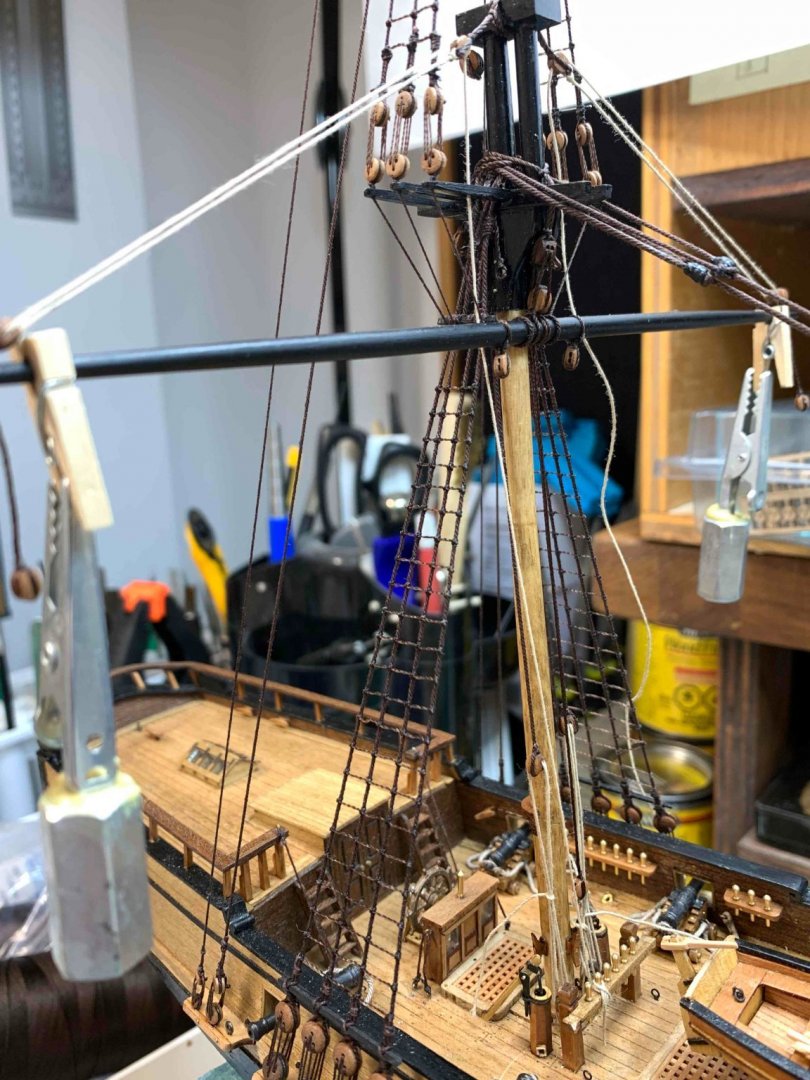
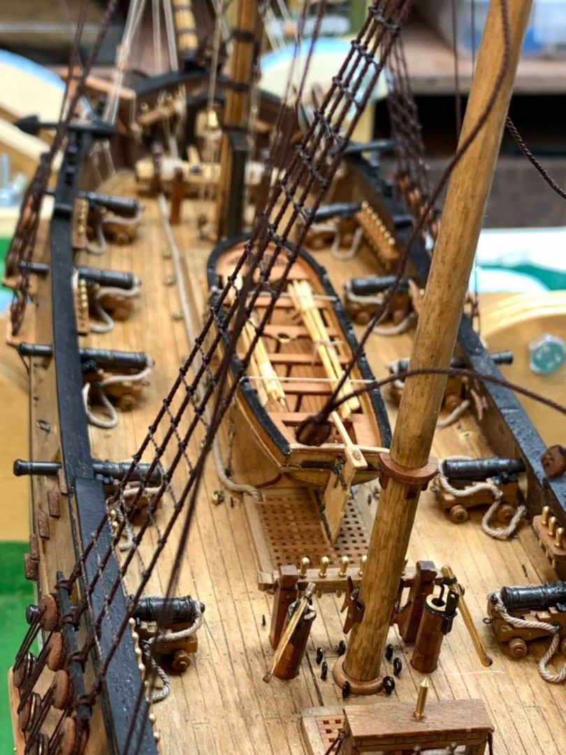
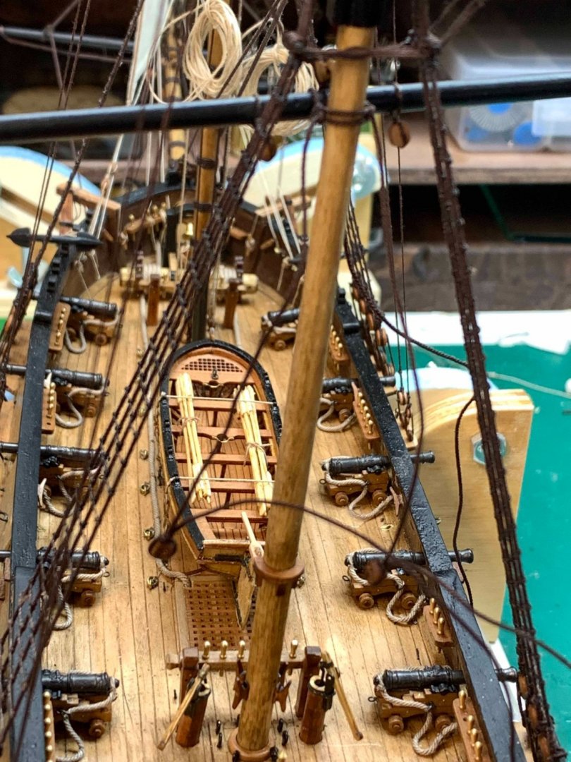
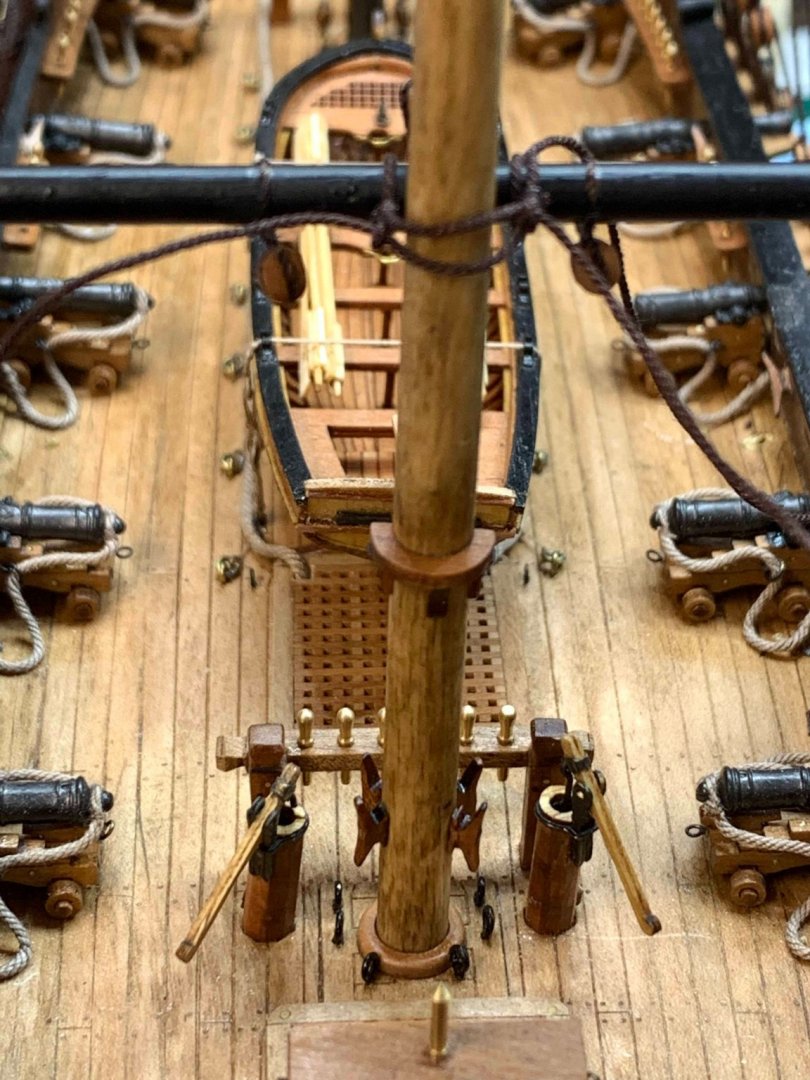
Few more progress work pictures.... Happy modelling...


- 275 replies
-
- 3
-
-
- phoenix
- master korabel
- (and 1 more)
-
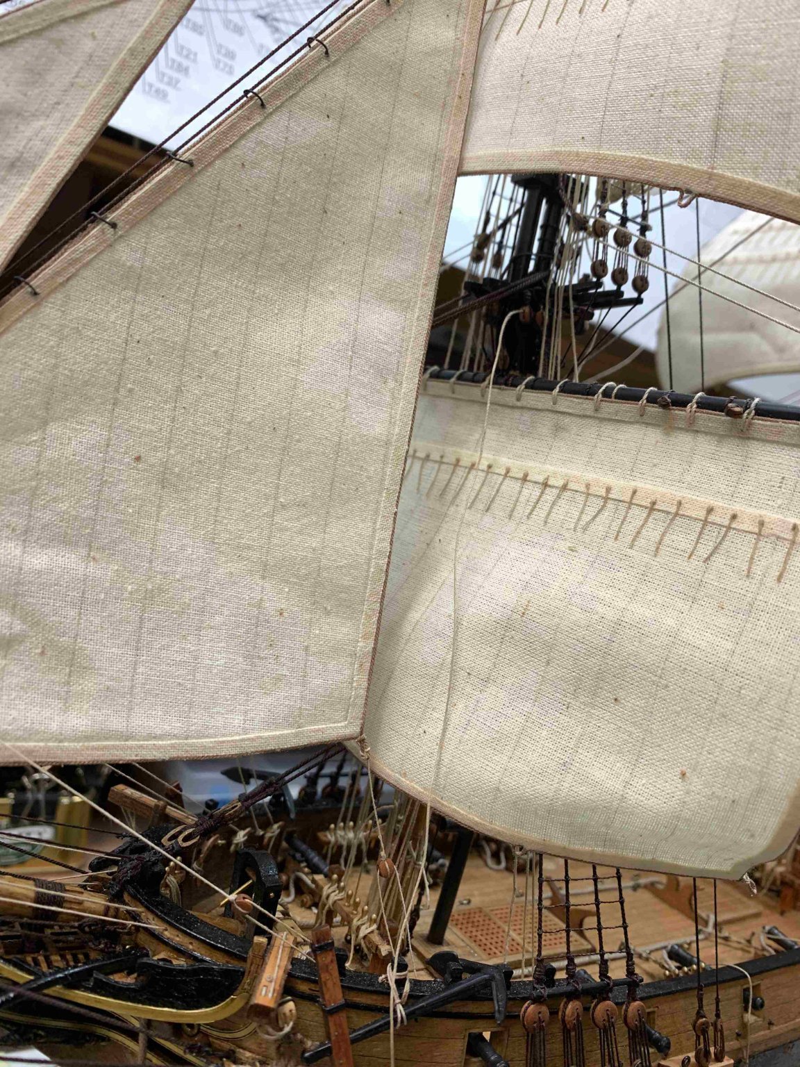
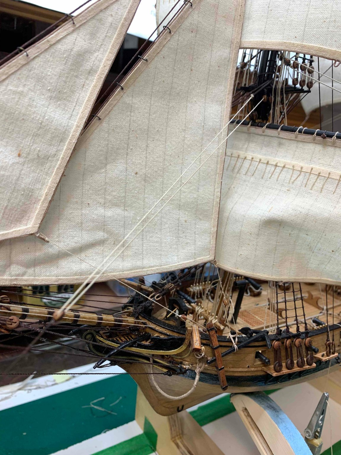
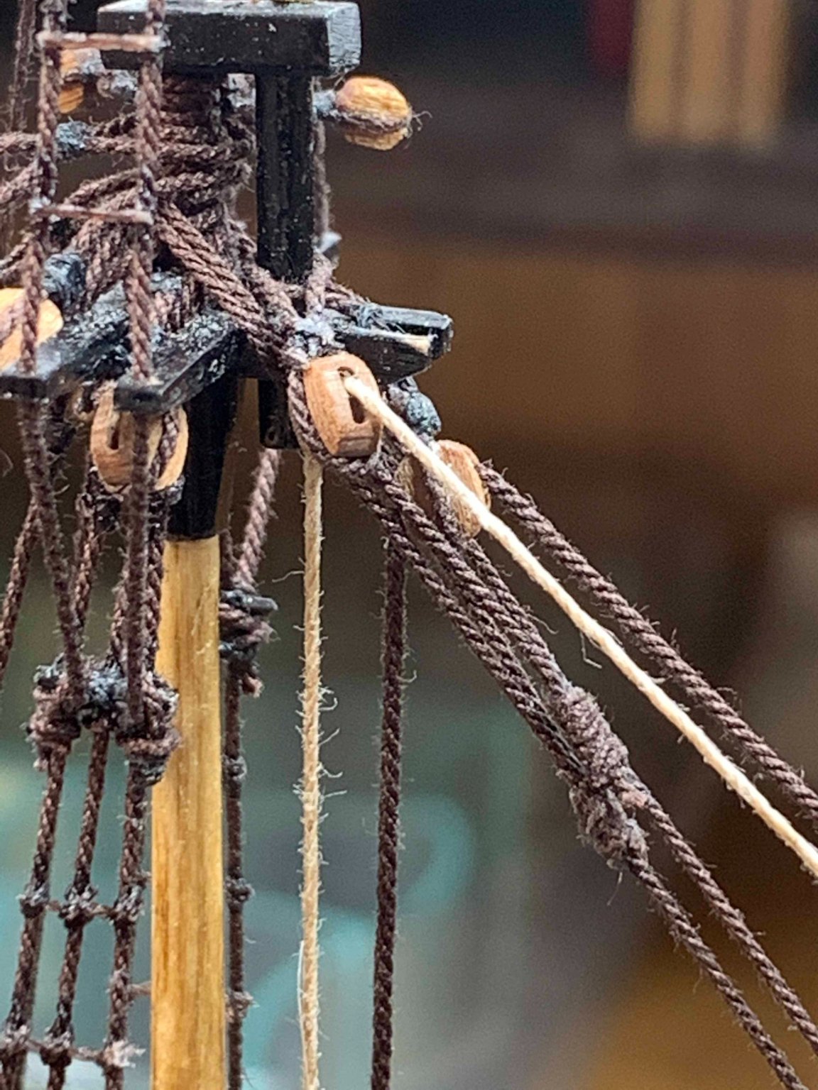
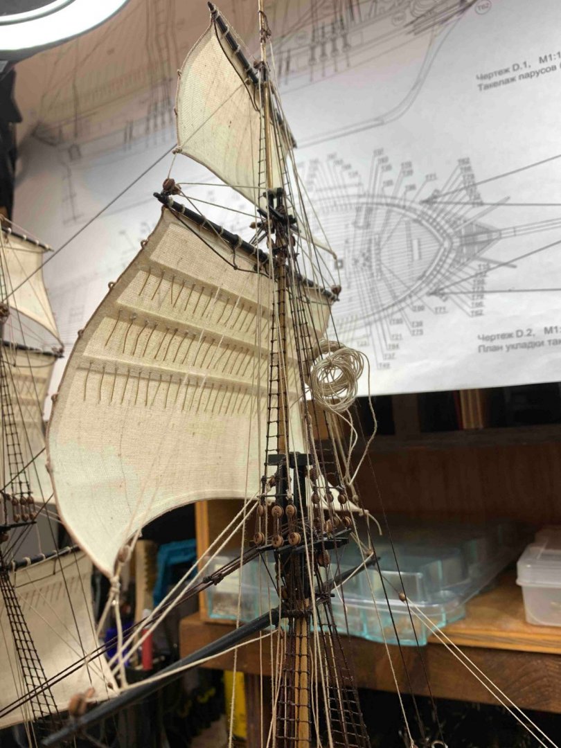
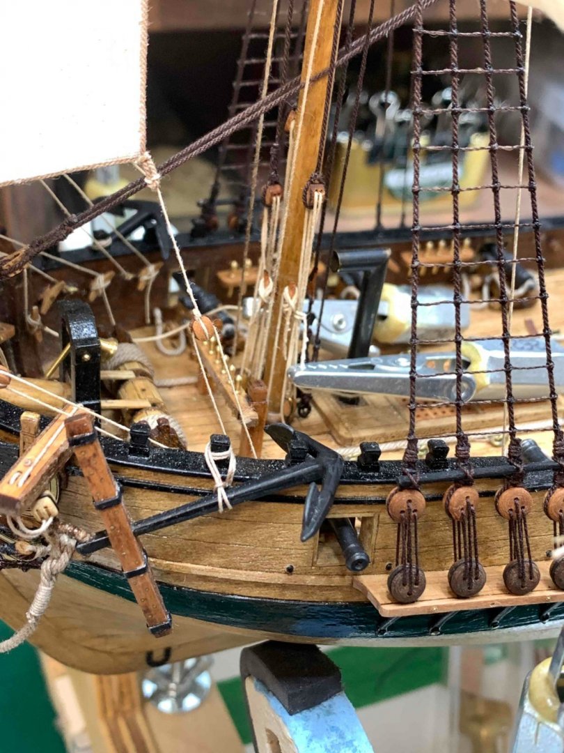
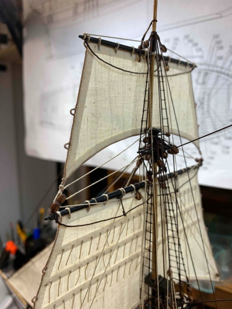
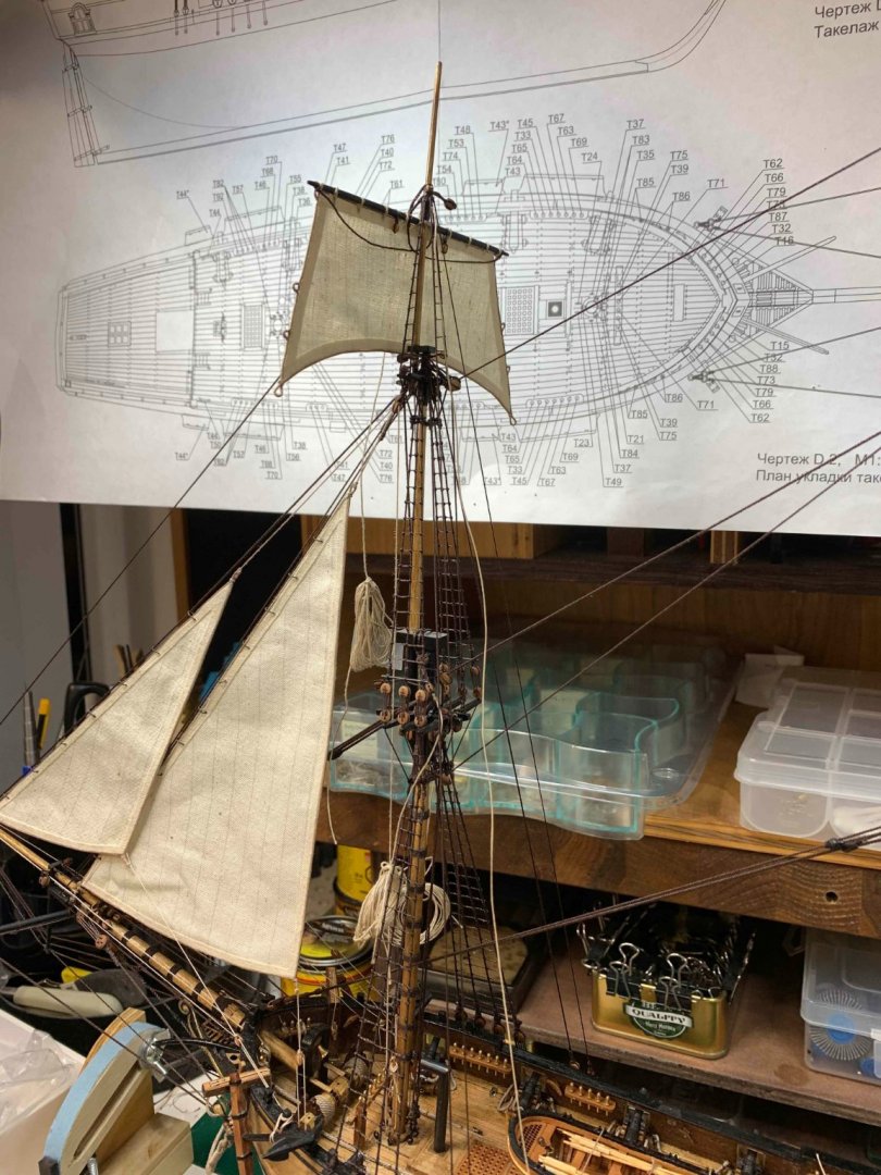
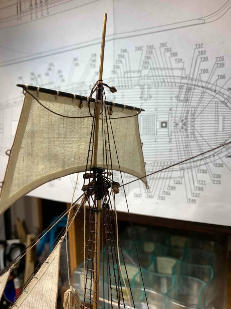
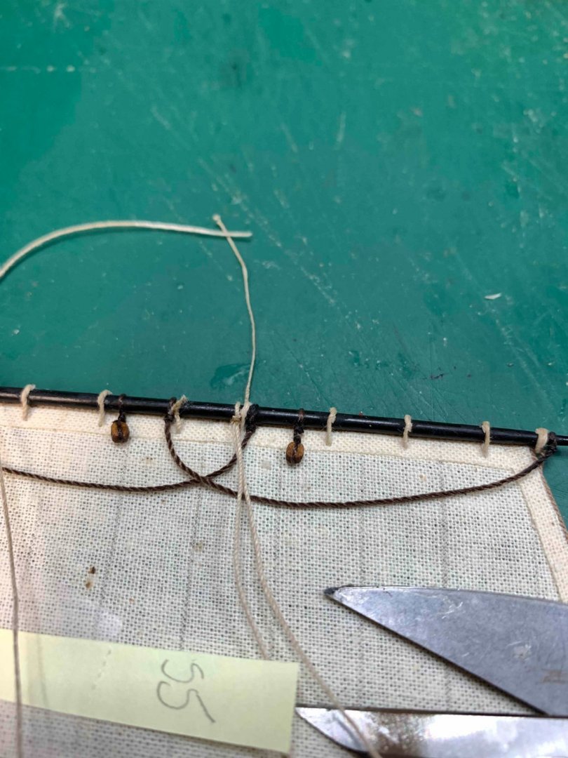
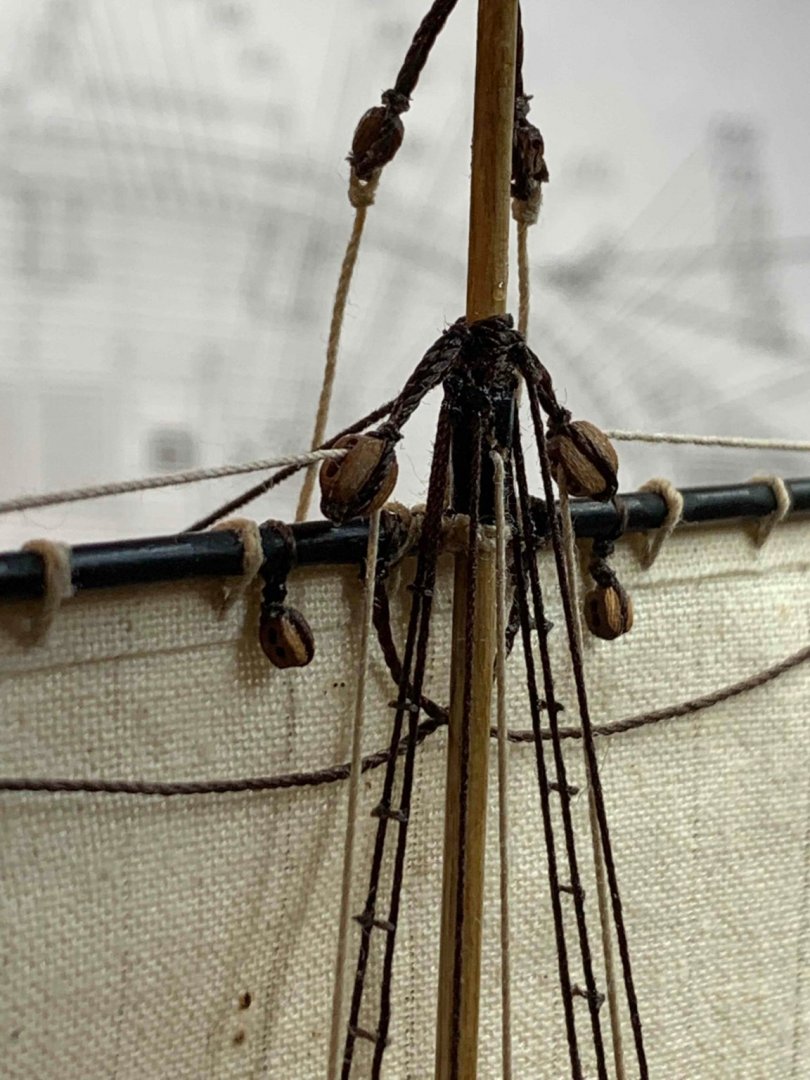
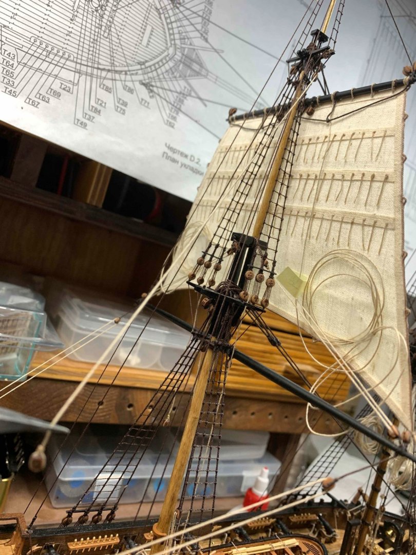
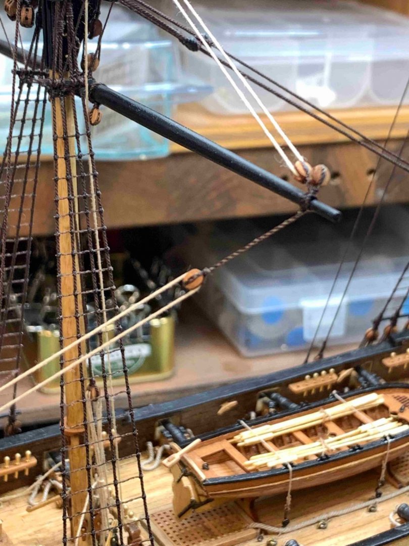
Rigging work continues, few random pictures... Happy modelling..

- 275 replies
-
- 4
-
-
- phoenix
- master korabel
- (and 1 more)
-
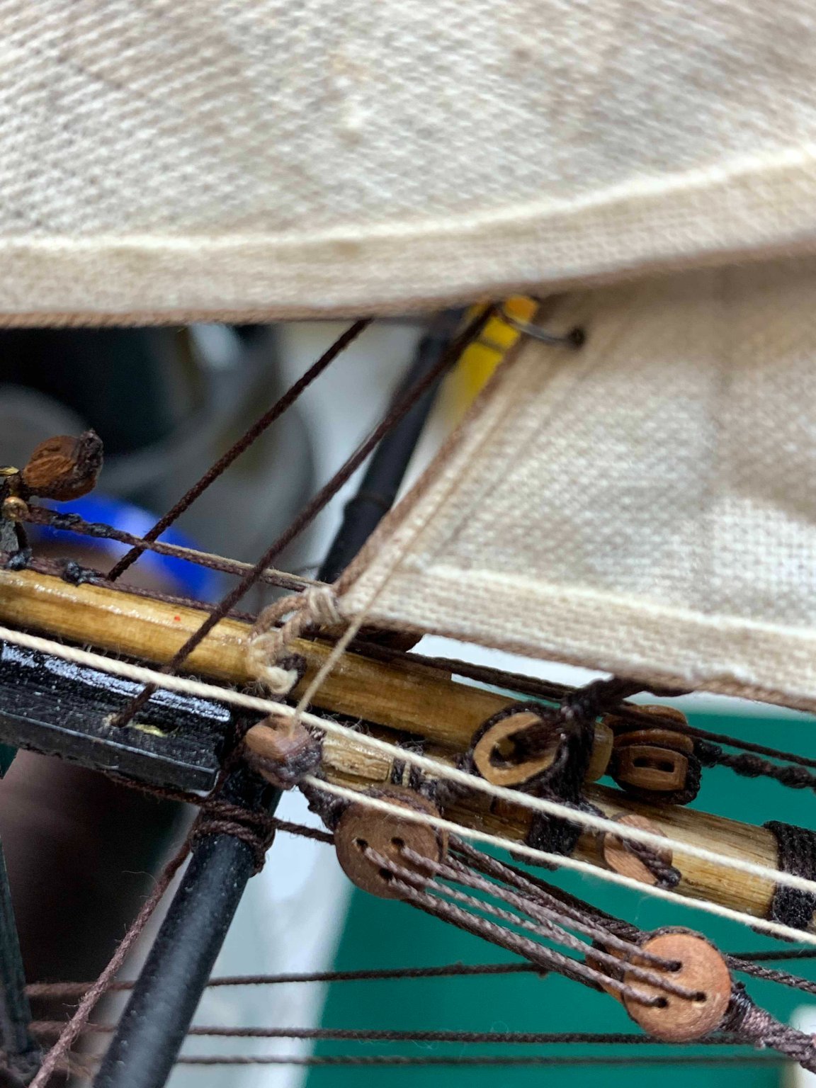
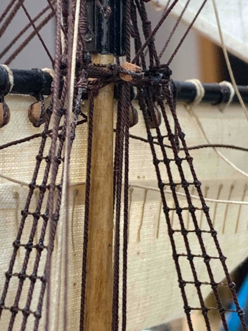
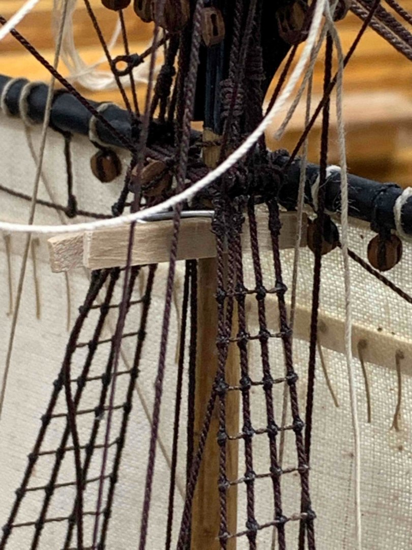
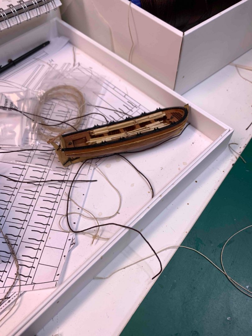
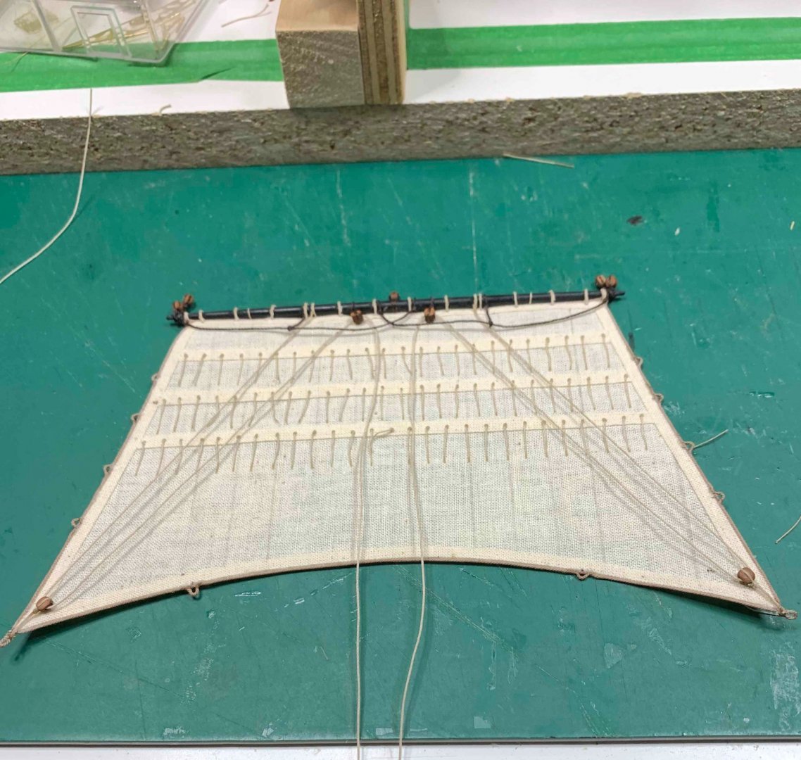
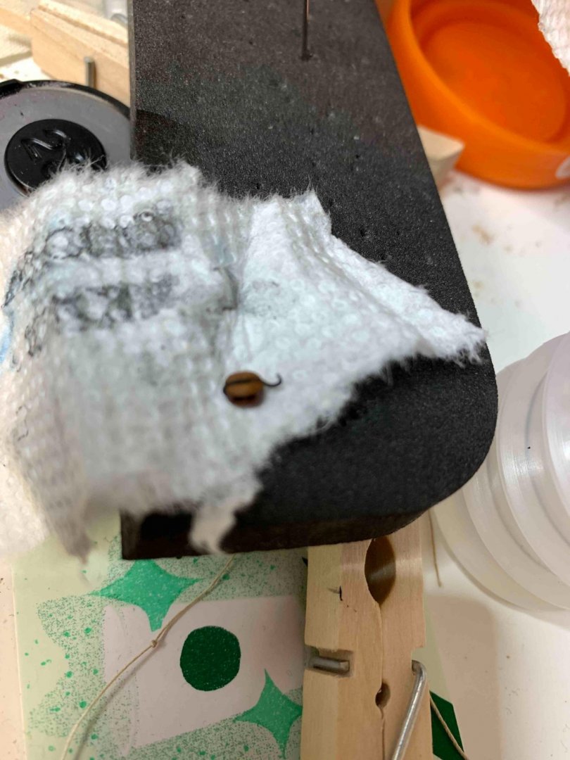
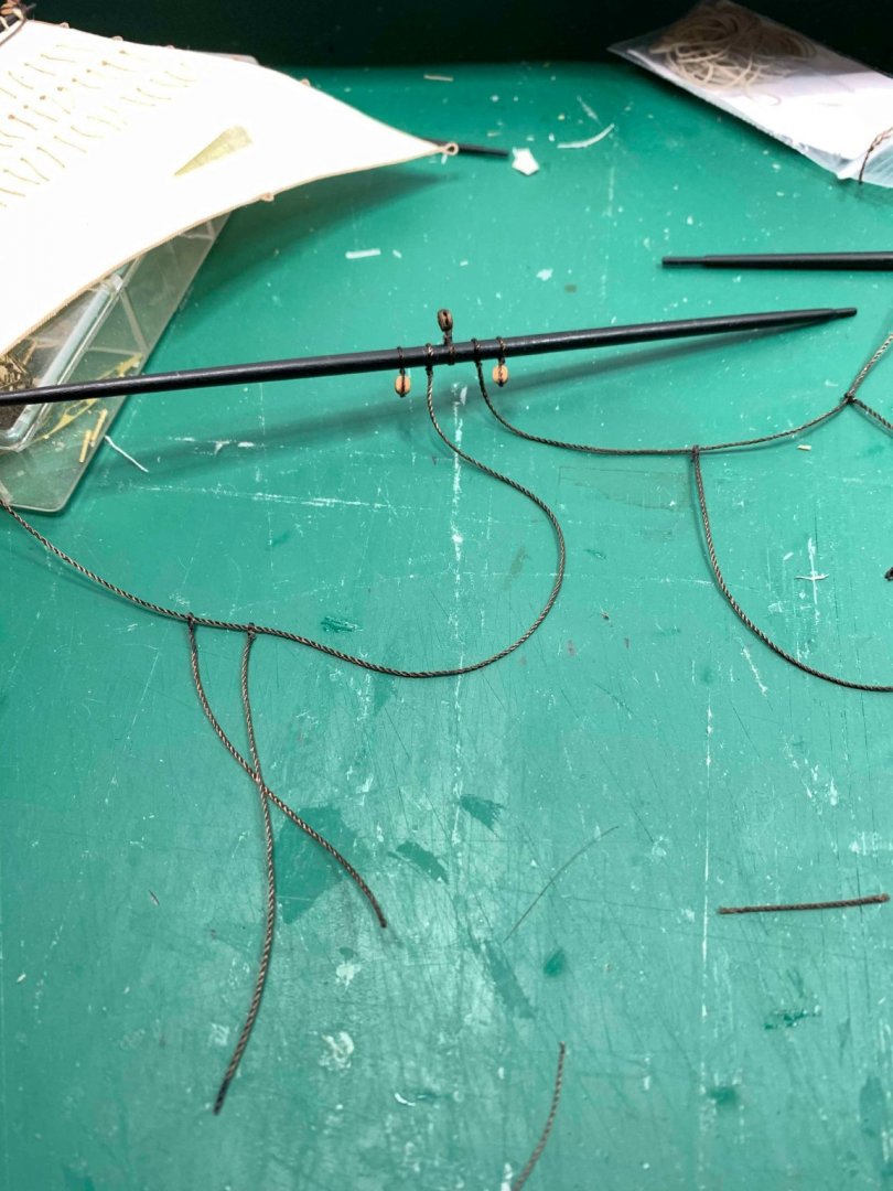
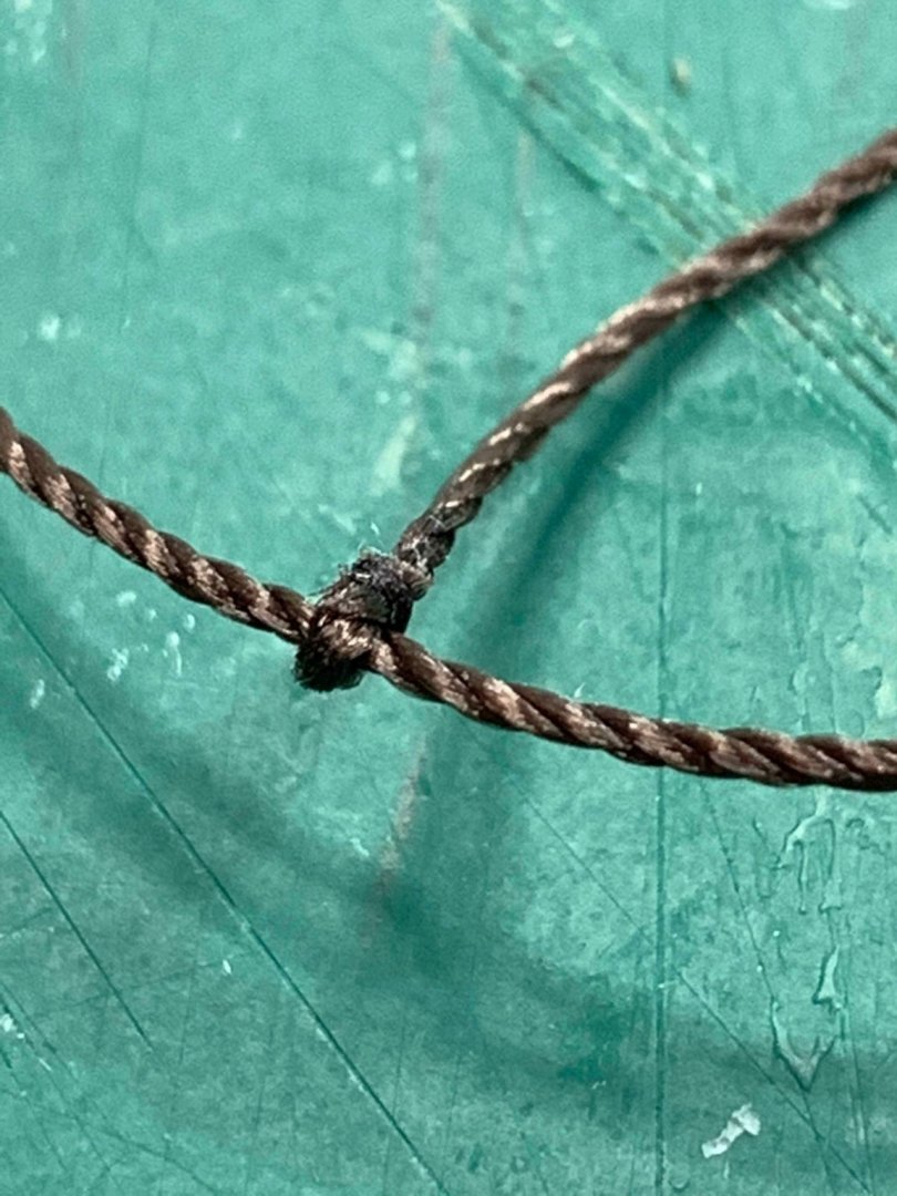
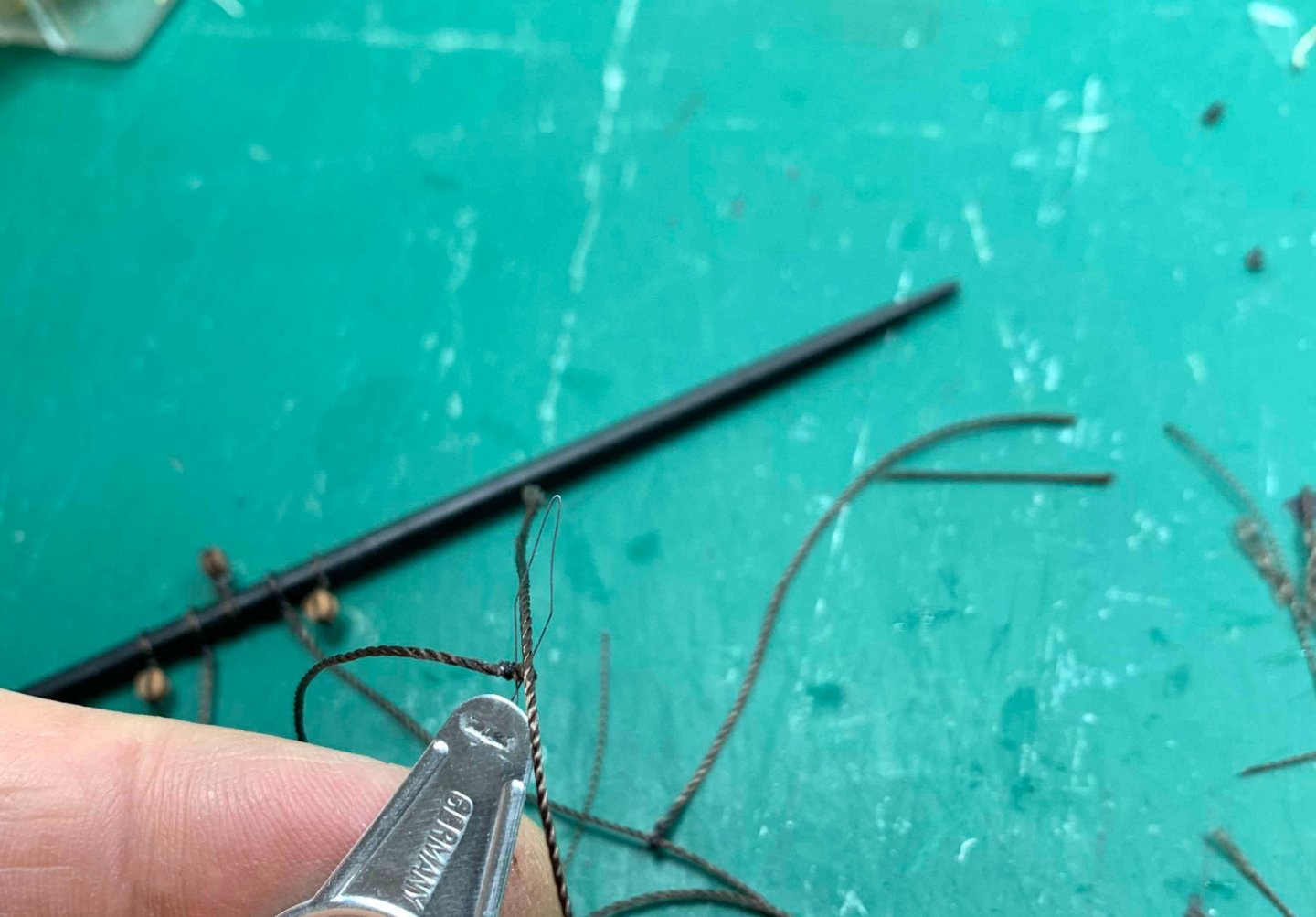
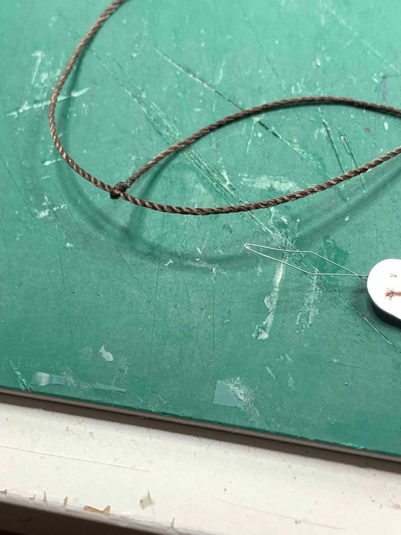
During the work, one line was damaged and needed replacement.. It was replaced and all is good again... I also removed the ship boat as i will be adding few more details to it... Which in turn, leaves a bit more space for work.. Another parral to build... And continue with the sail... keeping it up with a small cloth pin... Then i had to rearrange and reposition some ropes correctly.. a bit of diluted white glue to keep the ends straight and some weight till glue dries... Happy modelling..


- 275 replies
-
- 3
-
-
- phoenix
- master korabel
- (and 1 more)
-
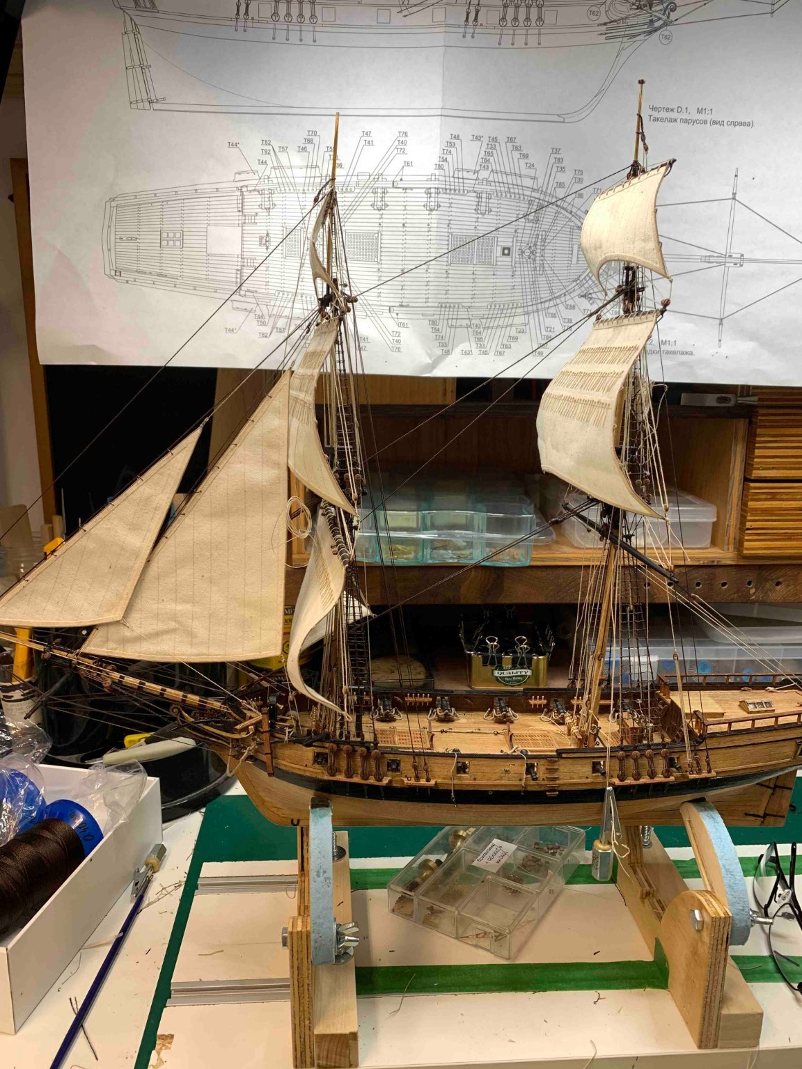
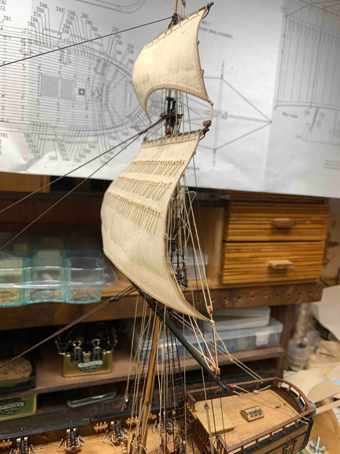
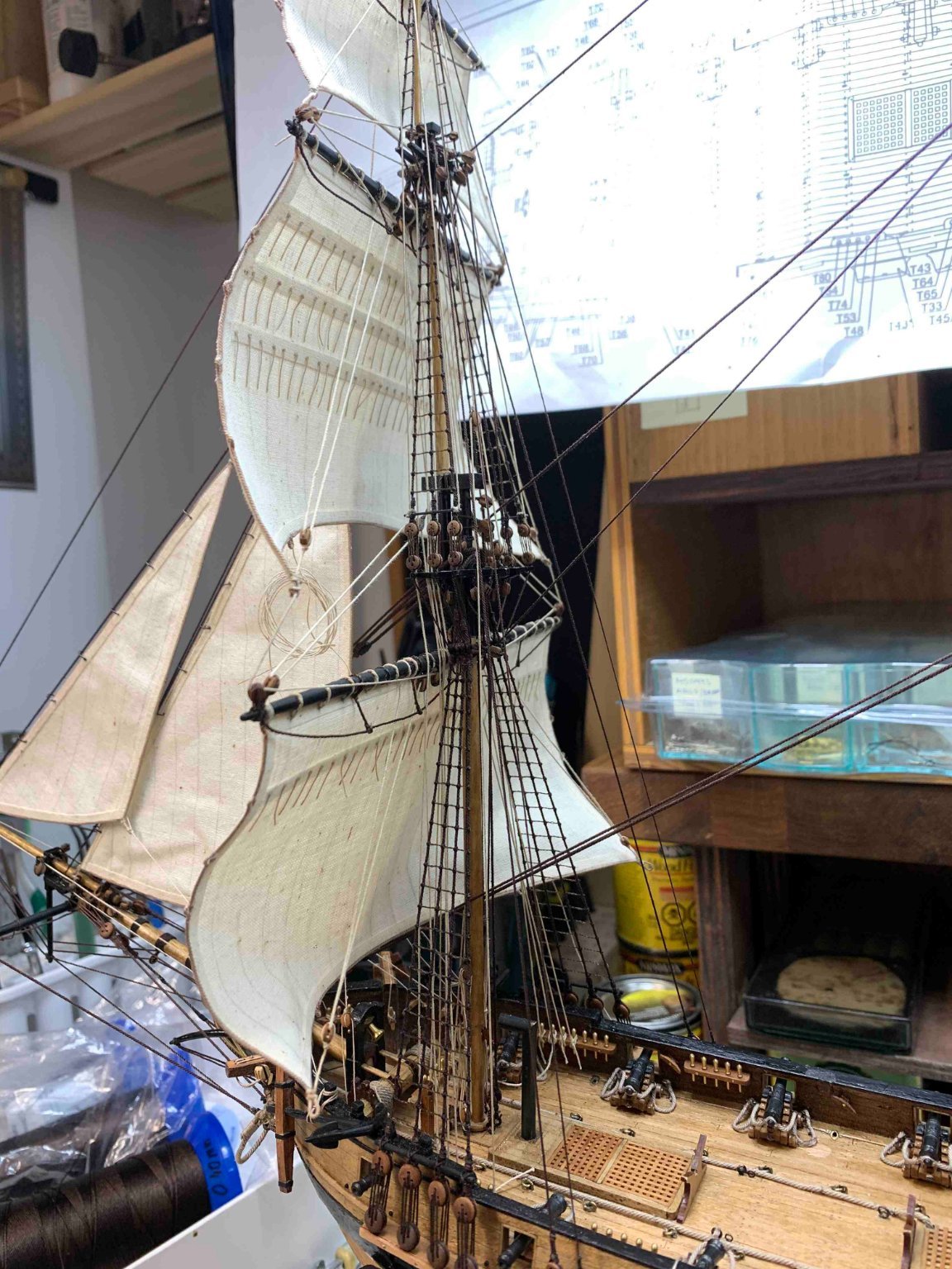
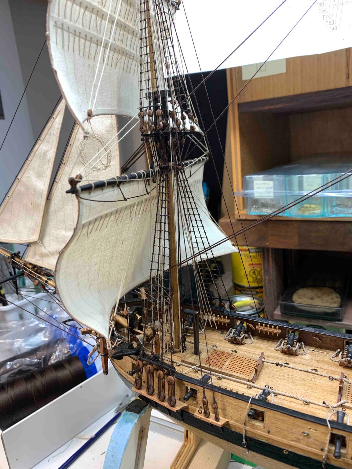
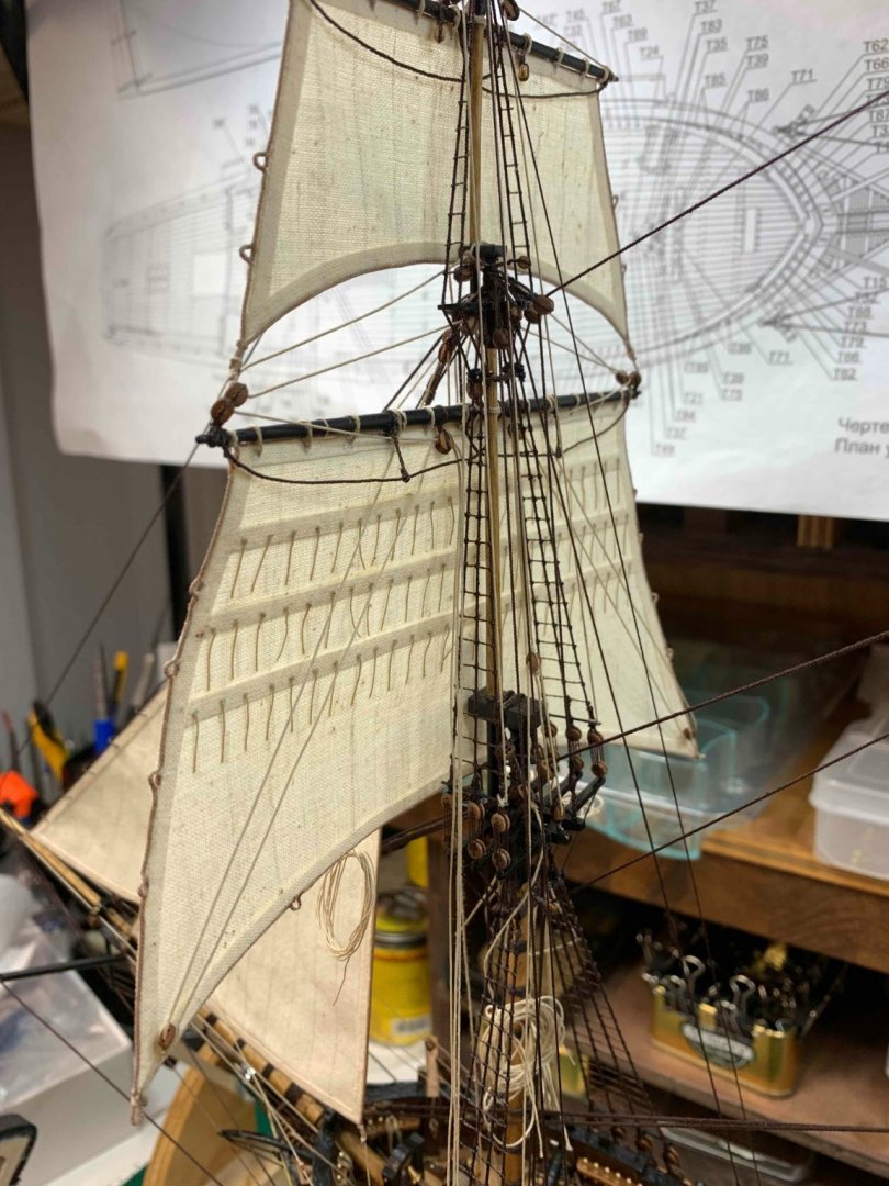
Ready to go up. Some rigging work in no particular order... Happy modelling..


- 275 replies
-
- 3
-
-
- phoenix
- master korabel
- (and 1 more)
-
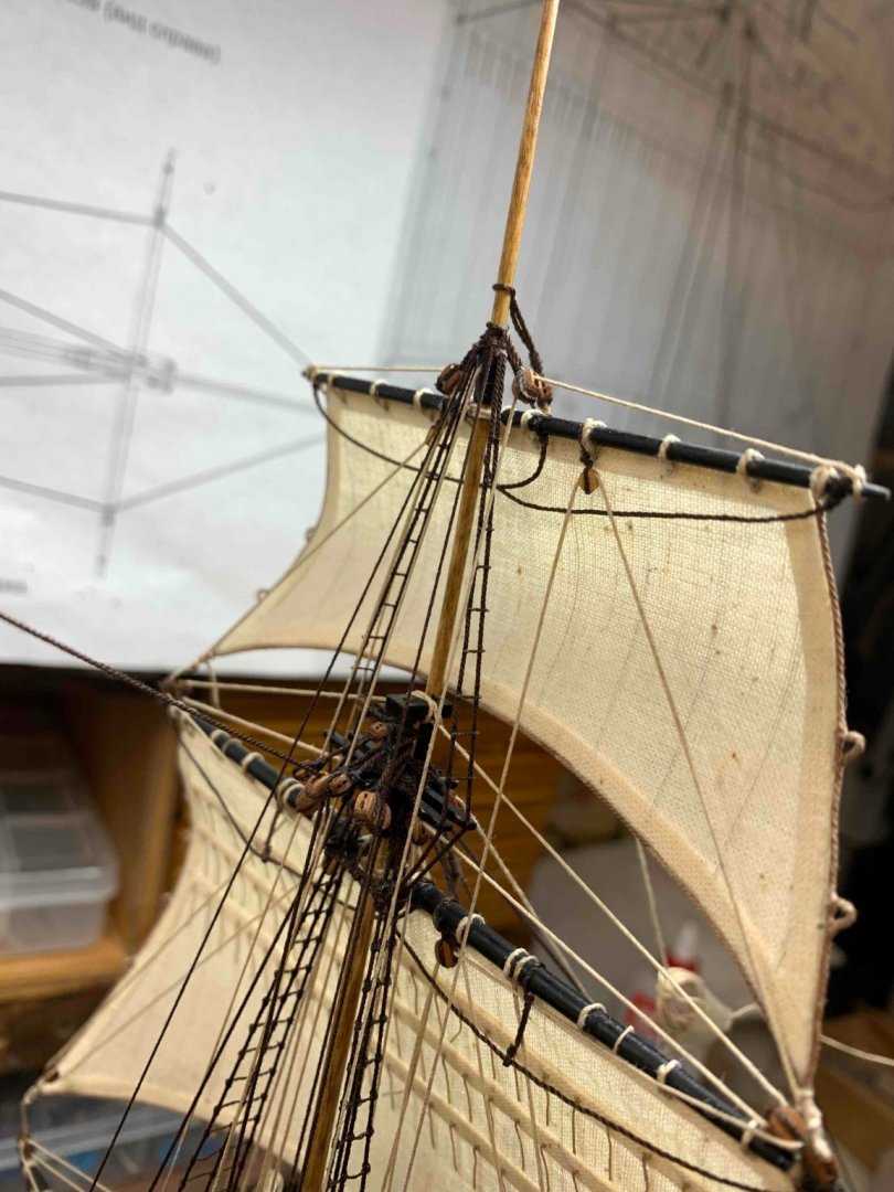
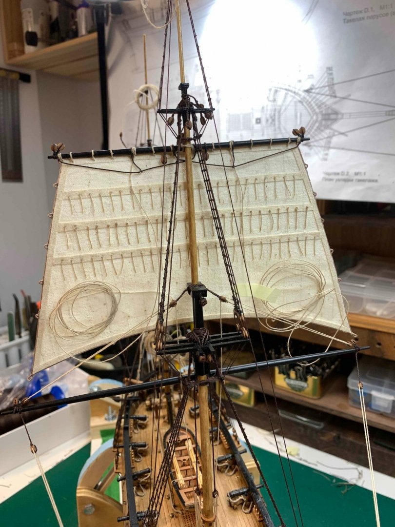
Getting rigging ready for a main-topgallant sail.. During process of attaching the sail, the block rigging just snapped, so needed to make another one... to bad the line was already on the sail.. Making parral.. Happy modelling..


- 275 replies
-
- 3
-
-
- phoenix
- master korabel
- (and 1 more)
-
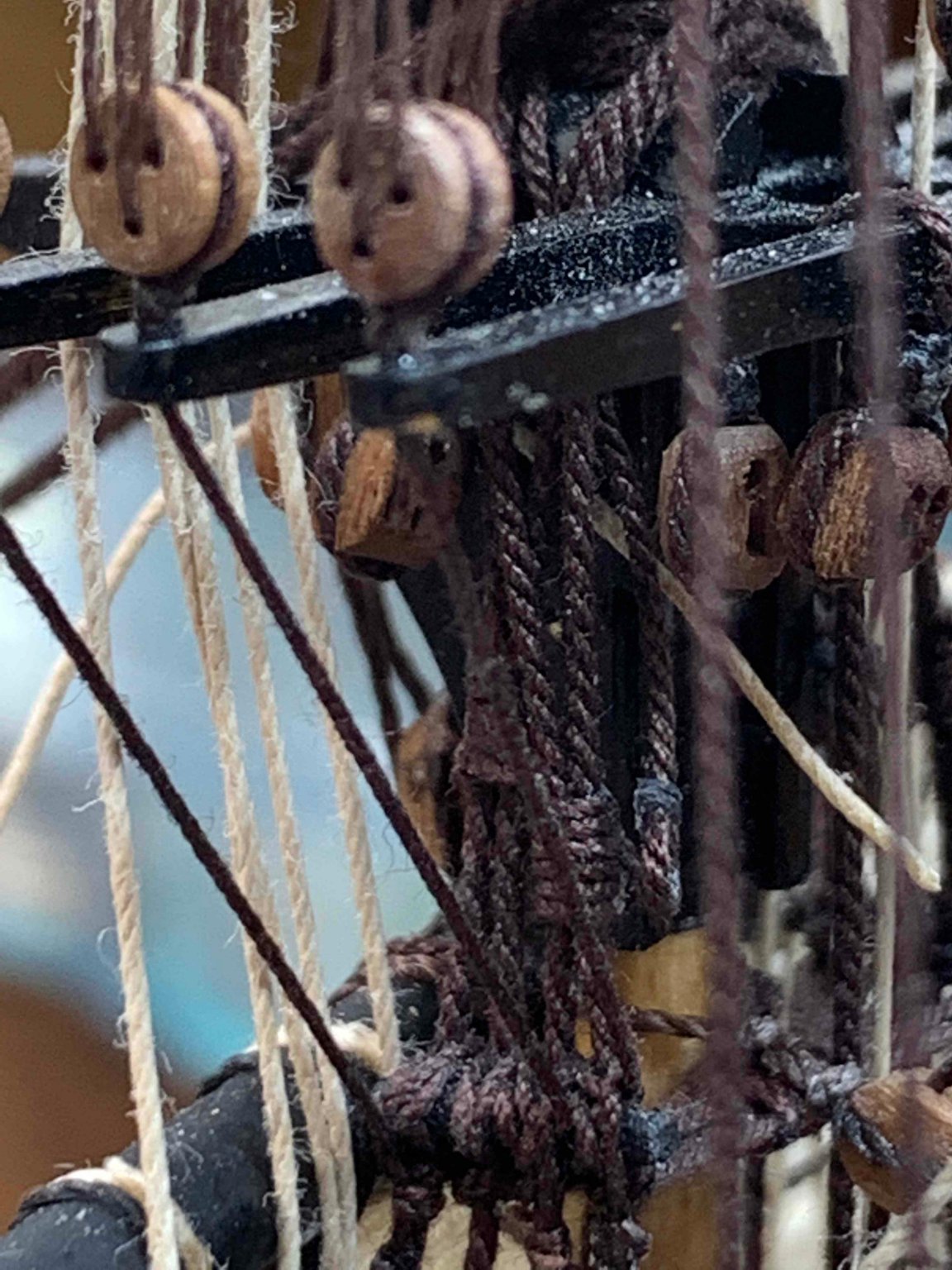
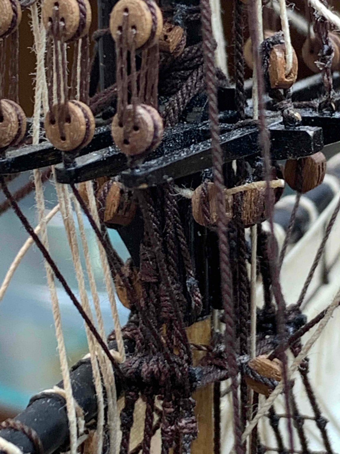
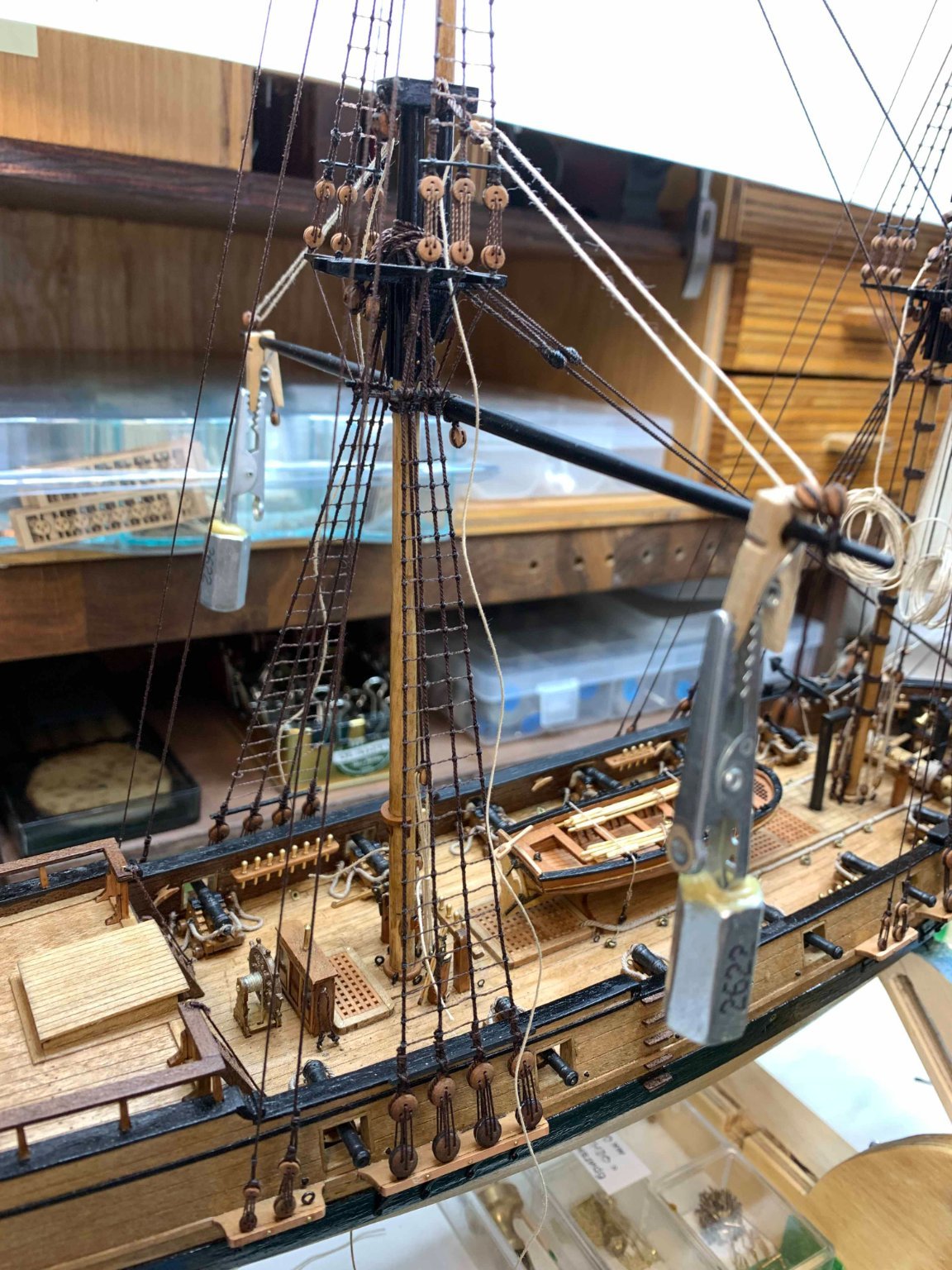
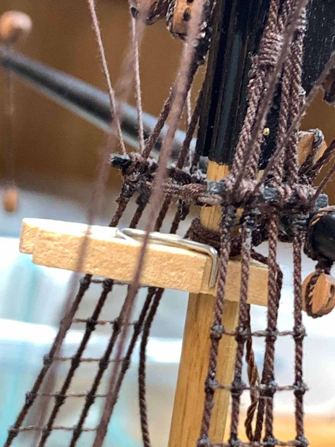
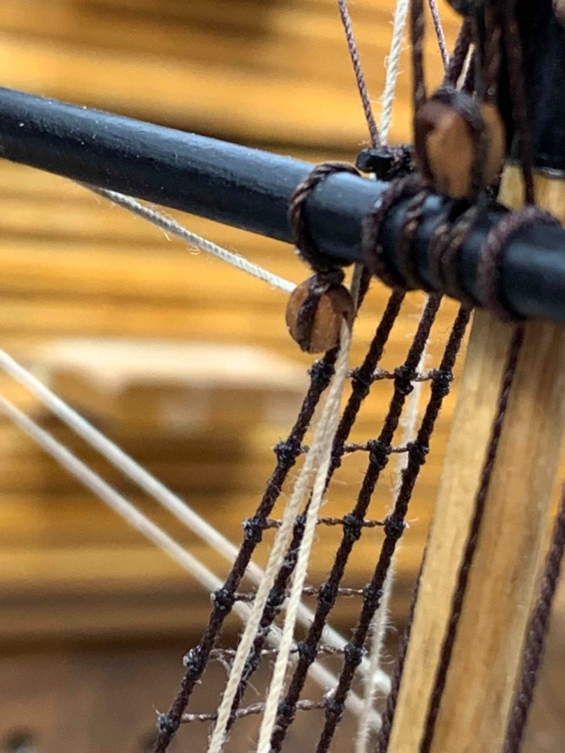
Continue with rigging... A little helper to assist with keeping the same distance for both blocks.. and the other side... Some random shots of blocks and rigging details.. if someone is interested in following one rigging line specifically, let me know and i will provide few pictures... From sailor' perspective... From bird' perspective... hopefully bird is not fully fed. While i was rigging this block, i rigged the wrong block, the one further on the left. All line was completed, ended in the third pin but had to do one more time, again. Practice makes it perfect.. Happy modelling..


- 275 replies
-
- 3
-
-
- phoenix
- master korabel
- (and 1 more)
-
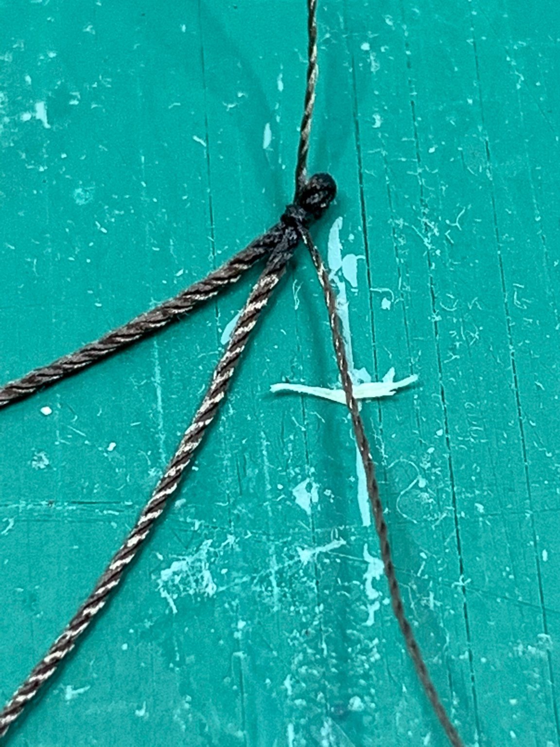
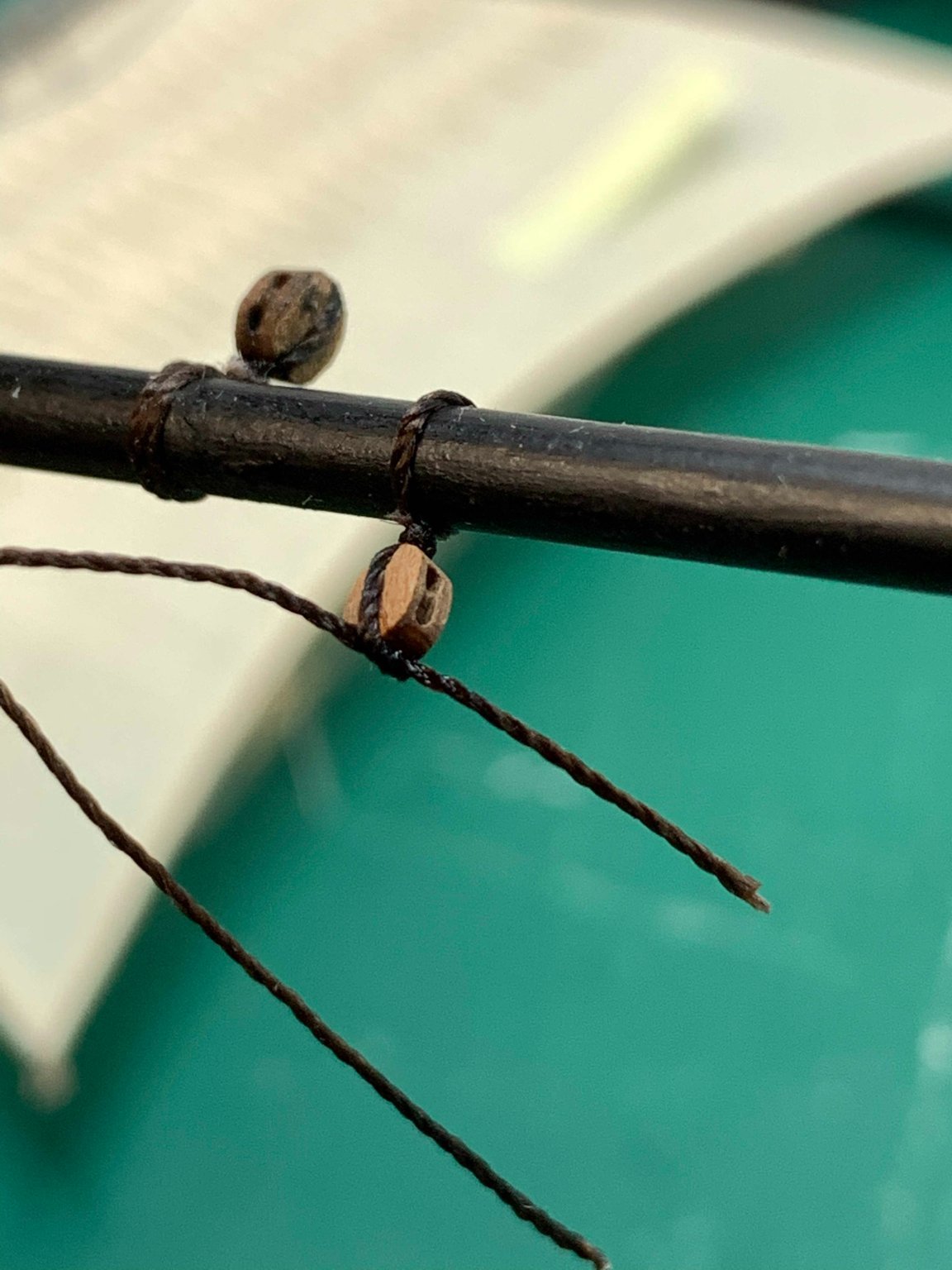
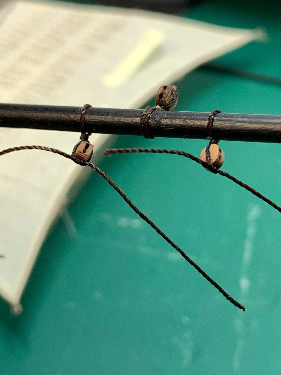
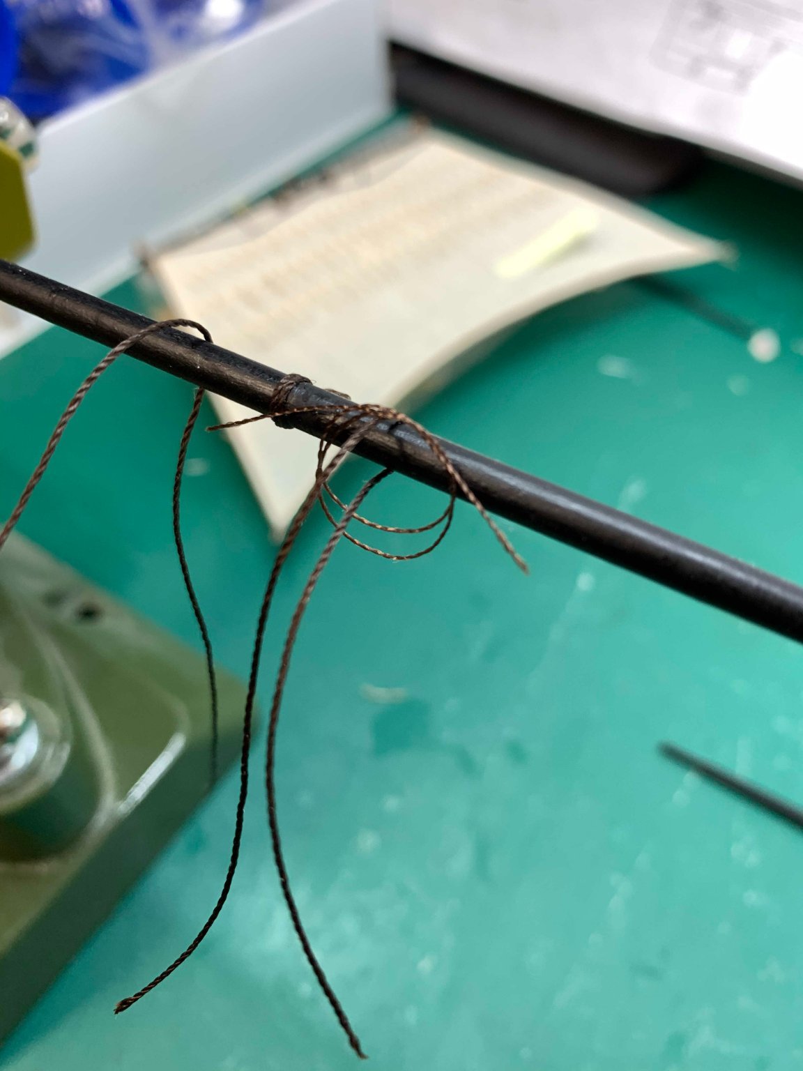
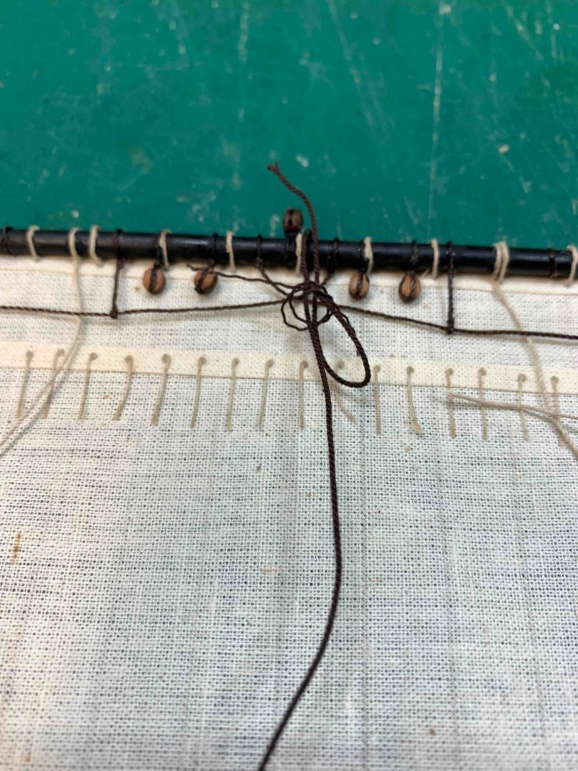
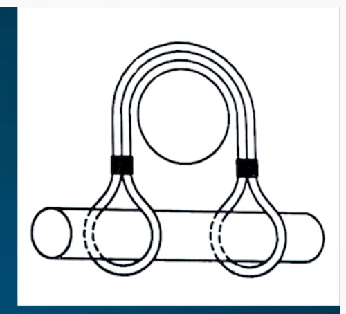
Started to work a bit on a mainsail. Not quite sure what is the name for this knot... ... but will try to reproduce it. And continue with sail rigging.. Happy modelling..


- 275 replies
-
- 3
-
-
- phoenix
- master korabel
- (and 1 more)
-
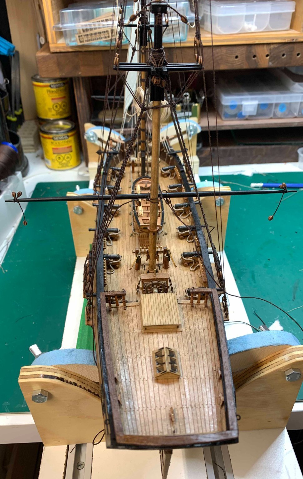
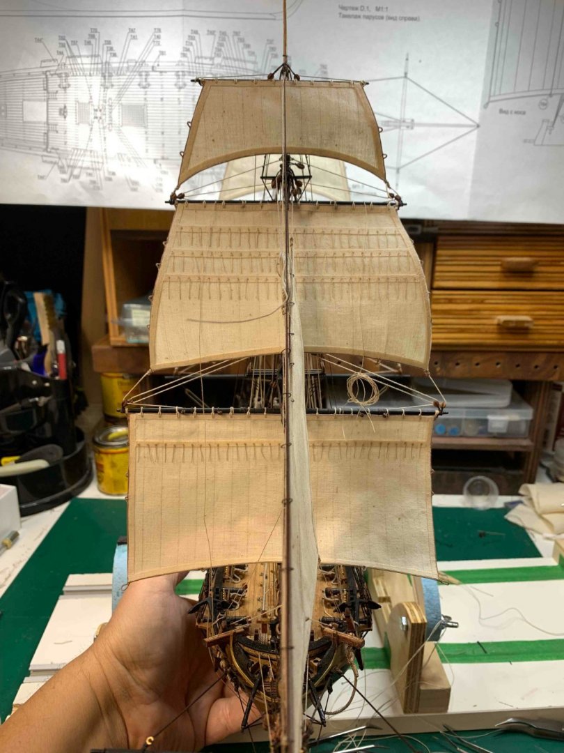
Wrapping up the wok from yesterday... A bit more progress.. weights on both ends to make sure the main yard is levelled.. Happy modelling...


- 275 replies
-
- 5
-
-
- phoenix
- master korabel
- (and 1 more)
-
Lets do some work on main yard... this is a fancy knot for a main yard.. On the way up... ... and up... One of two blocks that will need rigging... Little helper to keep all in one place.. Happy modelling..


- 275 replies
-
- 5
-
-
- phoenix
- master korabel
- (and 1 more)
-
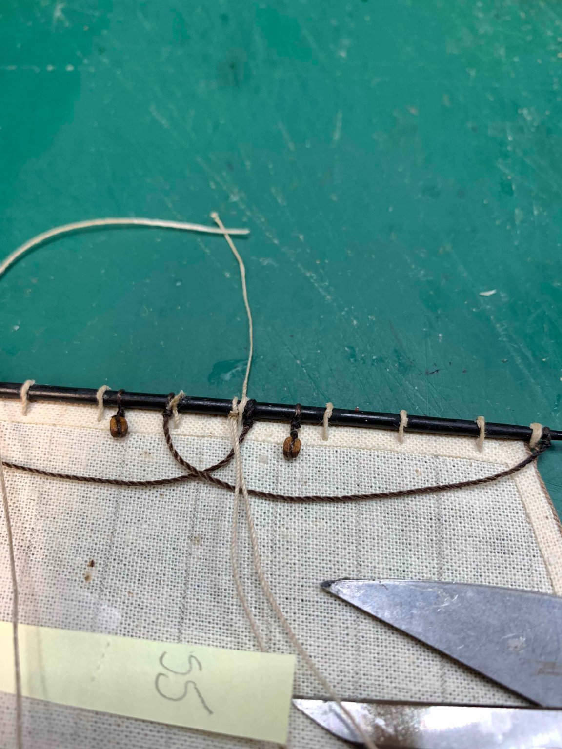
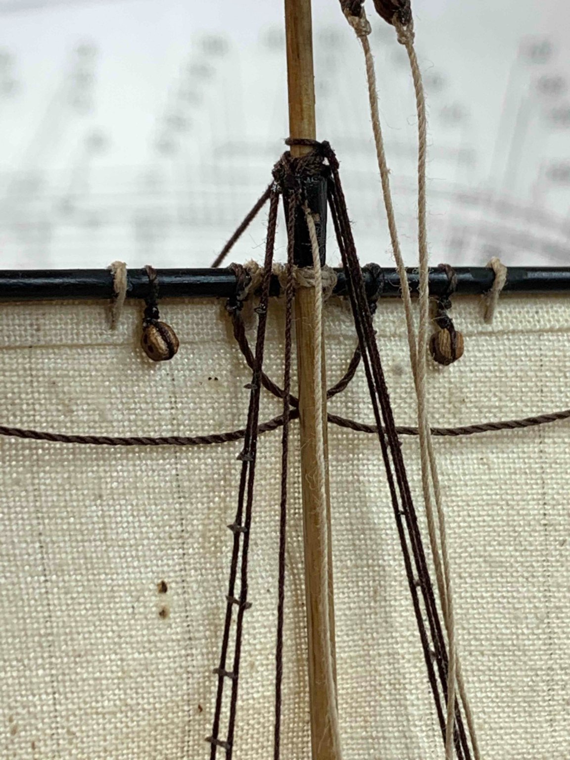
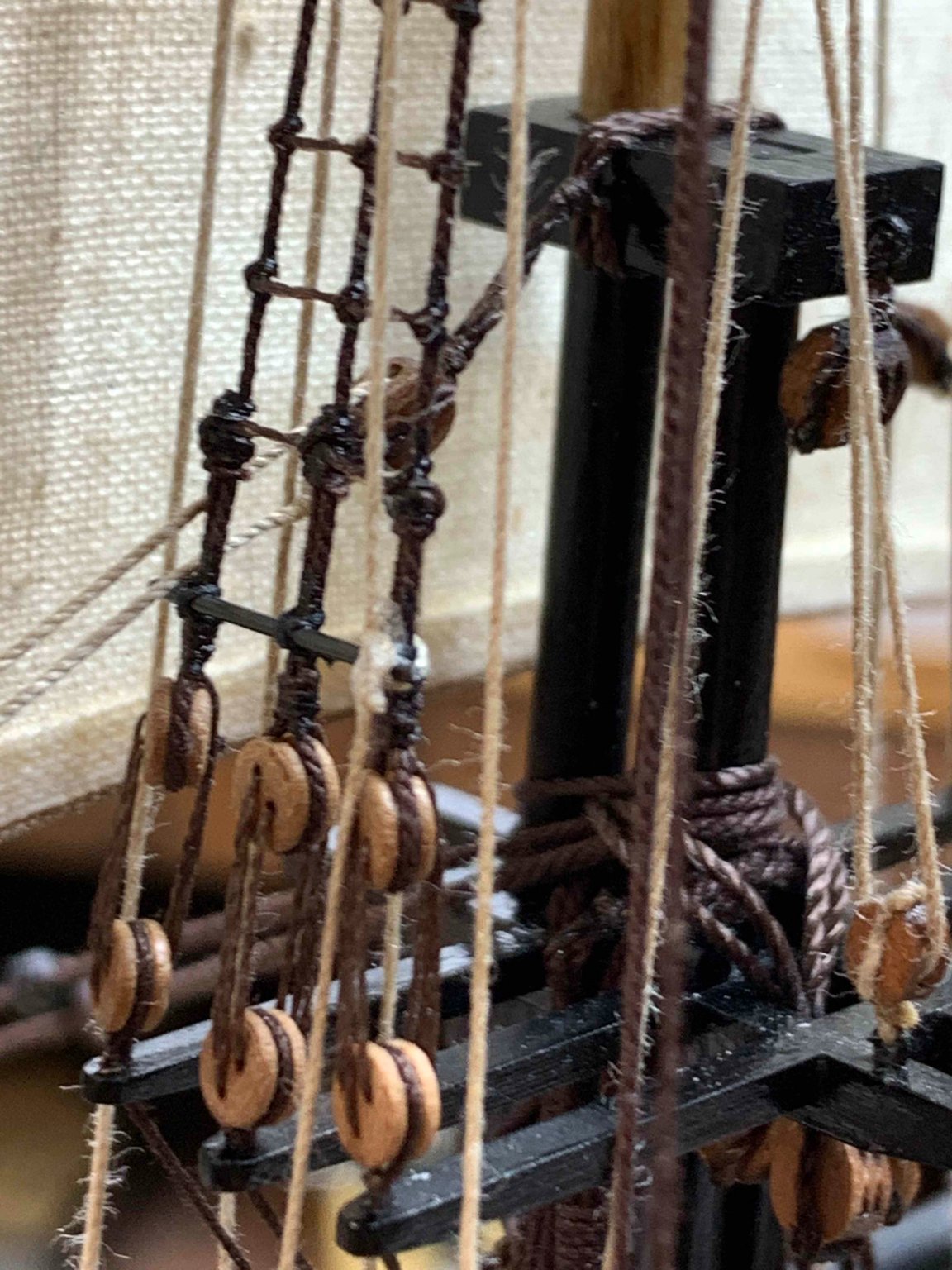
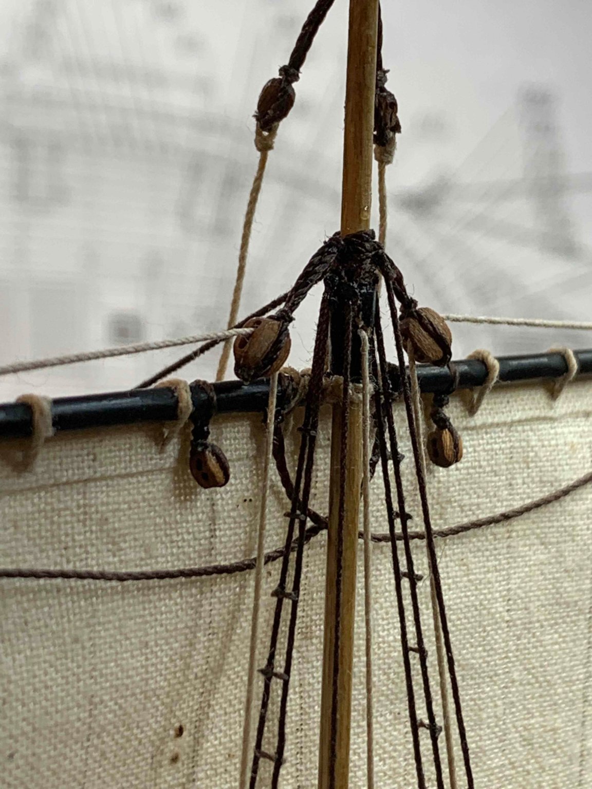
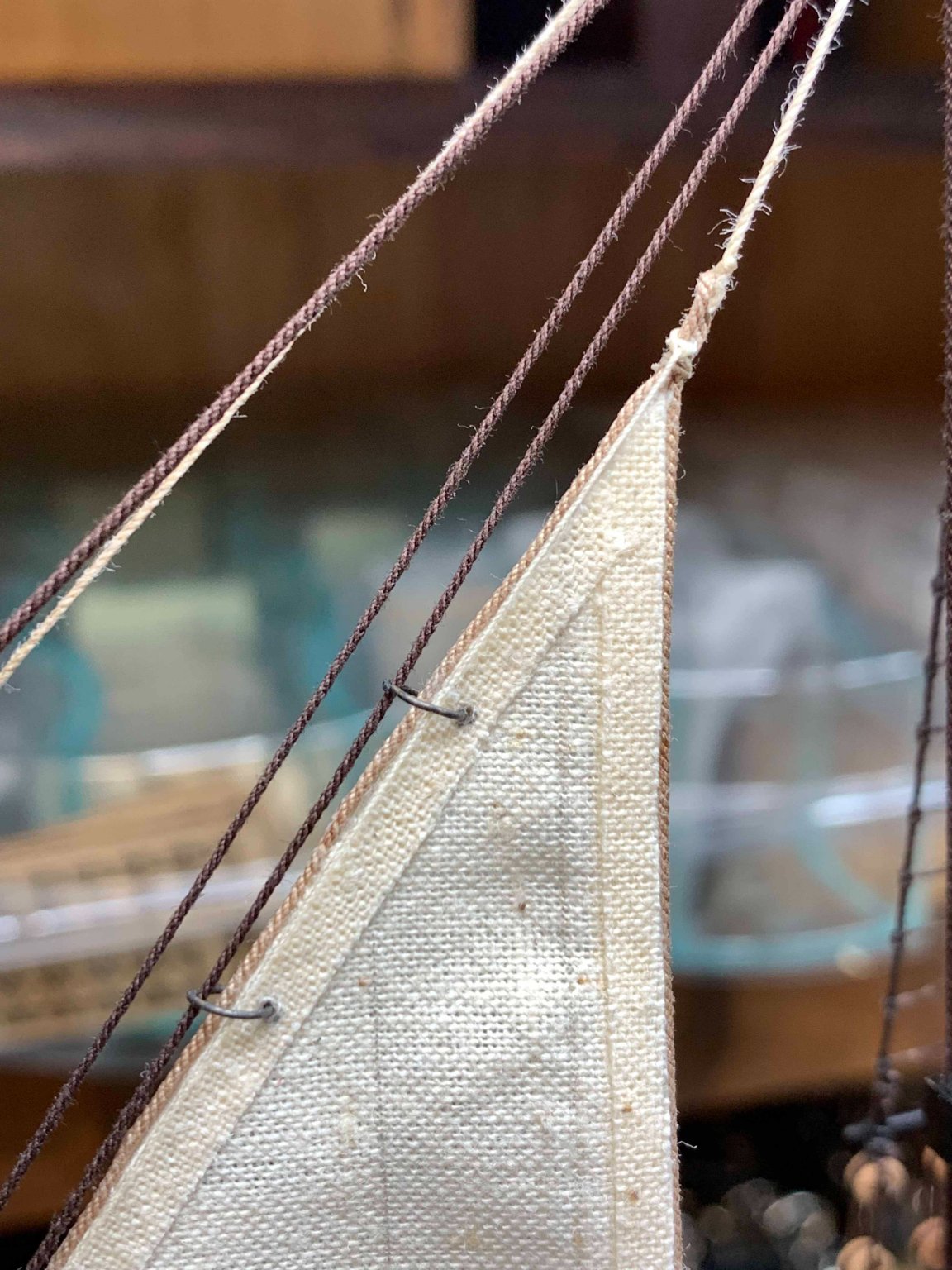
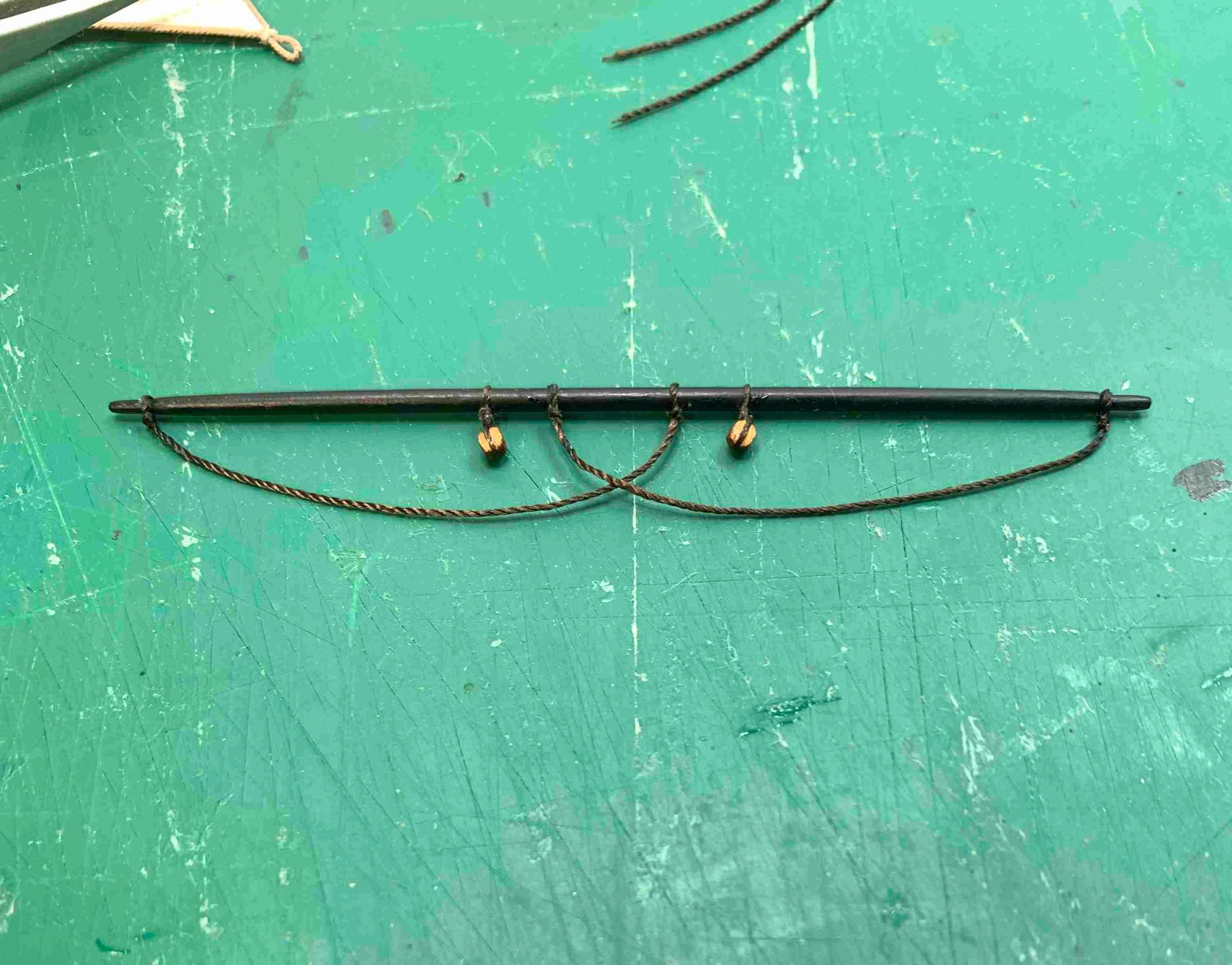
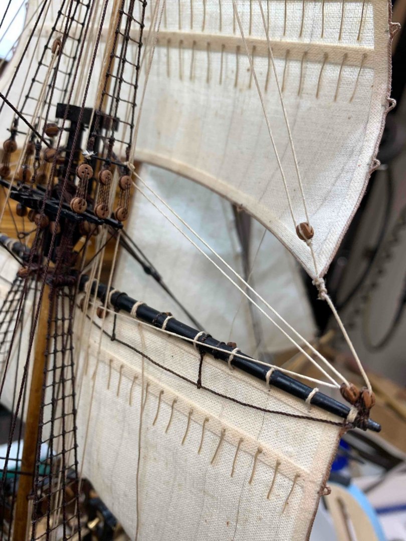
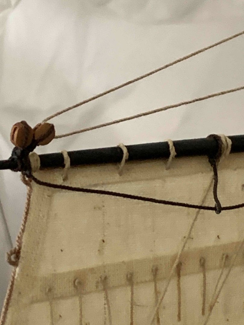
The pedants are attached to the sail with special knot, and the rope length has to be adjusted; with installed sail, the pedants length will be different .. Staysail downhaul is also installed... Happy modelling..


- 275 replies
-
- 4
-
-
- phoenix
- master korabel
- (and 1 more)
-
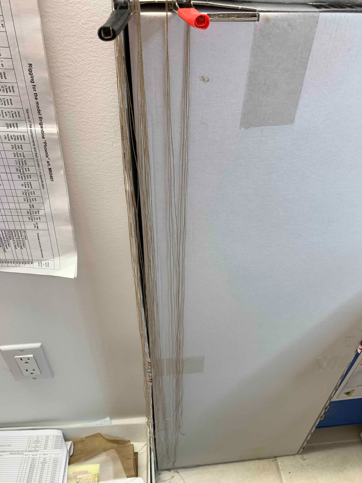
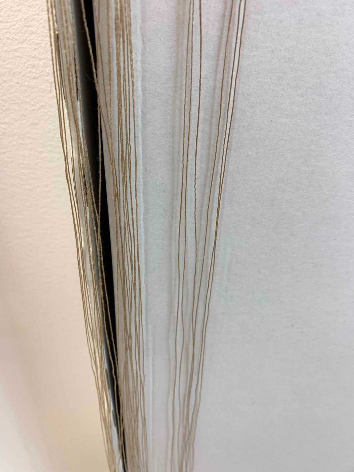
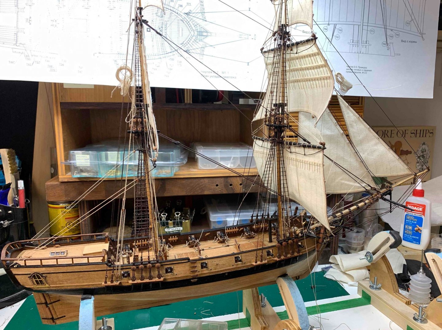
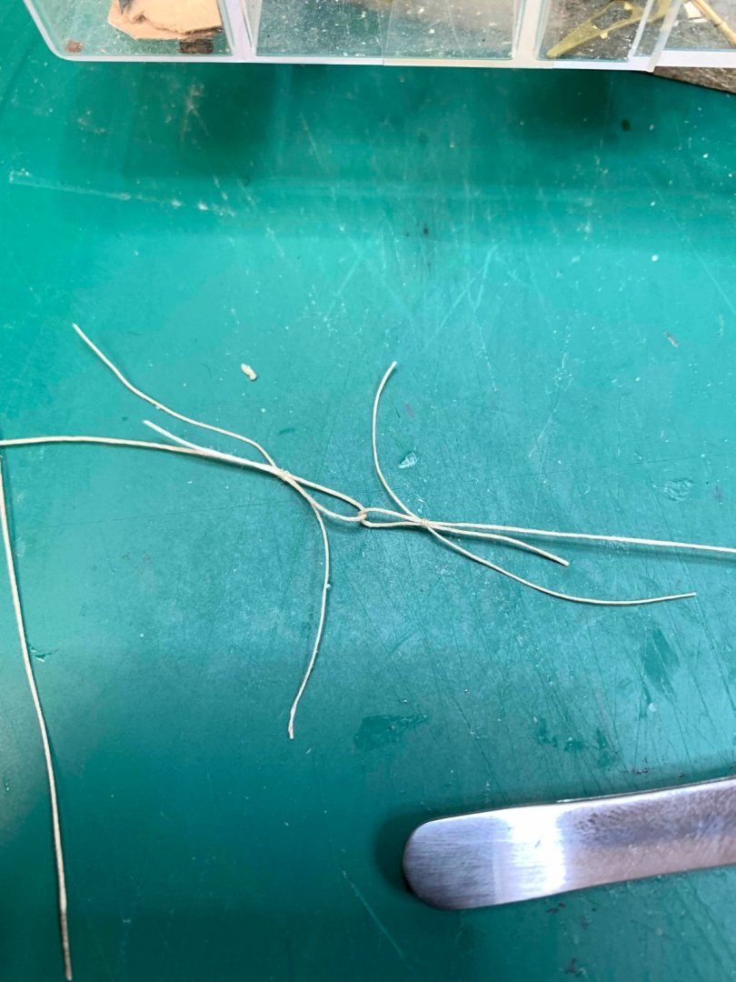
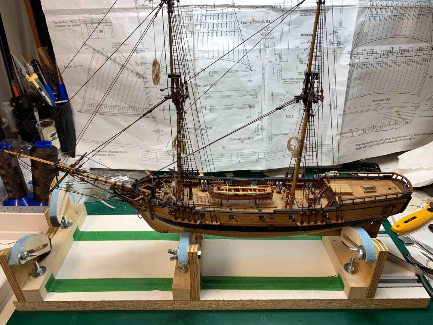
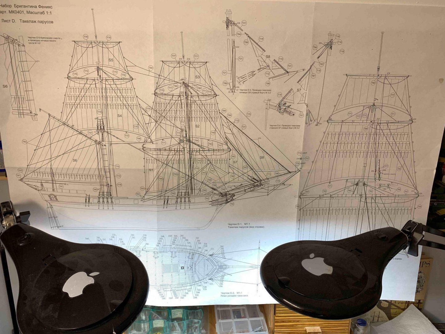
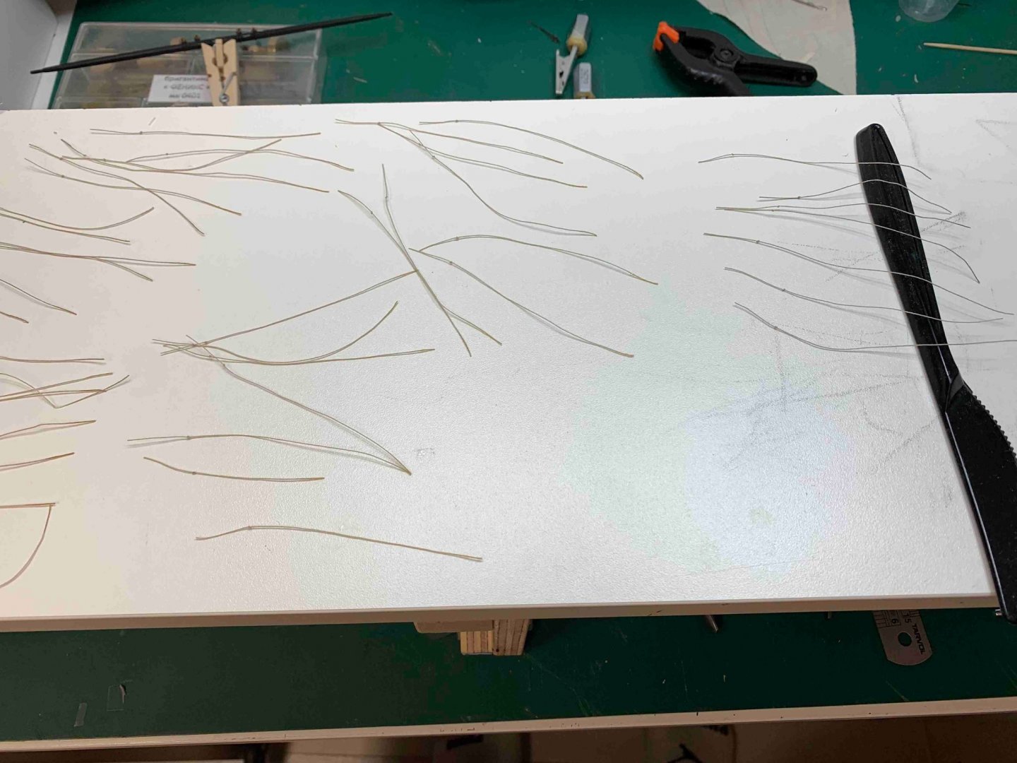
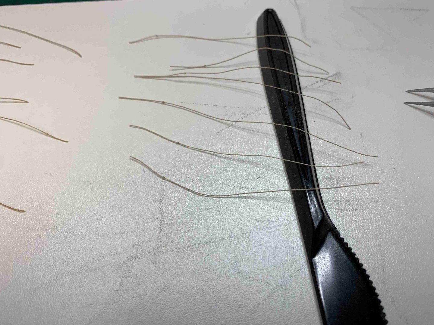
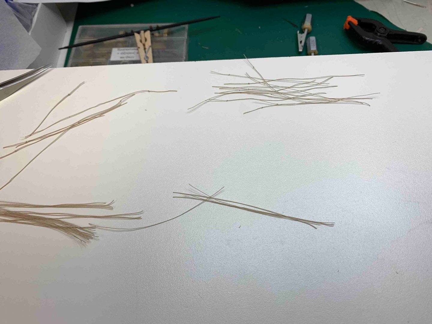
Making few 0.3mm ropes, using crochet lines and Golden oak stain. I usually cut the lines in 1mm length, deep one line at a time in the stain and pull it out, at the time i drop the whole line in the stain. This prevents a line to stay in the stain for too long. This allows me to somehow control the beige colour shade of the lines.. then let it dry for a day... It is time to bring the model back on the table... ... and to replace the plan All sails appears to be done.. Work will start on a jib by making a holes for rings.. and making 7 rings in 3mm diameter. The rings are blackened and polished before mounted on the sail.. Then the sail is attached ... Then a tack cringle is attached to the parrel using a simple square knot. Next, the halyard is attached to the head of the sail.. ... and it will be tight to the cleat using a 3.5 mm block with an iron hook.. Happy modelling...


- 275 replies
-
- 3
-
-
- phoenix
- master korabel
- (and 1 more)
-
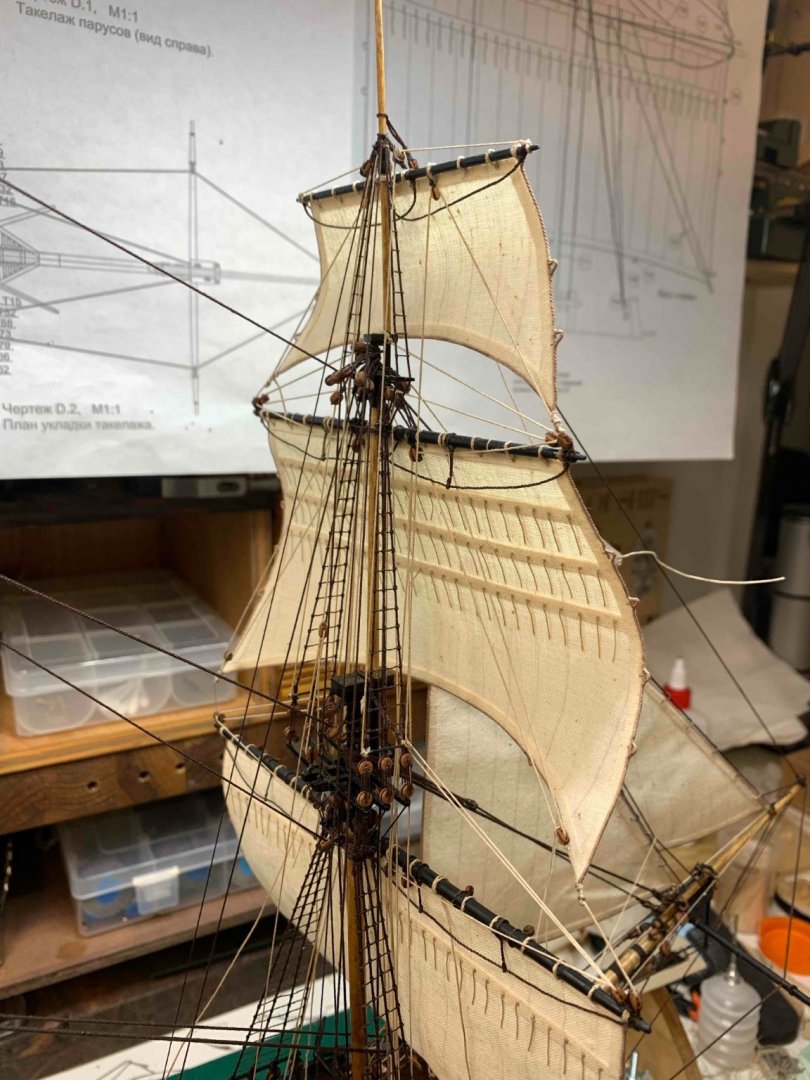
Completed so far.... Still working on sails... Happy modelling...


- 275 replies
-
- 5
-
-
- phoenix
- master korabel
- (and 1 more)
-
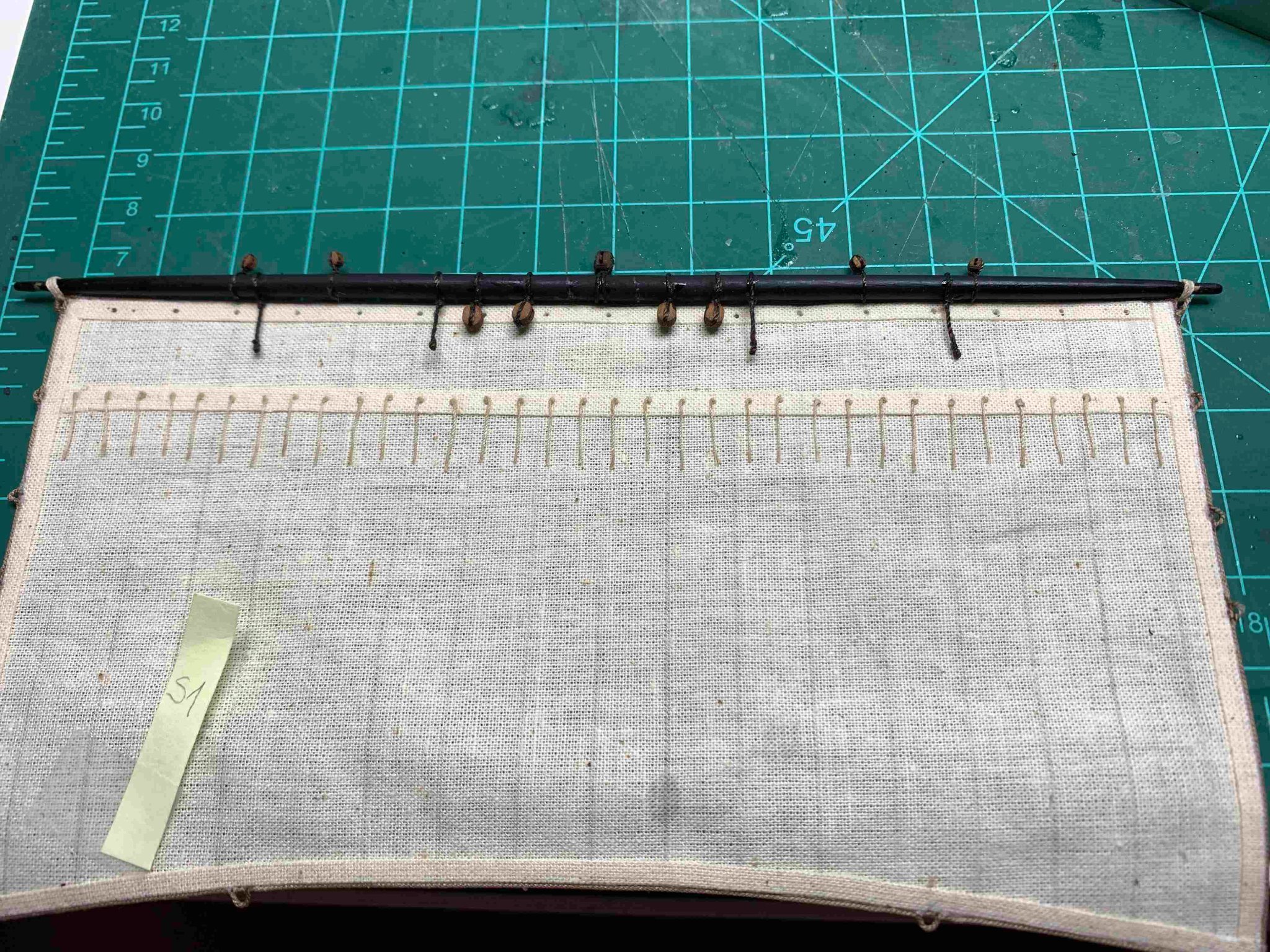
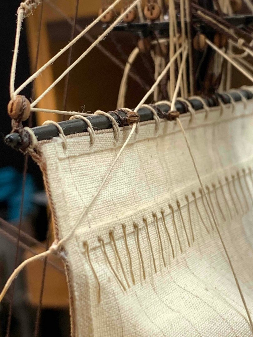
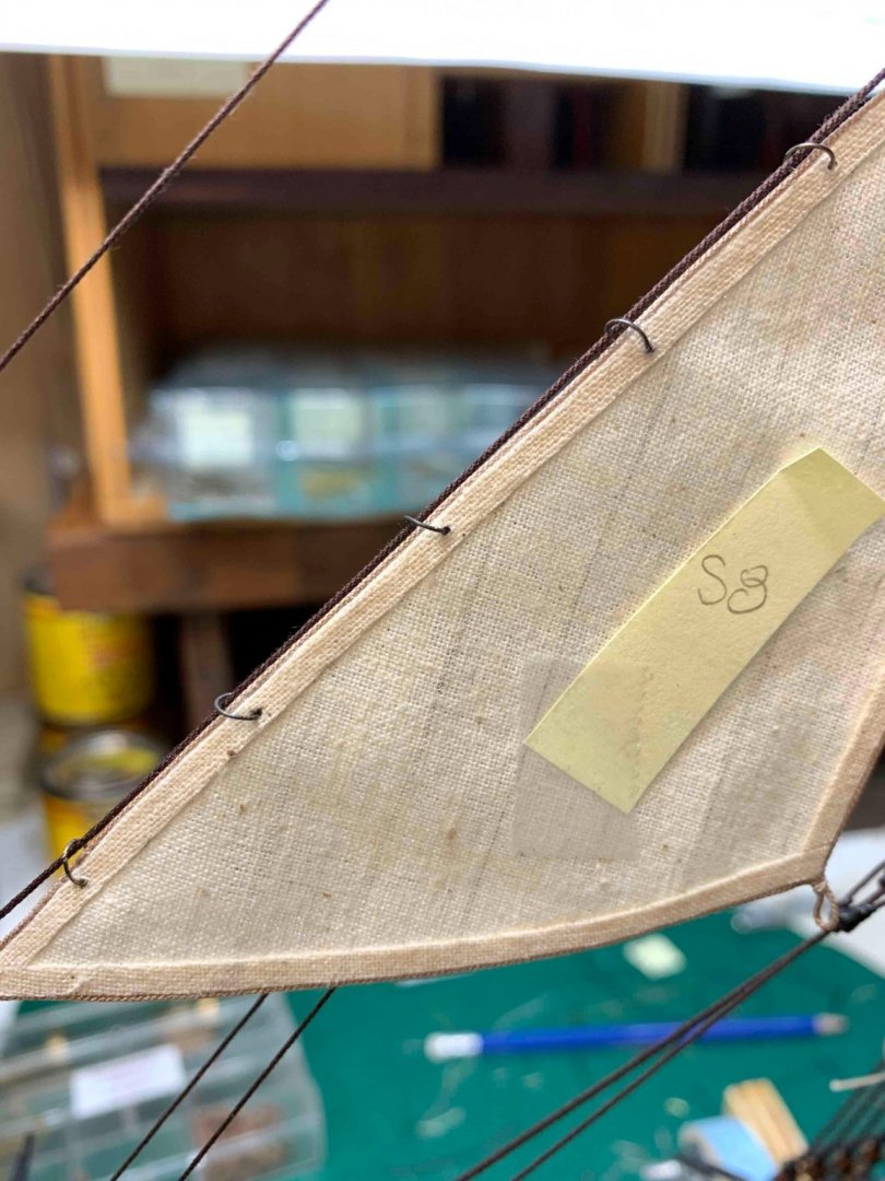
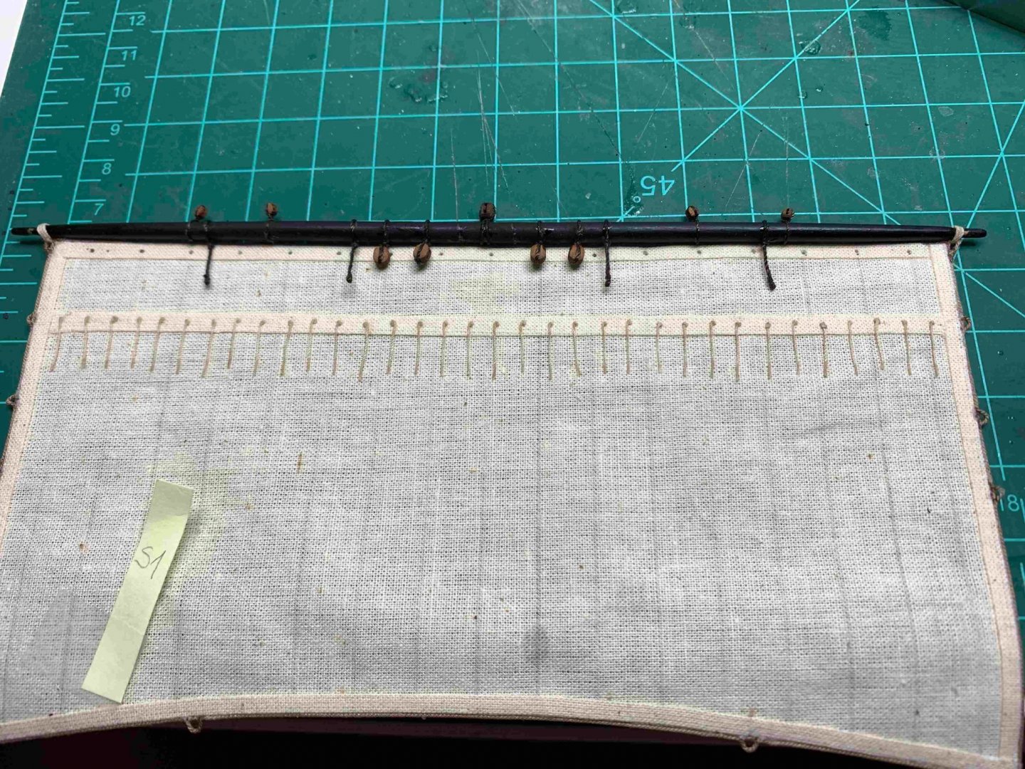
Marking the position of reef lines... Production line, knot making process... Freezing the top of a line with a drop of CA glue... After making holes in the sail, the reef lines are pushed thru... 50/50 diluted white glue assist keeping the knot positioned... The ship cradle, once turned up side down, serves as a good, small table for tasks that require precision and patience.. this is part of making a knot on the other side of the line.. After reef lines haircut is done... few lines still need a bit of adjustment... Next sail, S1.. and completed... Happy modelling..


- 275 replies
-
- 4
-
-
- phoenix
- master korabel
- (and 1 more)
-
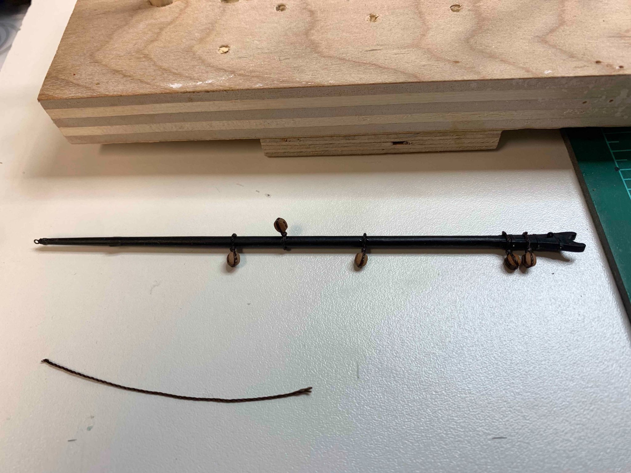
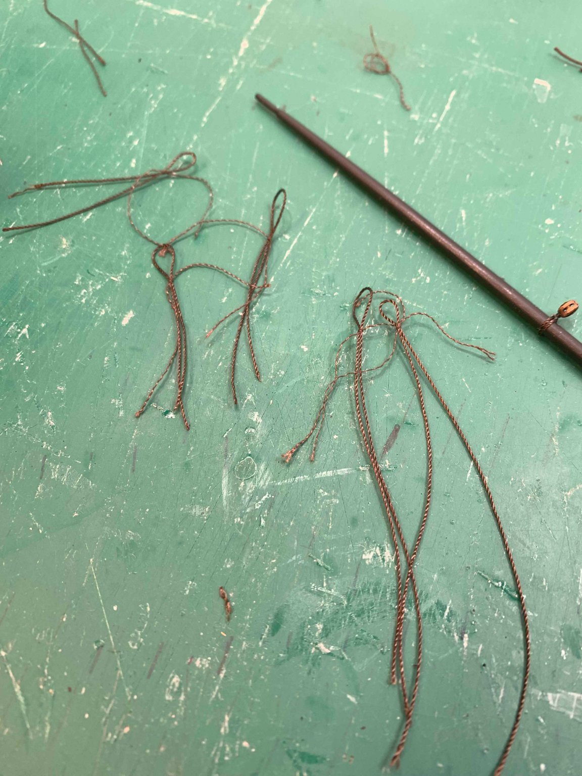
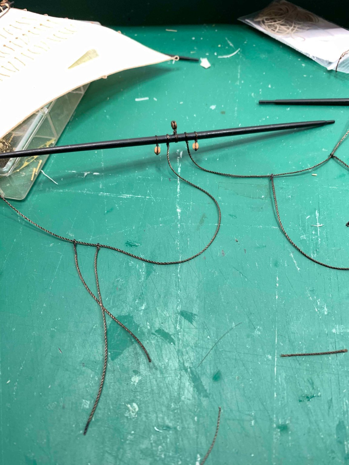
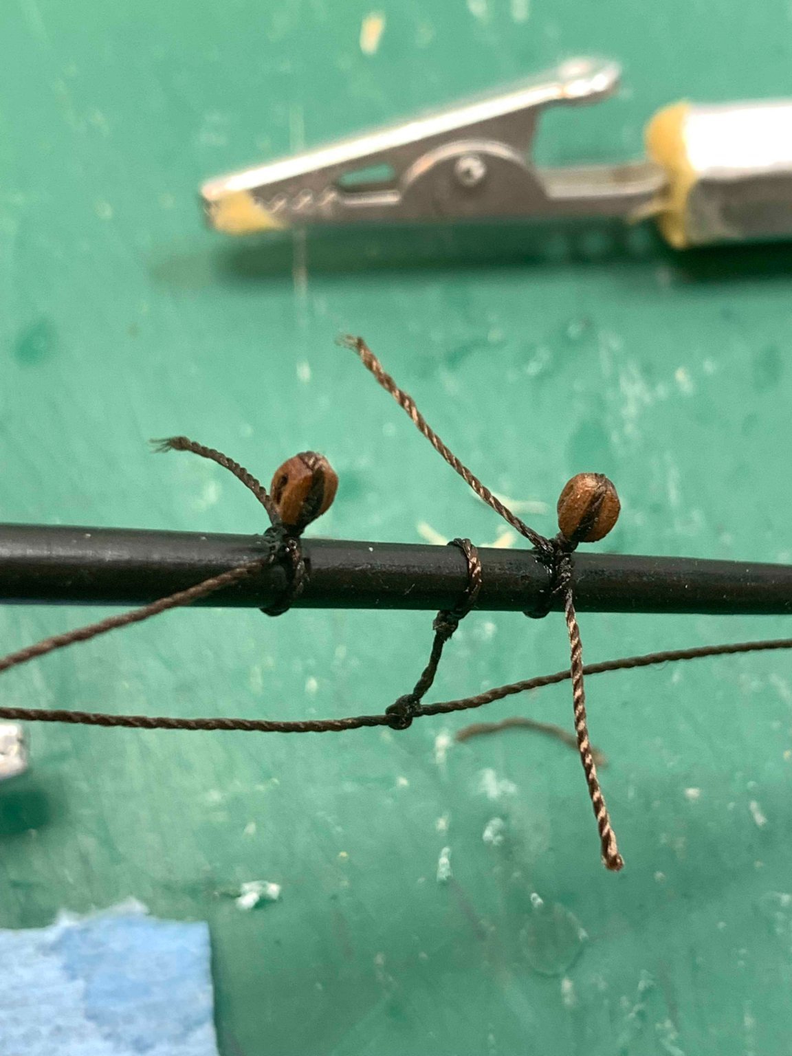
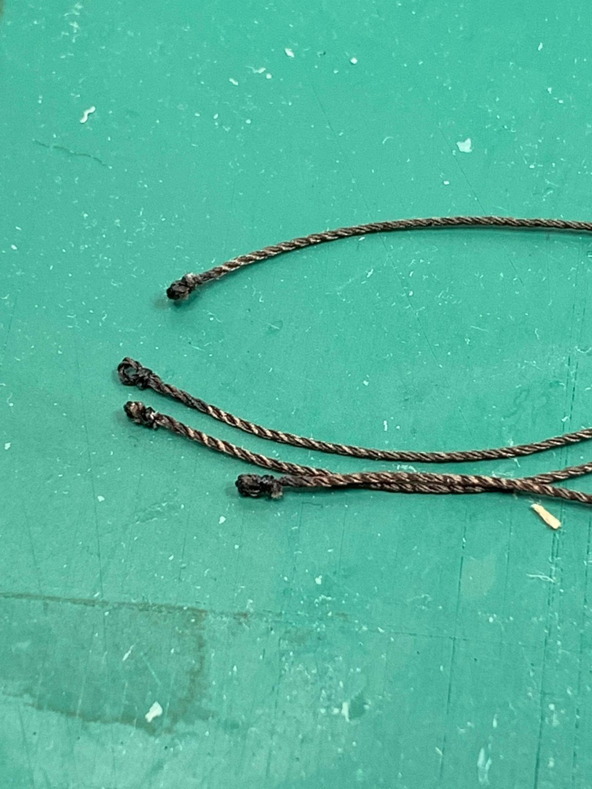
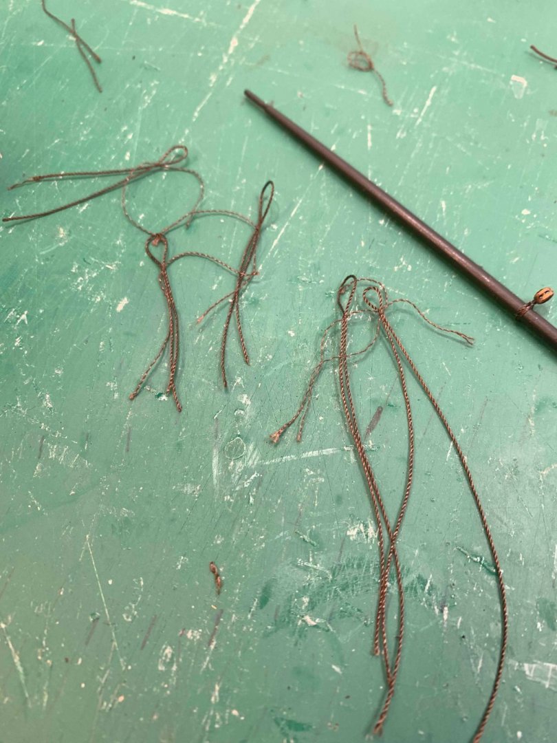
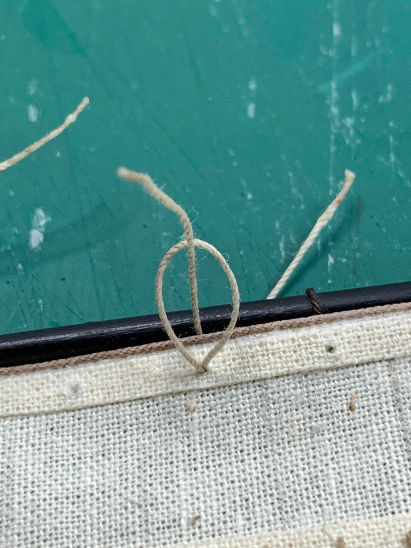
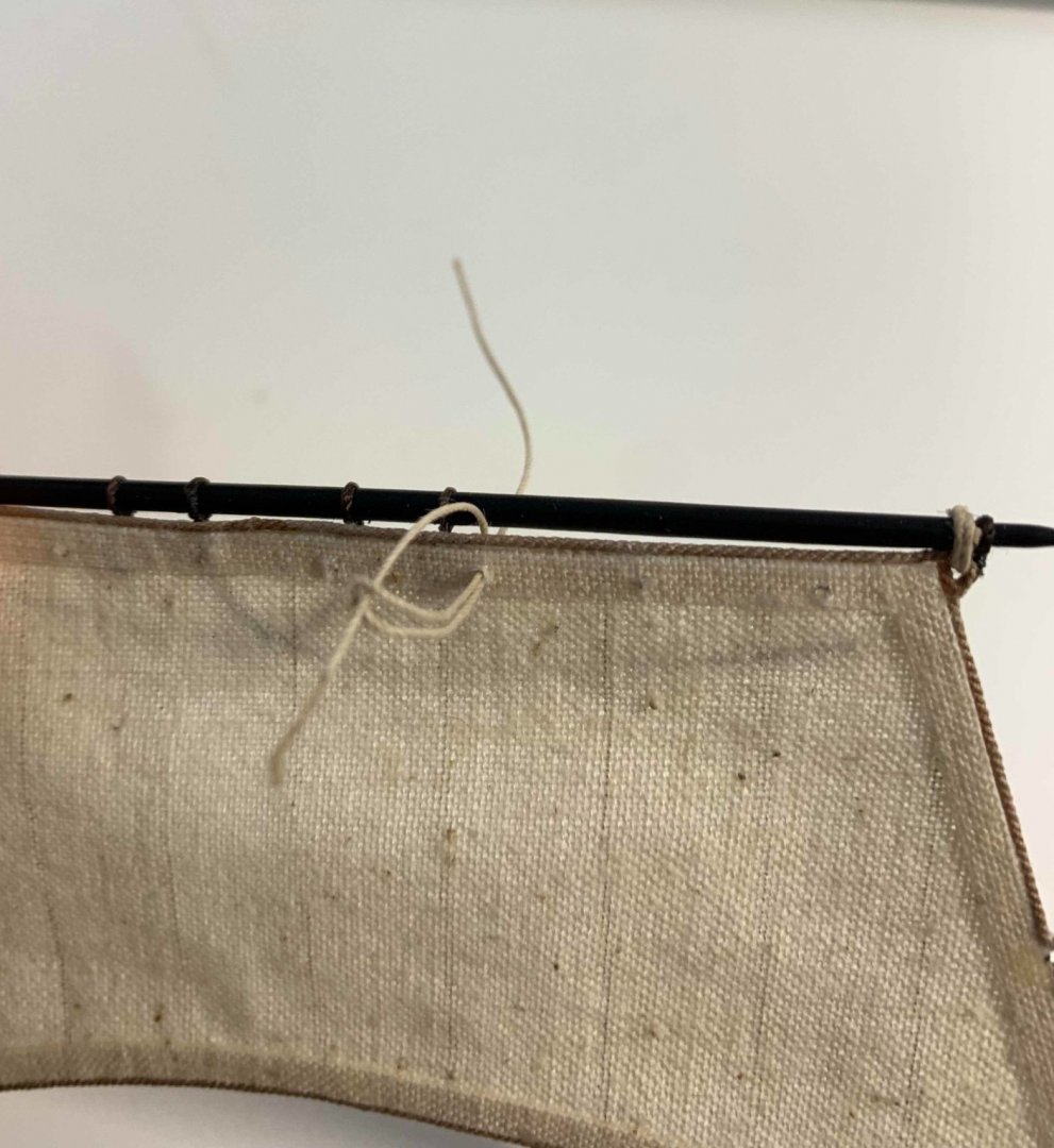
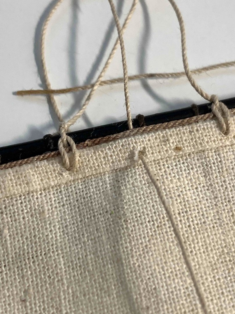
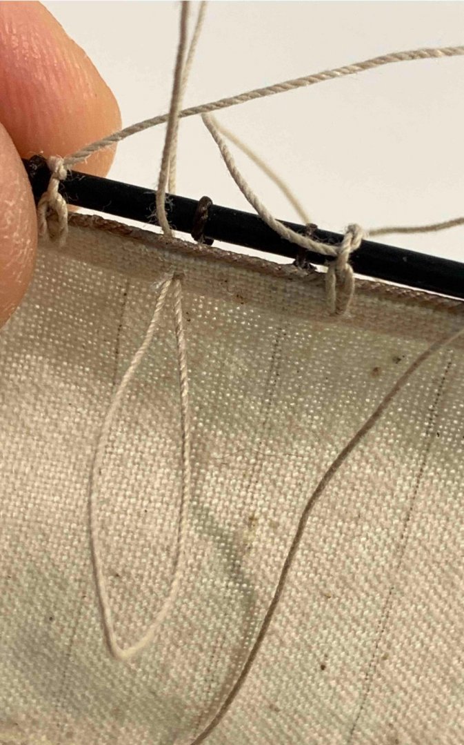
Working on blocks, different sizes, for different yards... a bit of serial production. I used a bit of CA glue to freeze the block and now rope is slightly stiff; need to massage it so it will fit around the yard.. A foot rope is also installed; slightly different approach this time. First i made an eye... Cut it with extra length... then drag the main rope line thru with a help from this fancy tool... The the lines were tight to the yard in appropriate length.. I will adjust foot rope to look a bit more realistic... Happy modelling...


- 275 replies
-
- 2
-
-
- phoenix
- master korabel
- (and 1 more)
-
A bit more work completed.. I have tried with another material; this time was able to pull strings for simulation... and it looks very nice... Will use it next time.. Two sails done... Happy modelling..


- 275 replies
-
- 2
-
-
- phoenix
- master korabel
- (and 1 more)
-
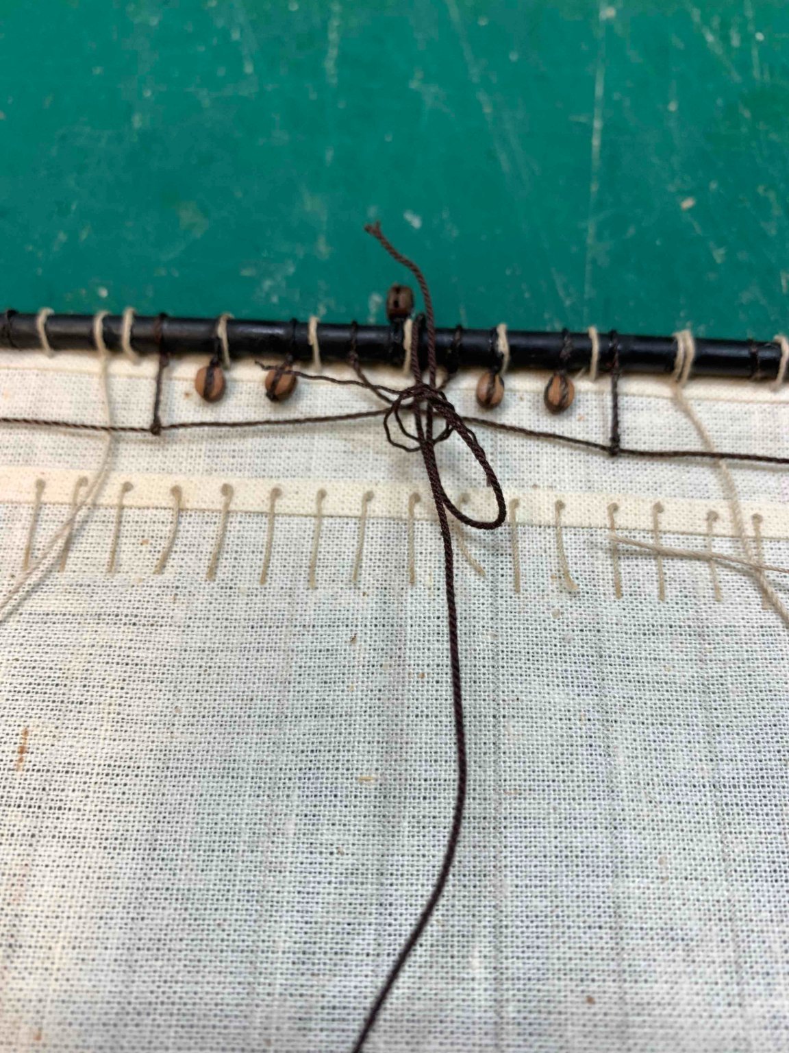
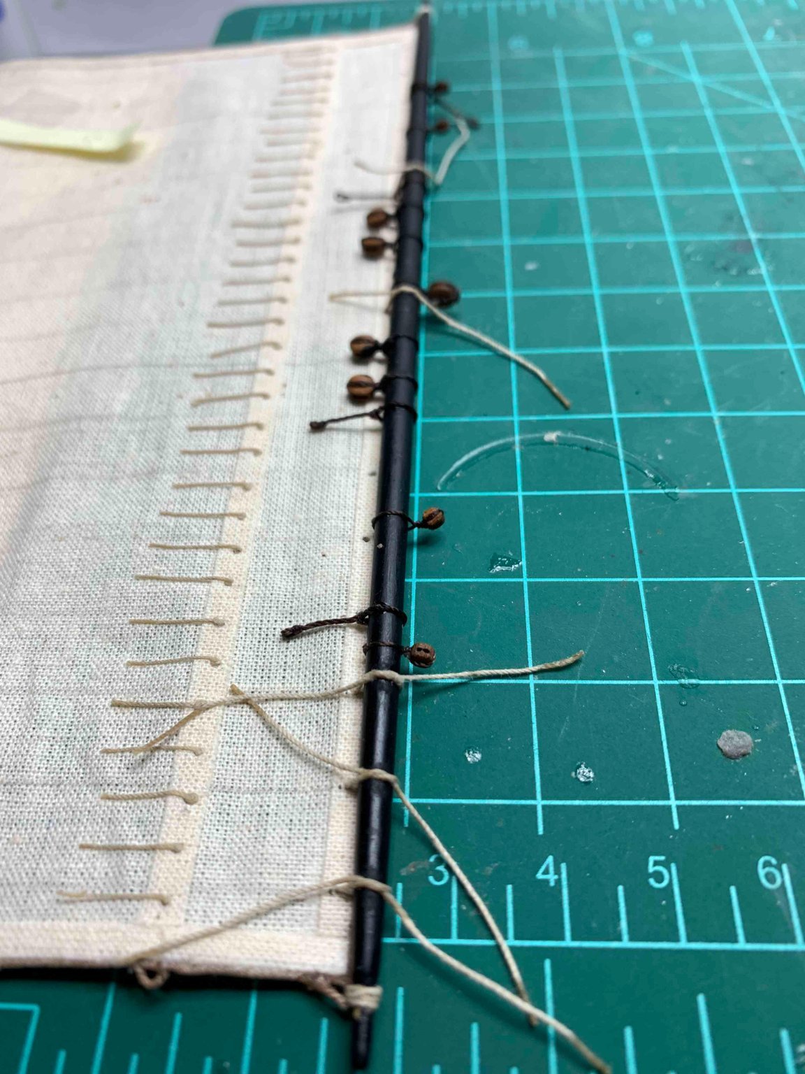
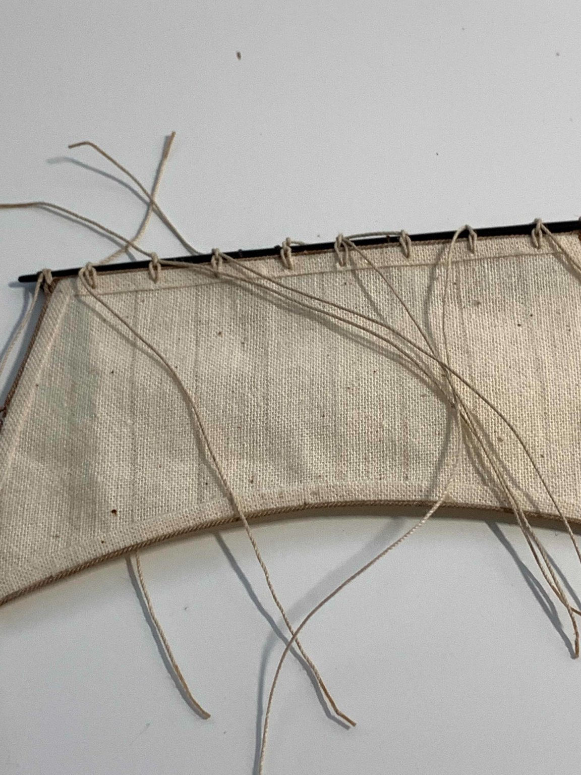
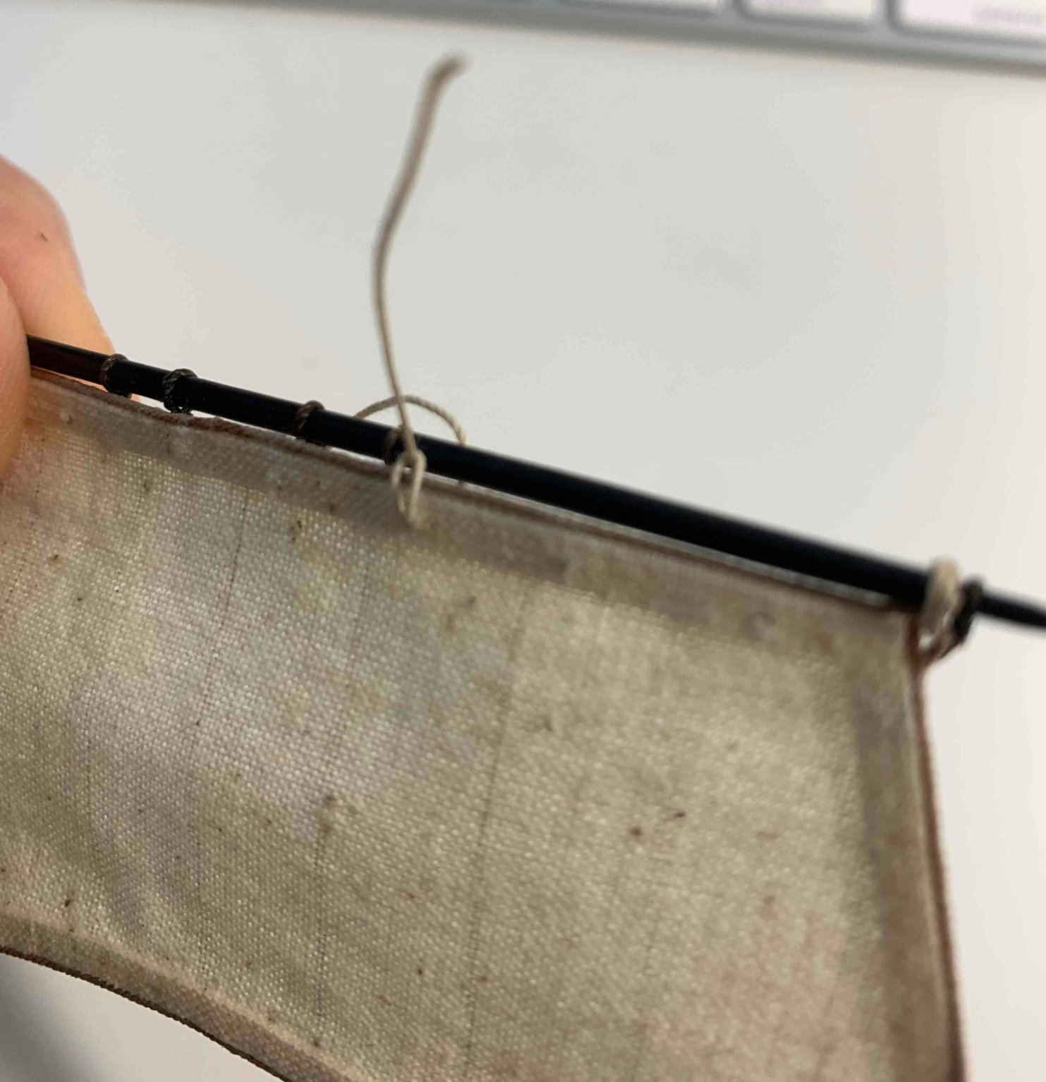
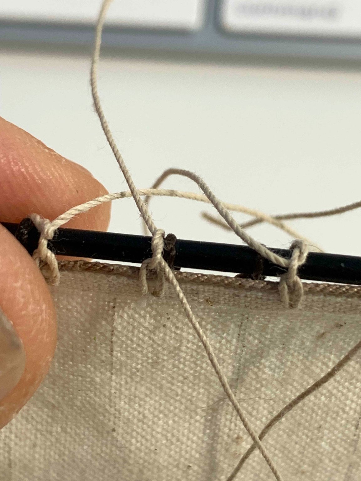
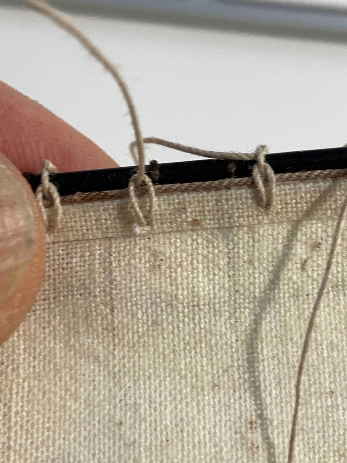
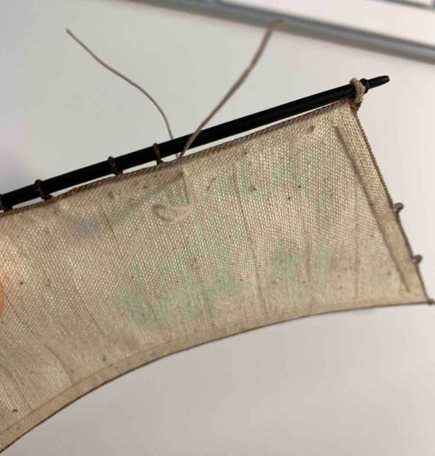
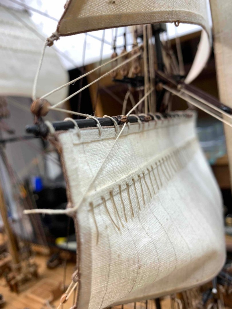
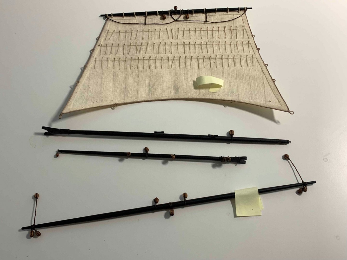
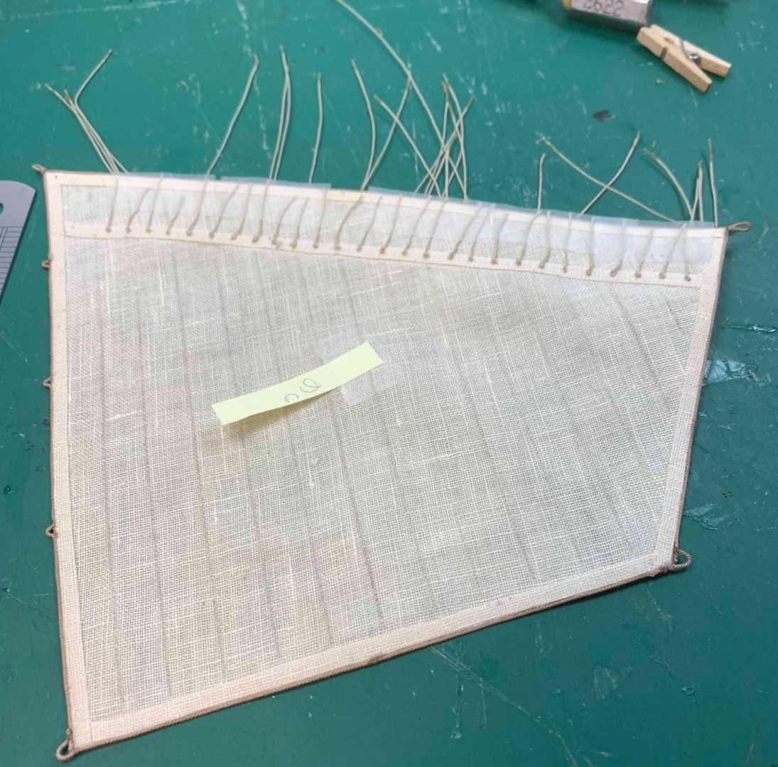
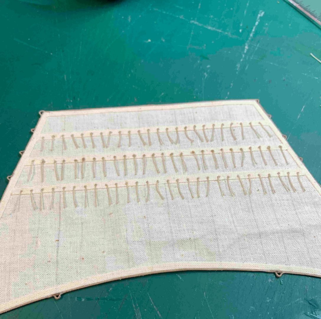
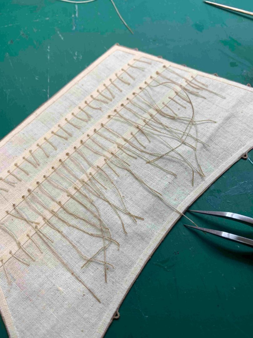
A bit of a white glue, diluted 50/50 to freeze the reef band... A bunch of reef lines were pre-cut, a knot was tight on one end and opposite end frozen with a drop of CA glue so it can easily go thru the hole.. Once all lines with a knot were pushed thru the sail and secured with a drop of white glue, the work on opposite side started by making another knot... Then all lines were cut to the length.. Just to break a bit from reef lines, started to work on attaching a sail to the yard.... ... first attaching the corners of a sail with a strangle knot... The holes for robands were also predrilled.. Then it becomes very hot in my little workshop so continue tomorrow... Happy modelling...


- 275 replies
-
- 2
-
-
- phoenix
- master korabel
- (and 1 more)
-
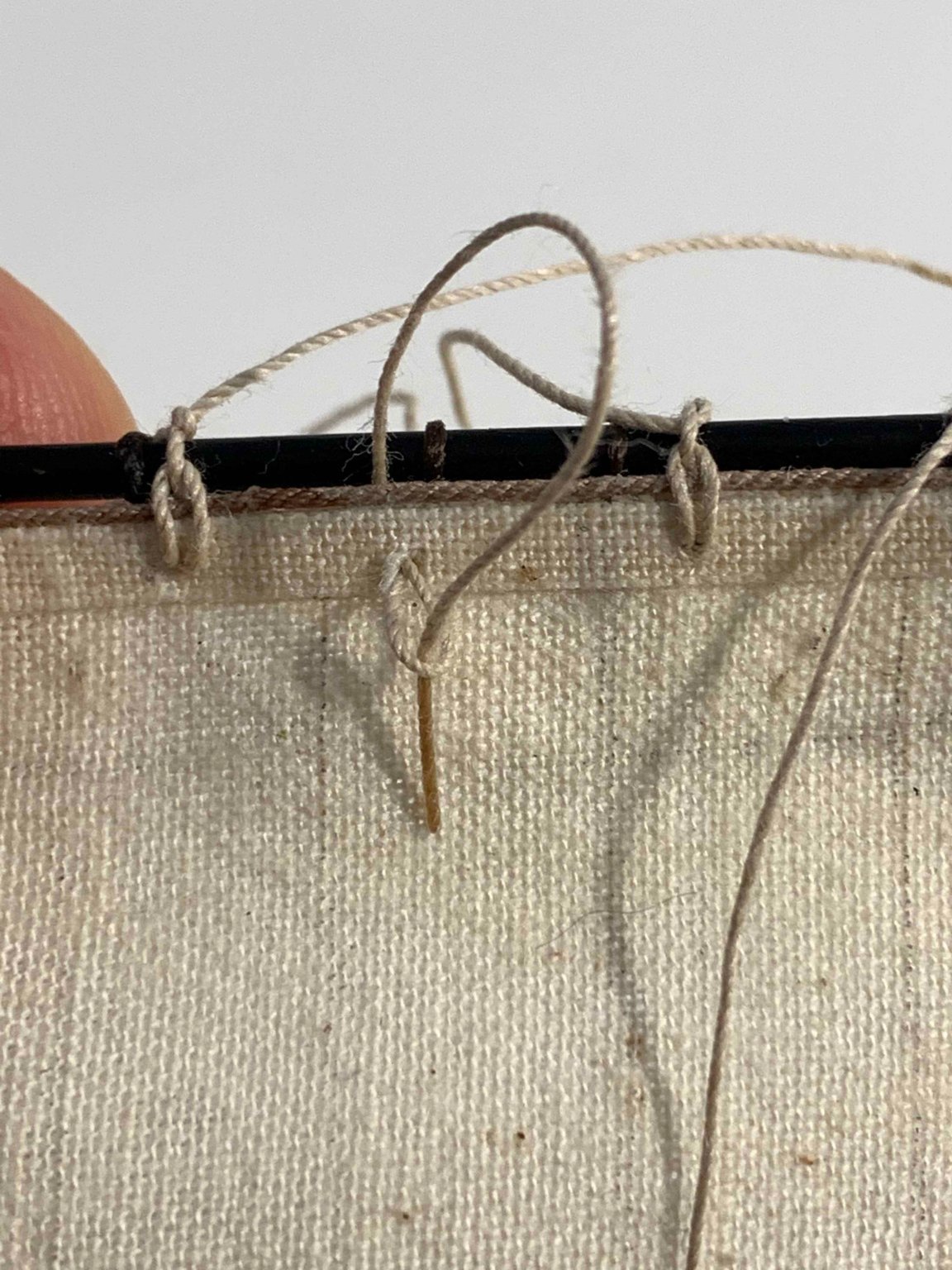
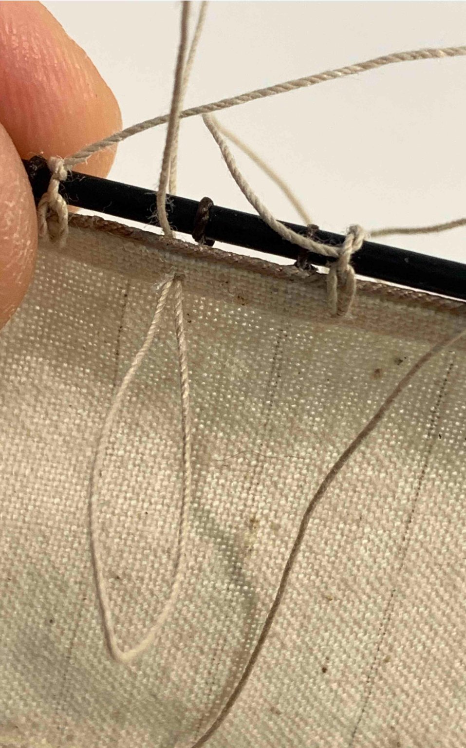
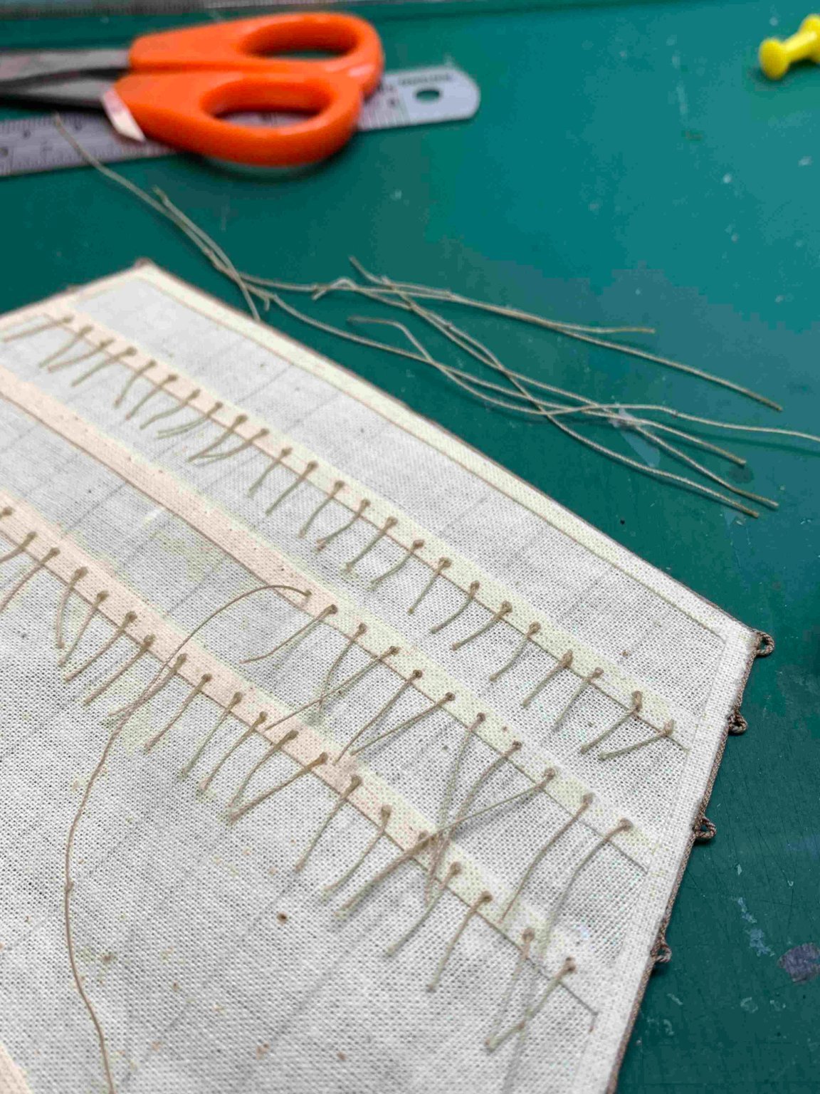
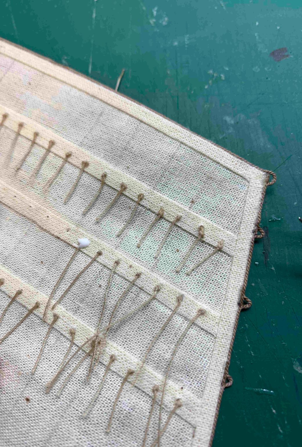
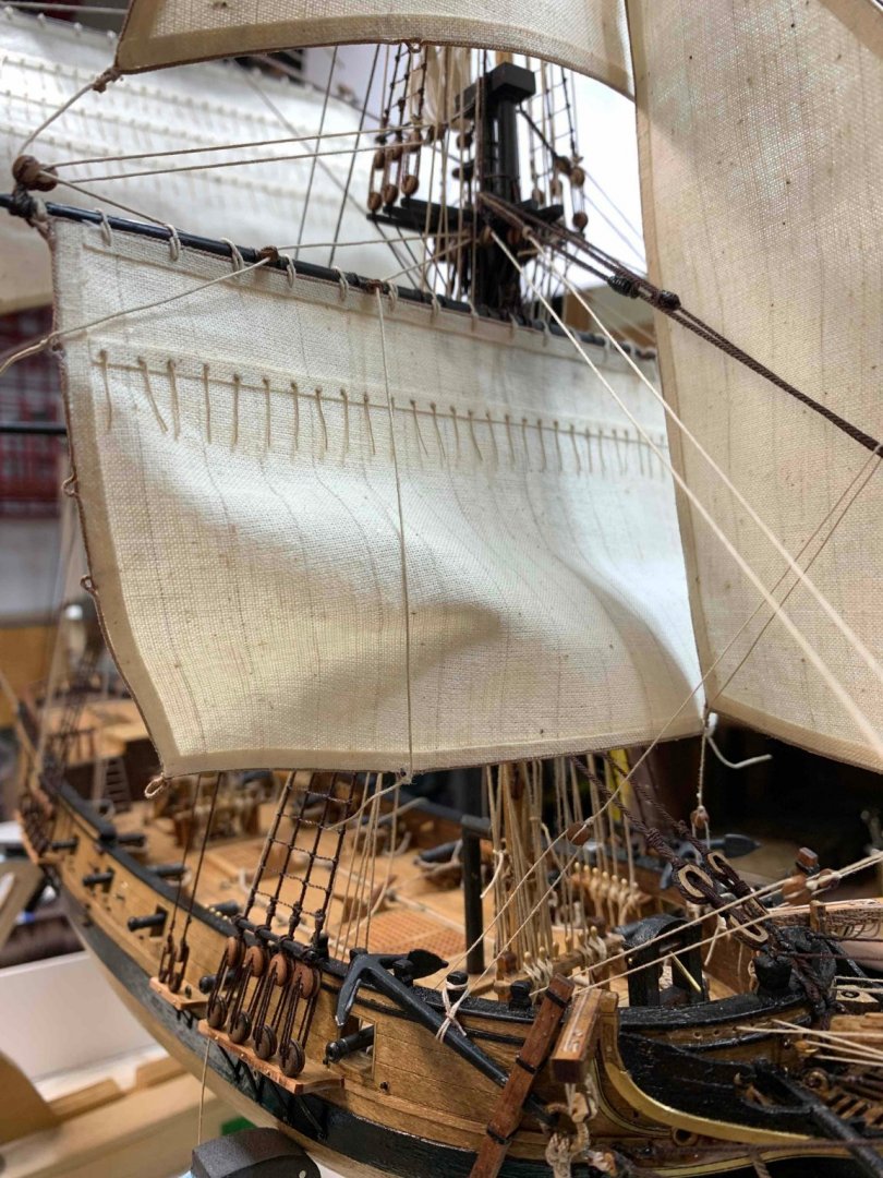
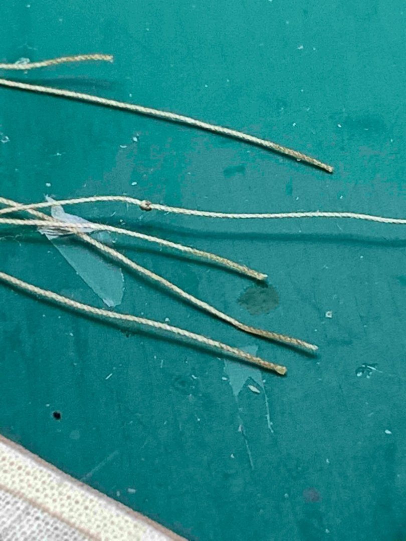
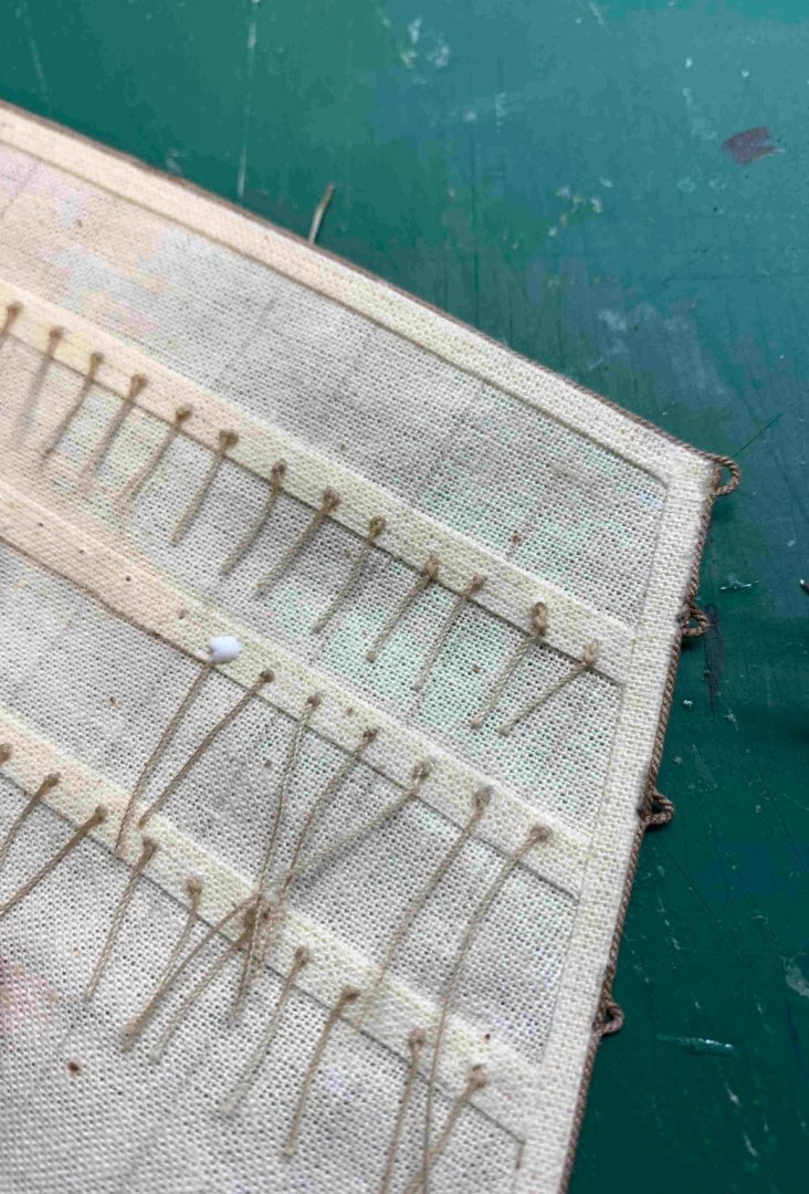
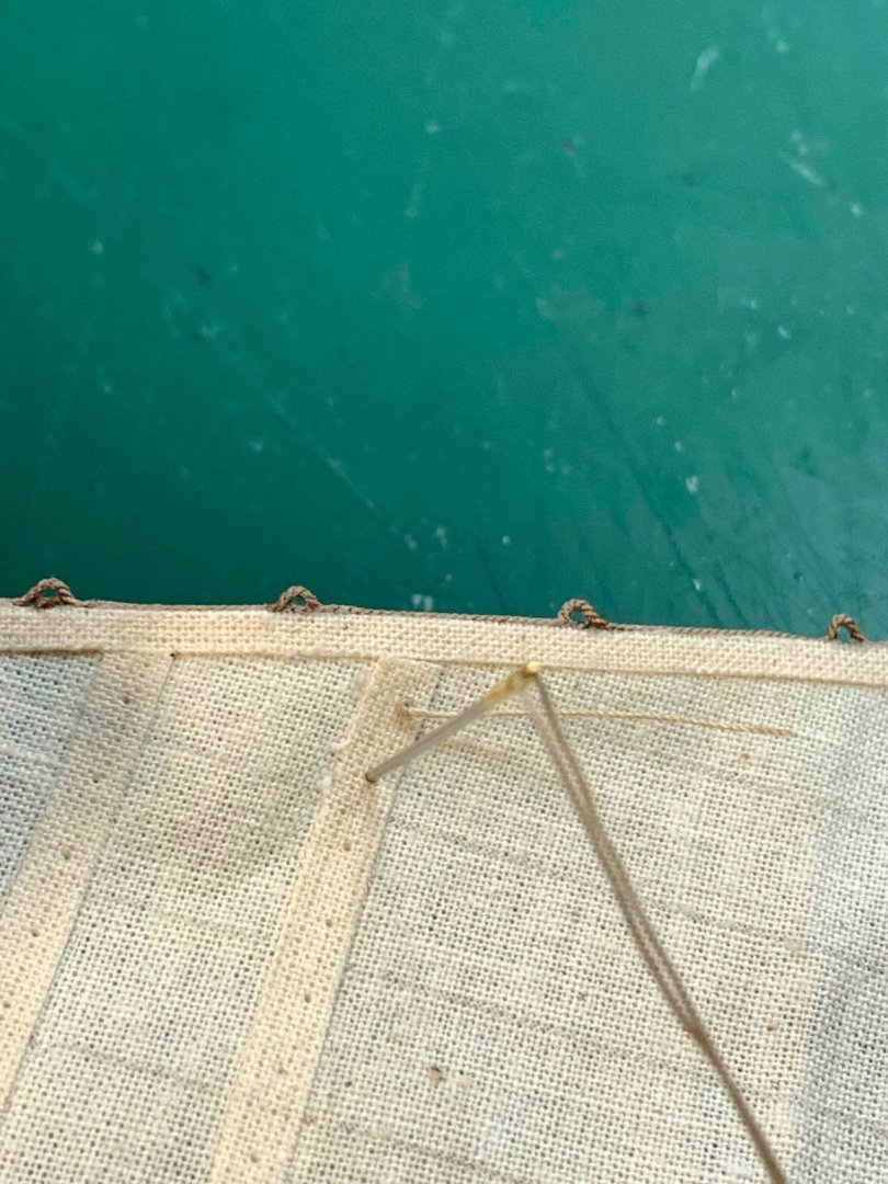
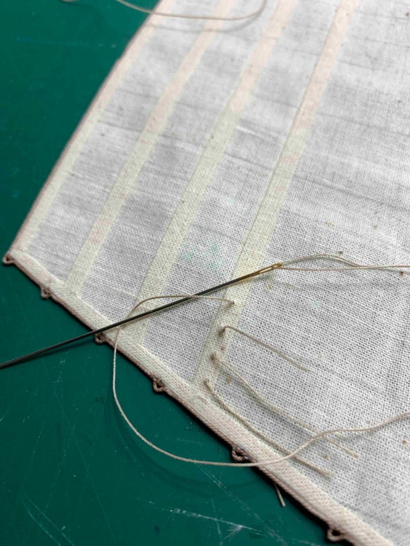
Reef points installation process.. Mark it on the sail.. The knot was made on one end of the rope.. With needle it will be pushed through the sail.. if the hole is big enough, the reef line can be frozen with CA glue on one end and that end can be pushed thru the hole... this way no need for needle.. On the other side of the sail, the another knot was made.. The string is pooled and the knot was finished on the sail.. The knots were frozen with a drop of diluted PVA glue on each knot.. and dried with the hot gun (on lowest heat setting)... Haircut time.. One row is completed.. Happy modelling...


- 275 replies
-
- 2
-
-
- phoenix
- master korabel
- (and 1 more)
-
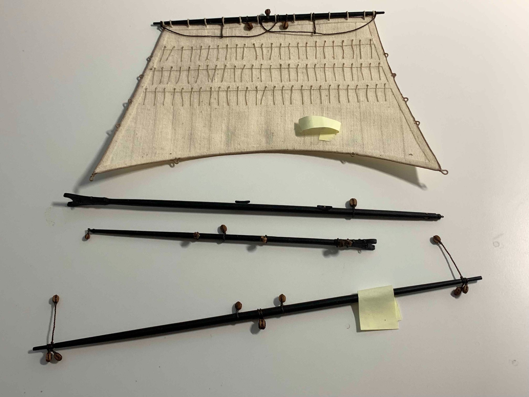
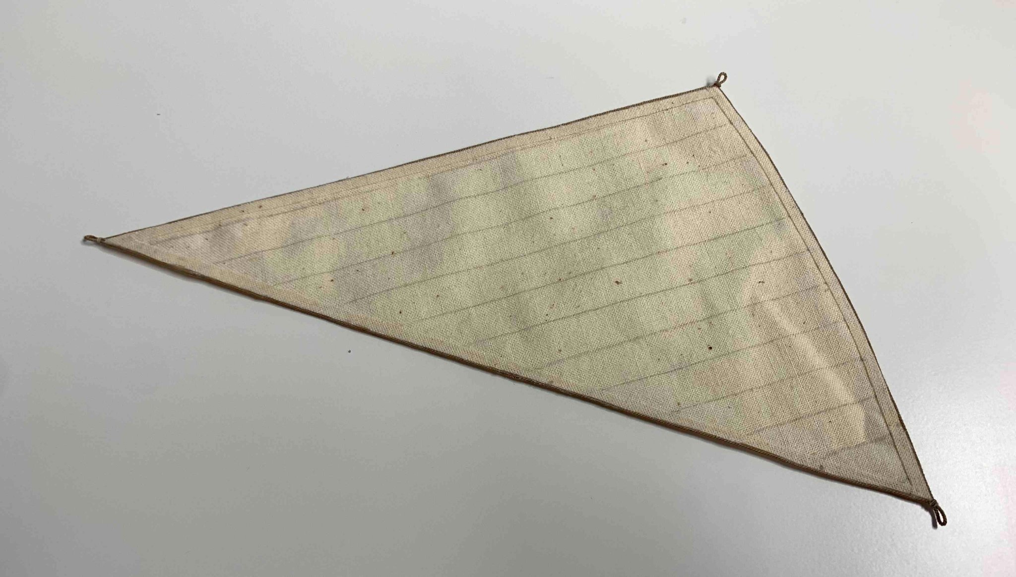
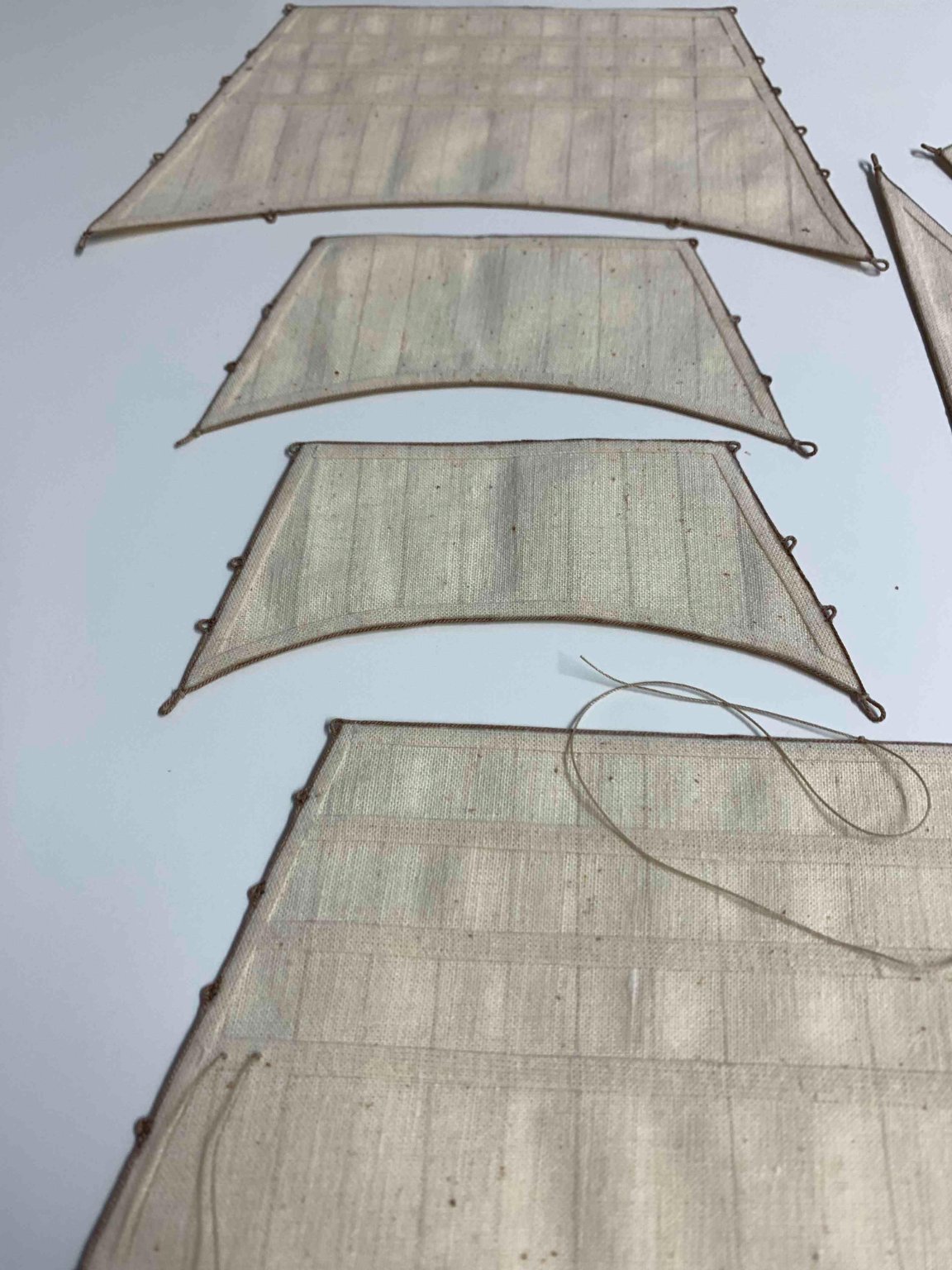
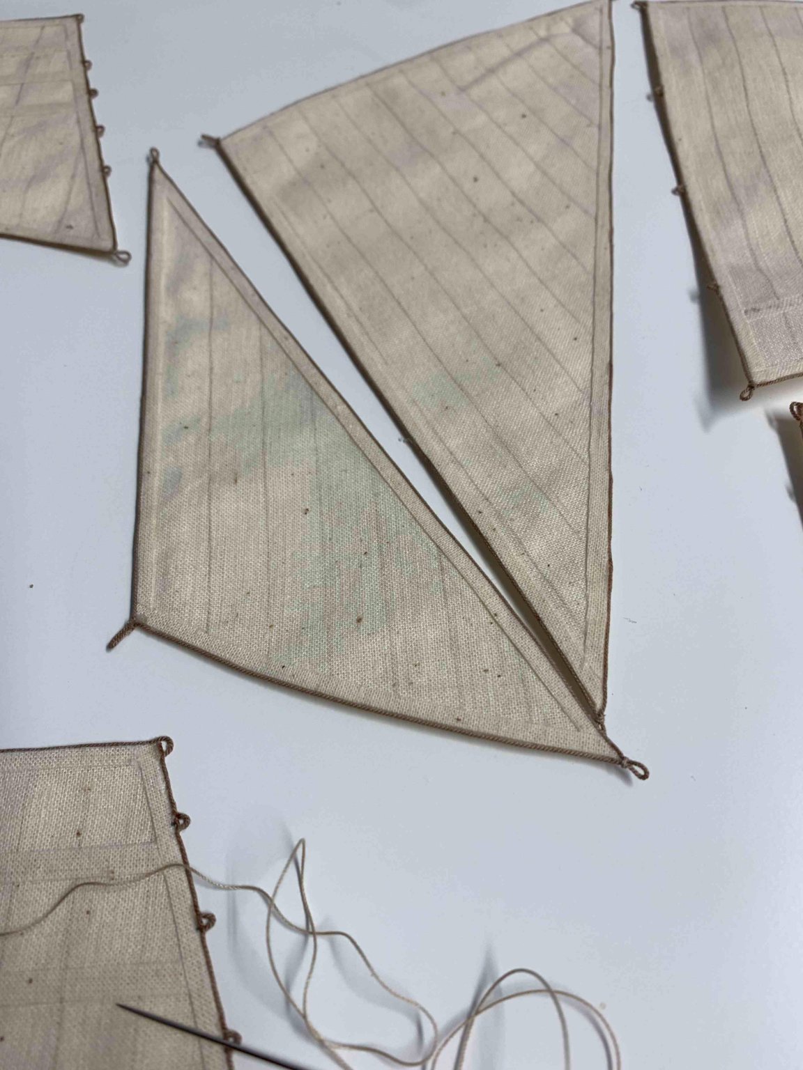
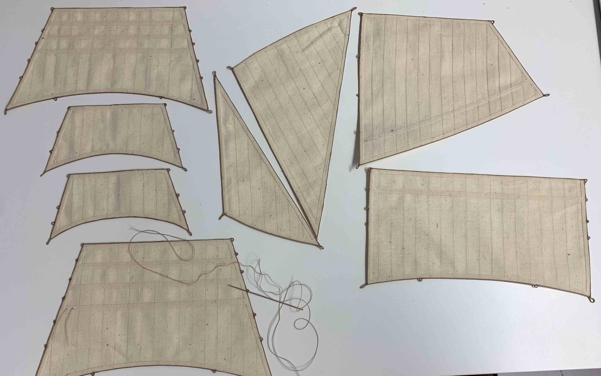
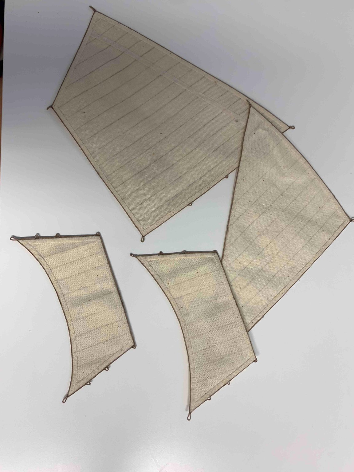
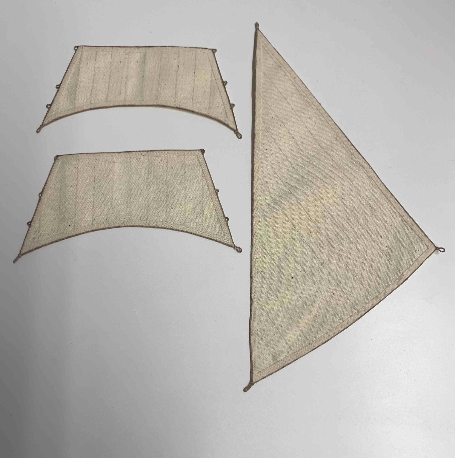
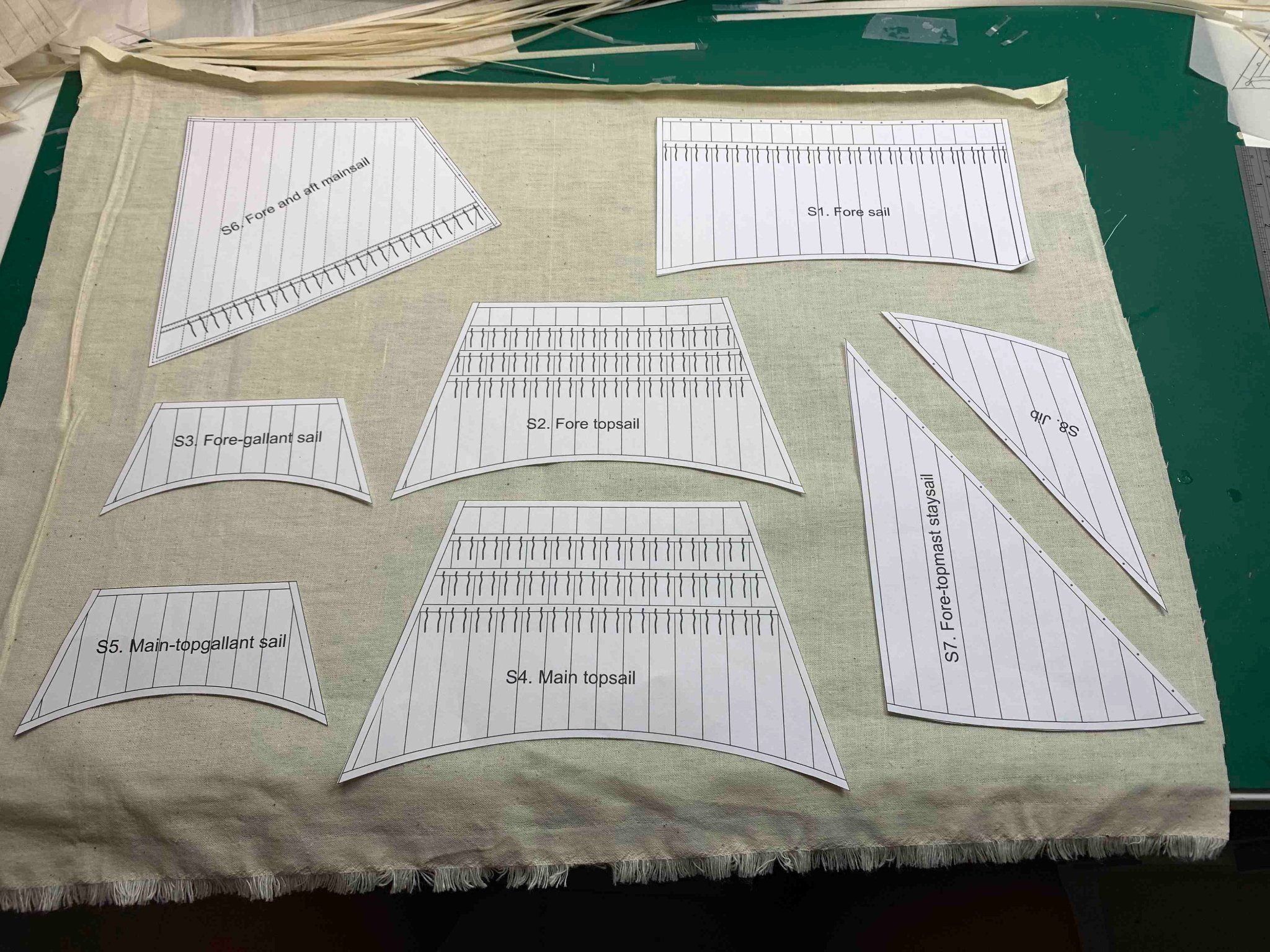
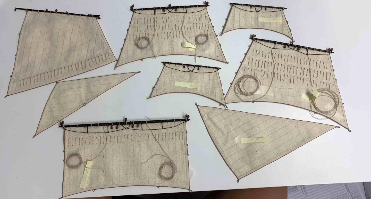
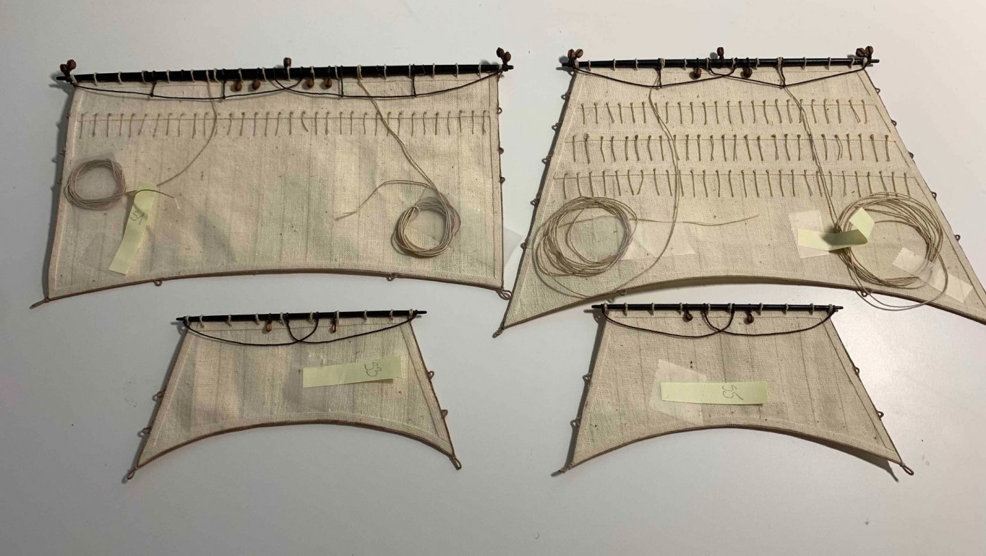
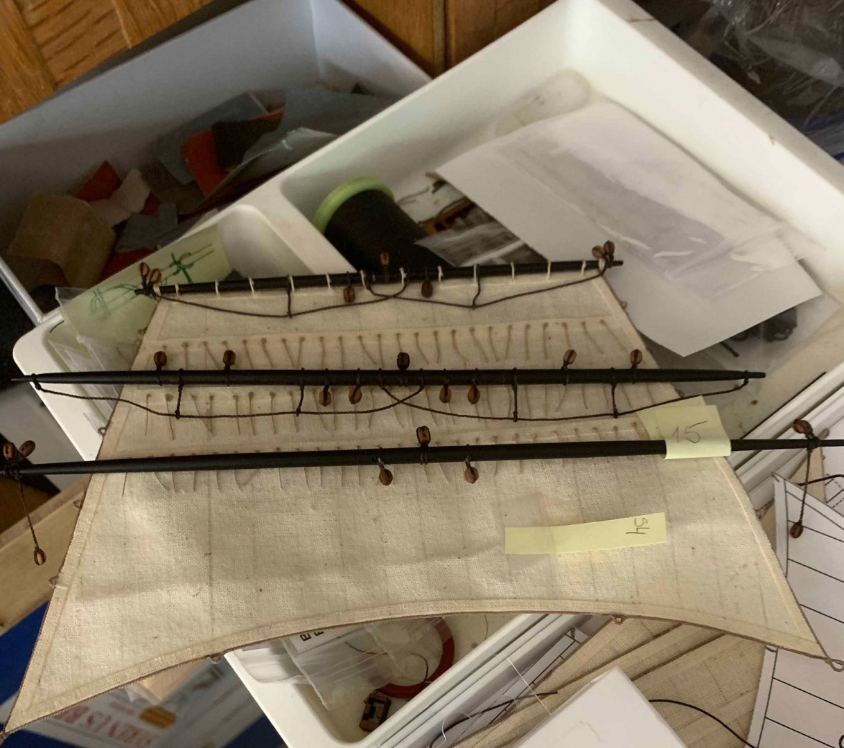
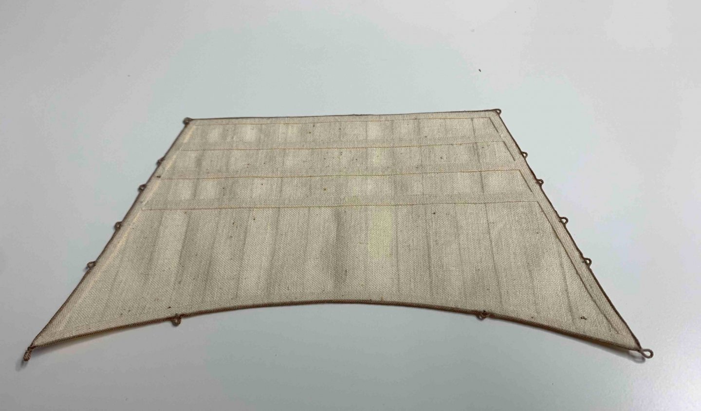
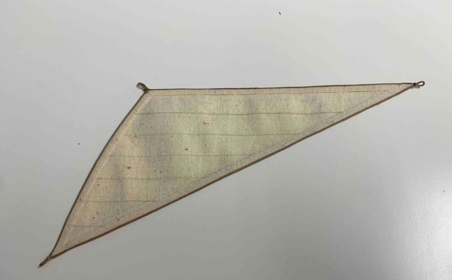
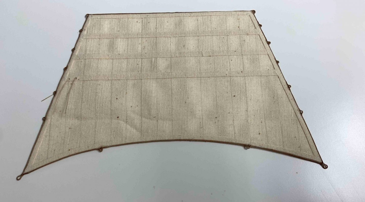
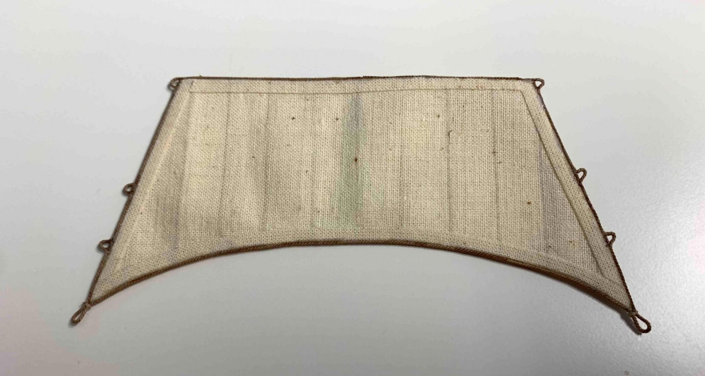
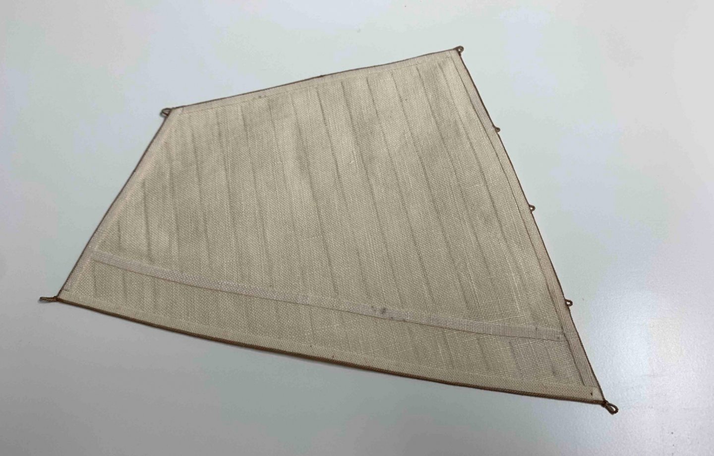
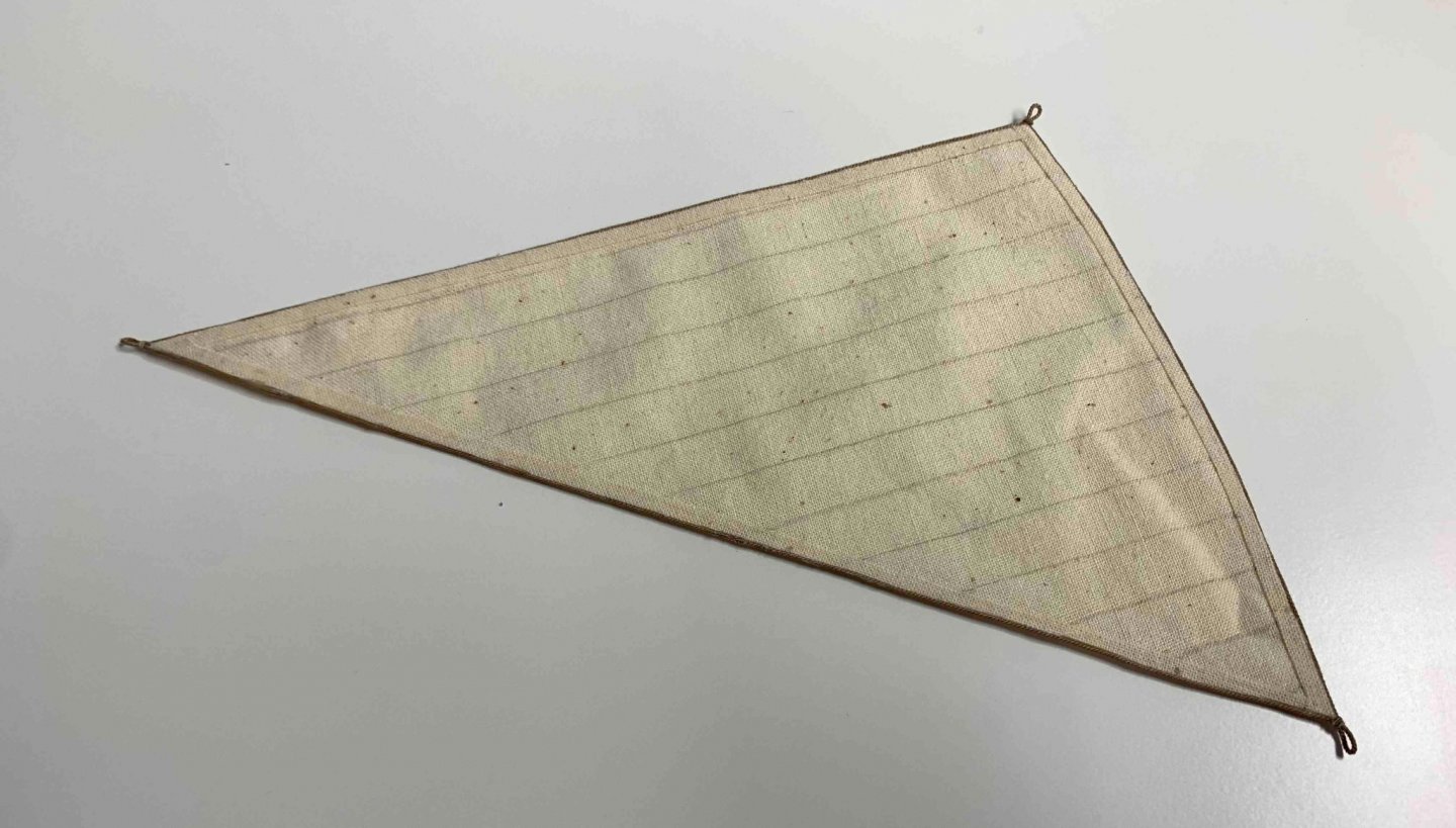
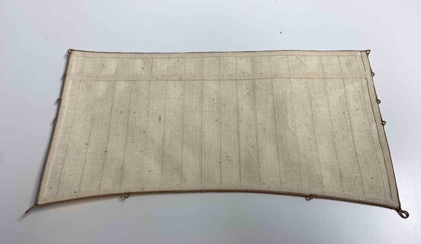
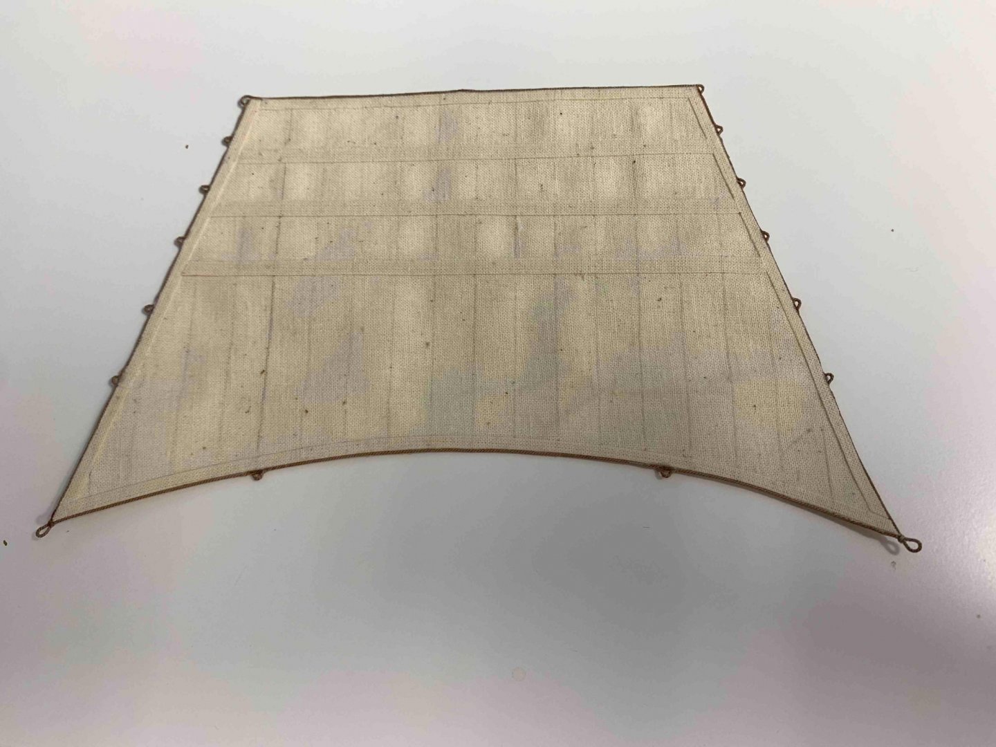
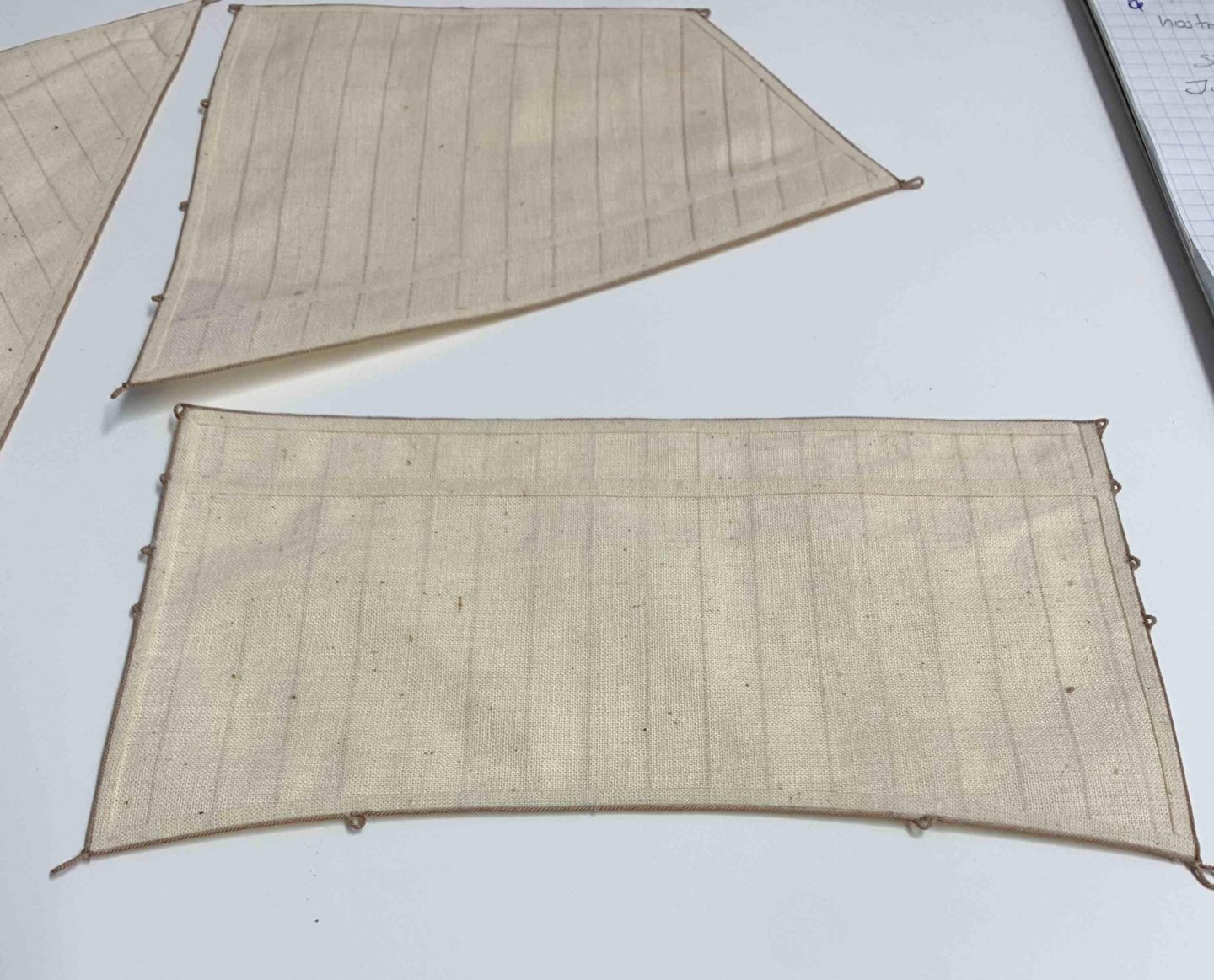
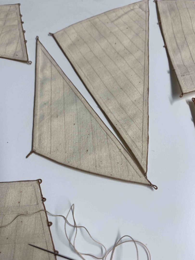
First part of making sail is completed. Fore topsail.. Jib.. Main topsail.. with few reef points ... Fore-gallant sail... Main-topgallant sail... Fore and aft mainsail... Fore -topmast staysail... Fore sail.. Happy modelling...


-
Few more pictures... Template... Happy modelling...


-
A bit of a progress.. Happy modelling.


-
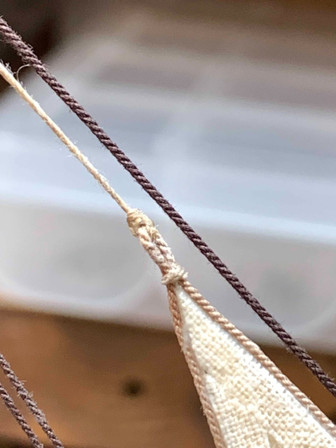
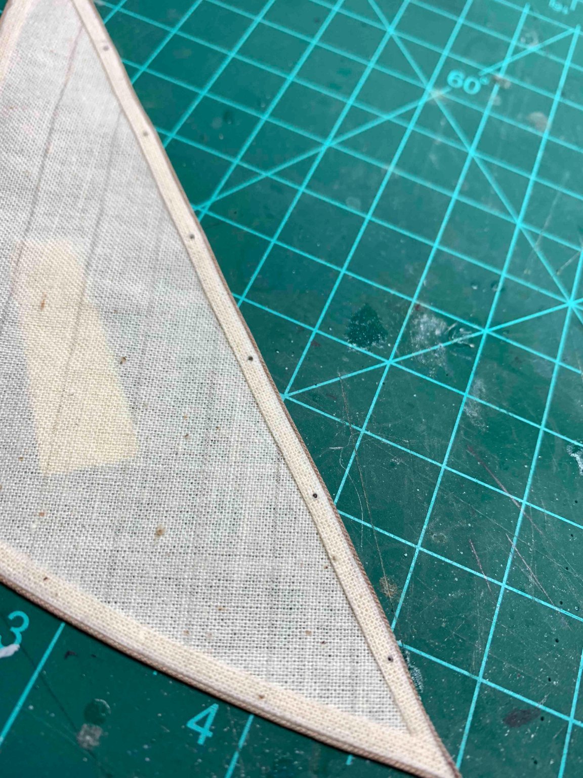
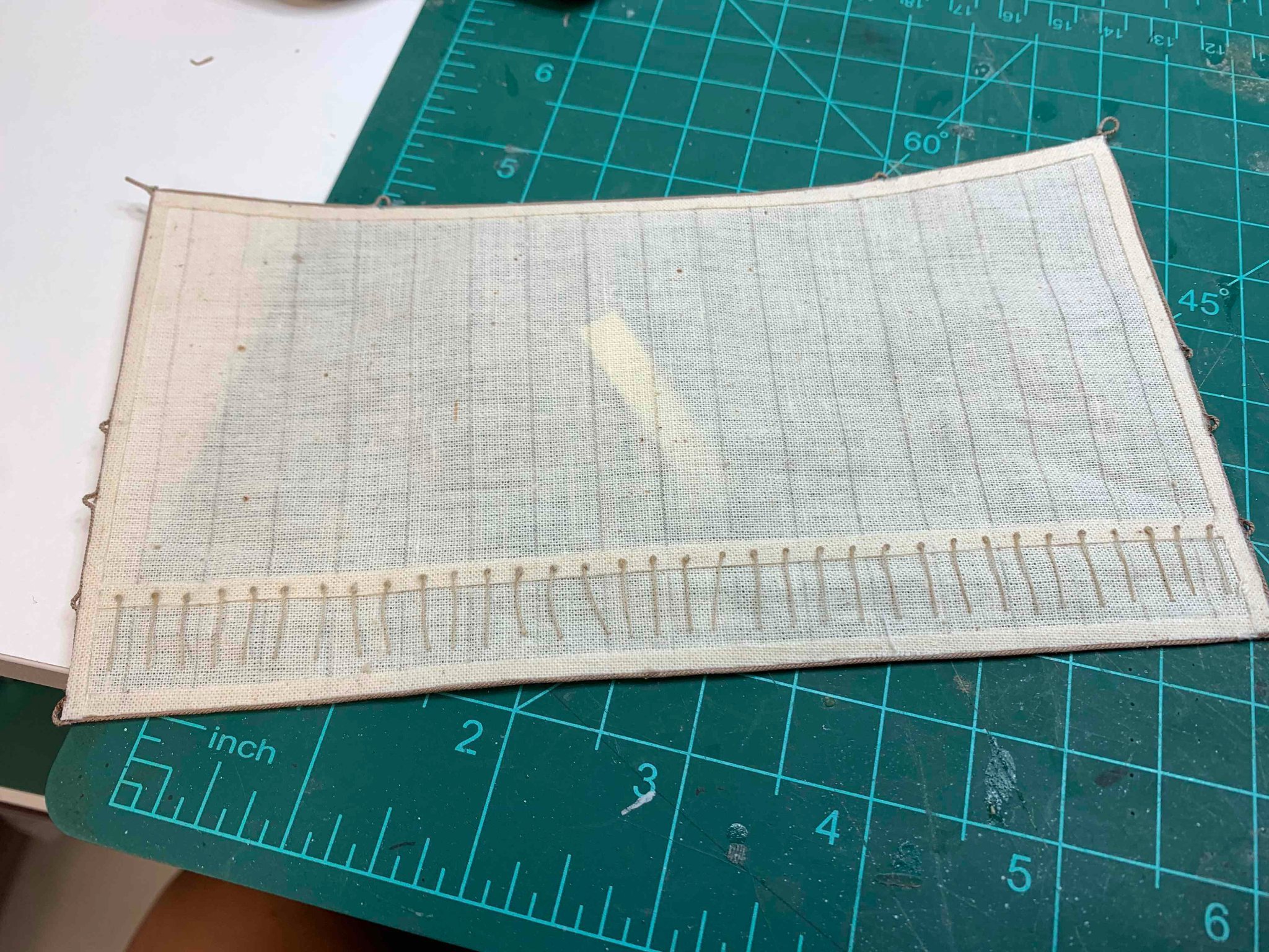
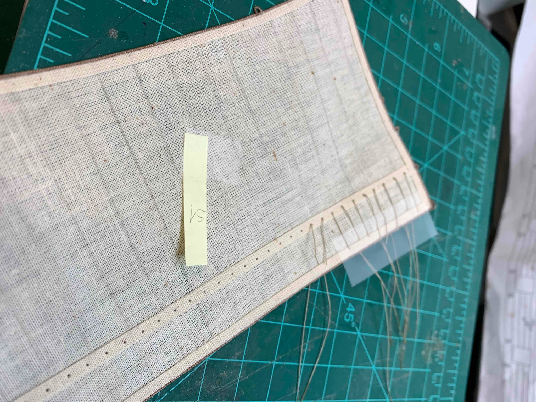
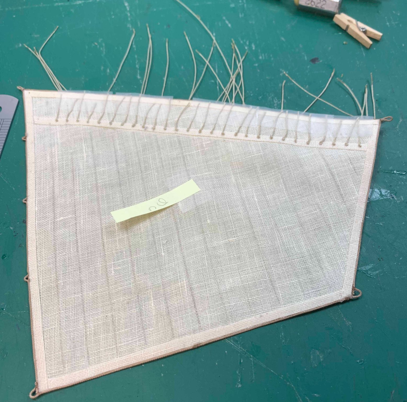
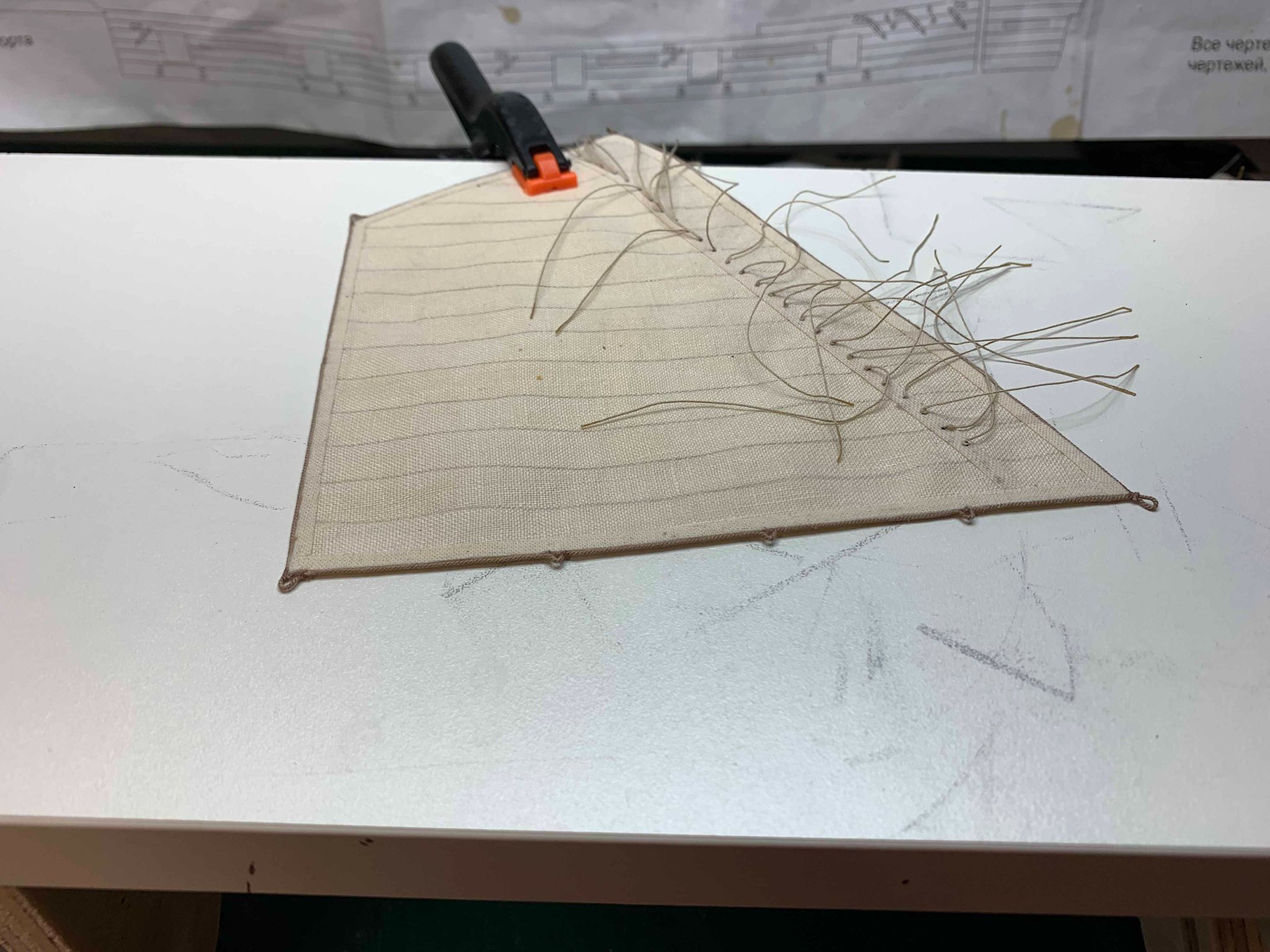
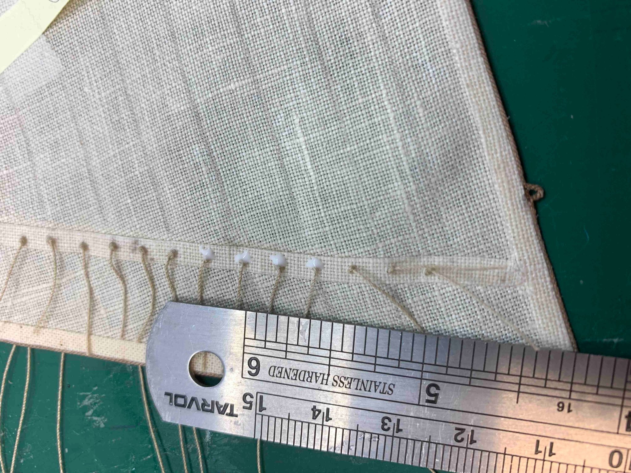
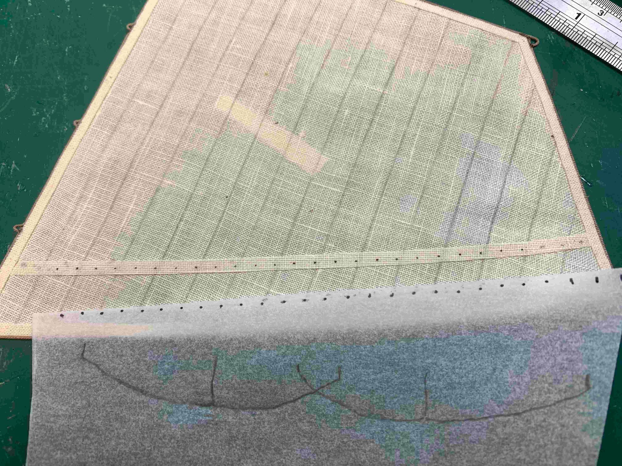
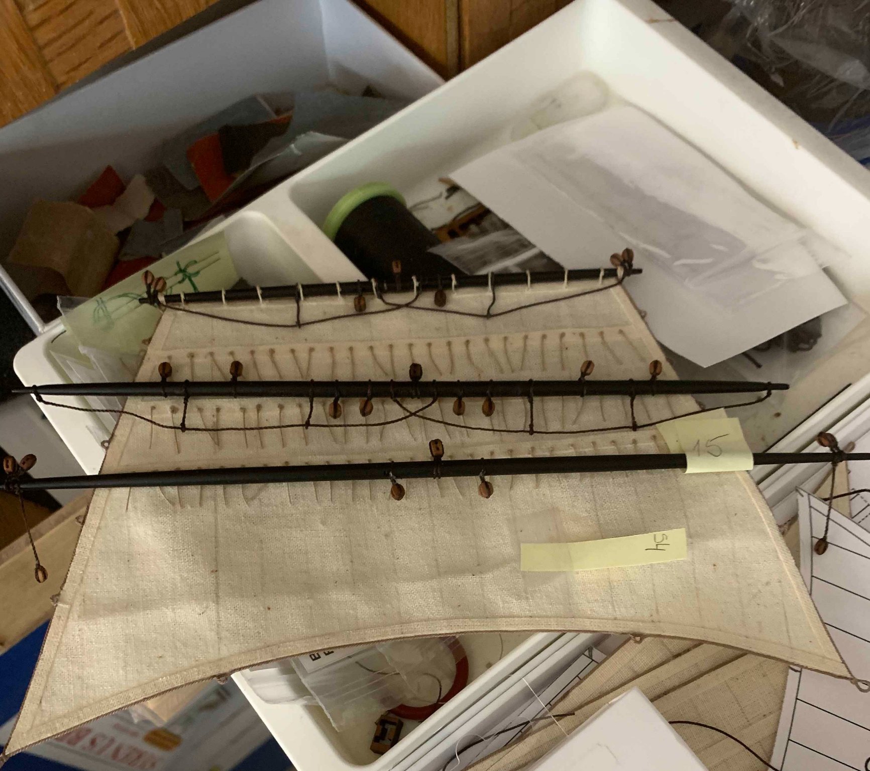
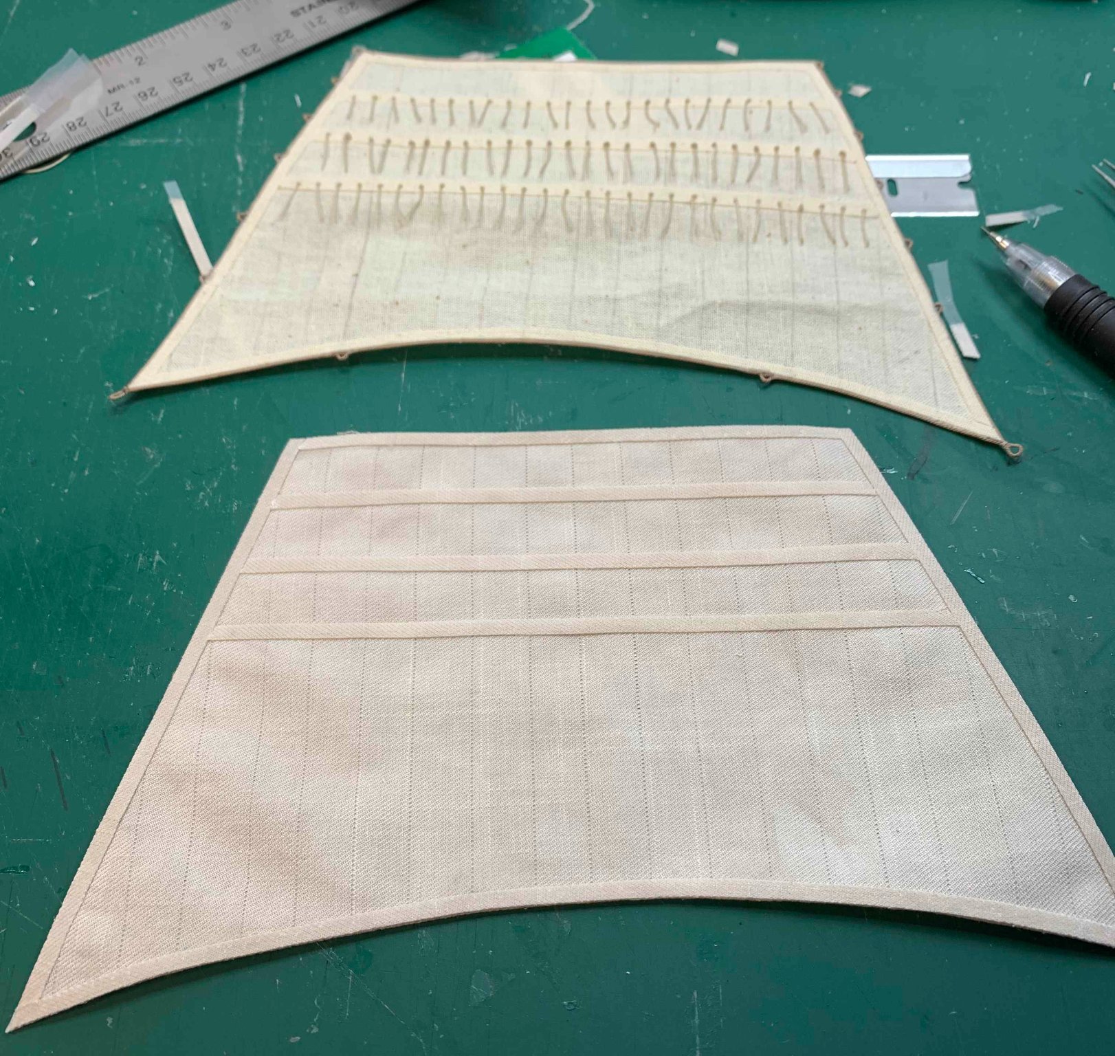
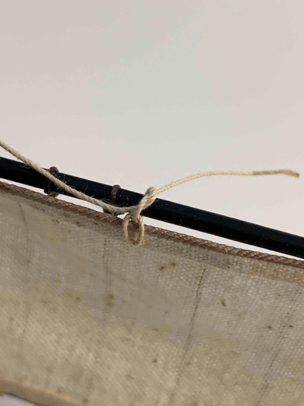
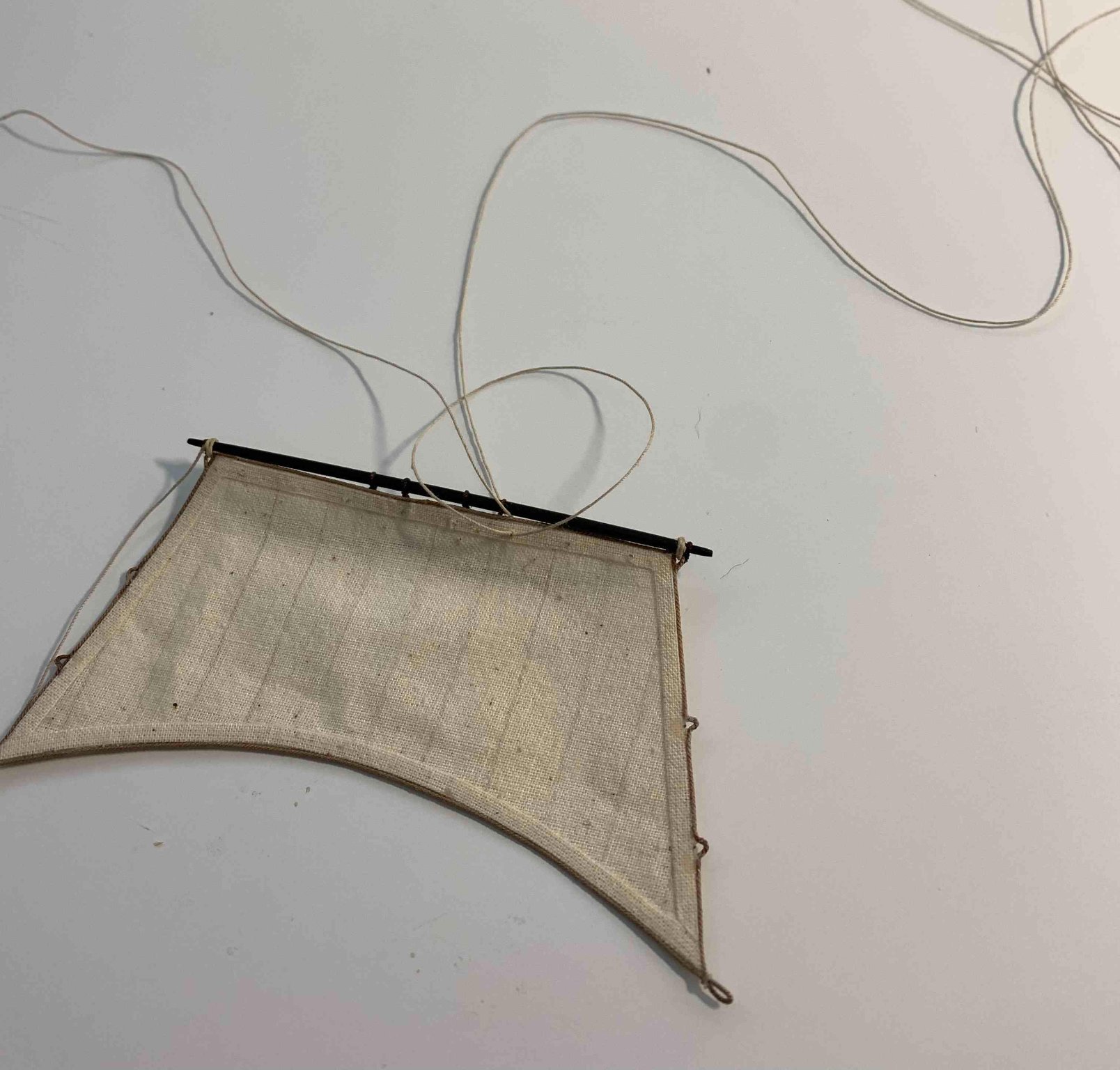
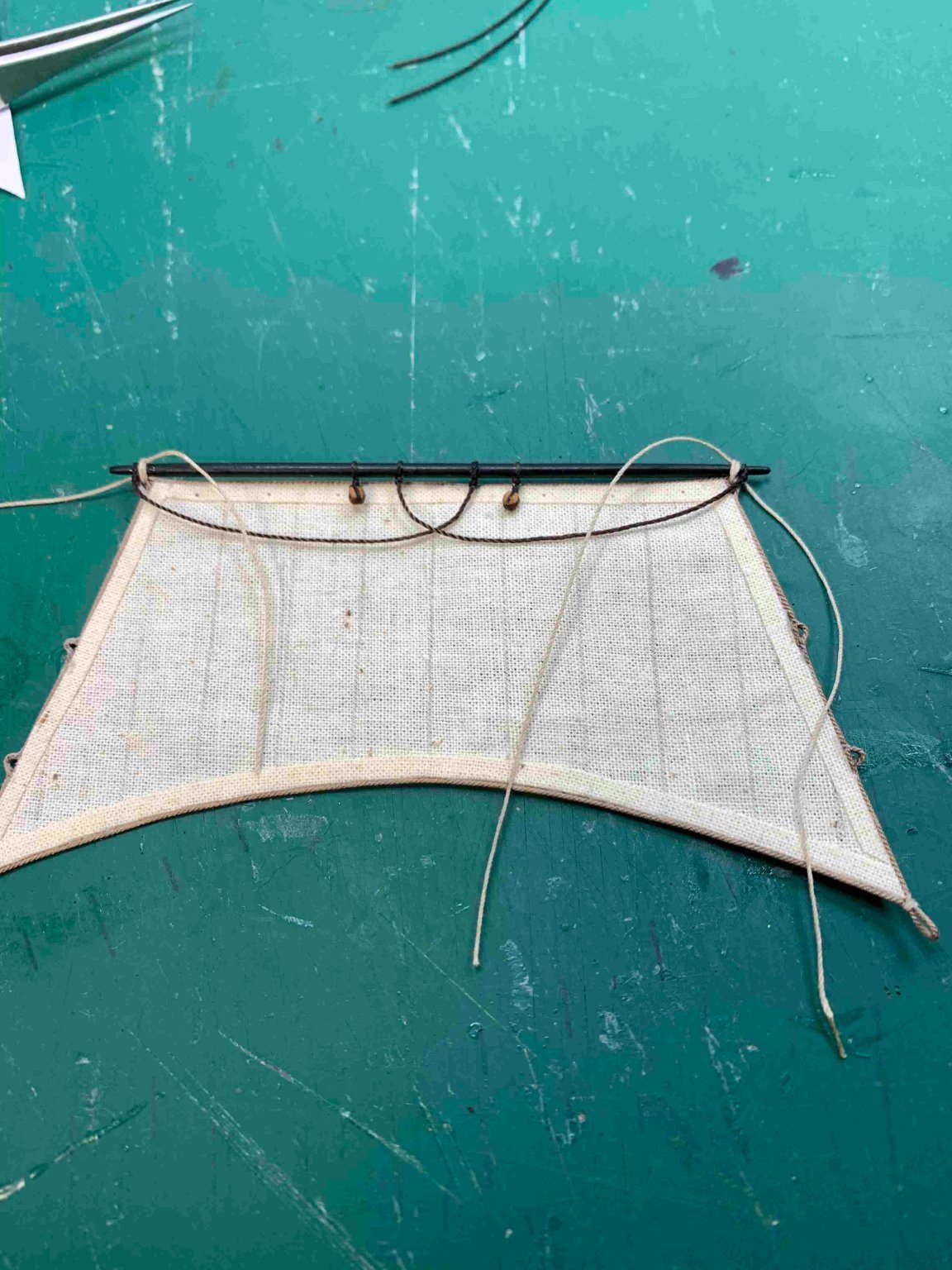
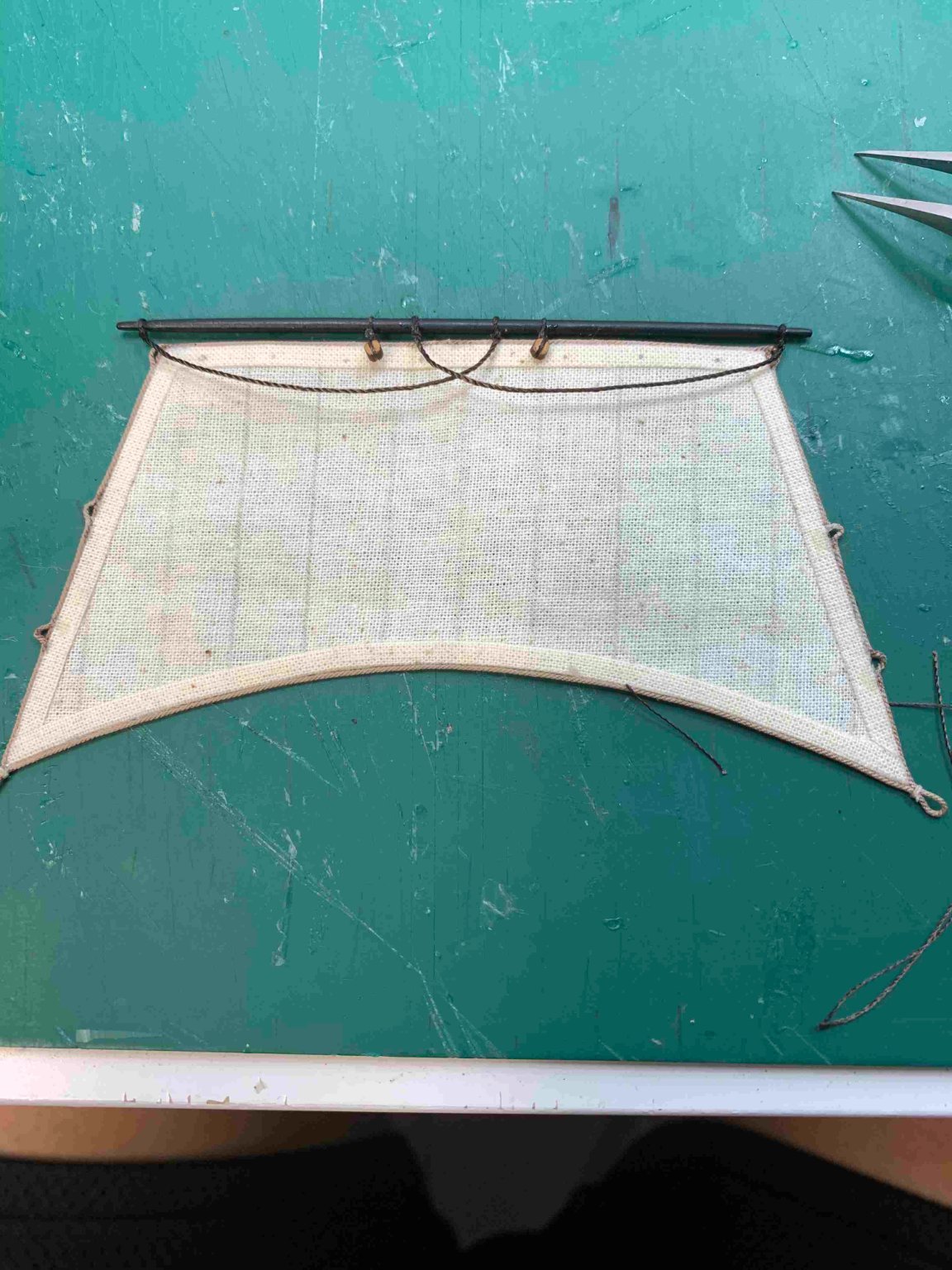
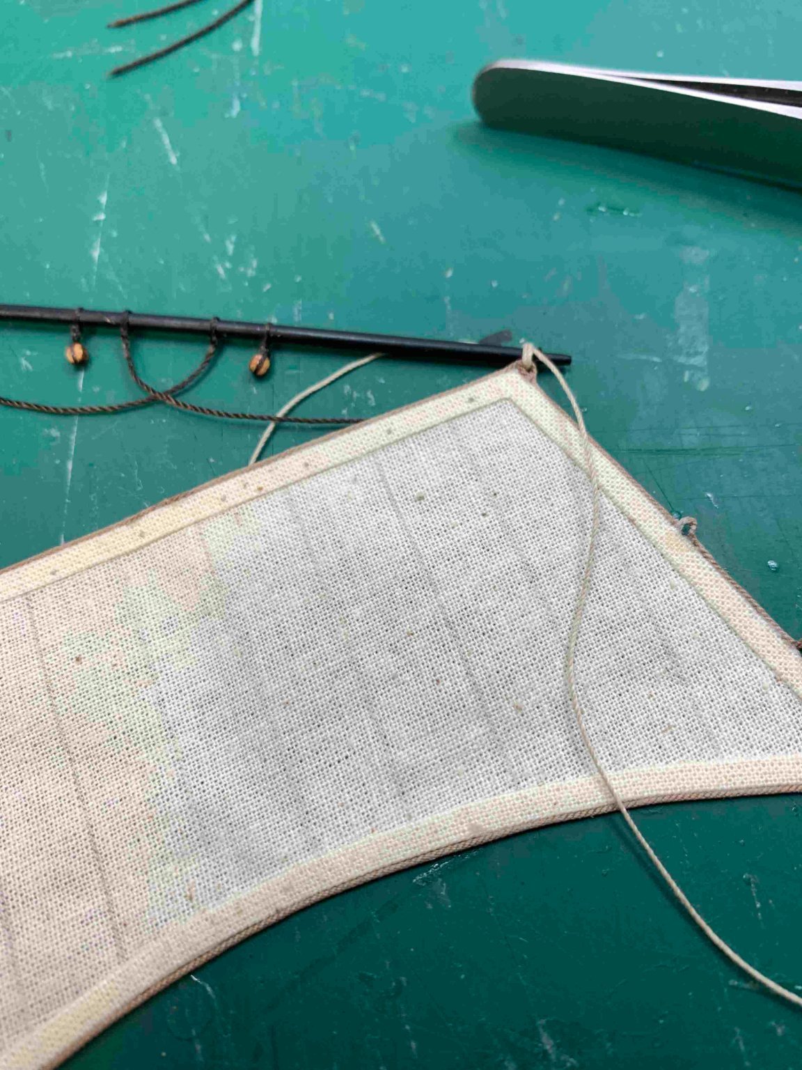
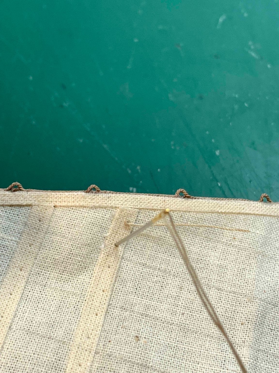
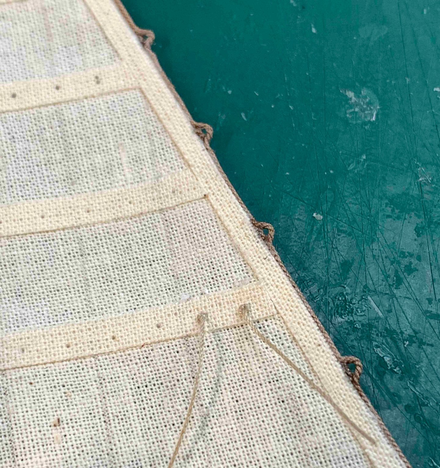
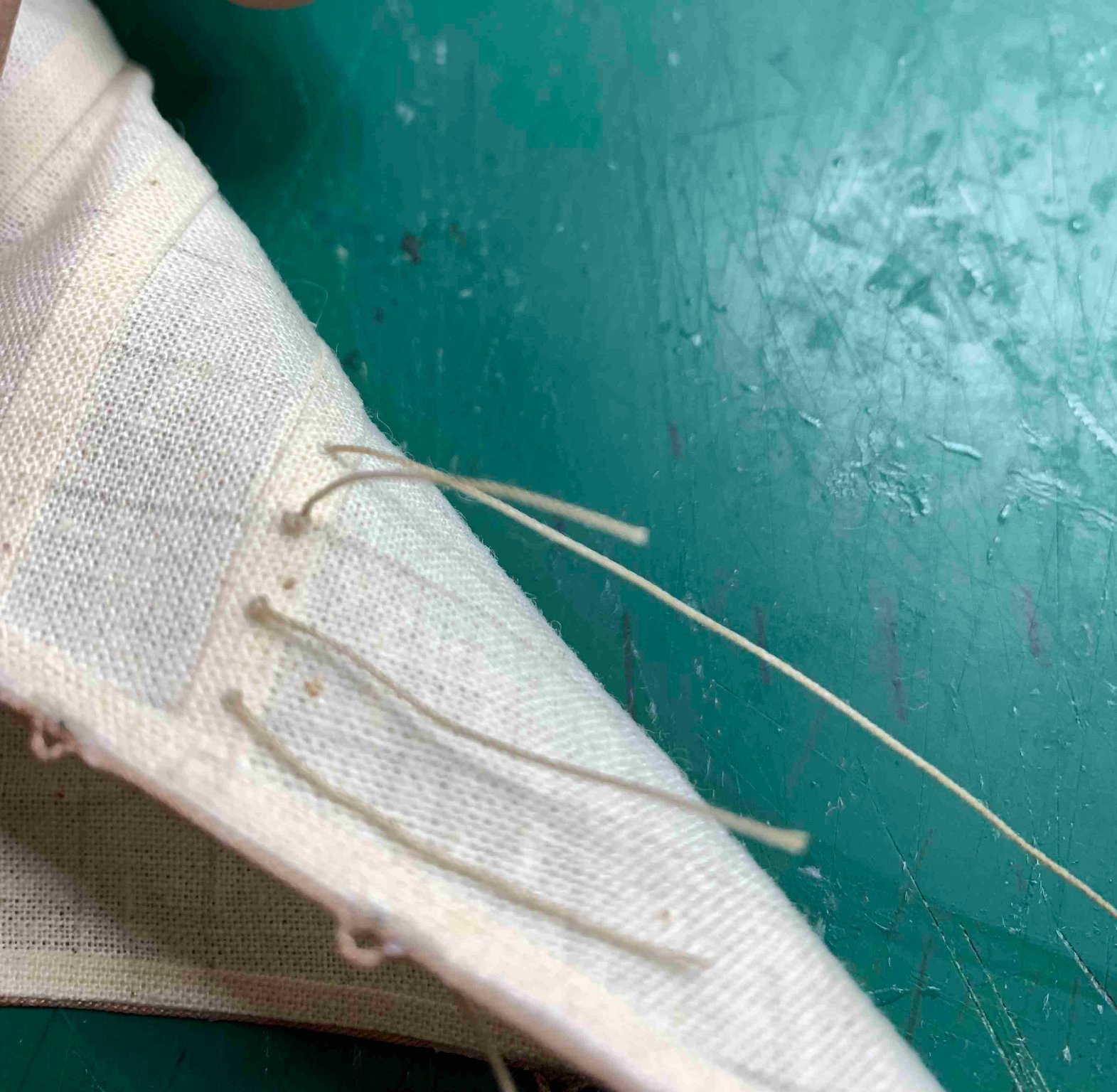
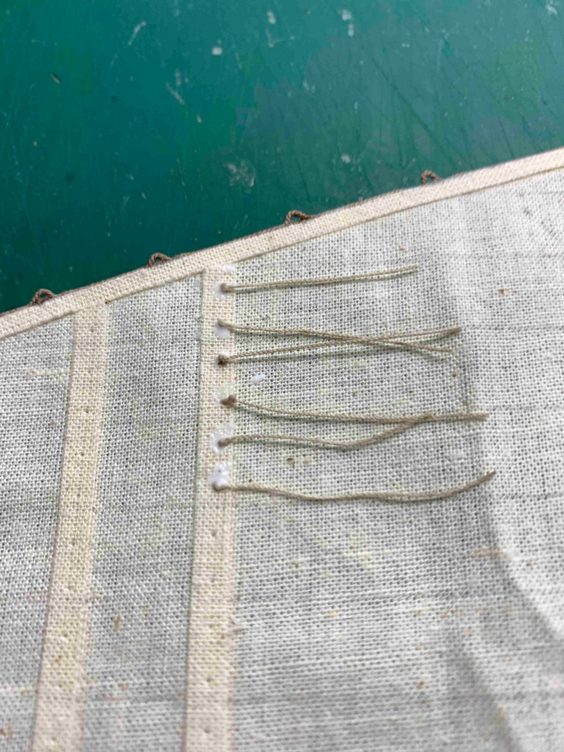
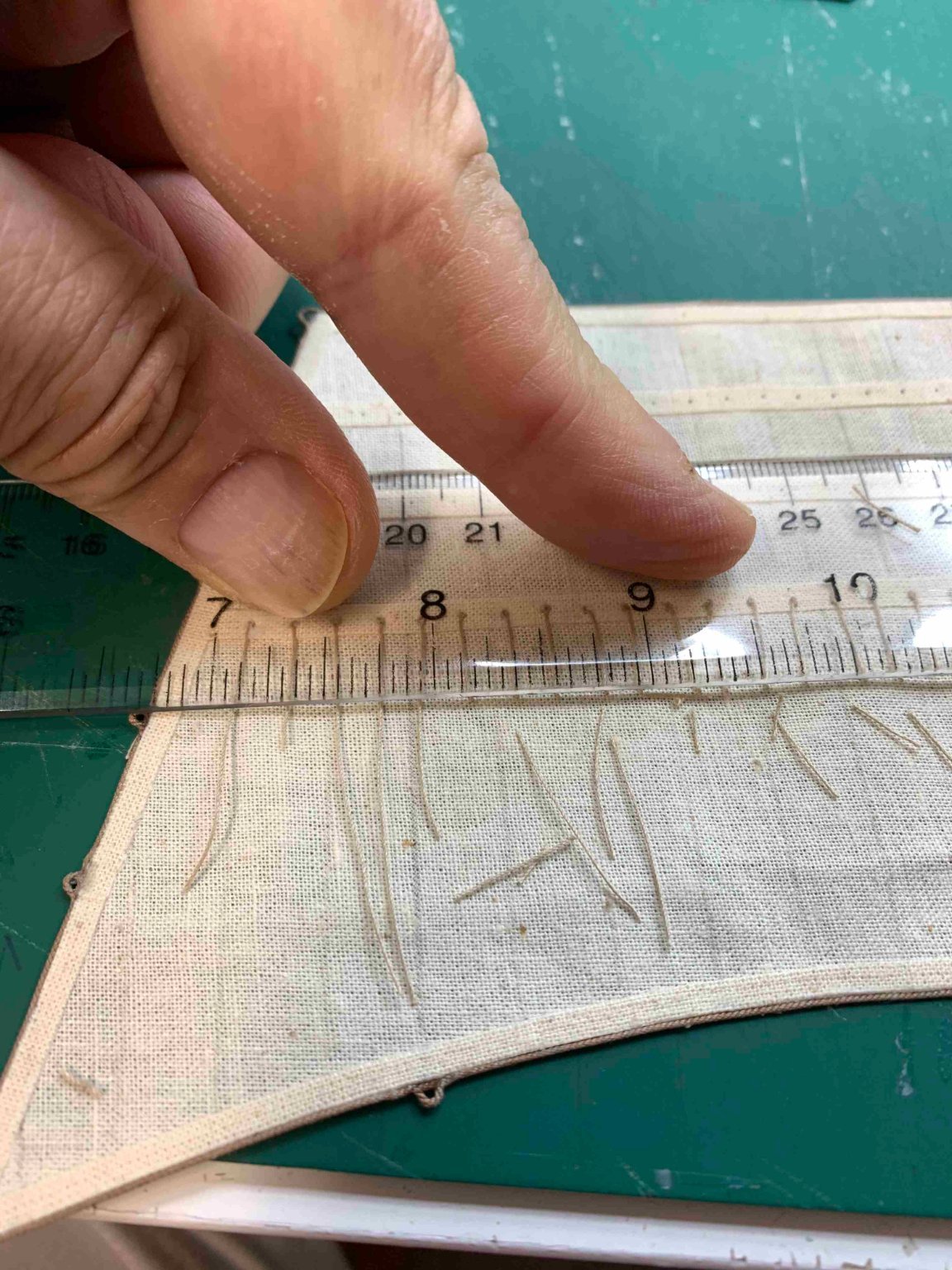
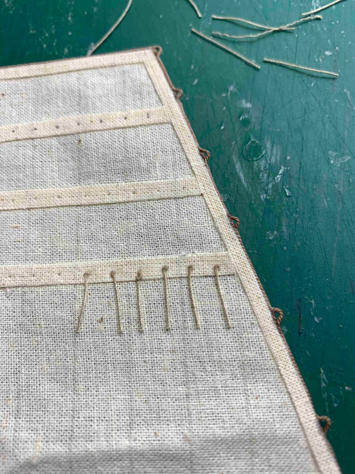
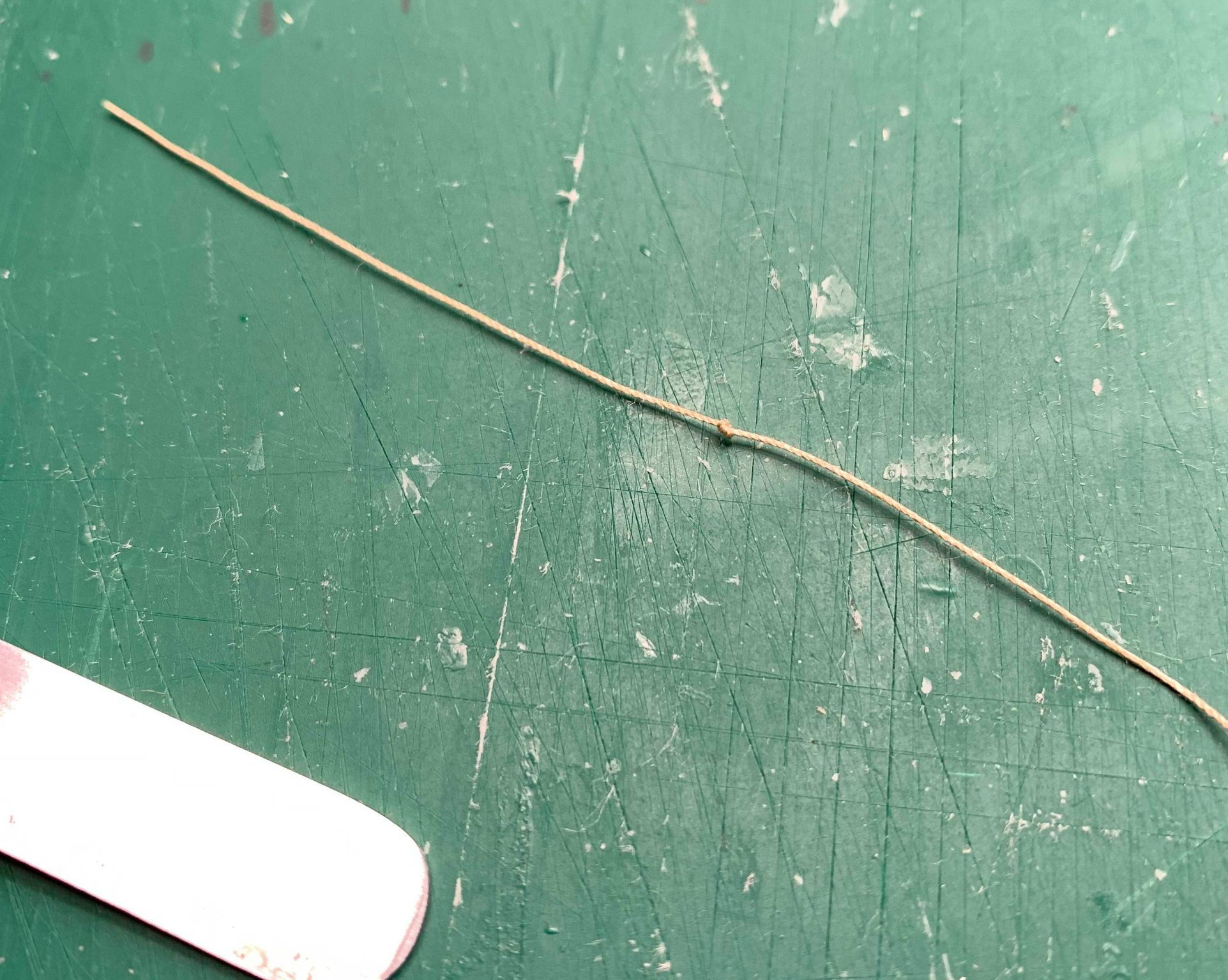
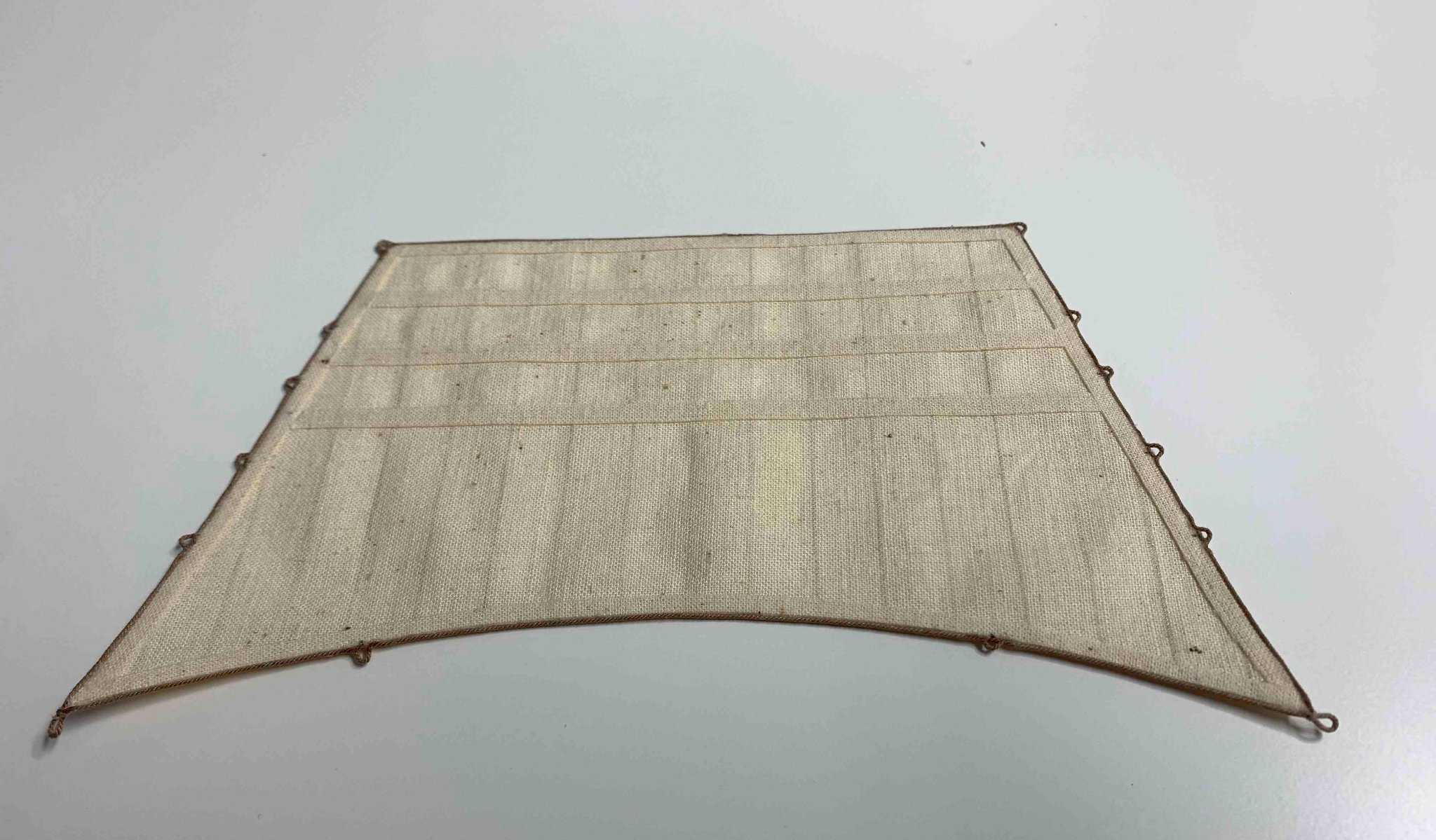
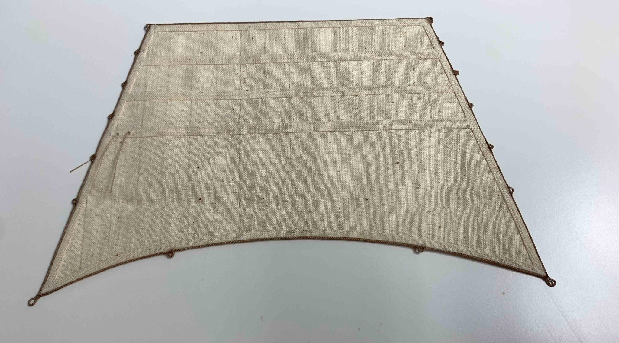
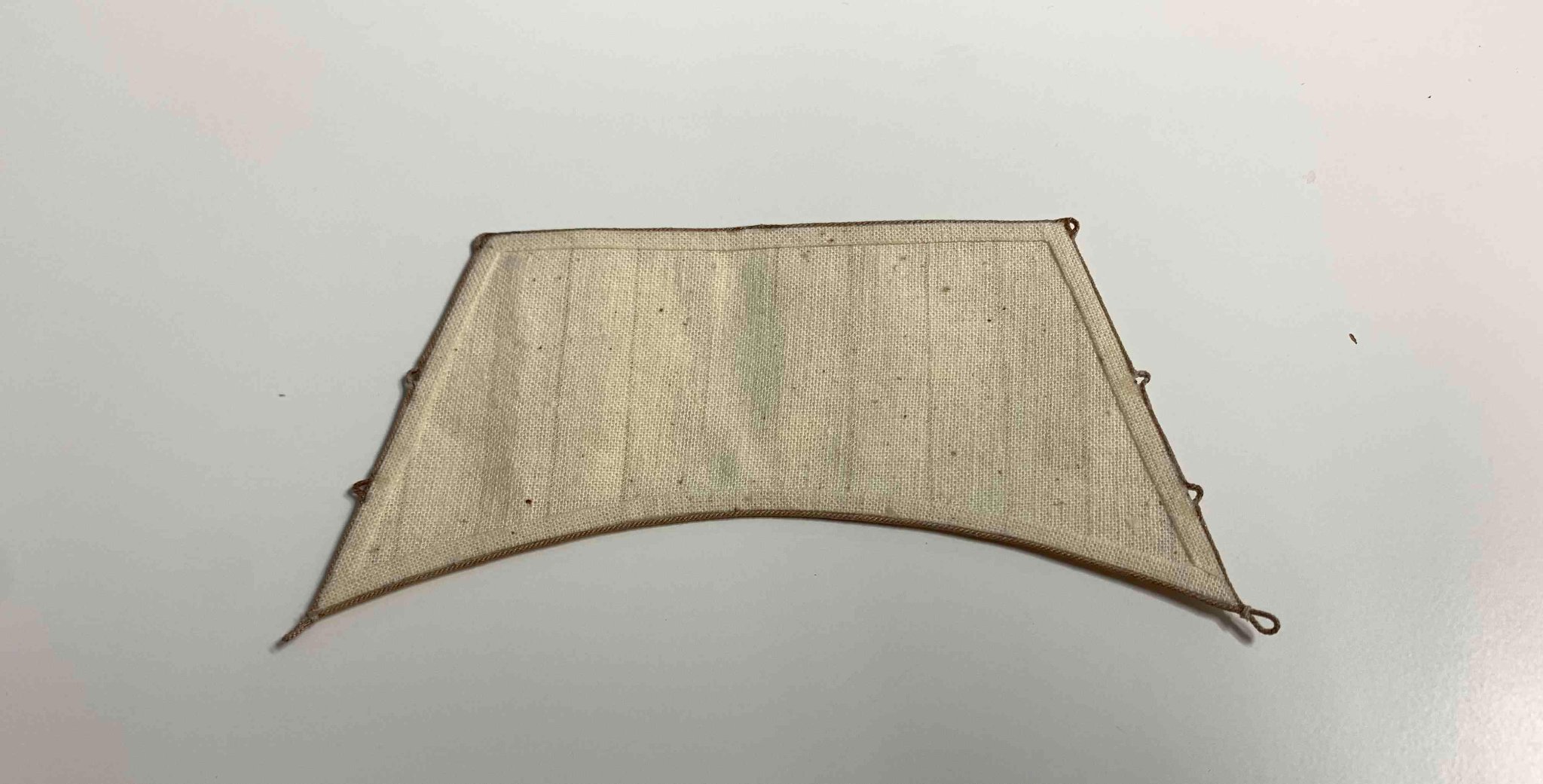
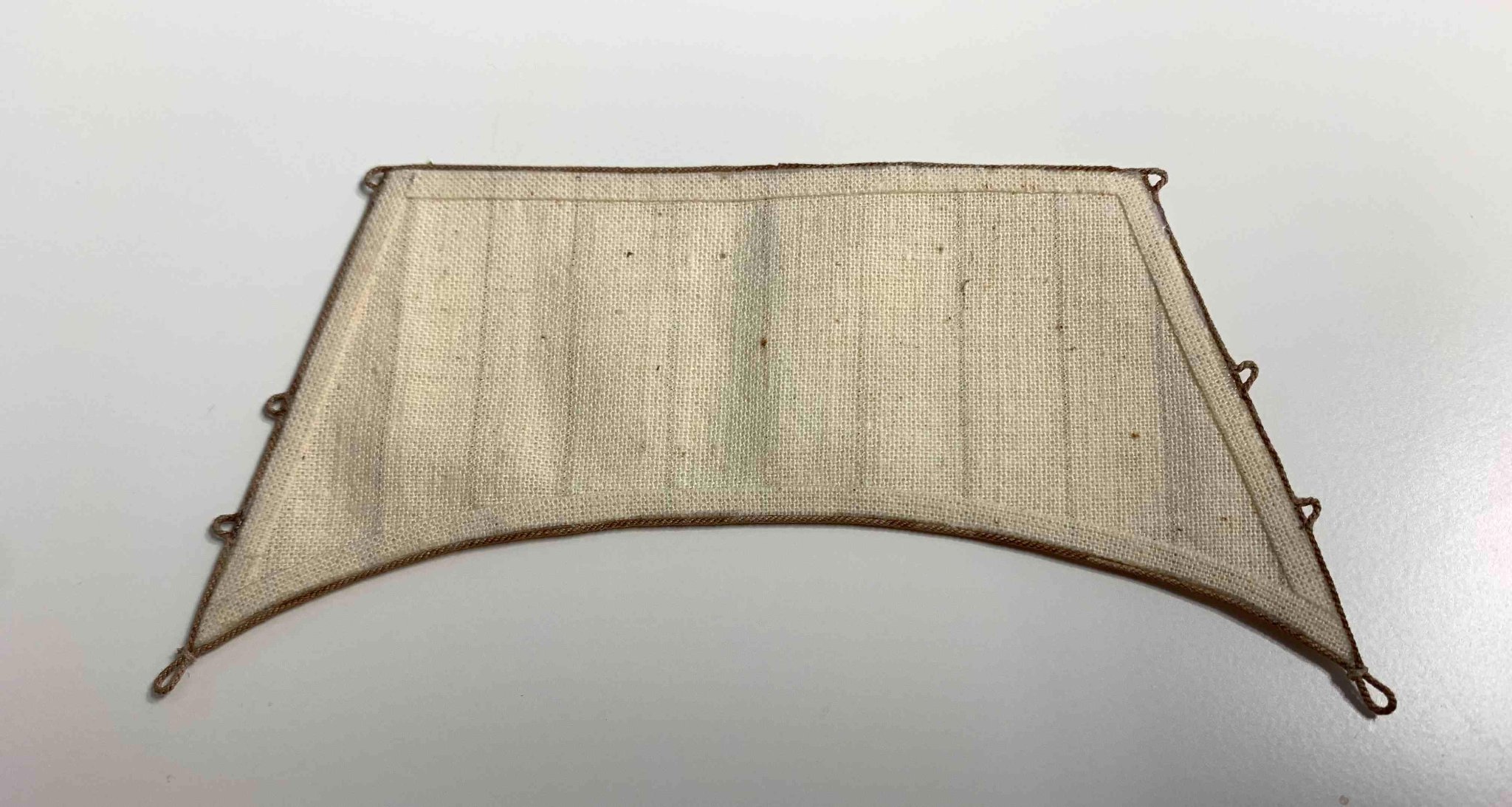
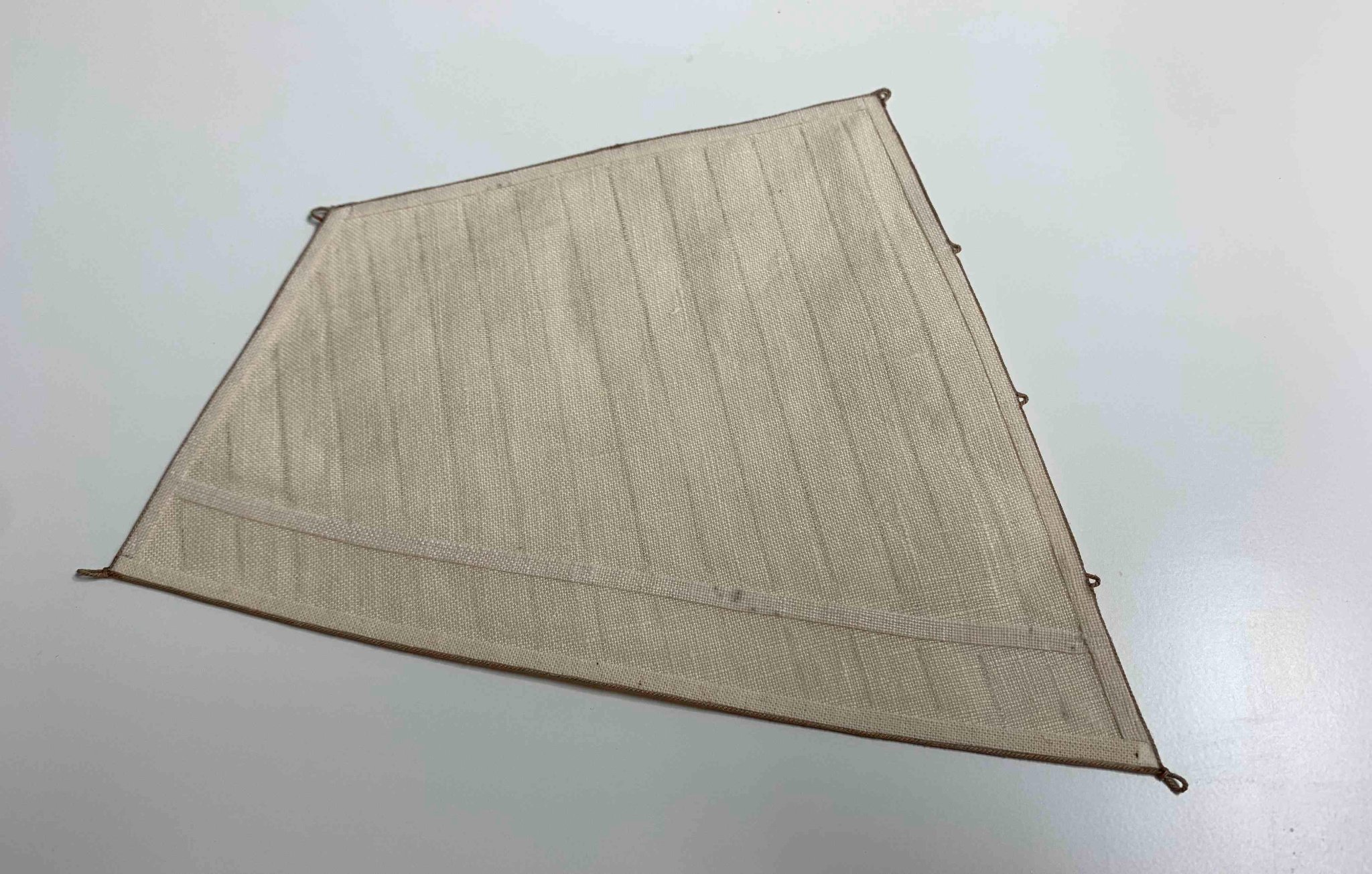
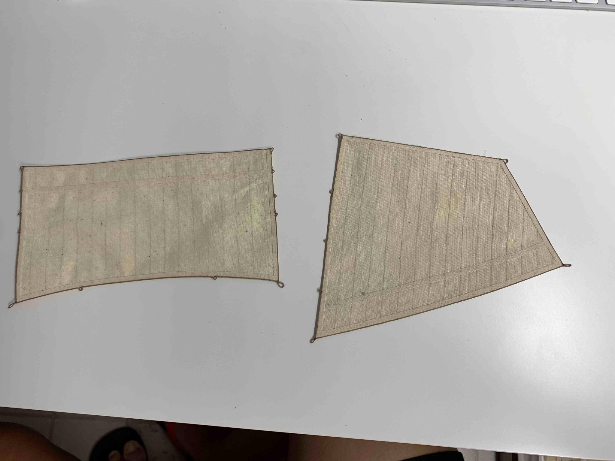
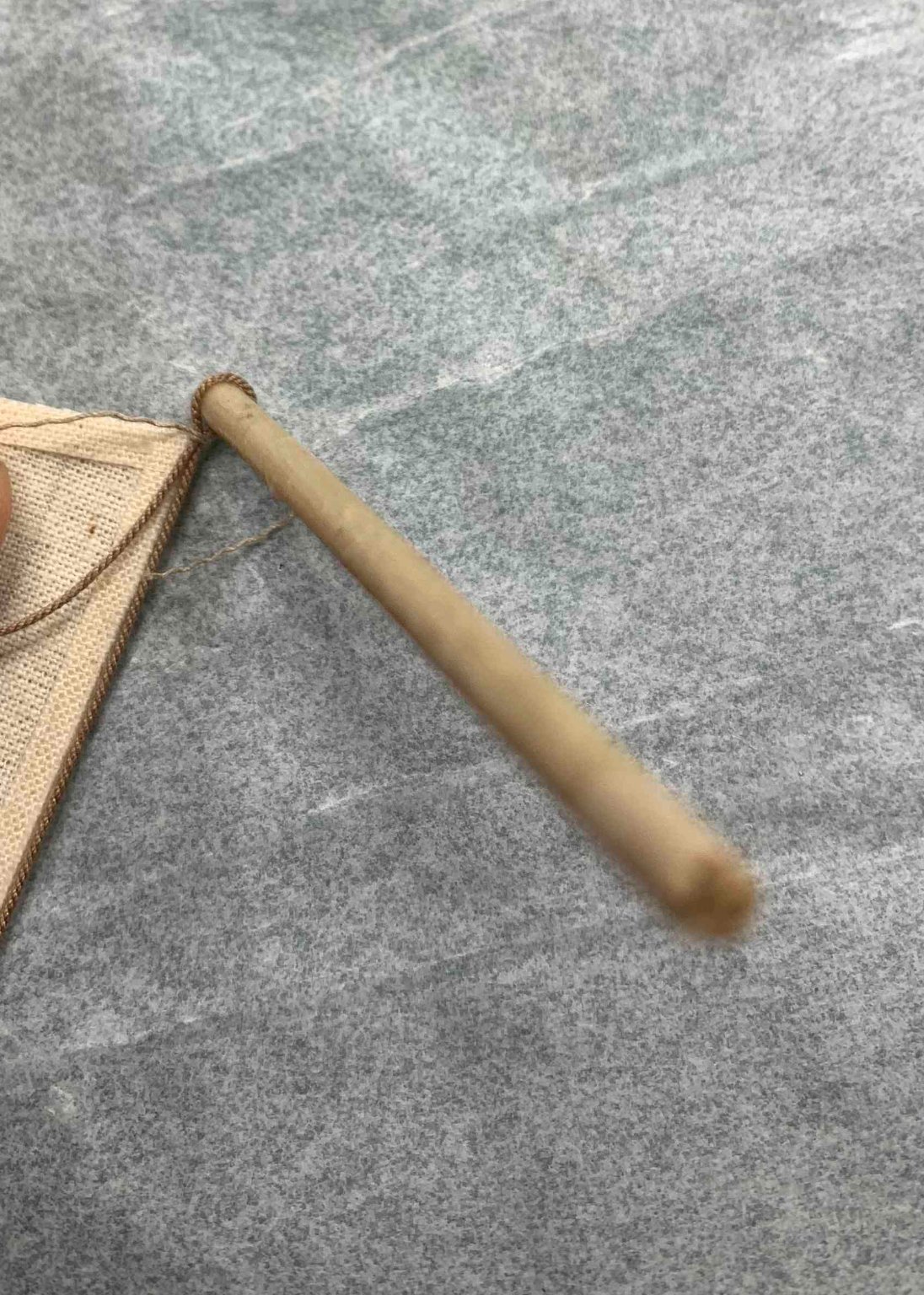
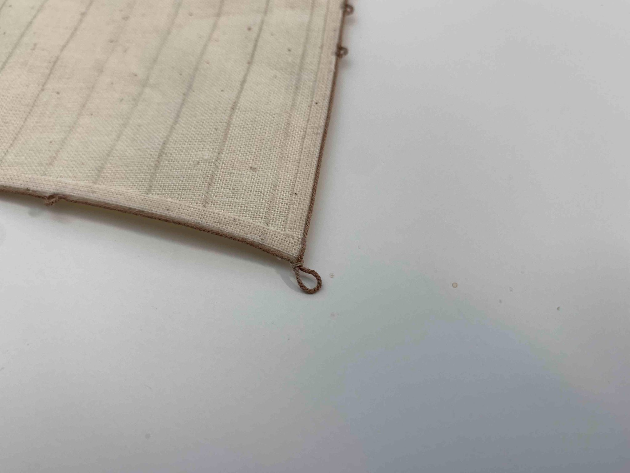
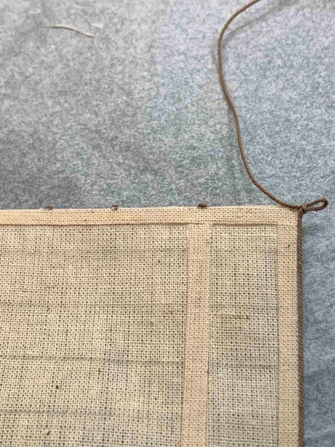
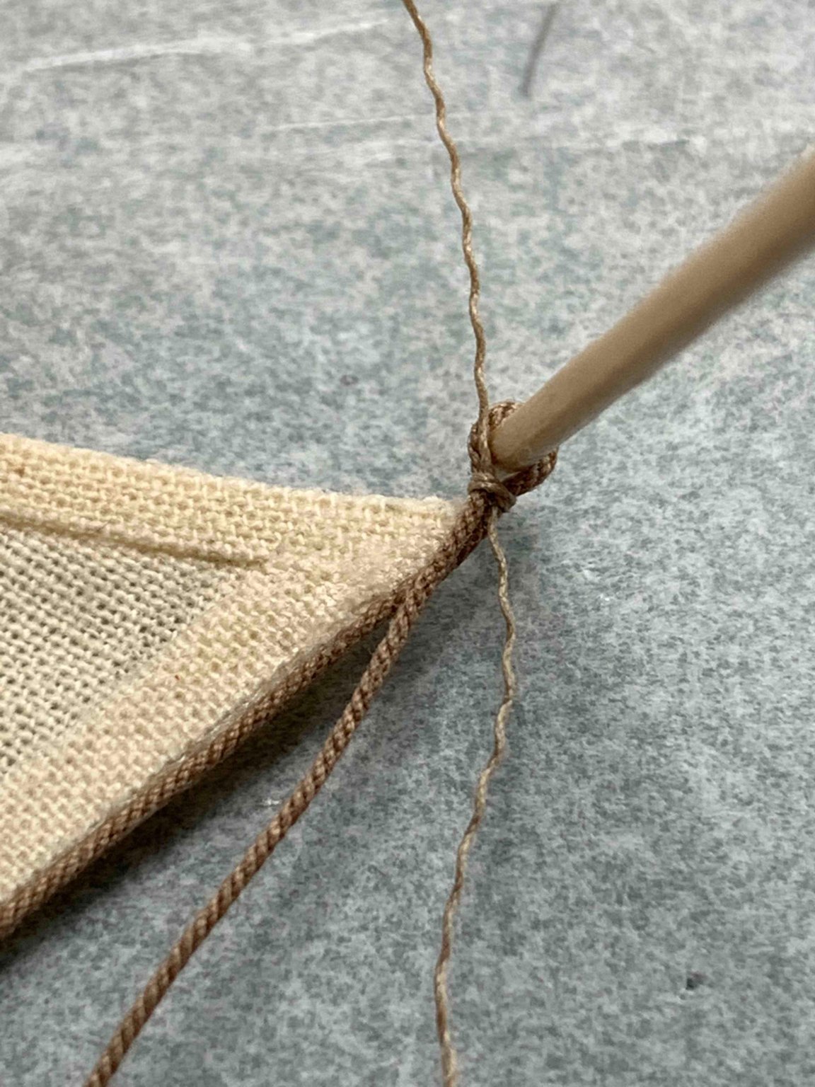
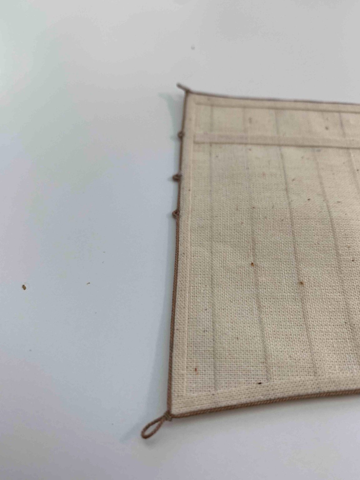
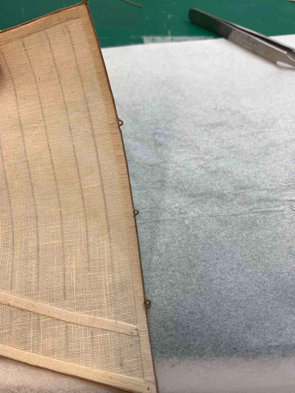
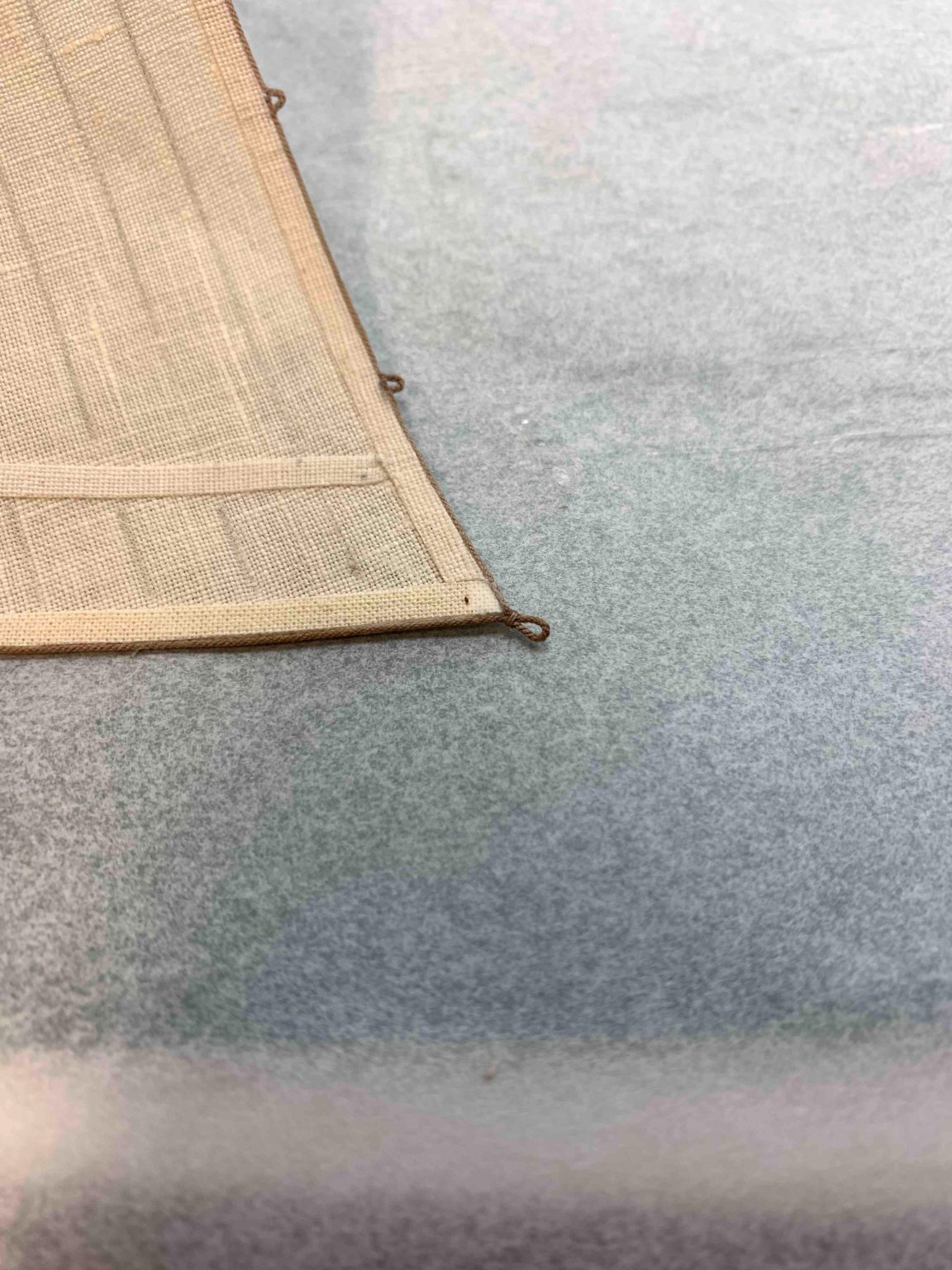
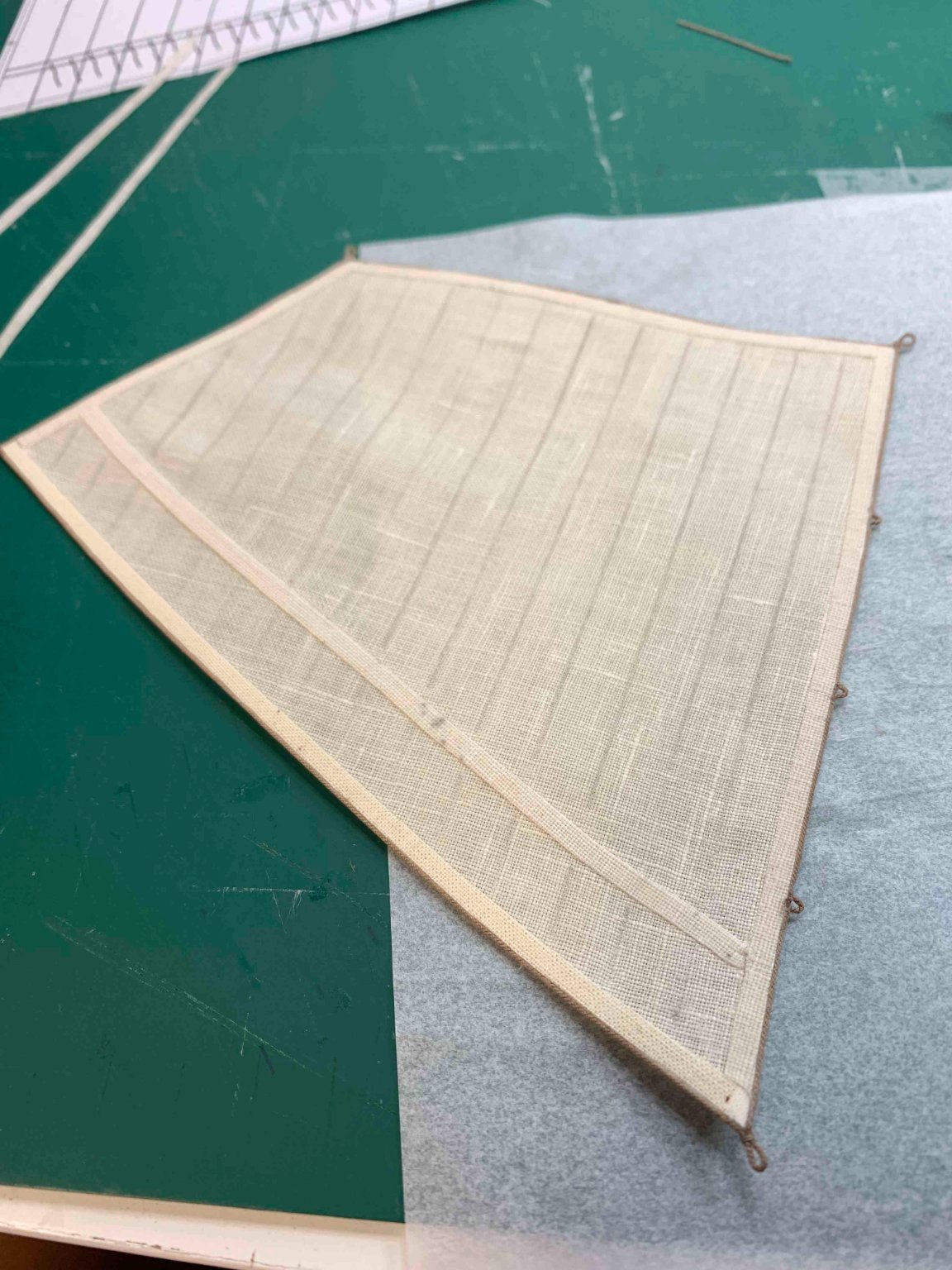
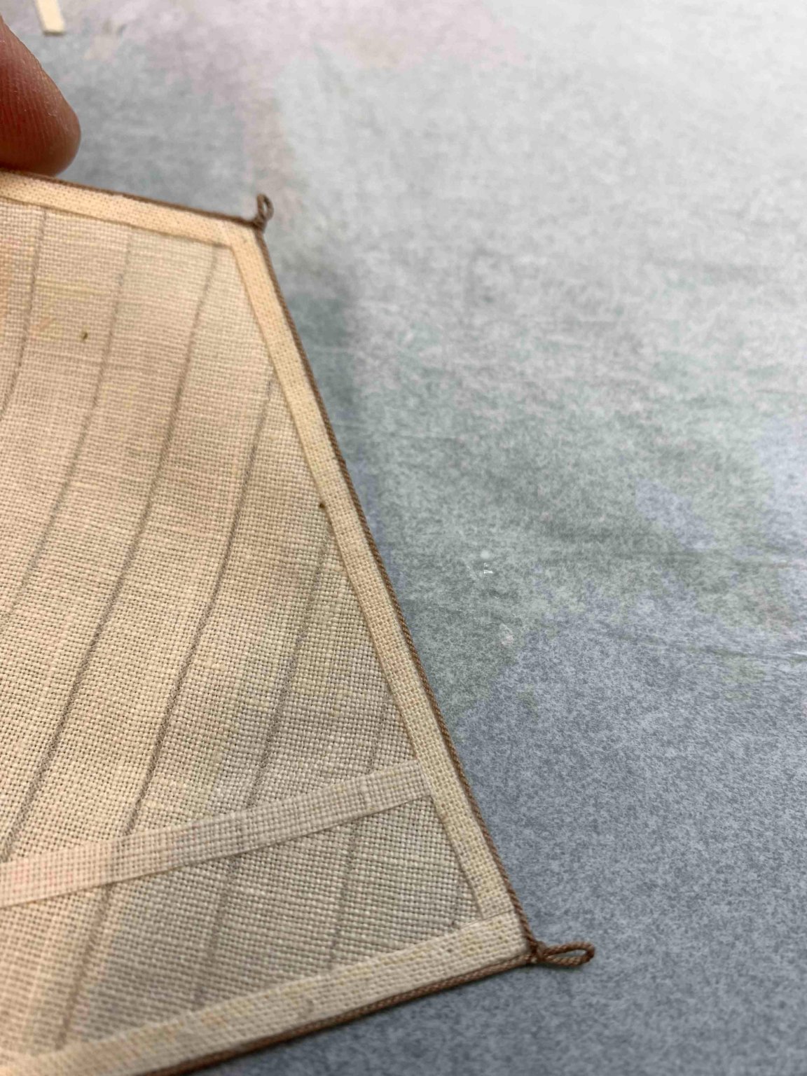
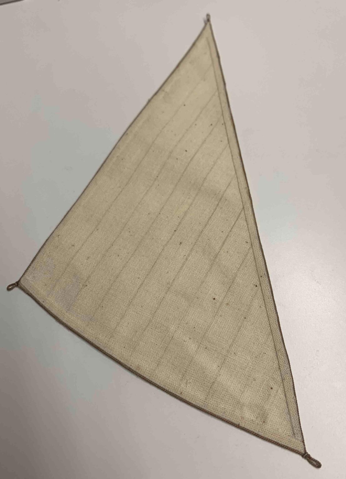
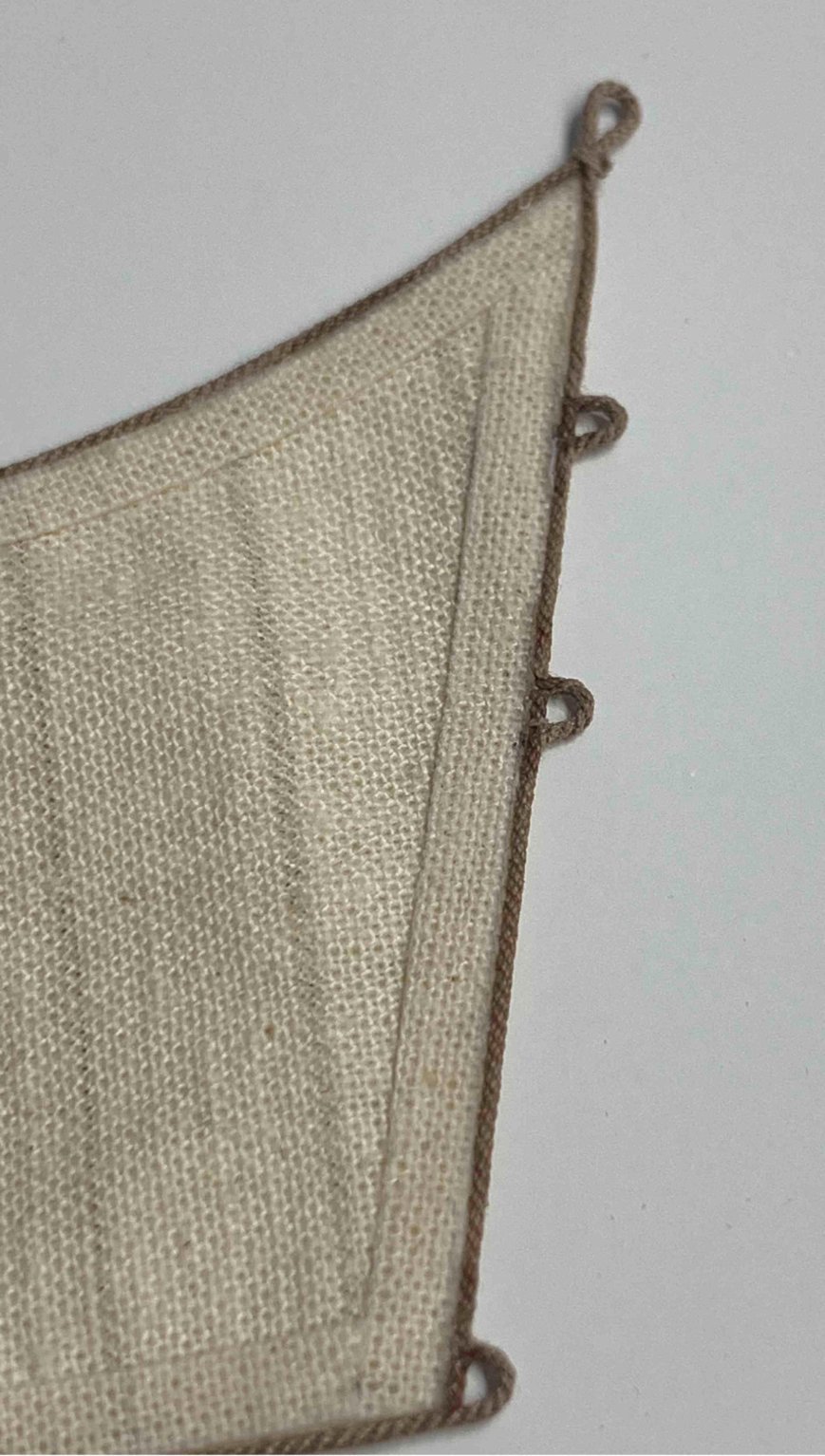
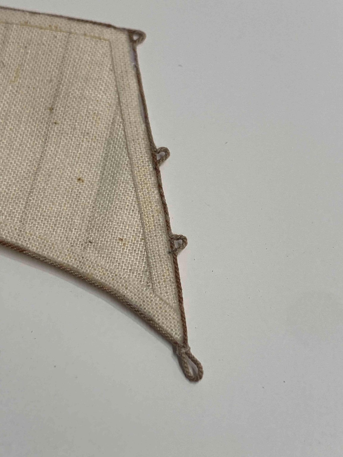
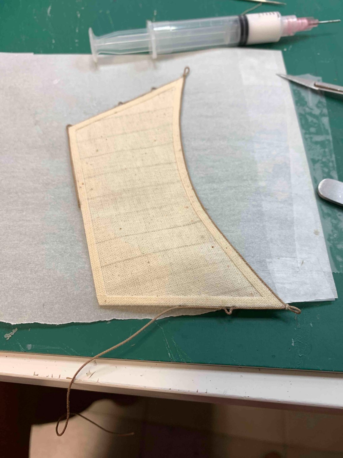
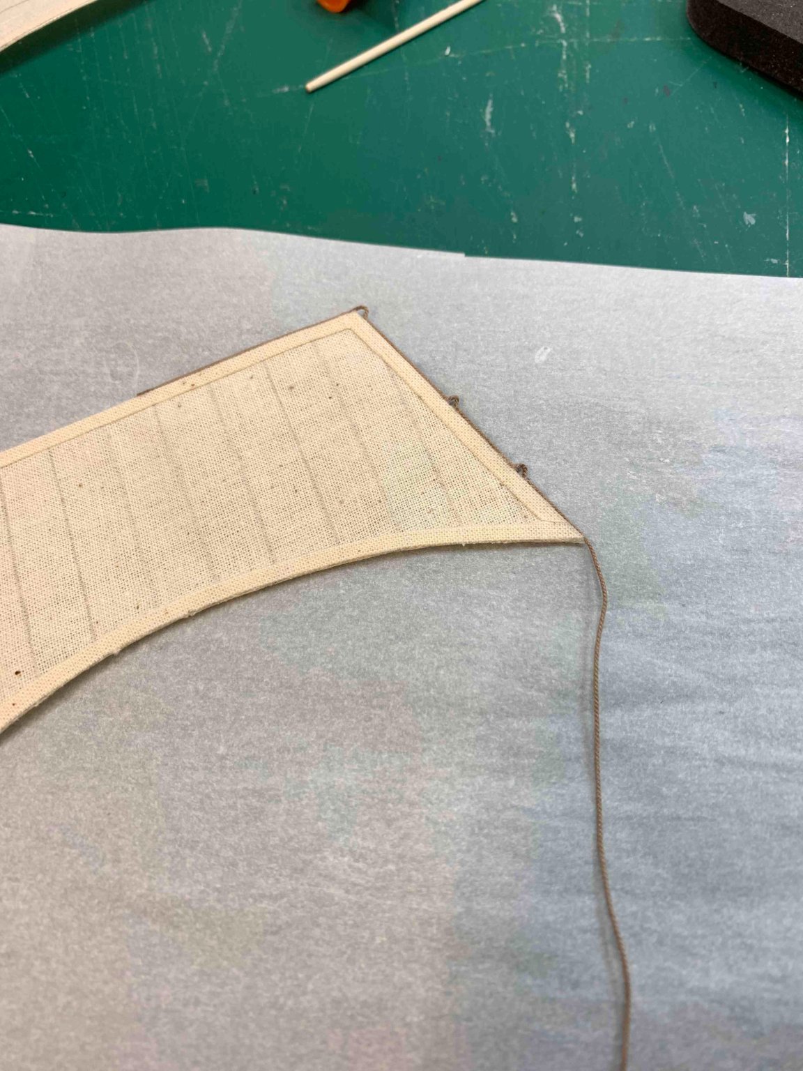
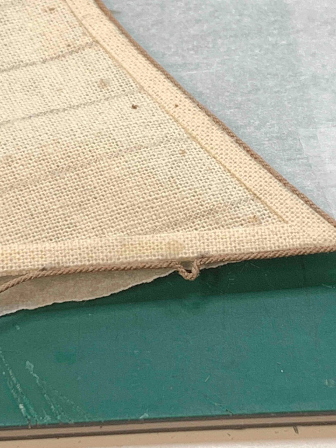
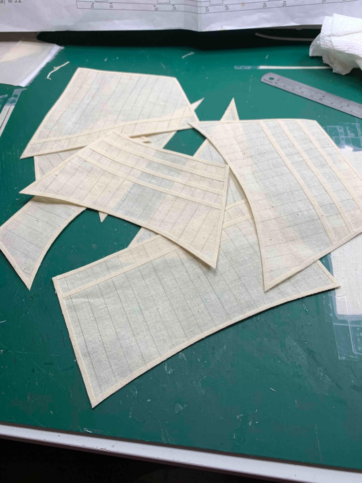
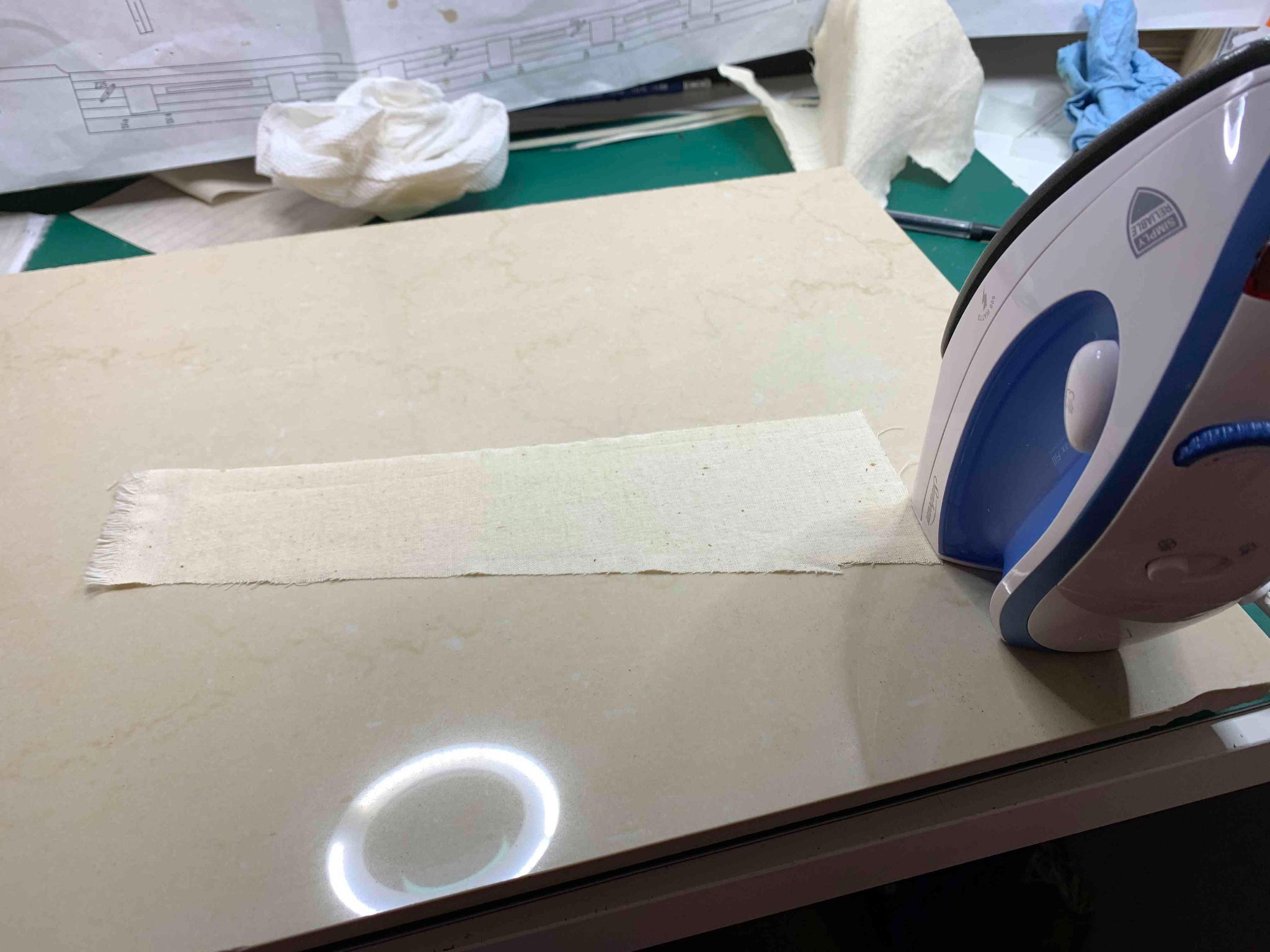
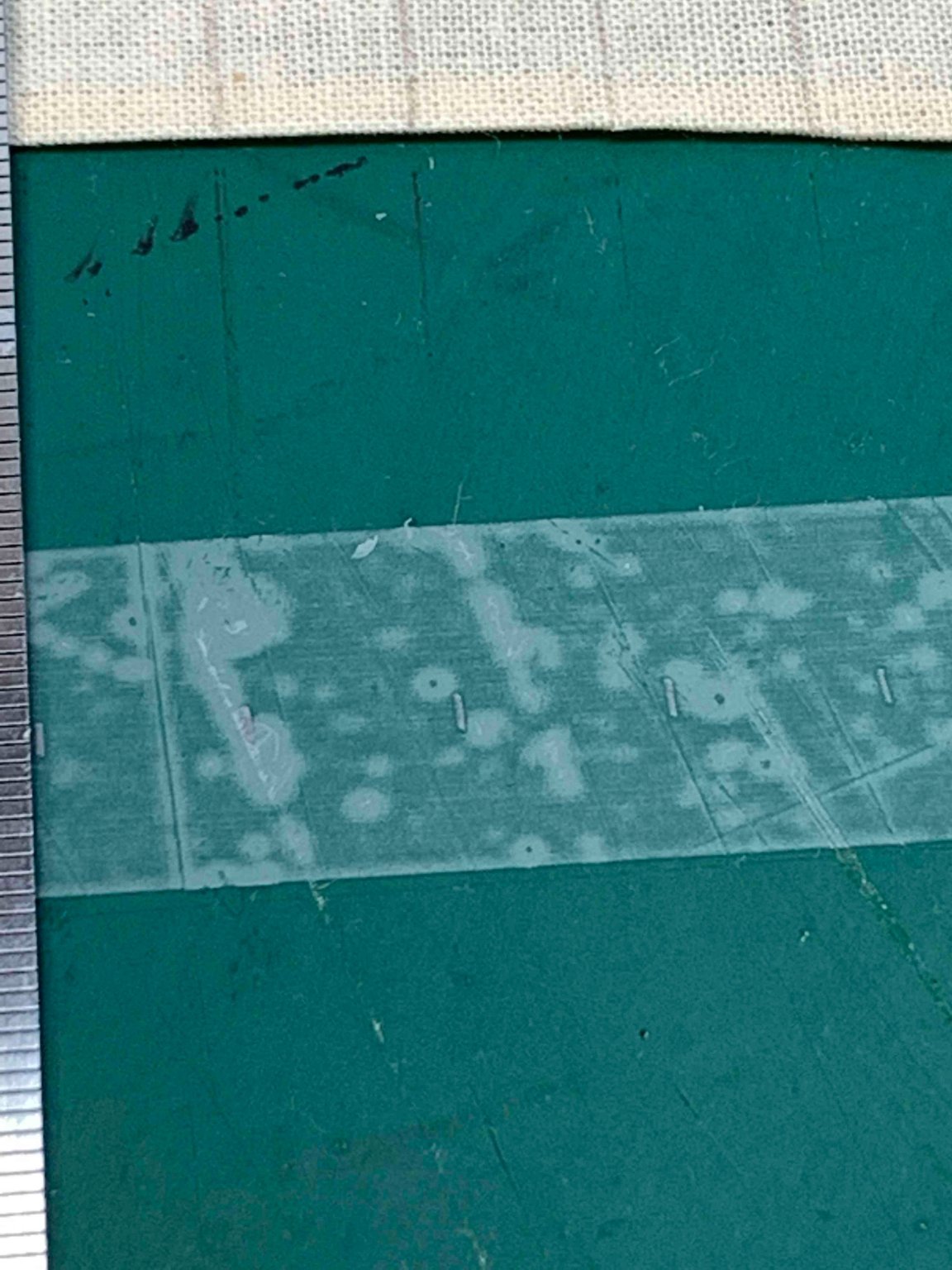
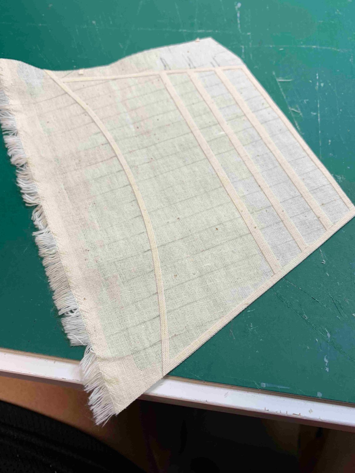
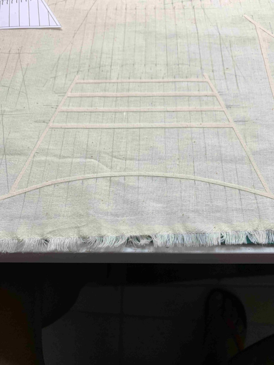
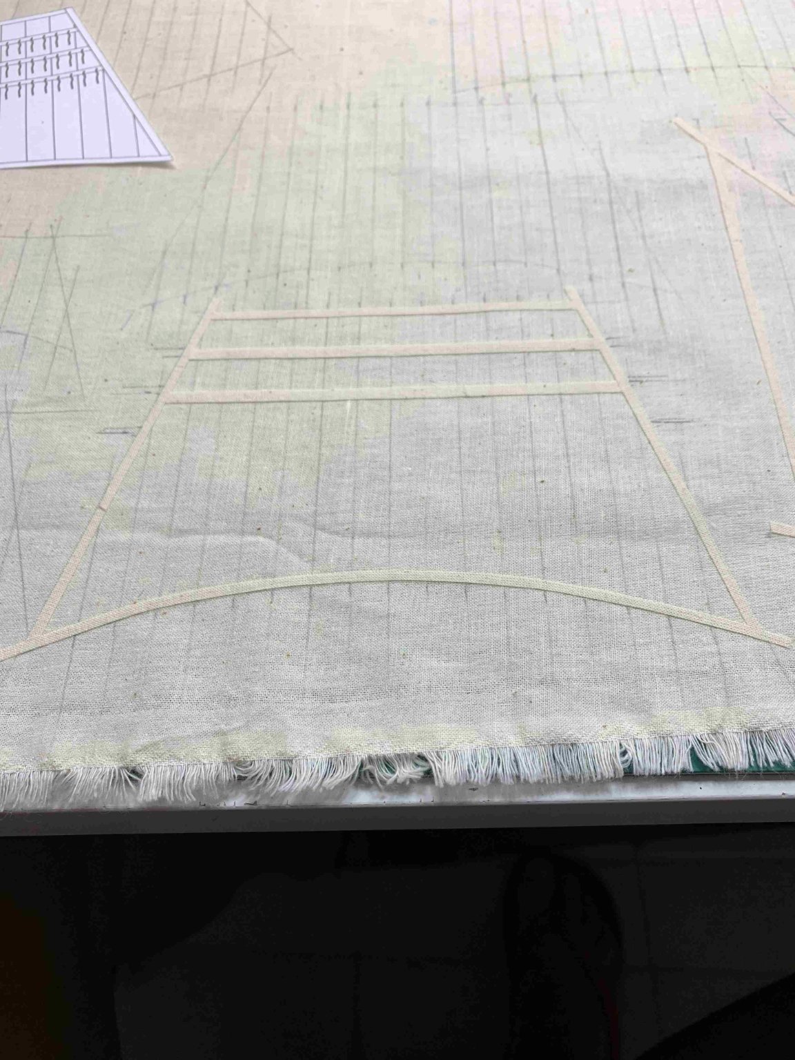
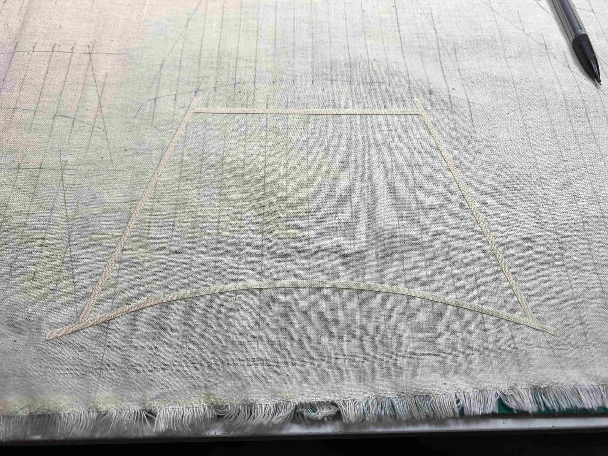
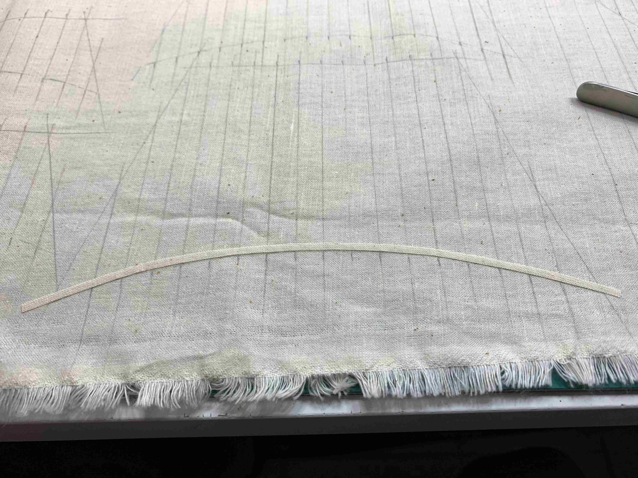
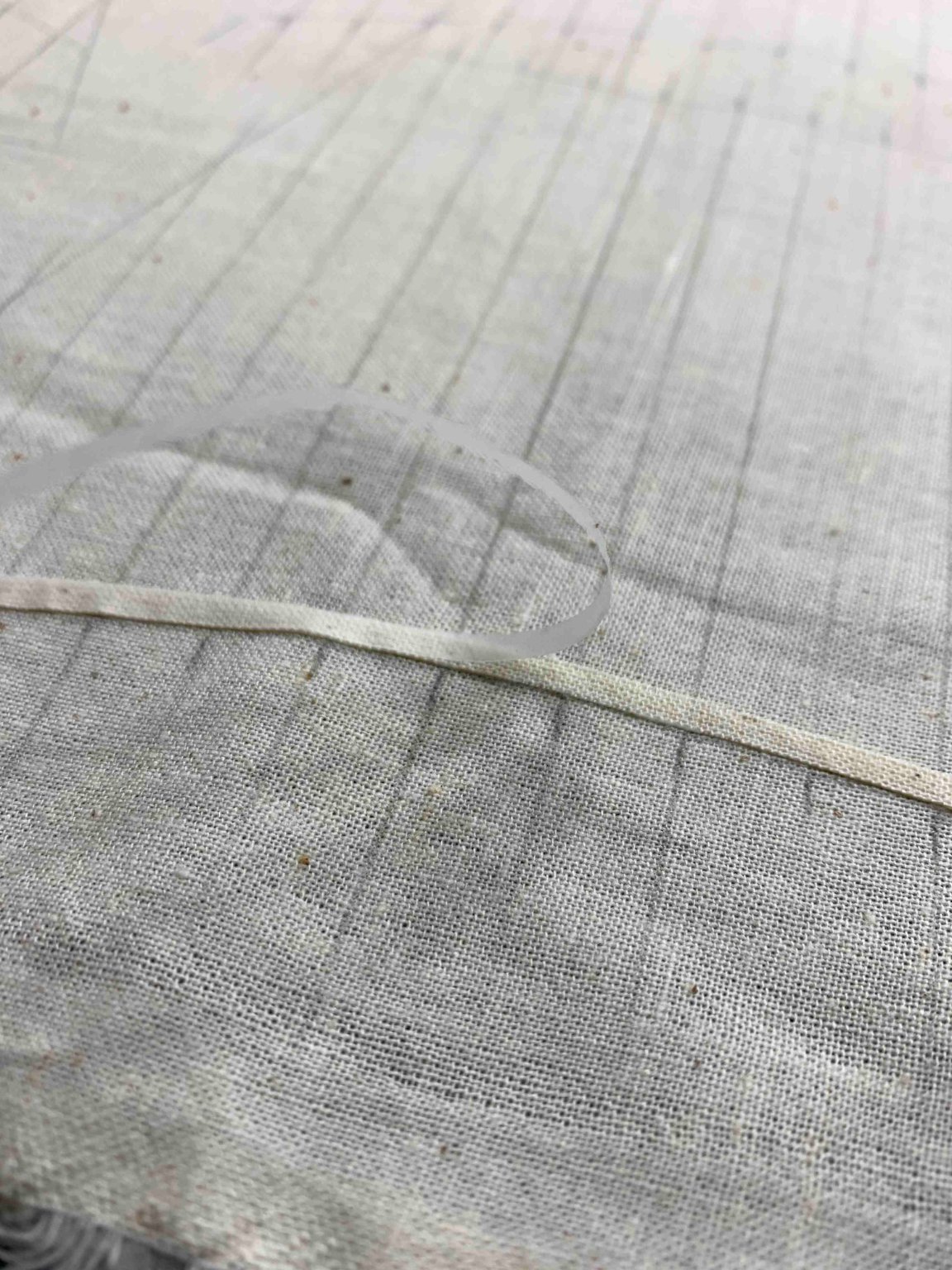
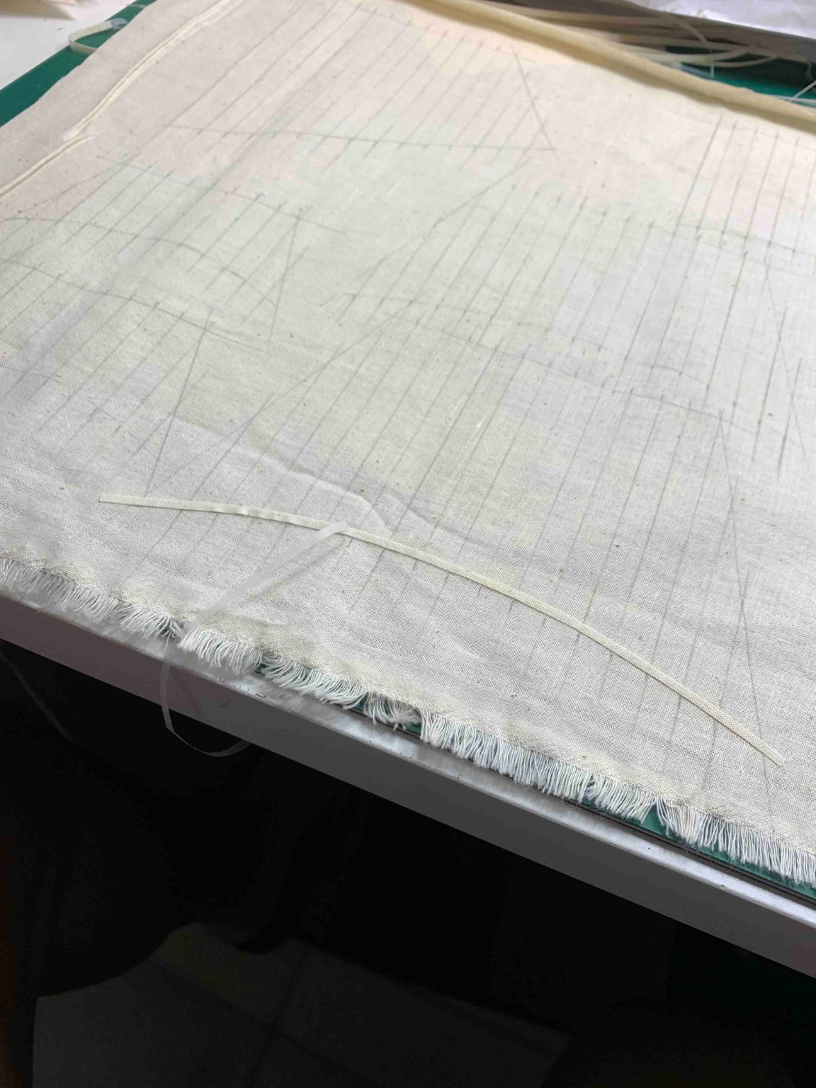
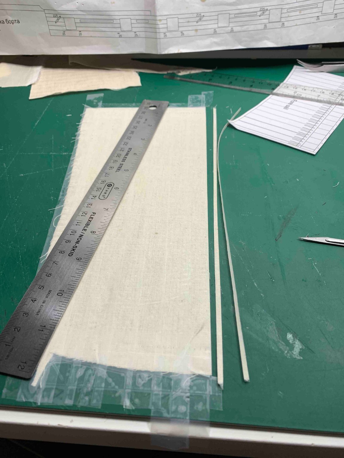
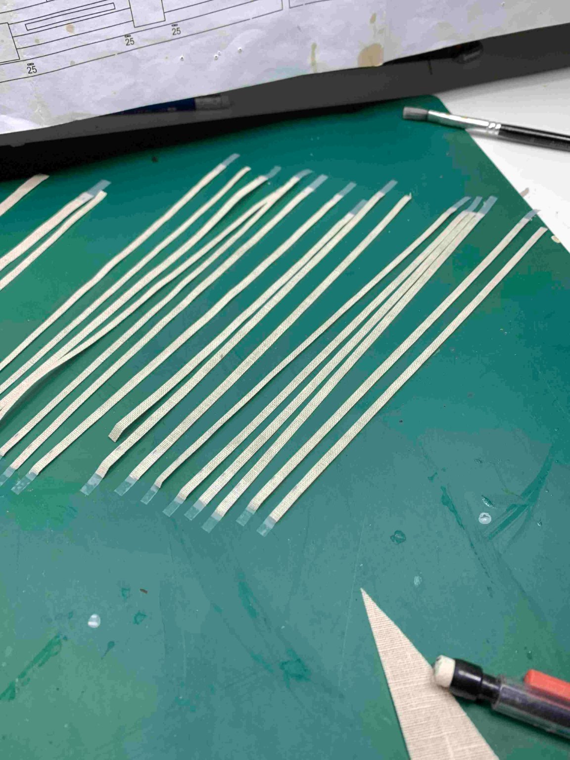
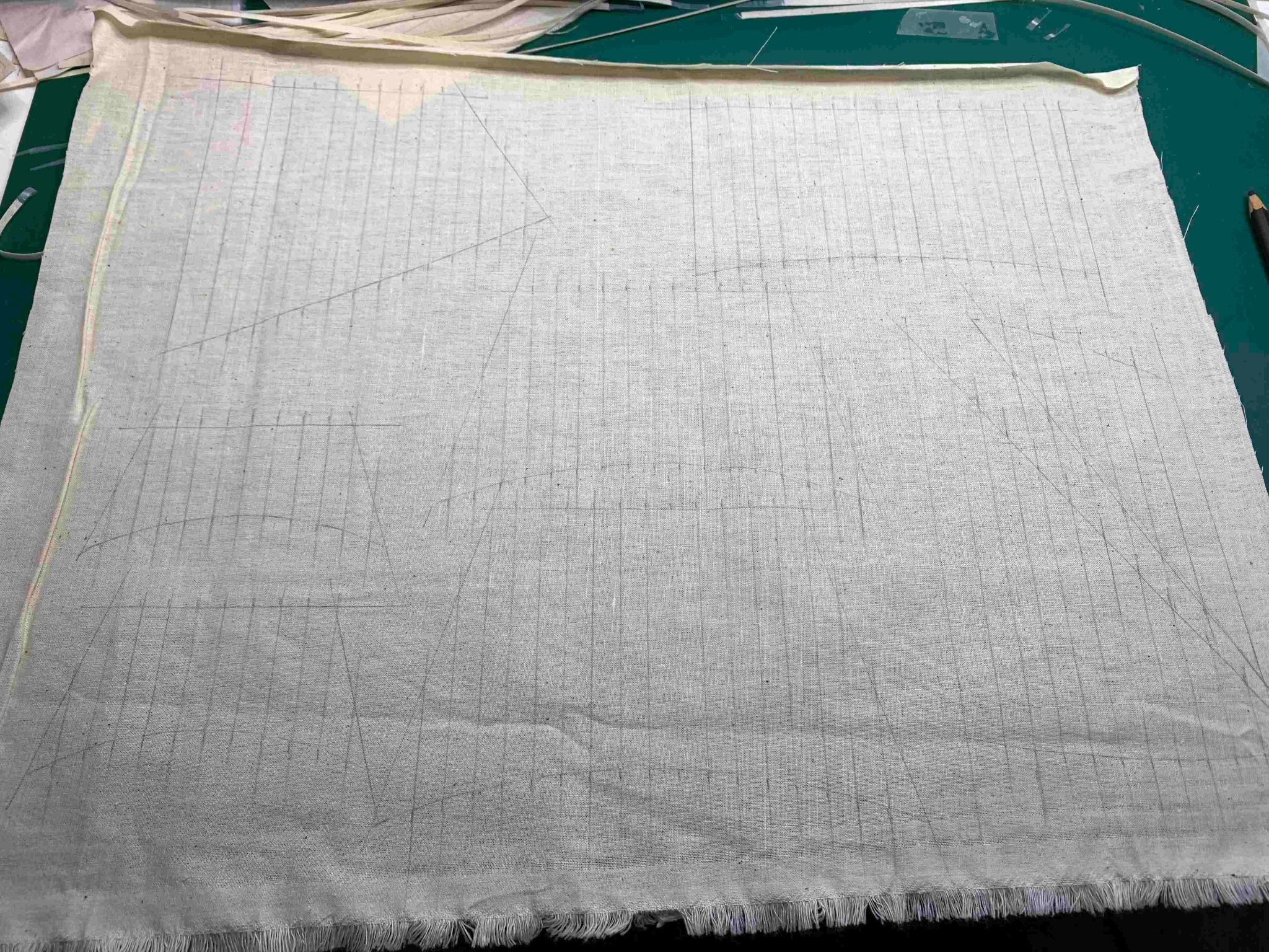
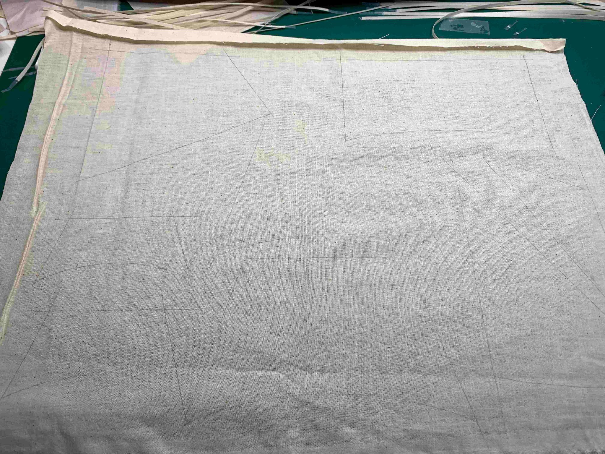
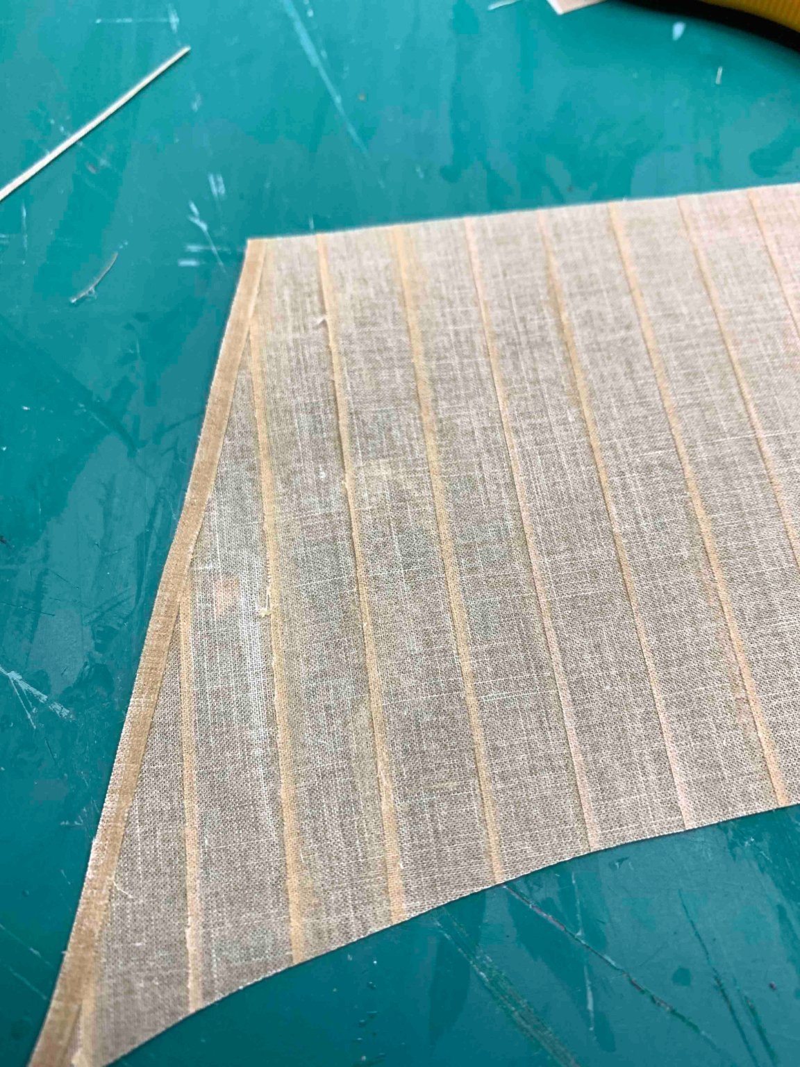
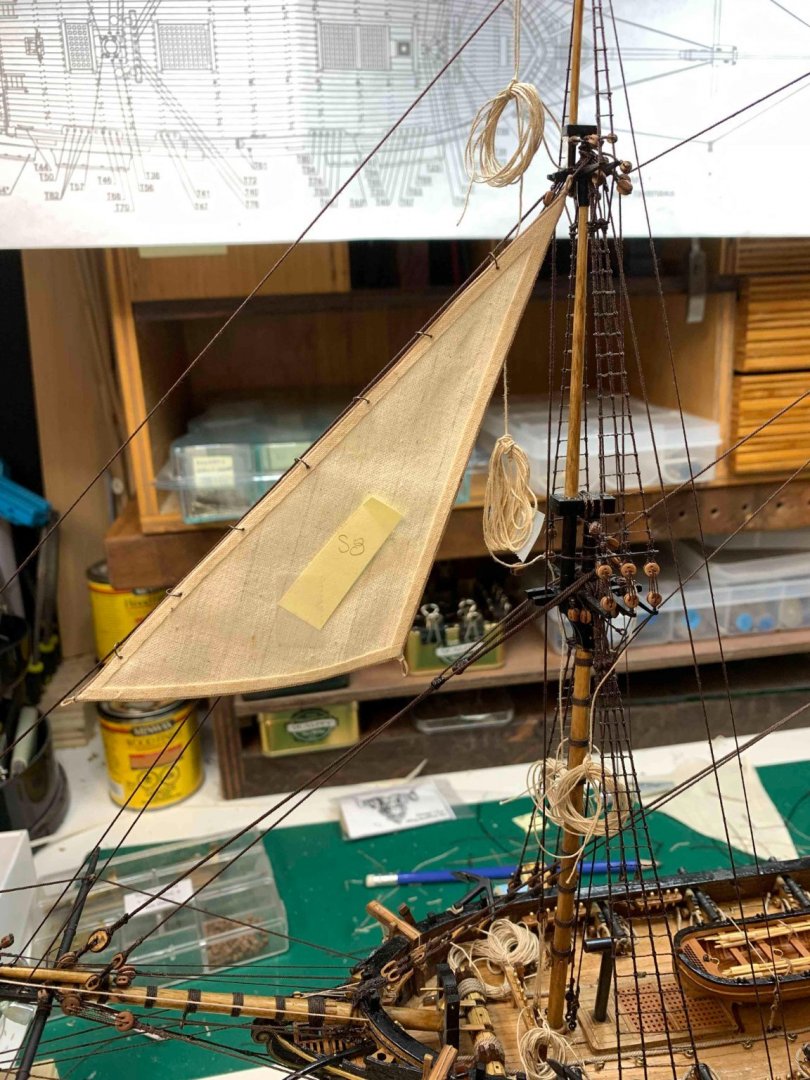
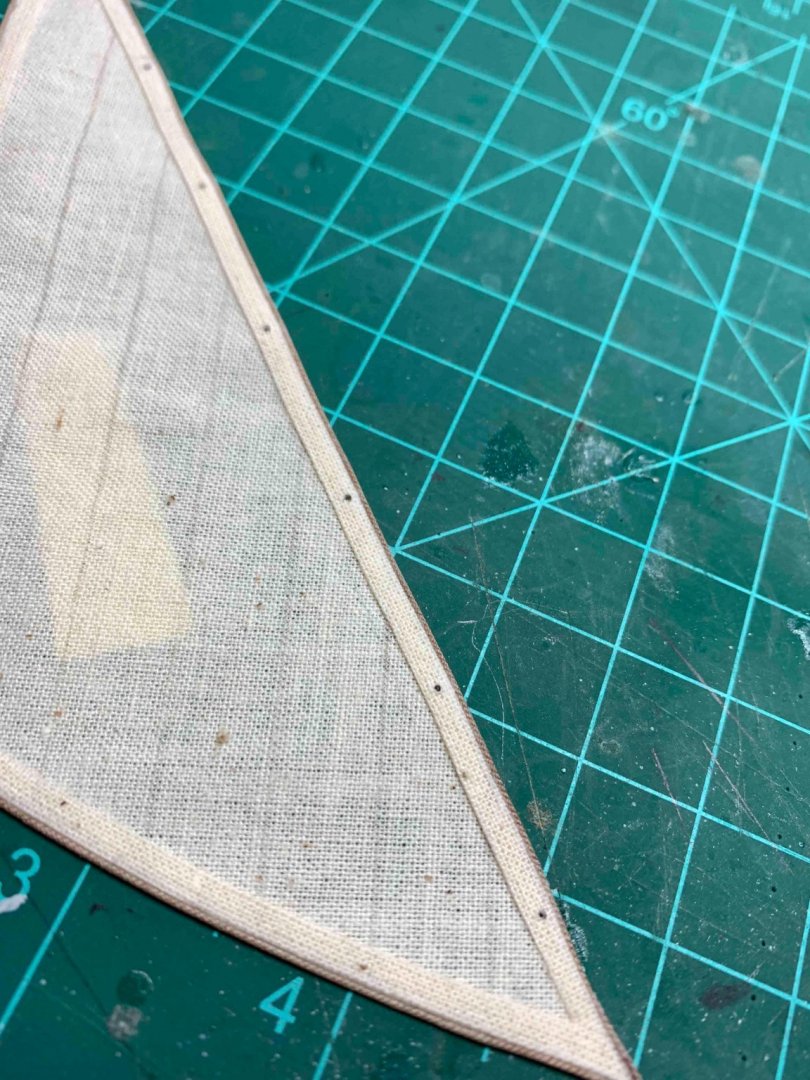
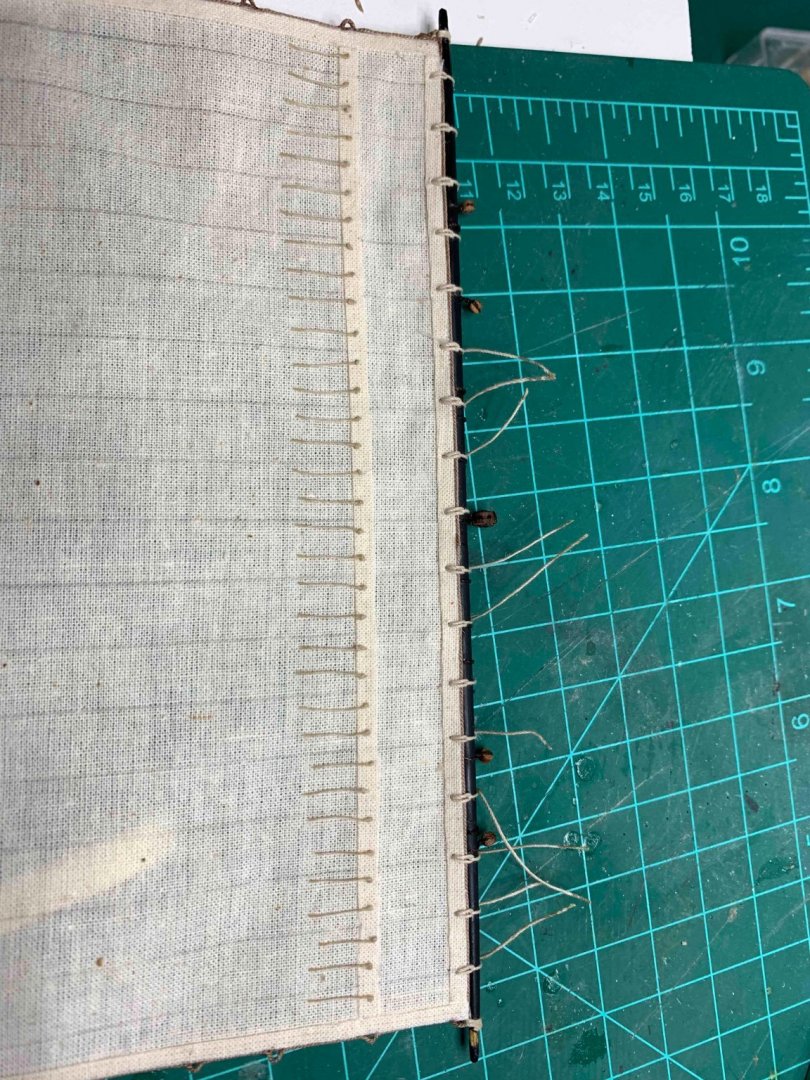
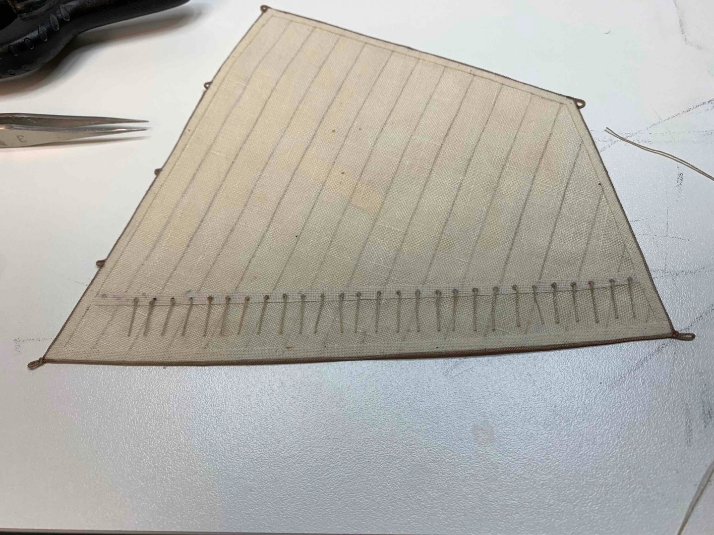
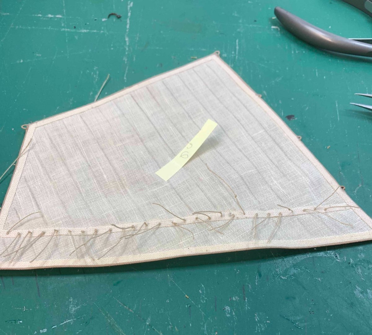
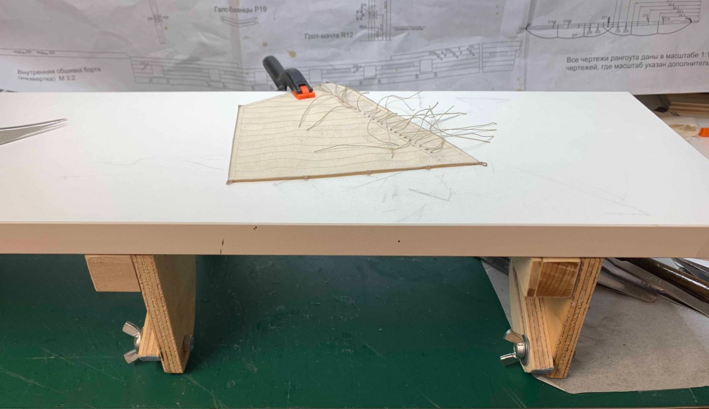
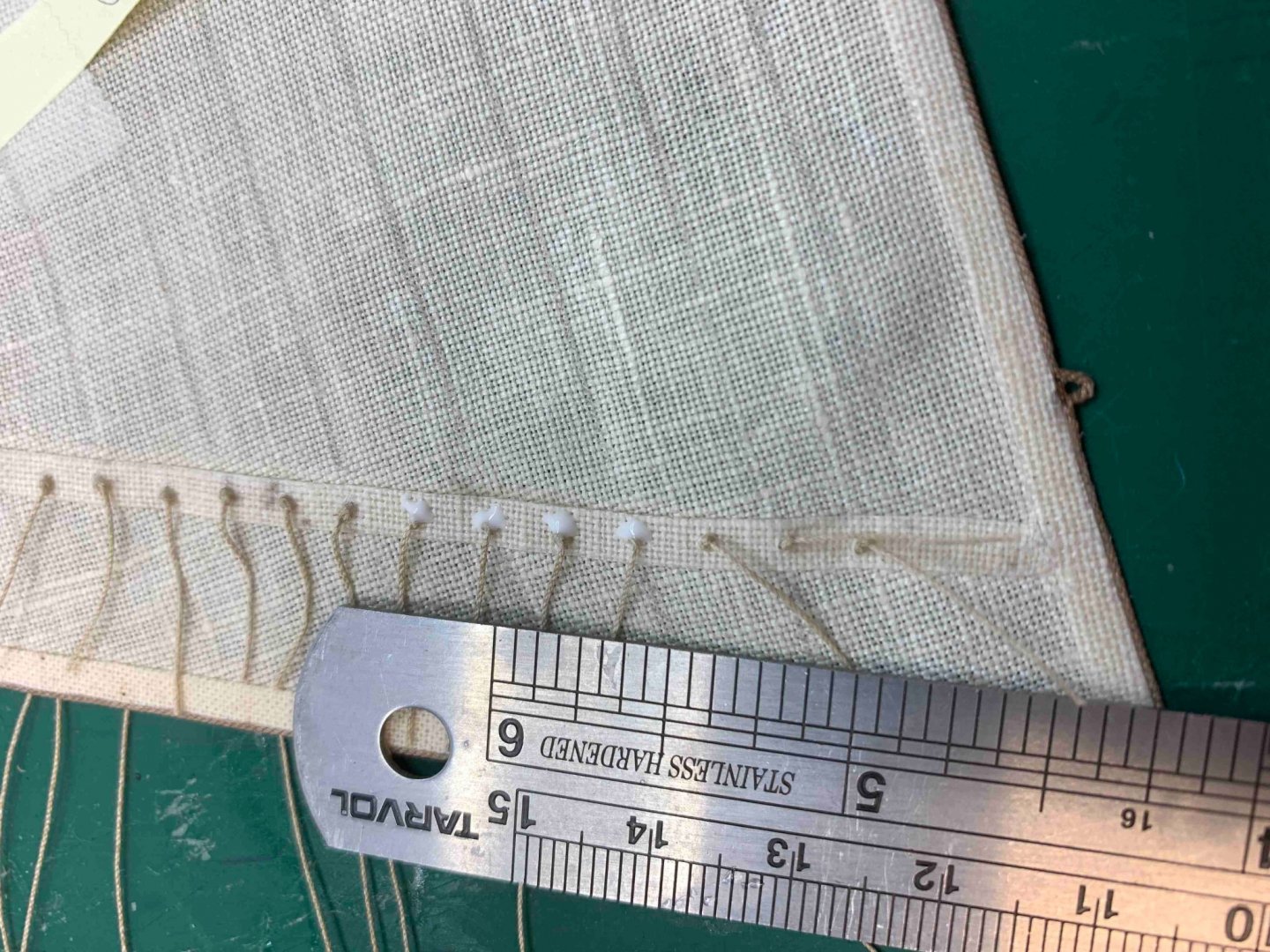
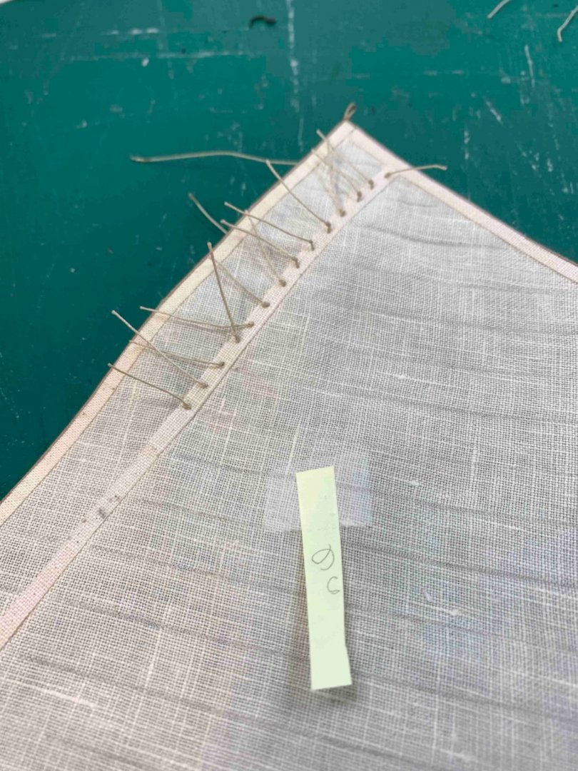
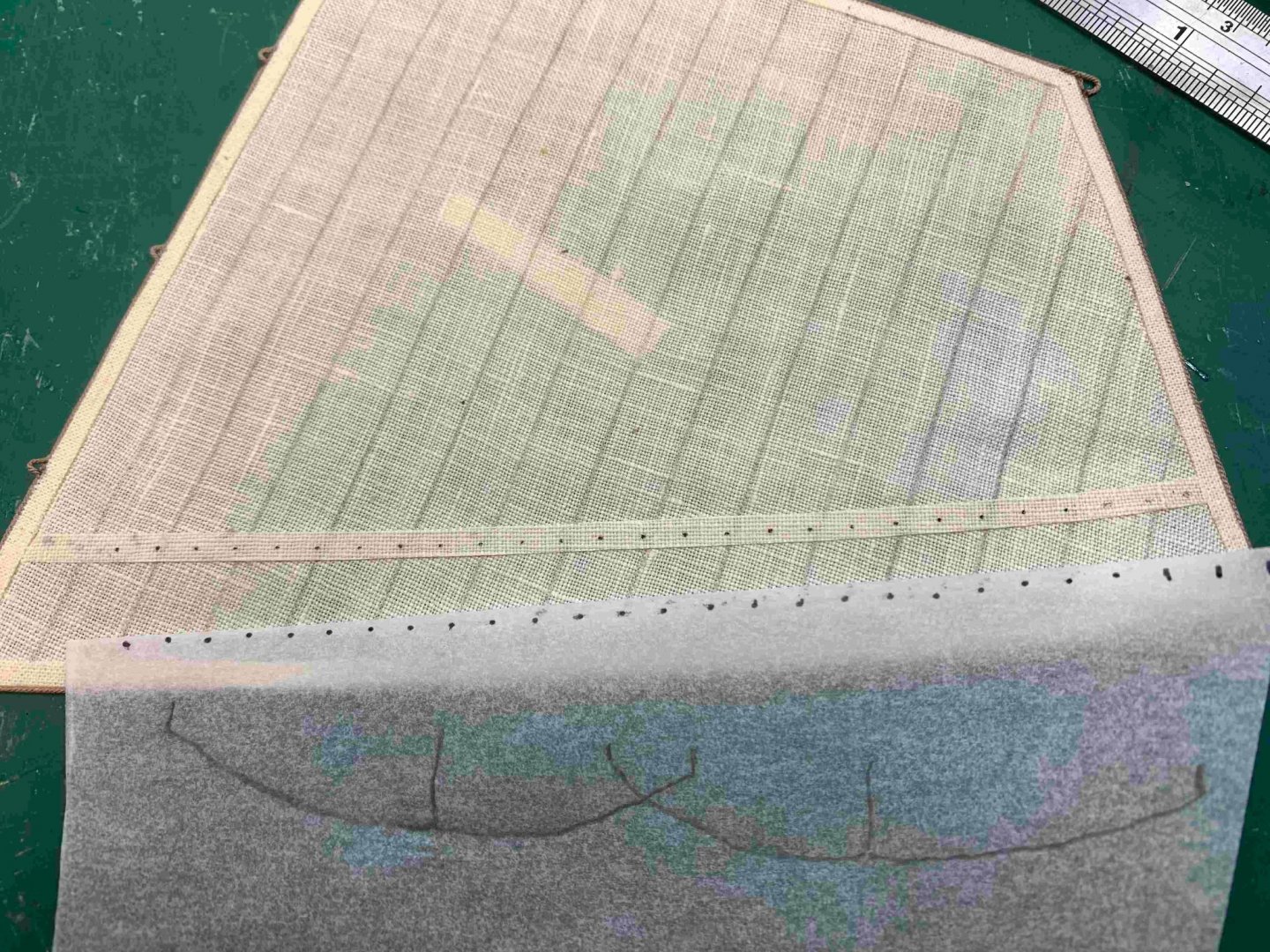
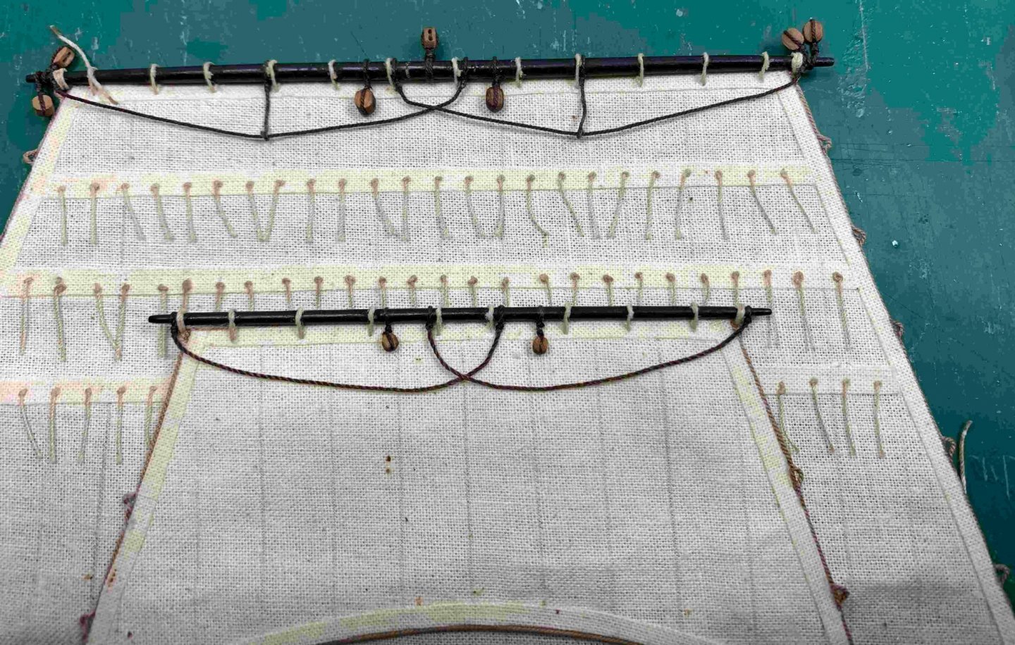
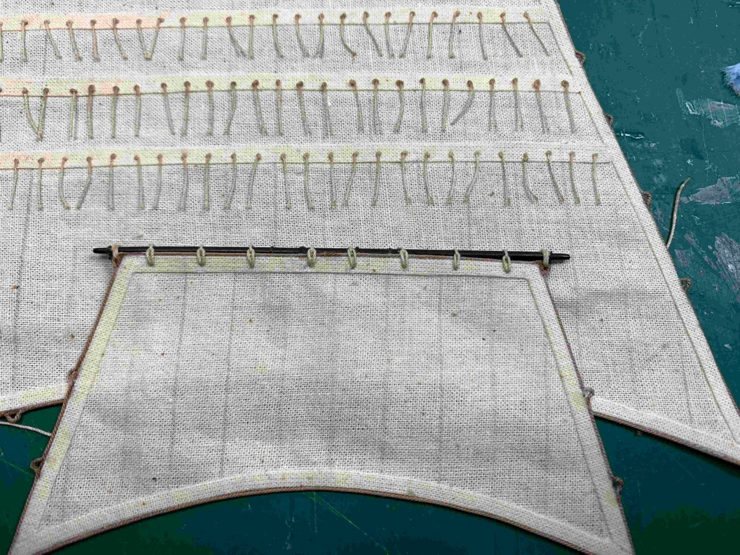
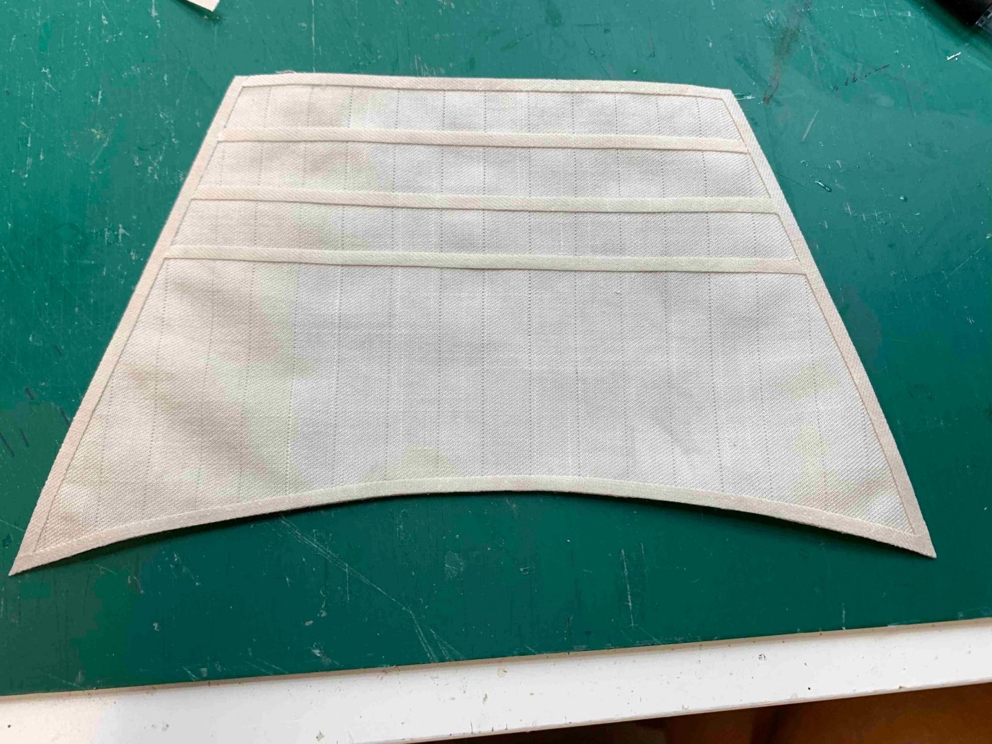
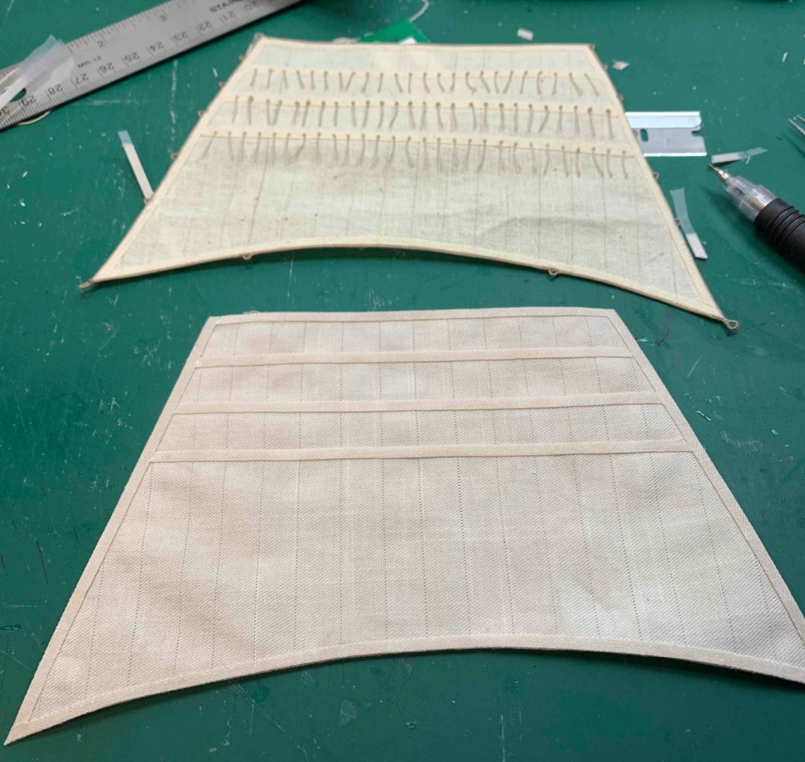
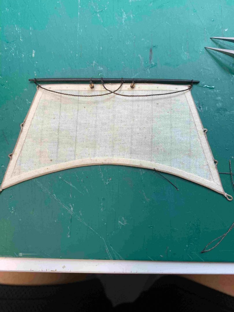
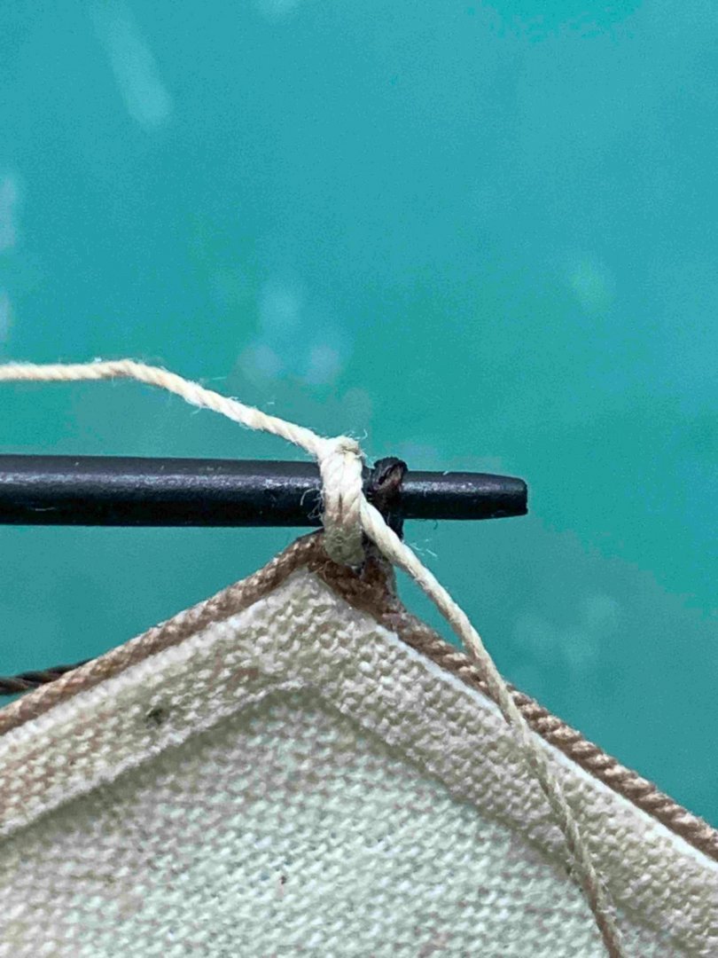
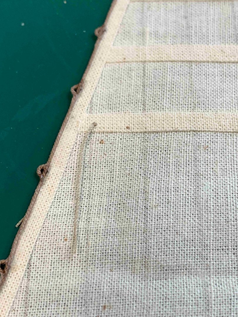
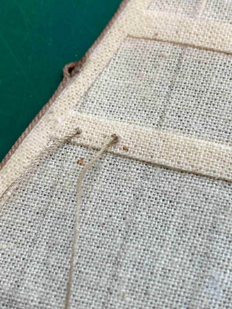
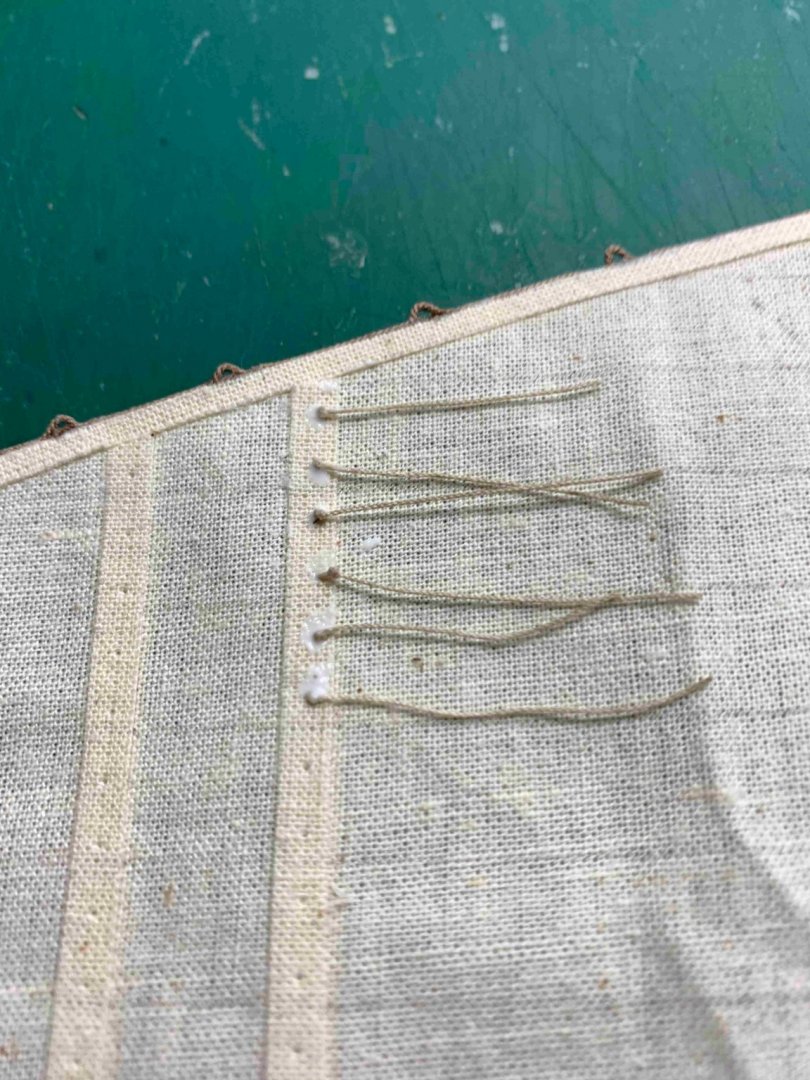
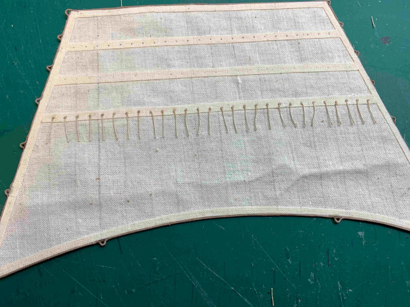
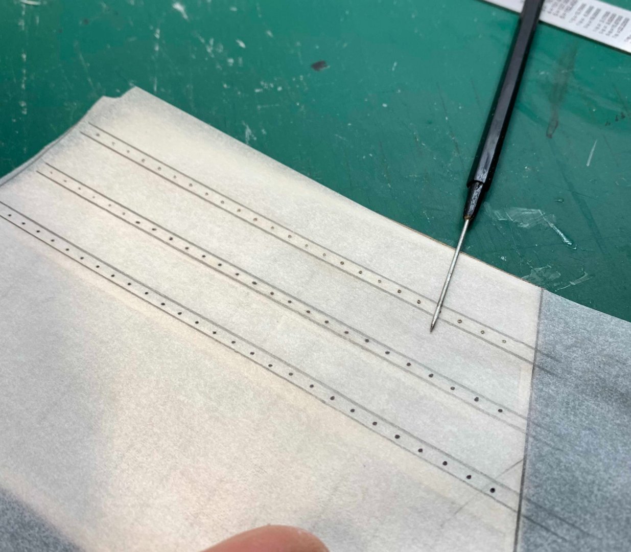
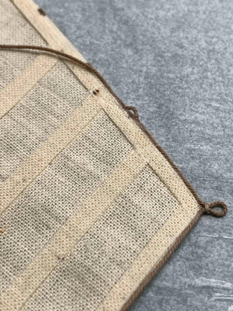
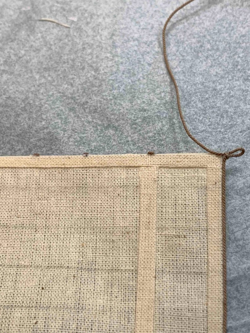
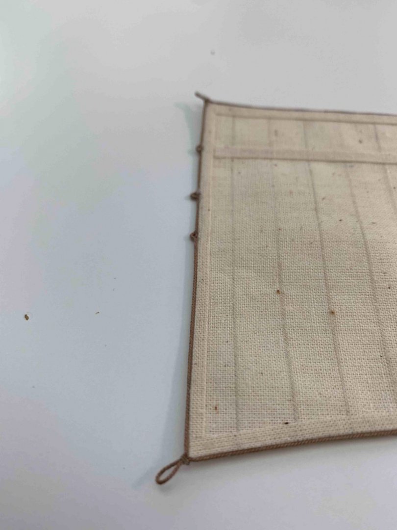
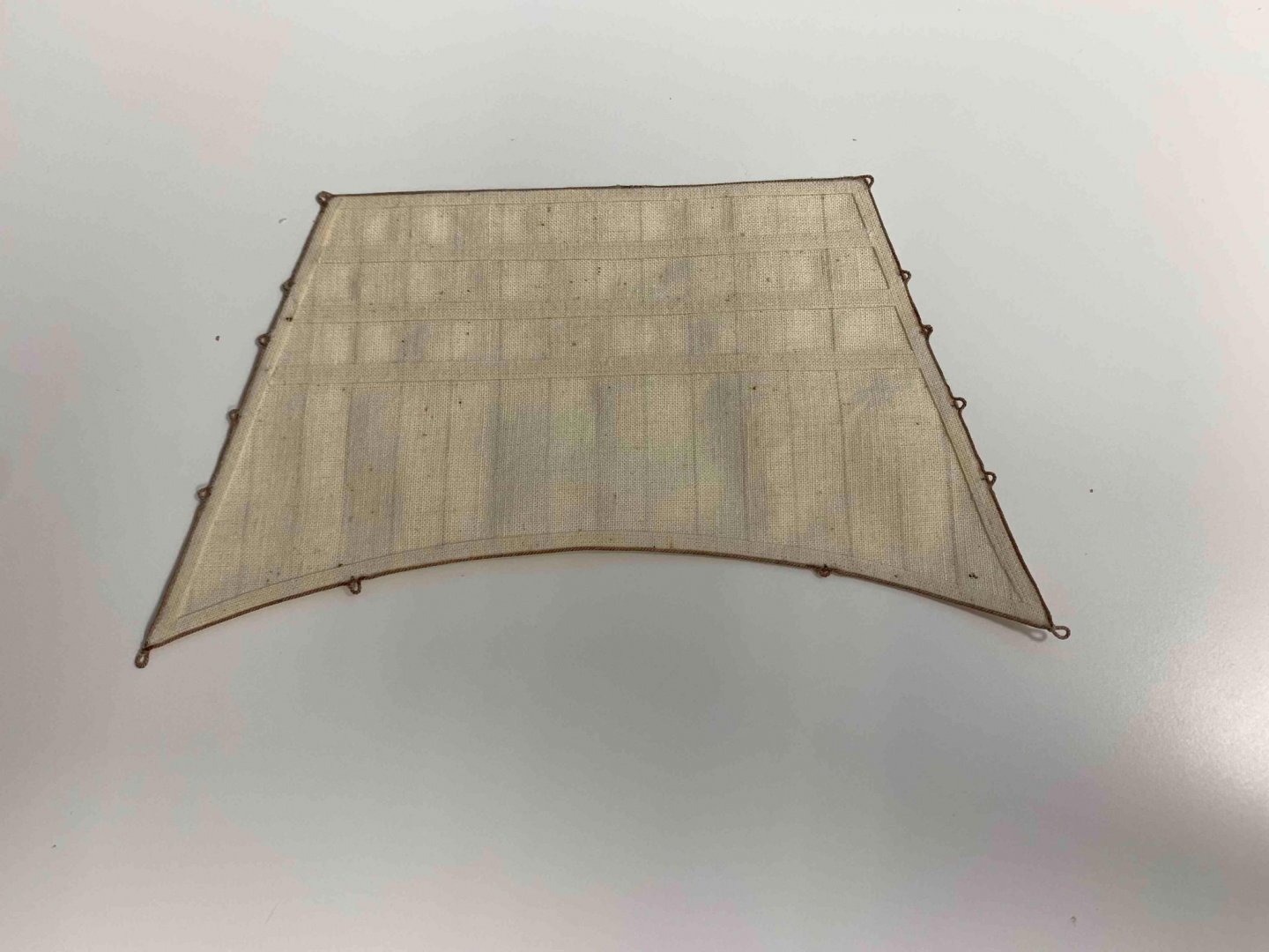
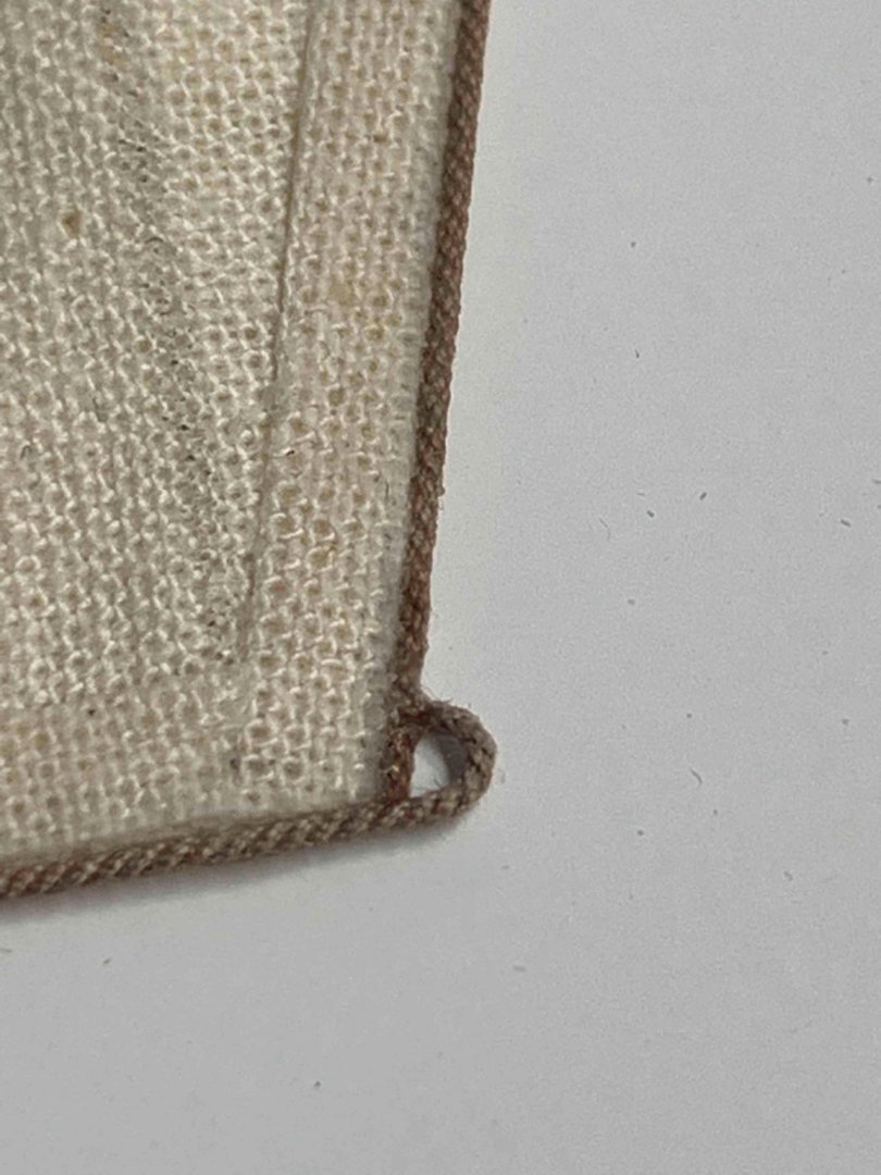
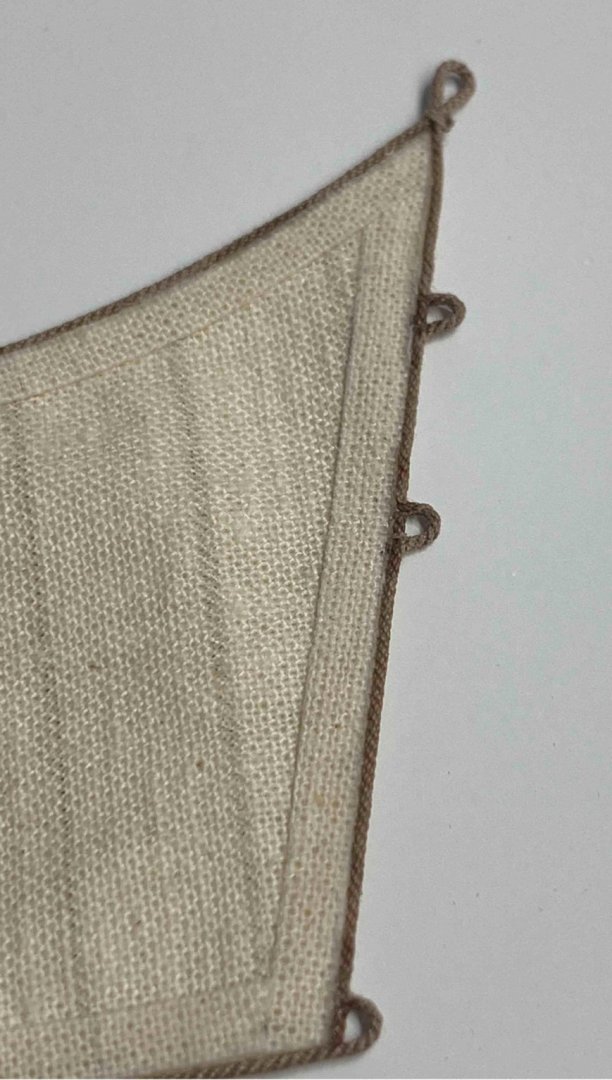
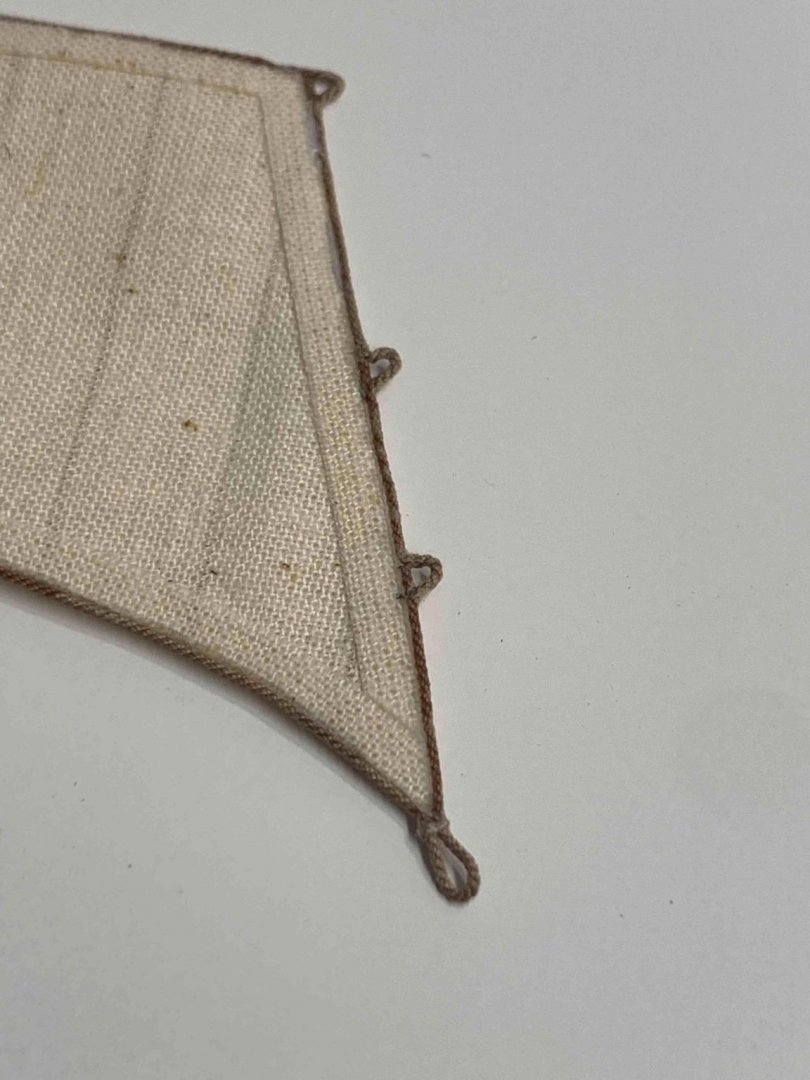
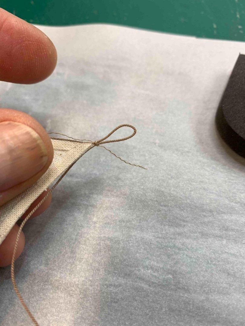
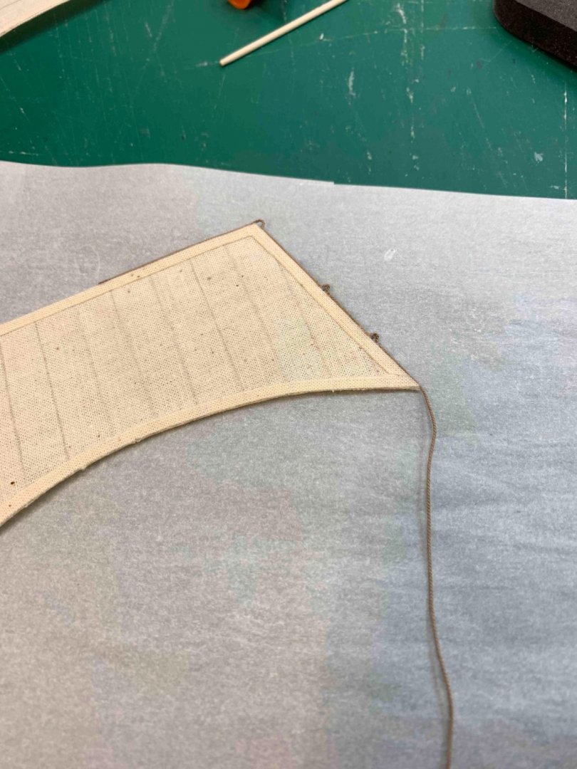
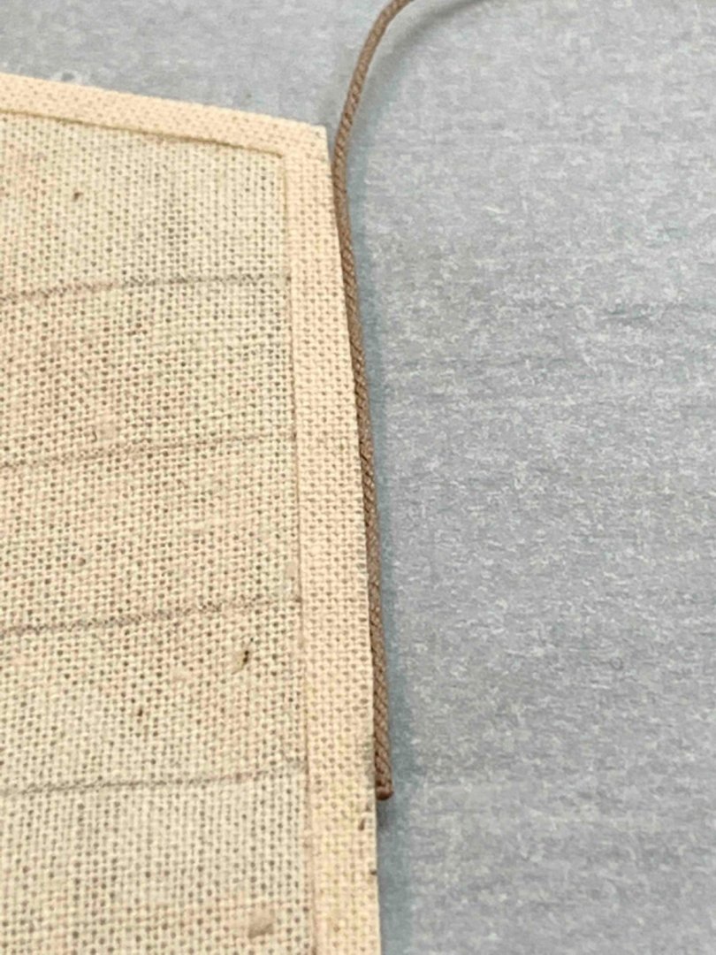
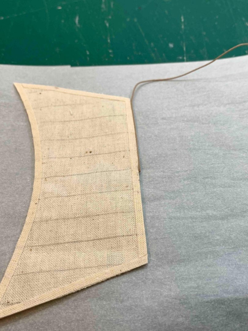
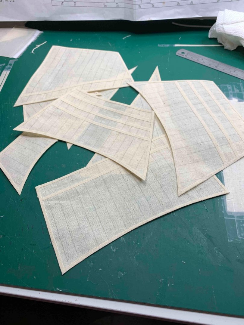
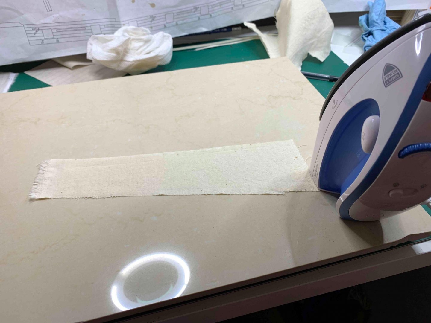
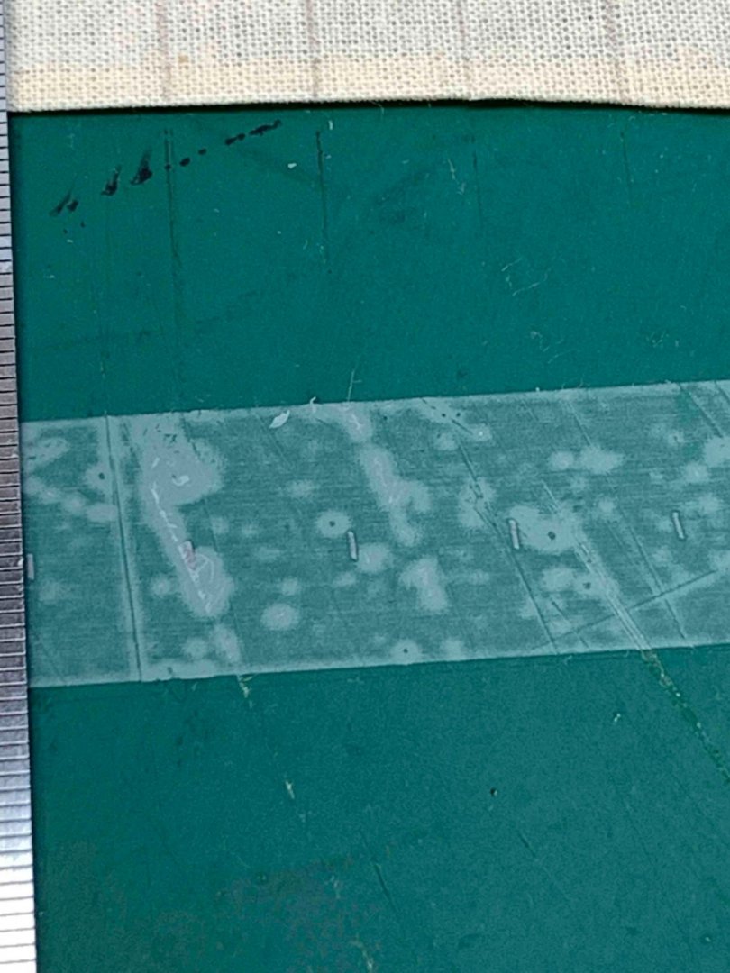
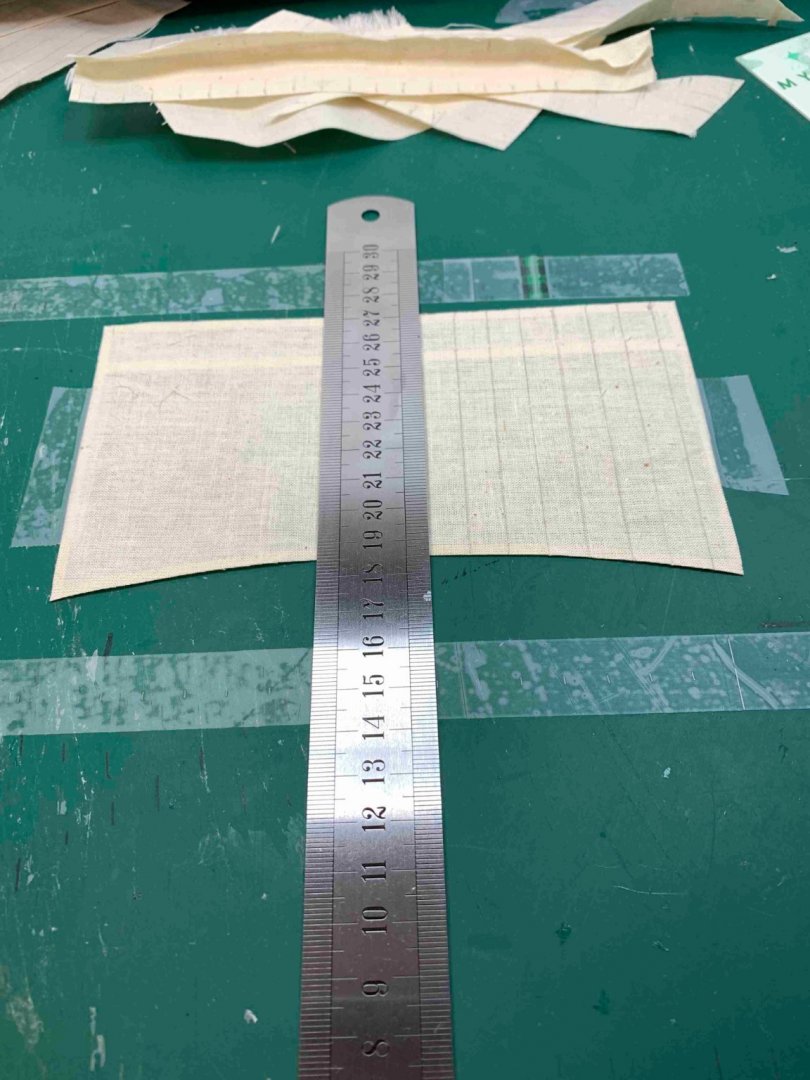
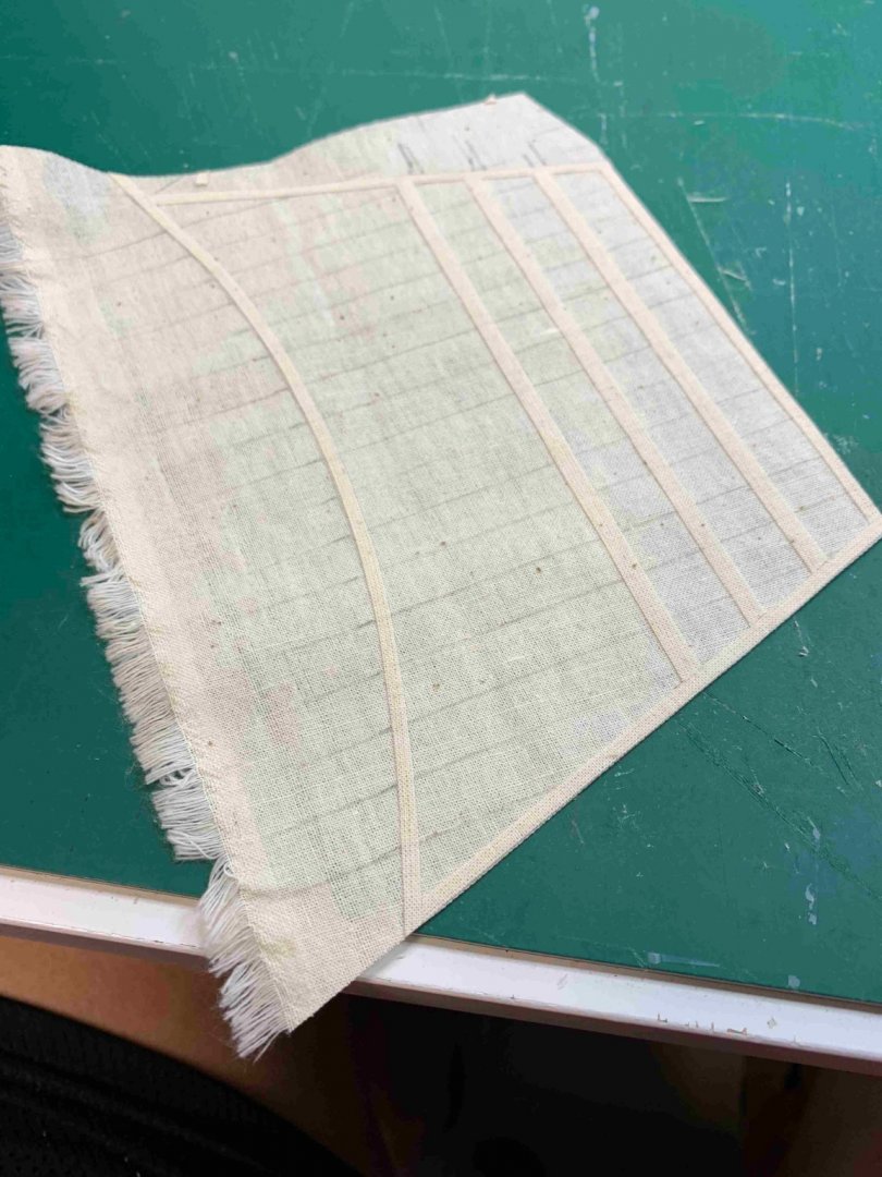
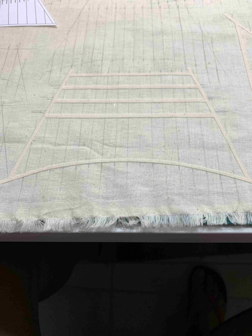
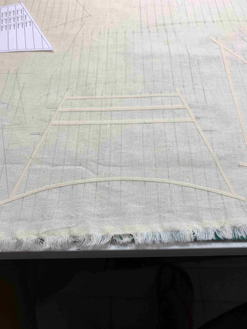
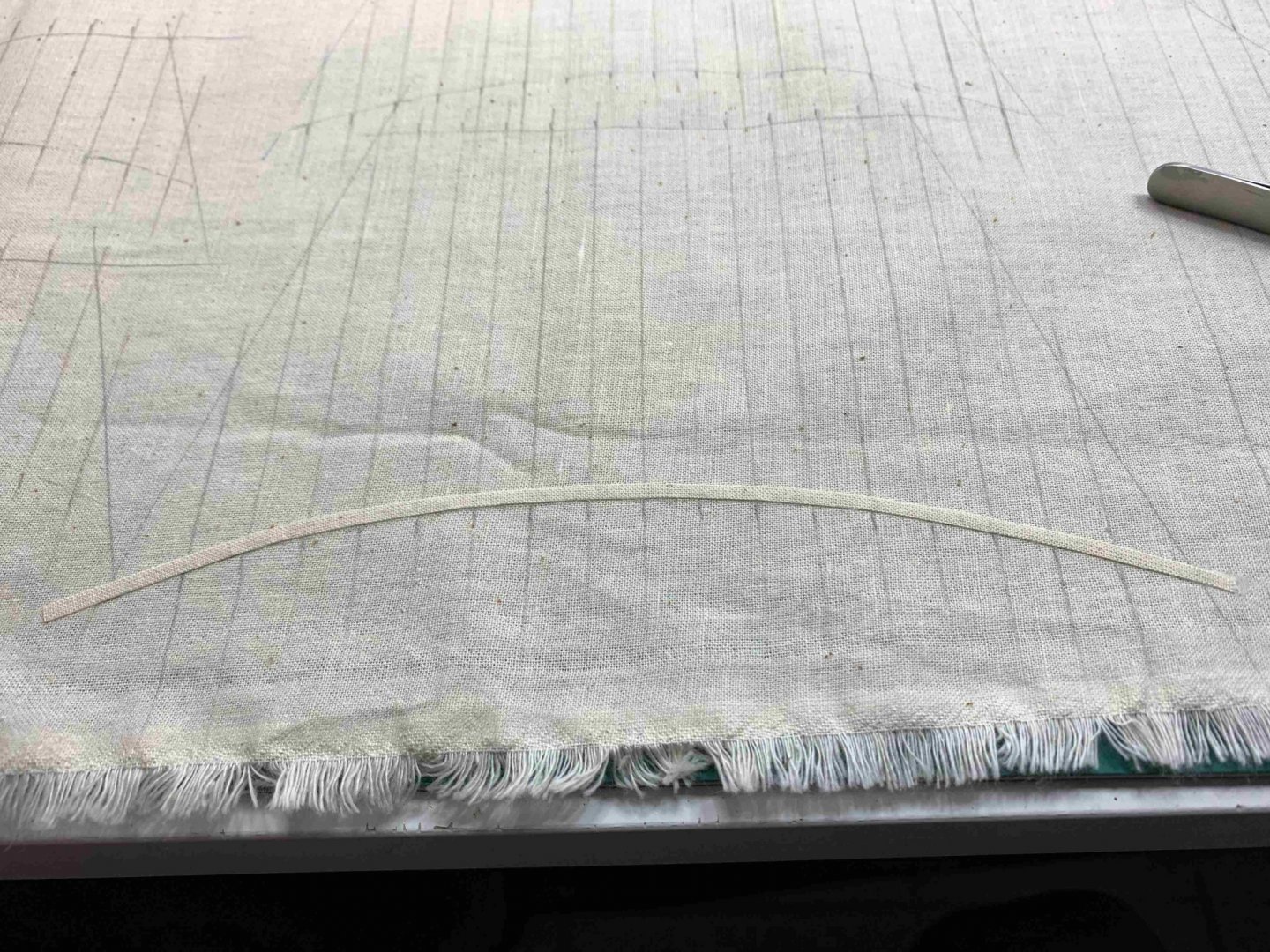
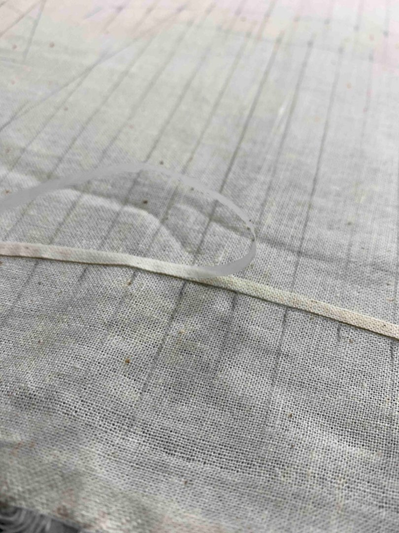
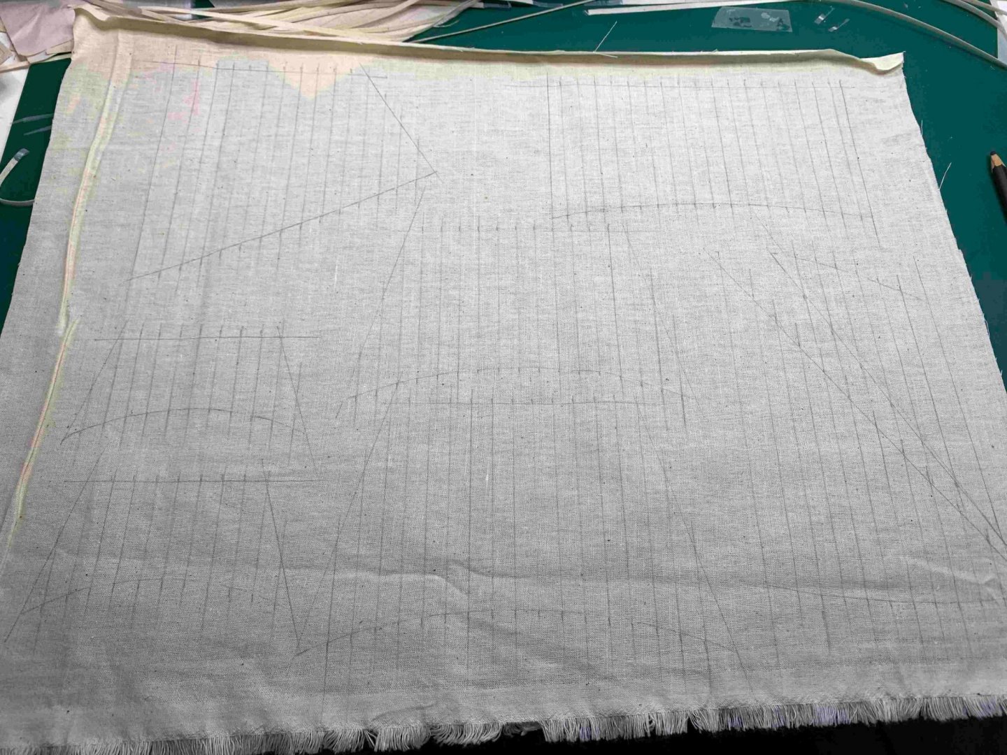
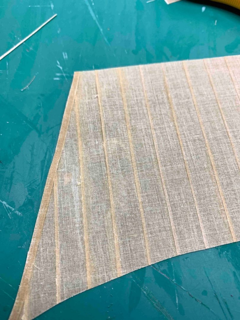
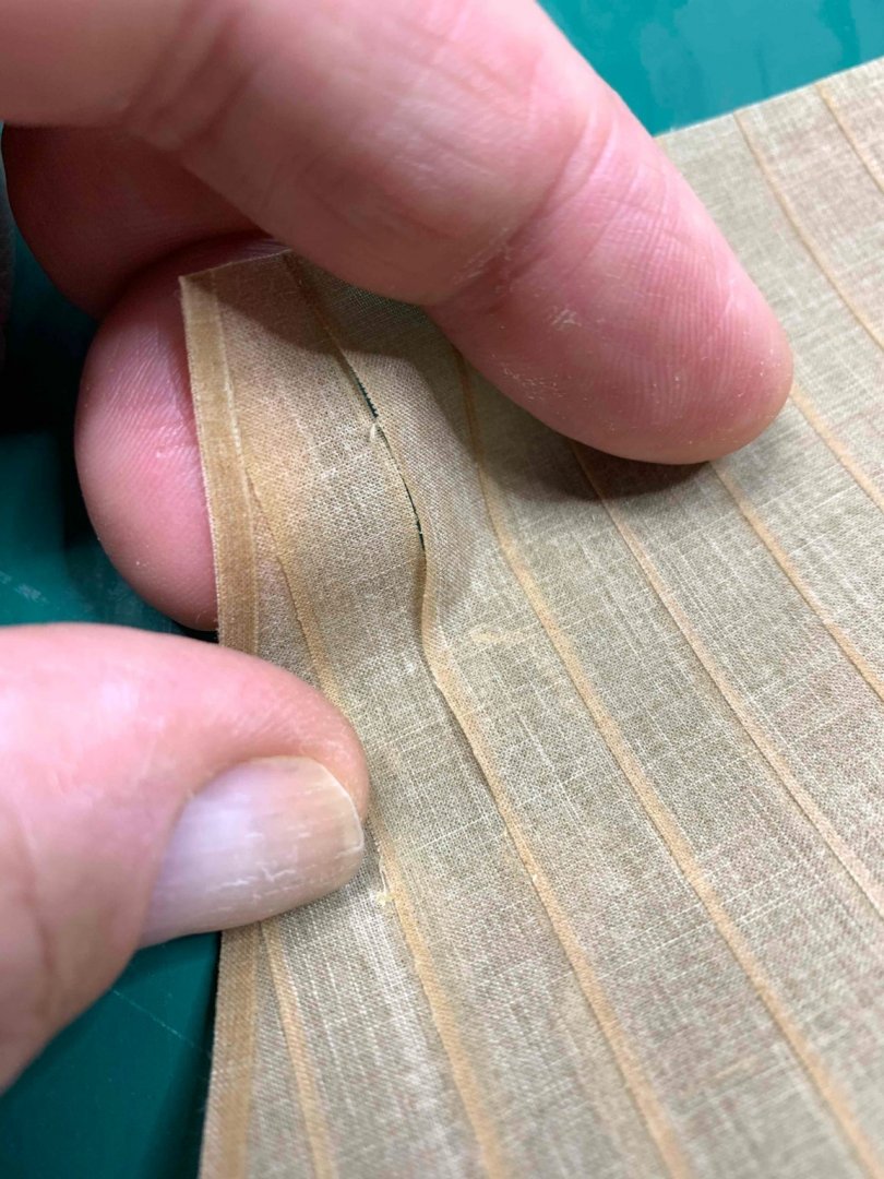
Still need to practice this technique, mostly on some bigger scale model... It turns out that with this way the amount of sail cloth provided in kit might not be sufficient. Also needs to practice on type/amount of glue used to glue strips together to simulate joining of two cloths.. Anyhow, the new material was located and in this case i will try simulating with a pencil line... I will also practicing with another sail cloth material and using "pulling the threads" technique for simulation overlapping seams.. Tracing the sails down... Simulating overlapping seams.. Cutting strips that will be glued to the sail.. In order to protect the cloth from starting to tear apart, the cloth for strips was covered with diluted white glue, 50/50 with water, left overnight to dry and ironed before used. Then it was placed down, with material threads as vertical as possible. Then i put several strips of transparent scotch tape to prevent tear, very much the same reason of putting the scotch tap on veneer before cutting it...The strips are cut 3mm and 4mm wide. I started with the longest run first... following the sail template.. I used white glue, not diluted to glue strips to the fabric. The scotch tape is pulled off easily once the glue settles down. The sail is cut off.. The simulation lines have to be put on the back as well.. Two lines of scotch tape with measurements are put on the desk and the lines are run on the material.. Running out of strips and making the new bunch described above.. All sails completed. Now it is time to run a boltrope, 4mm thick, using combination of cyano glue for a quick grab/hold and 50/50 diluted white glue running with the line, to make sure rope stays on.. Will continue tomorrow. Happy modelling...


- 275 replies
-
- 2
-
-
- phoenix
- master korabel
- (and 1 more)