
NavyShooter
-
Posts
692 -
Joined
-
Last visited
Content Type
Profiles
Forums
Gallery
Events
Everything posted by NavyShooter
-
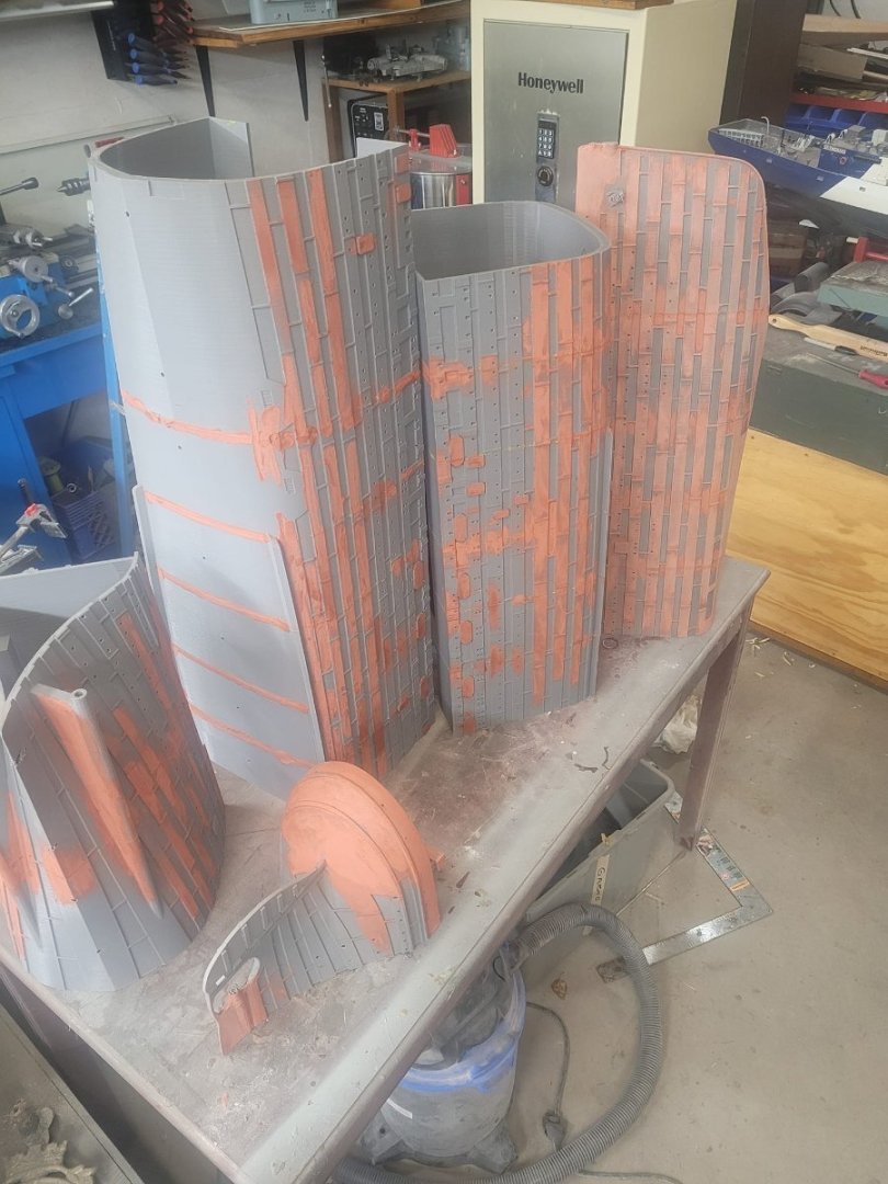
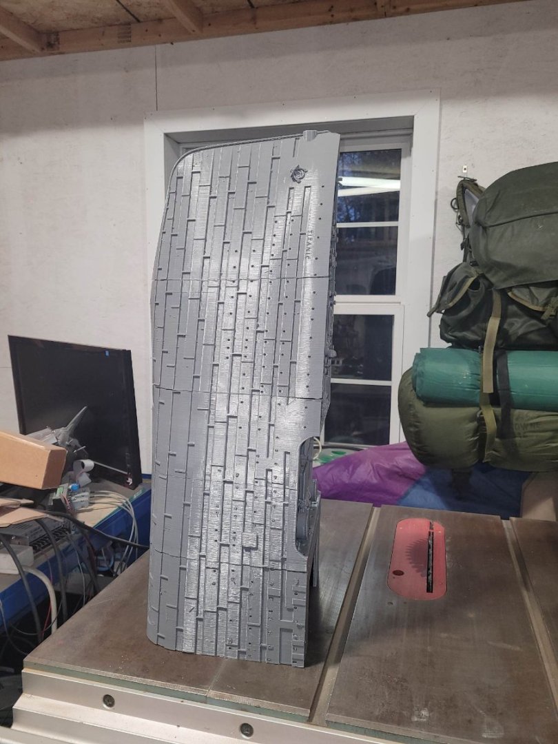
 OK, a bit of progress to report...the 3 forward 'module assemblies' have now been glued together.
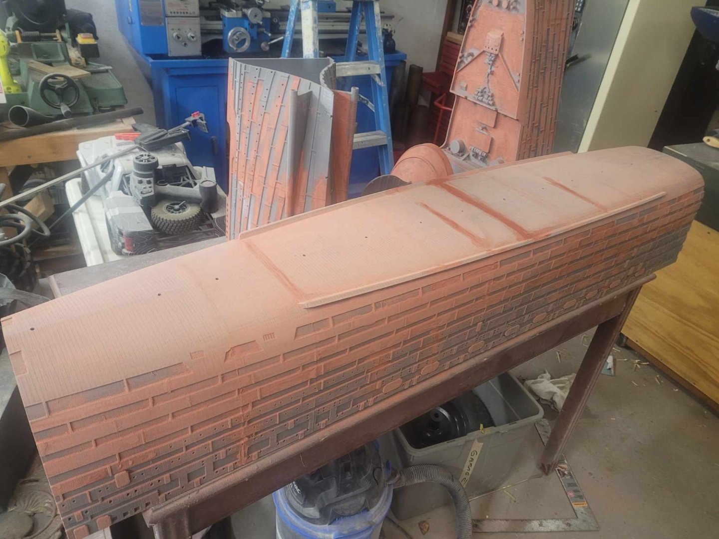

-
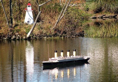
Of note, this was a picture of the original model a few years back. You can see that the original was quite detailed, had rigging, and was a favoured spot for at least one gull to hang out. Also, if you zoom in on this link in G Maps, and turn on the satellite imagery, you can see the spot amidst the lily pads where the Titanic model usually floats. https://maps.app.goo.gl/gFegbovZY3Ttc5ne9

-
The plan for the build was that I was to do the printing, and would pass it on to another guild member who would do the assembly and painting. He started by assembling some of the modules into basically 4 larger sections. Alas, the best laid plans seldom work out, and that member took a year long contract in another province, and dropped the model back to me to work on over the winter. The time has come to start that work. The Guild has a model show in a couple of weeks, and I'd like to have something on display to show off. So, step 1 is to get some putty on the sections, and smooth some surfaces. Next will be to add a layer of fiberglass resin and start sealing things up.
-
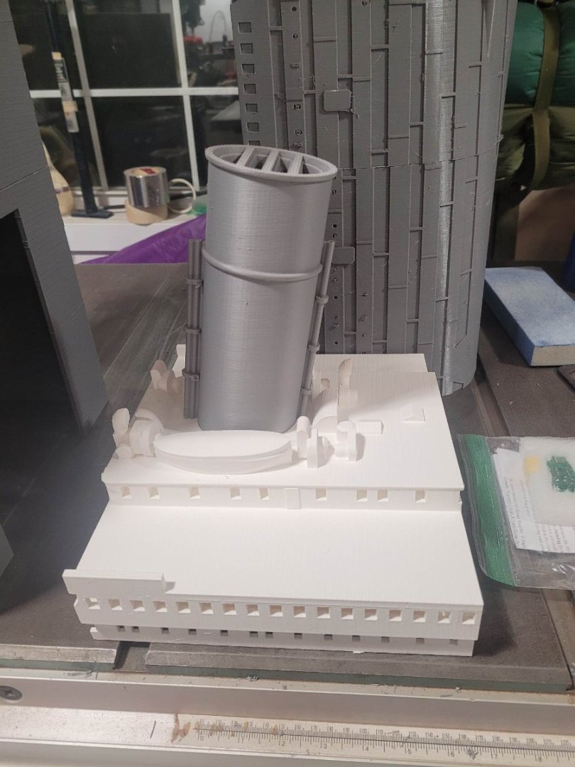
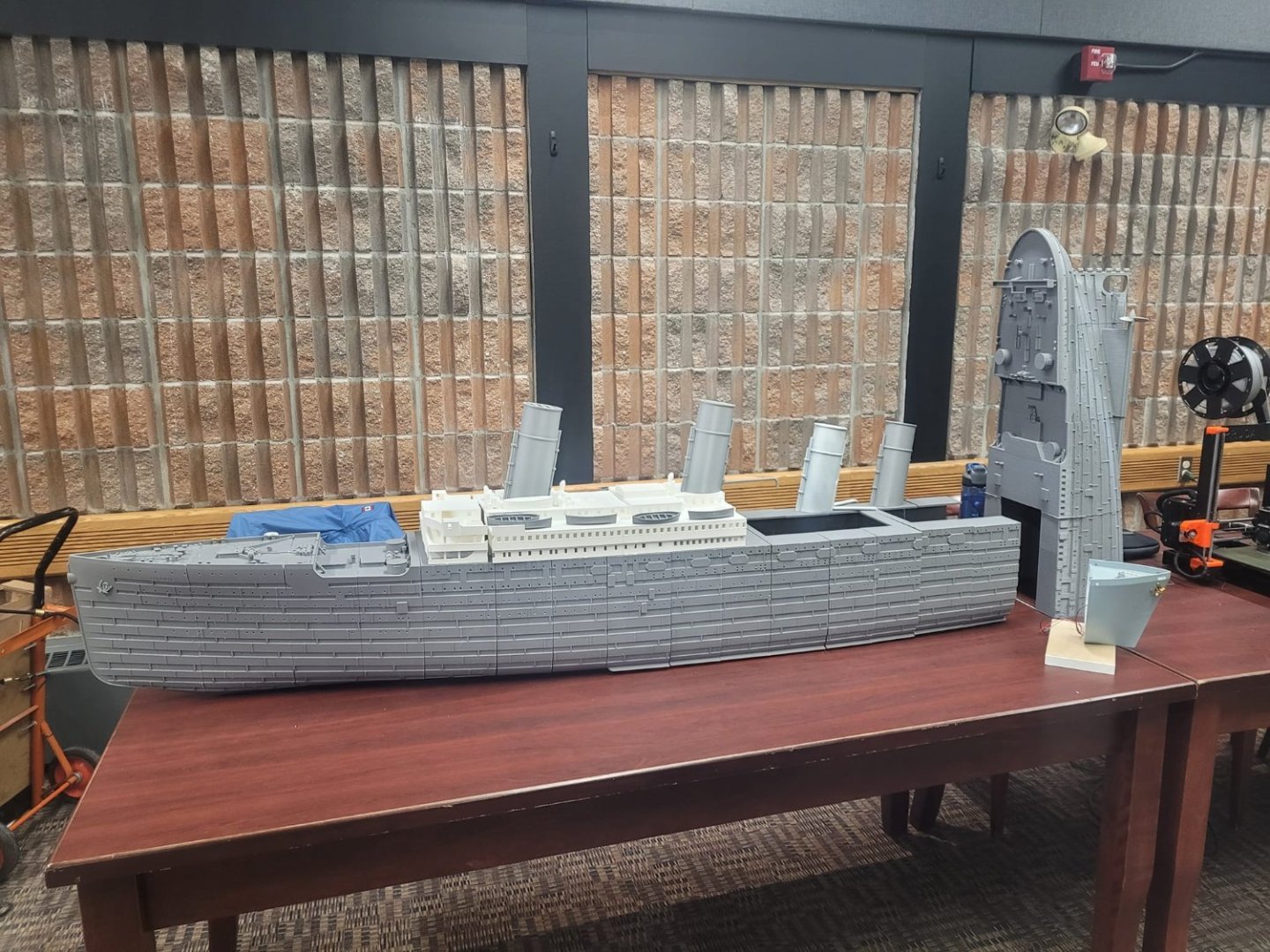
Here you can see some images of the hull - some of the modules took up to 50 hours to print. If you recall my build of the HMCS St Thomas, I used the same printer, so there are some of the same minor print flaws in the hull. I'm not stressed about it, that's what putty and fiberglass resin will hide. The superstructure was originally sent with all the windows open, so I asked that the designer re-do it with the windows sealed up inside. That took him 10 minutes of work...it would have taken me hours to seal those from the inside if I'd had to do it on the model itself. You can see the level of detail is quite good. It will far exceed that of the current model, and I think it will meet the goal. For reference, the cost of the PLA to print this was about $475 Cdn.
-
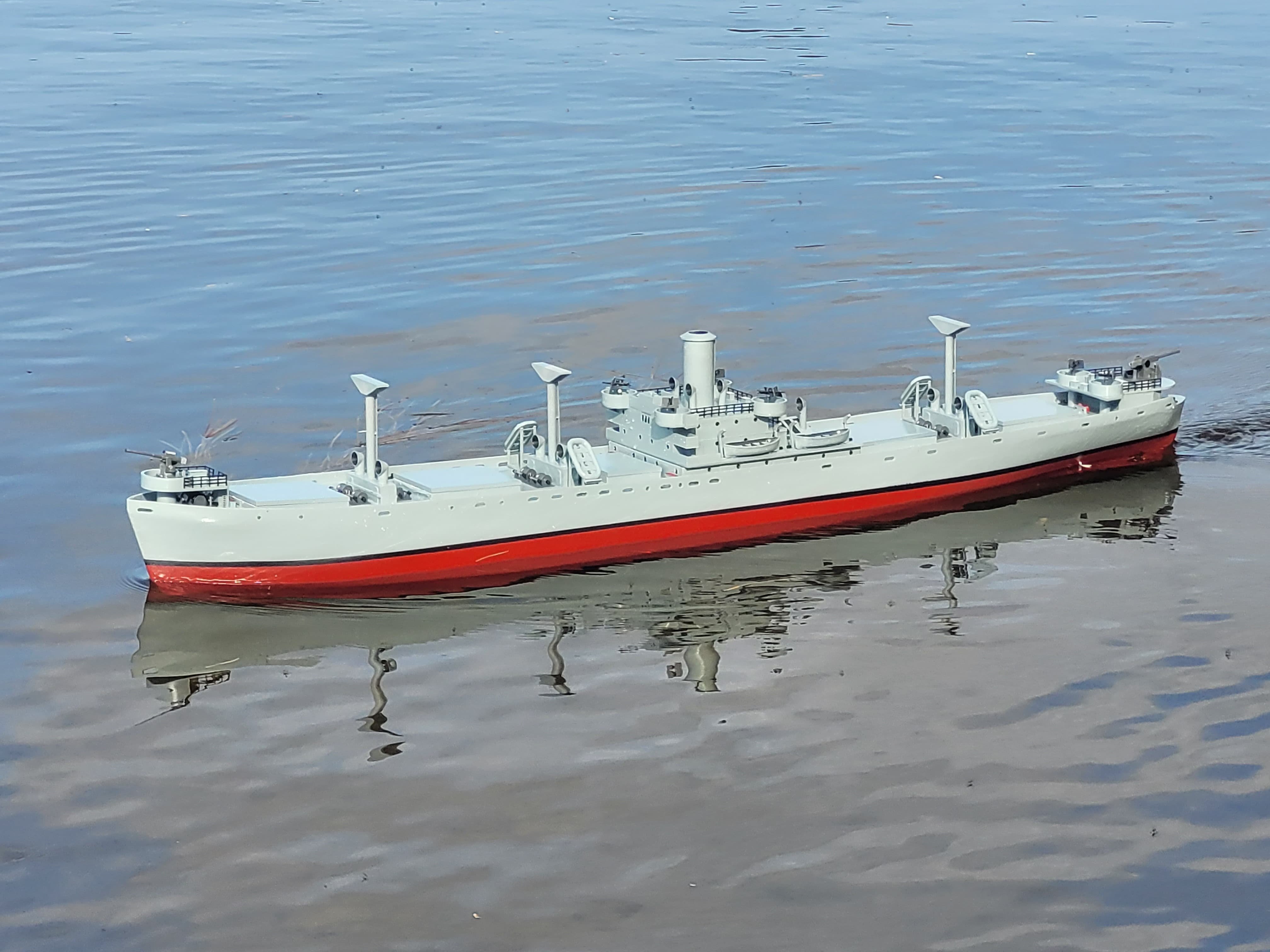
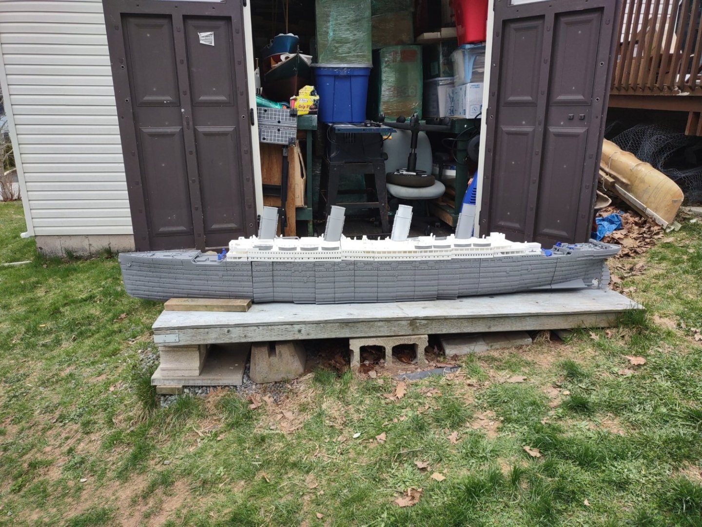
This is NOT destined to be a highly detailed model. The Guild built one of those a few years ago which is on display at the Maritime Museum of the Atlantic in Halifax. Here you see some finishing touches being applied to that model. I think it was about 1/200. This model will be a slightly better than stand-off scale model, with some detail, but most of that will be invisible due to the model being in the middle of the pond, rather than behind glass. It must first and foremost be durable, reasonably accurate, and able to survive hopefully many years of immersion in a duck pond, with it being launched in May, and pulled out in October. It must be black/red/white/tan, and must be a good visual representation of the RMS Titanic. It does not need rigging, or super detailing. It needs to be able to survive a duck landing on it. I intend to include a small interior water pump, in case there is any leakage. (Solar powered) I also intend to include an LED flashing element, signaling SOS. (Battery powered, solar charged.) The hull is printed of PLA, will be covered in Bondo Fiberglass Resin on the outside, epoxy paint inside, and will have a metal keel strike plate both inside and outside to support, and act as ballast. Our estimate is that this model will need to weigh close to 200 pounds to sit at a scale waterline.

-
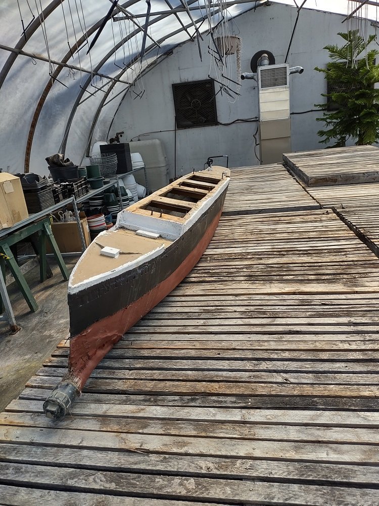
Ahoy Gents! The other ongoing RMS Titanic build has me inspired to start a concurrent thread... The Maritime Ship Modellers Guild in Halifax NS has, for many years, had a good relationship with the city parks folks, and you can see the image below of the RMS Titanic Model that spent many years in pond at the Halifax Public Gardens. That model was retired about 5 years ago, and a replacement was slapped together. The replacement was not built as well as the original. The original lasted 15+ years, the replacement sank last fall, and spent the winter on the bottom of the pond. You can see the image of the model as recovered (after having the duck poop rinsed off) and a well meaning member of the Guild did some quick repairs on her to get her back in the pond this summer. Alas, the repairs did not take, and she started sinking again. and was pulled out of the pond and put back in storage. As a group, we decided at our March meeting to go ahead and build another Titanic. I offered to investigate 3D printing one, and that is the path that we chose. I engaged with a designer, and he modified one of his 1/1000 scale files to suit our needs in 1/100 scale. The printing started in April, and finished in May. Ish.
-
Perhaps the right term is "sea chest" or "sea bay" for a water inlet.
-
That is 2 sheets of styrene - a 2mm and a 3mm, each one 8 feet by 15 inches. When I get time next week, we'll see if the 2mm is going to be stiff enough...or if the 3mm will be light enough.
-
Looking for an Anchor Winch - RC Boat
NavyShooter replied to NavyShooter's topic in RC Kits & Scratch building
STL file RC Anchor winch freefall・3D printing design to download・Cults (cults3d.com) There's another option - 3D printed solution for you. Requires 2 channels though. -
OK, so, with a bit of a delay in production due to...well...life...(Austin for F1 racing with the family, plus a couple of weekends working with the Army Reserves) I'm starting to line up to get things on track again. Piedmont Plastics in Dartmouth NS has 2 and 3mm thick Styrene plastic sheets (4x8 feet) in stock, at $48 and $96 each respectively. So. I've ordered a sheet of each to bring home. I am thinking that the 2mm might work, but might be subject to some warpage. I'm thinking that the 3mm would probably work, but might be too heavy. So. I'm buying both and they'll have them cut to 'size' for me early next week. Good news is that I've got a pick-me-up-truck so I'll be able to carry them home easily.
-
Interestingly, the same 20mm Gatling is found in the shipboard CIWS...and they all were evolved from the army AA version that was mounted on the M113 APC back in the 60's.
-
Looking for an Anchor Winch - RC Boat
NavyShooter replied to NavyShooter's topic in RC Kits & Scratch building
He had a face B ook page, but he closed down a few months ago. -
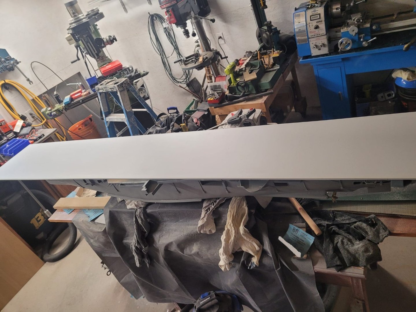
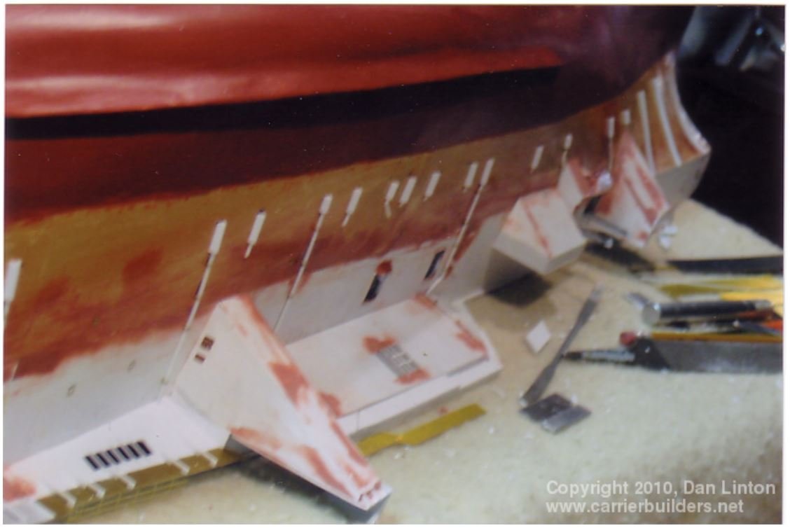
And, one last problem...here's the flight deck overhang... You can see that it's sagging quite a bit. I visited the old Carrier Builder's website, and referenced the photo of Don Linton's beautiful model to see what his looked like underneath the overhang. I think my solution is going to be to add a wedge underneath that lifts it up whilst pressing on the hull side...that looks 'right'. Ish. We'll see. This one's going to take some thought to figure out.
-
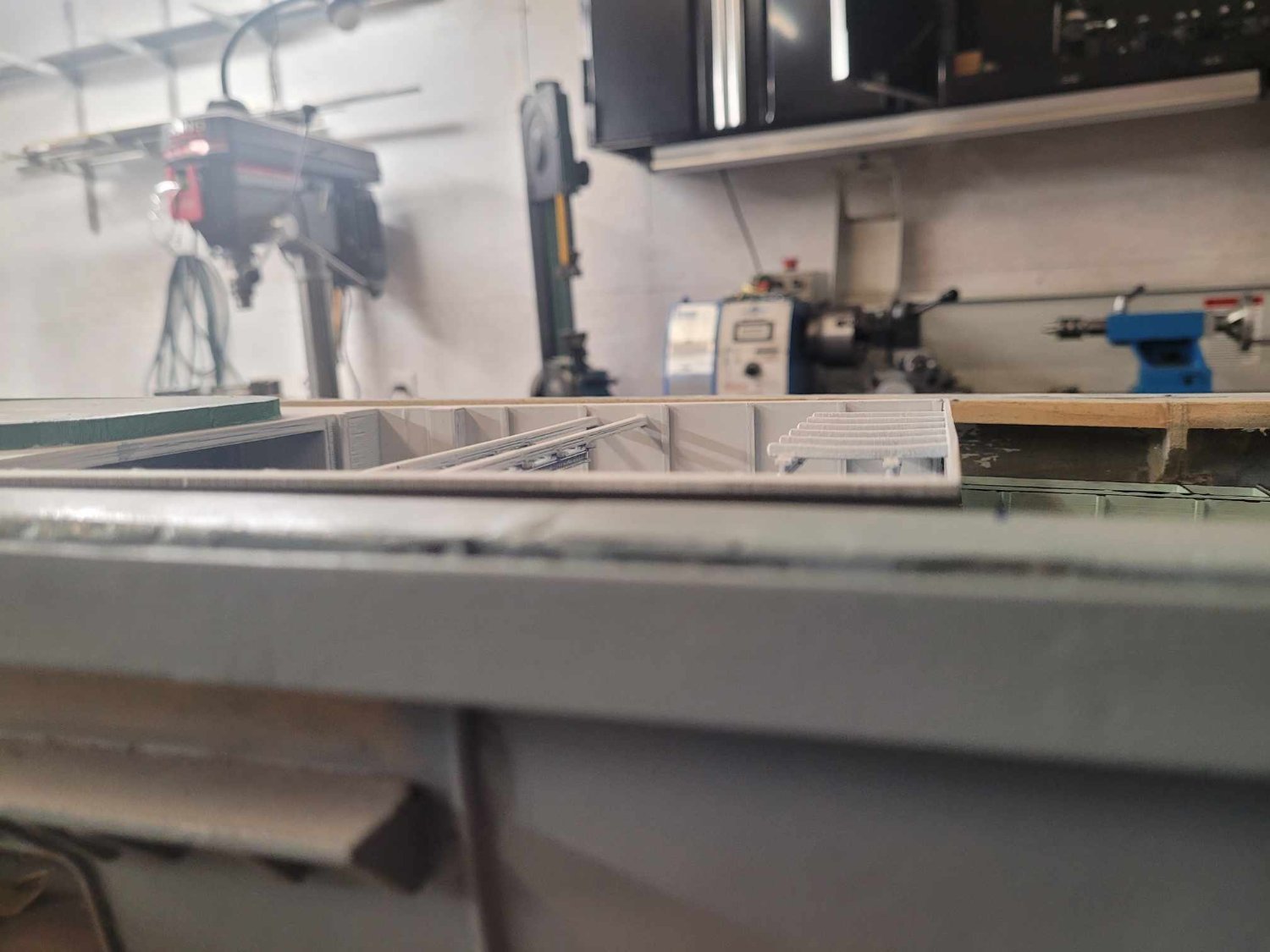
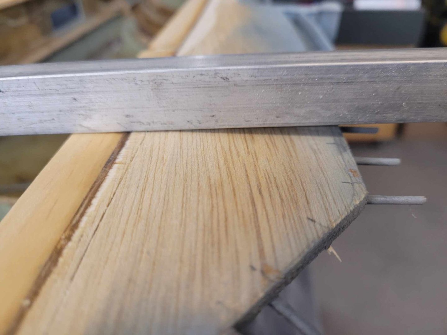
OK, I'm pursuing the plastic solution. I bought another 1/4 sheet of plywood, just to see what it'd look like, and while it was straight-ish in the store, it was not by the time it got home...so...one of those companies listed offer a sheet of 1/8" styrene for $100 - I think I'll be buying that when I get home from vacation (going away with the family for a few days next week.) In the meantime, I identified ANOTHER problem...the upper surface of the hull where the flight deck sits on is...well...not flat. So...here's a few images of me doing a bit of sanding to sort that out. Once I finished up with the sanding, I gave it a quick shot coat of clear coat to seal things up. Way too much warpage going on....


-
So, I had a couple of buddies over last evening and we had a chat about the flight deck. The wooden boards of the existing deck were always a bit wavy. Well, when I sectioned it last week, things really went wonky, and at this point, I think it's beyond recovery. 30+ year old plywood is not reacting the way it should...I don't know if it's moisture or what, but it's gone completely whacky. The stern section has a 2 inch warp in it now - previously it was about 1/2 inch or so, which I thought would tame down and be workable. So. A new flight deck is in order - the question being - what's the right material? My buddy suggested plexiglass for the whole deck. And that's actually tempting, except for the weight. Do I go with plywood again? Thoughts from the hive mind of modelers? NS
-
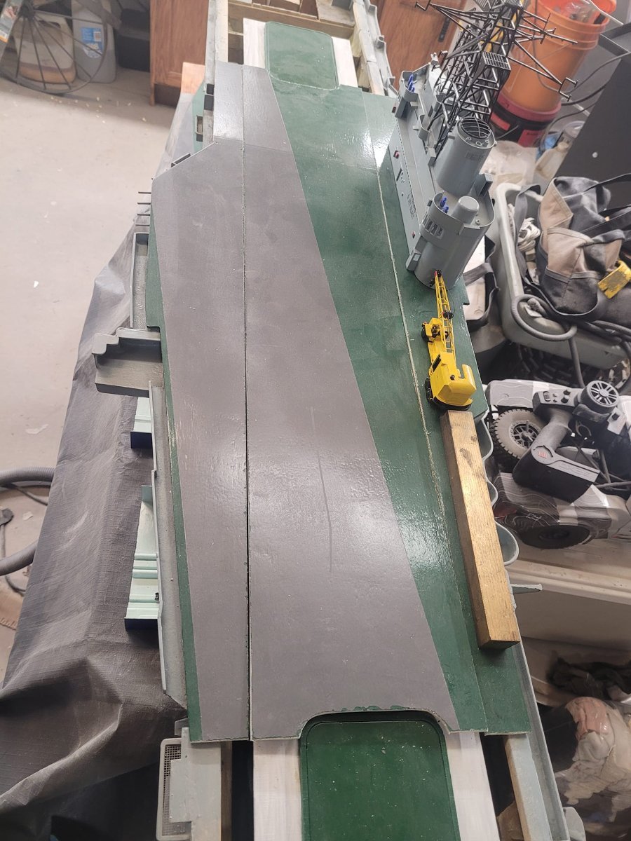
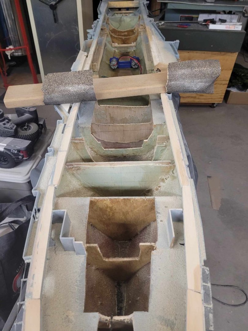
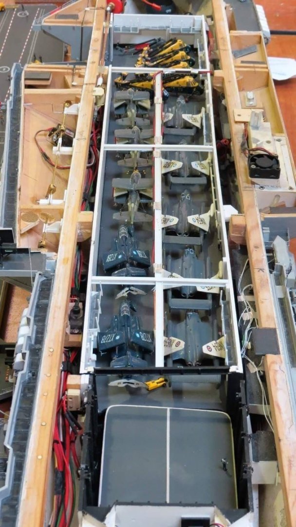
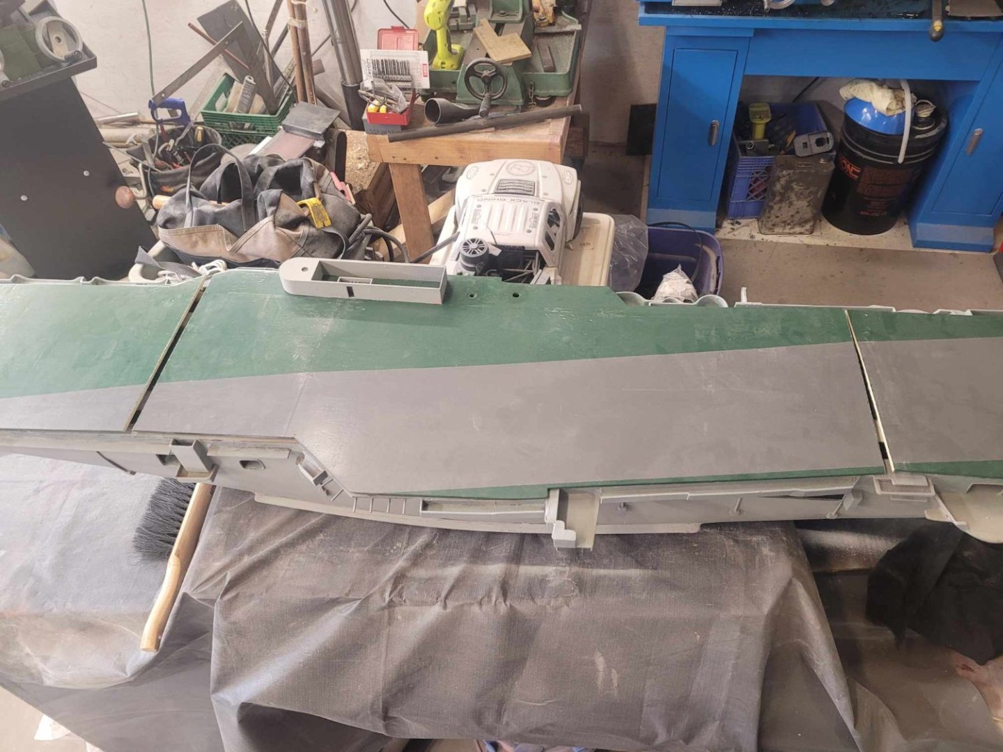
A bit more progress this evening, and a comparison between the inspiration from last year, and what I've got going on as of this evening: I've got the main center piece of the flight deck sliced up and fitted between the elevator risers.

-
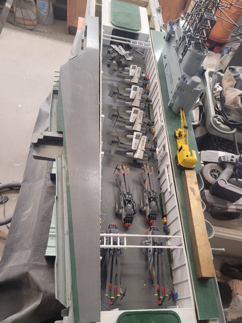
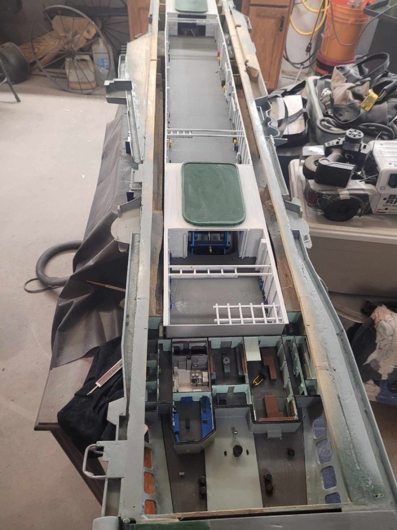
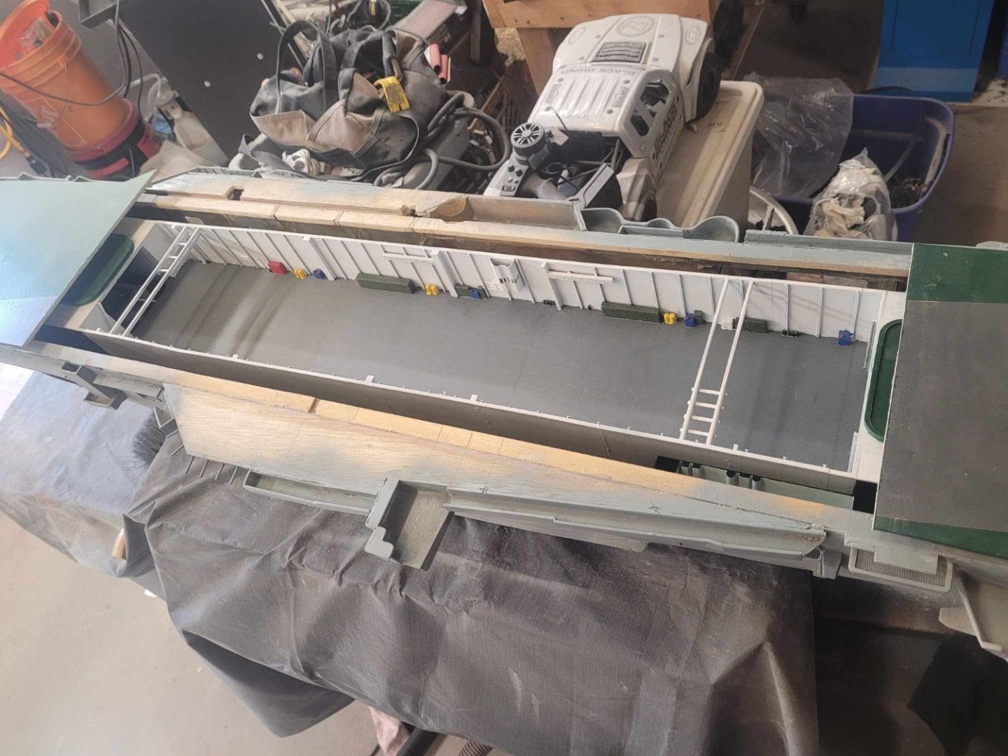
OK, a bit more work this evening and I've got the hangar deck resting on blocks at the correct height within the hull so that it sits flush with the deck. Quite pleased with how things look at the end of the day. This is, literally, a year in the making. One year ago last week, I posted this (back on page 4) and as of today, I am pretty much where I want to be. with this.

-
Here's the chopped up deck. I have to center the hangar properly in the hull, then I'll start cutting things a bit more for the insets. NS
-
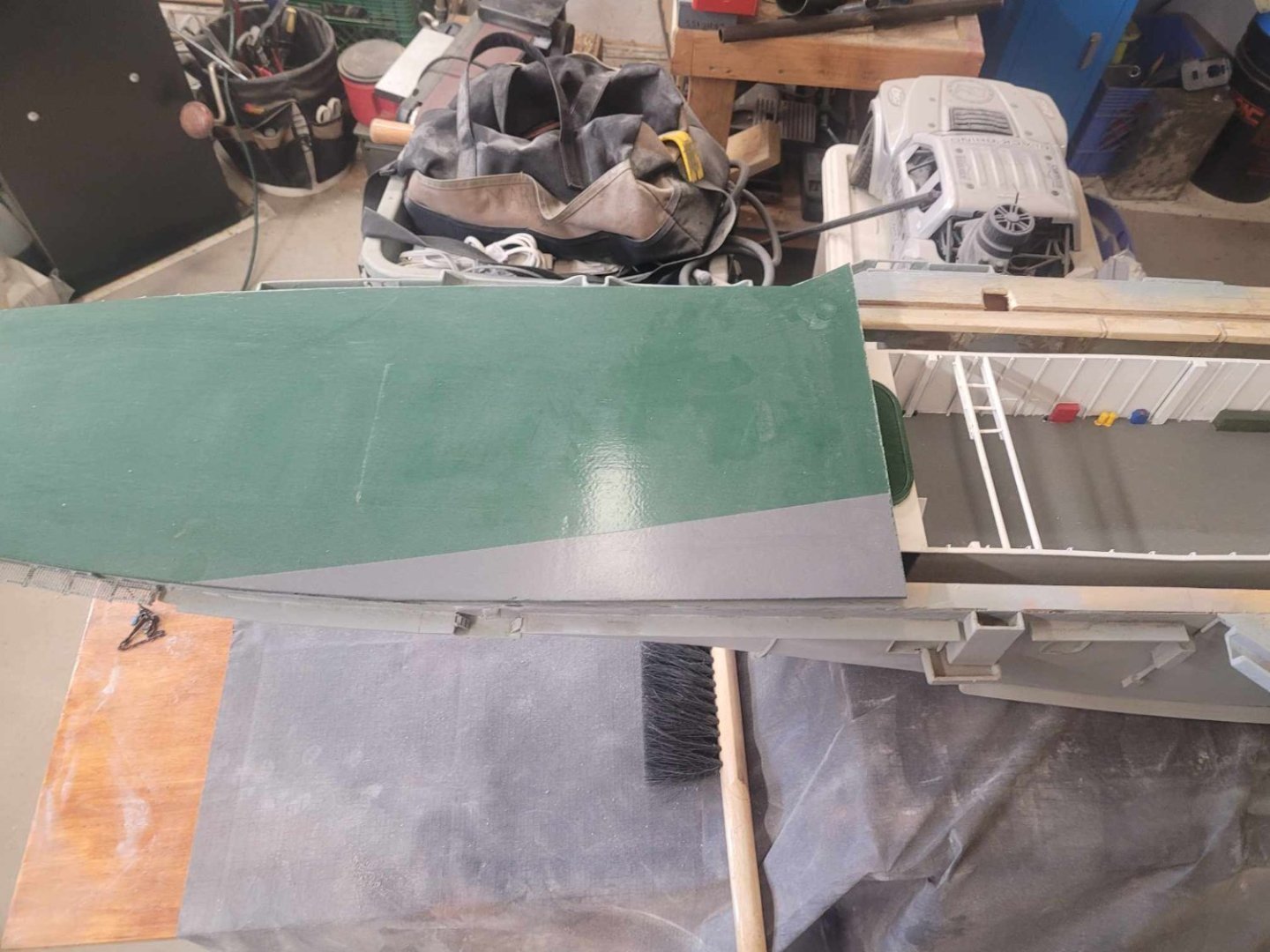
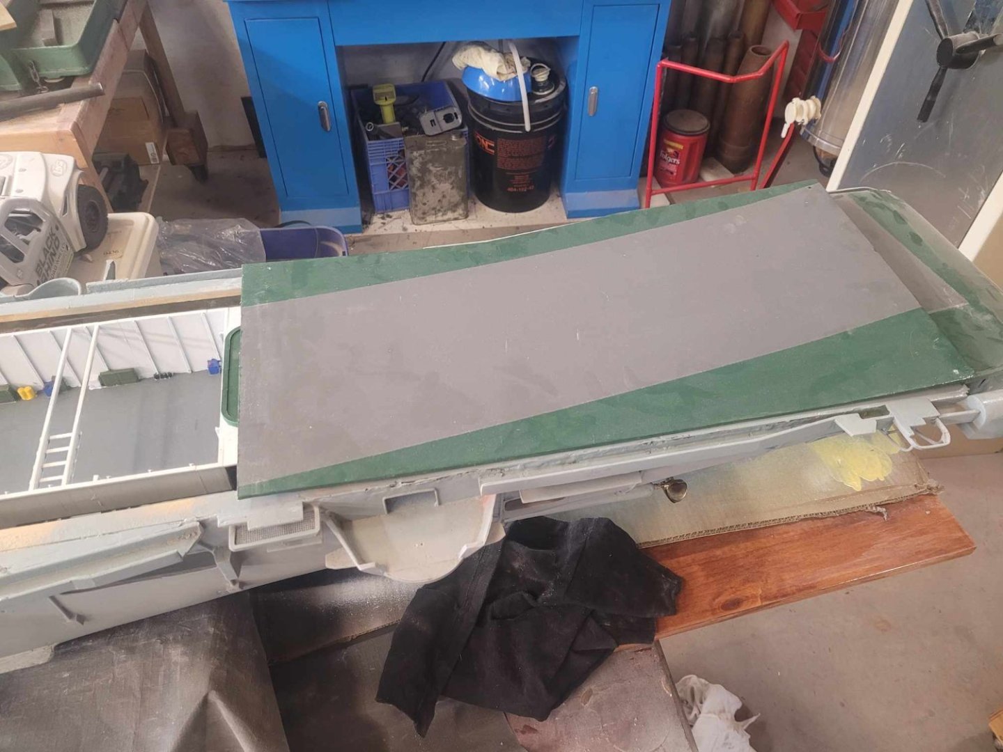
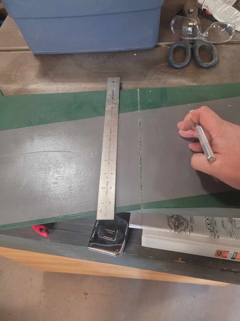
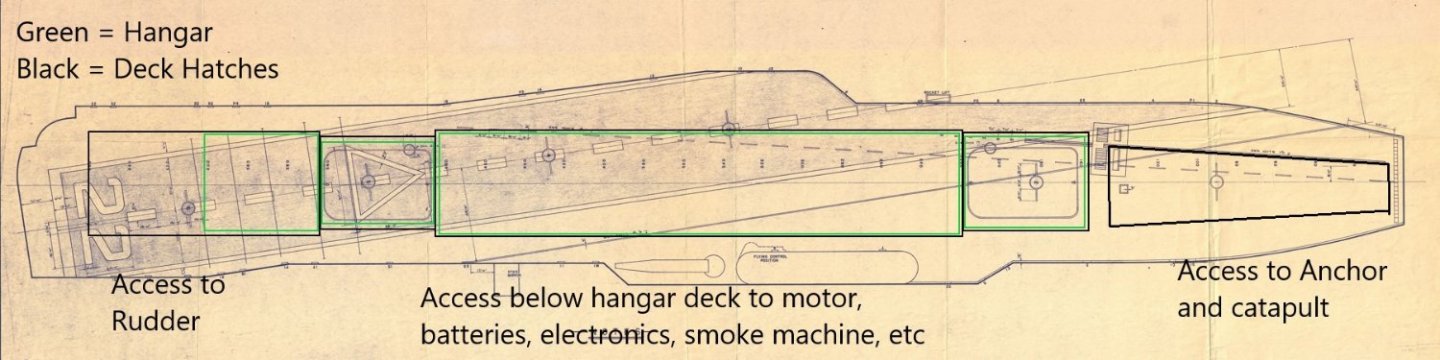
OK, so, next step is the Deck Access Plan....to start this, I started with cutting the existing flight deck piece which I have into 3 segments to work with.
-
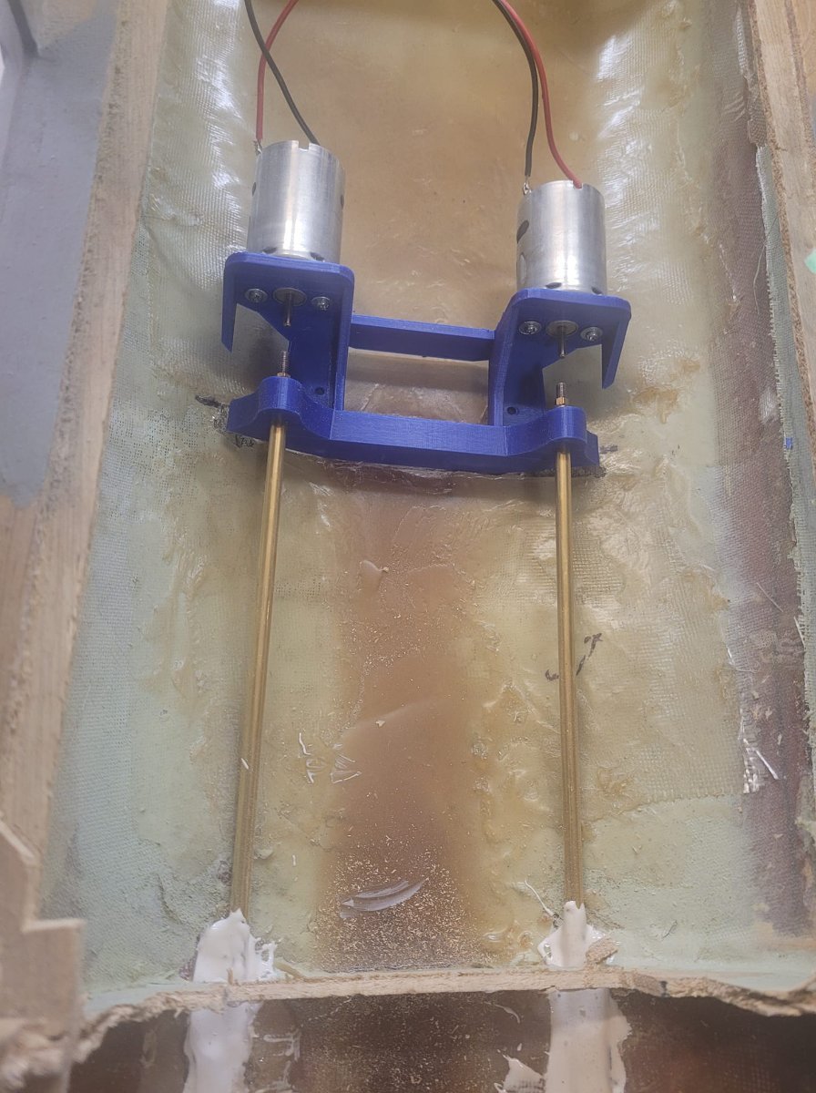
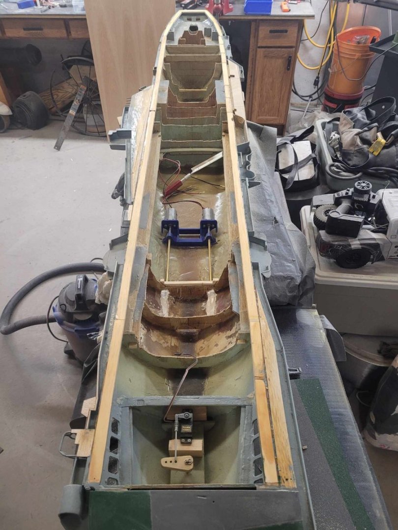
OK, I flipped her over this afternoon, and figured I should show off the motor mount too. Then I decided to spin the shafts - so, a couple of AA batteries made me momentarily happy...which led to digging out the ESC's and receiver - a few minutes later, I ended up spinning the props under proper power! I added a short video of that to the RC Aircraft Carriers face book page.

-
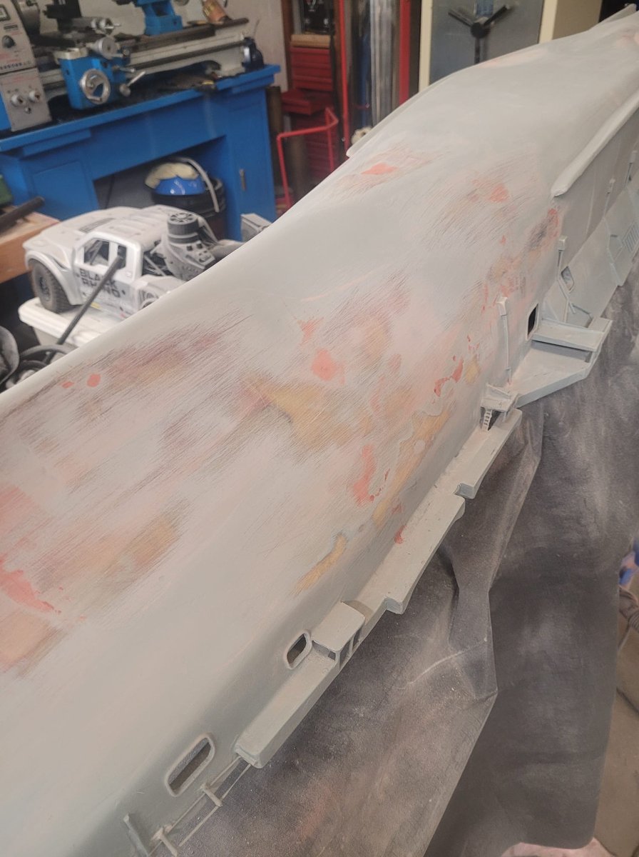
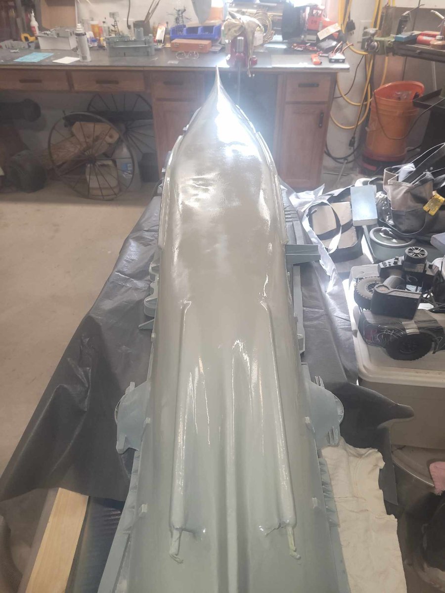
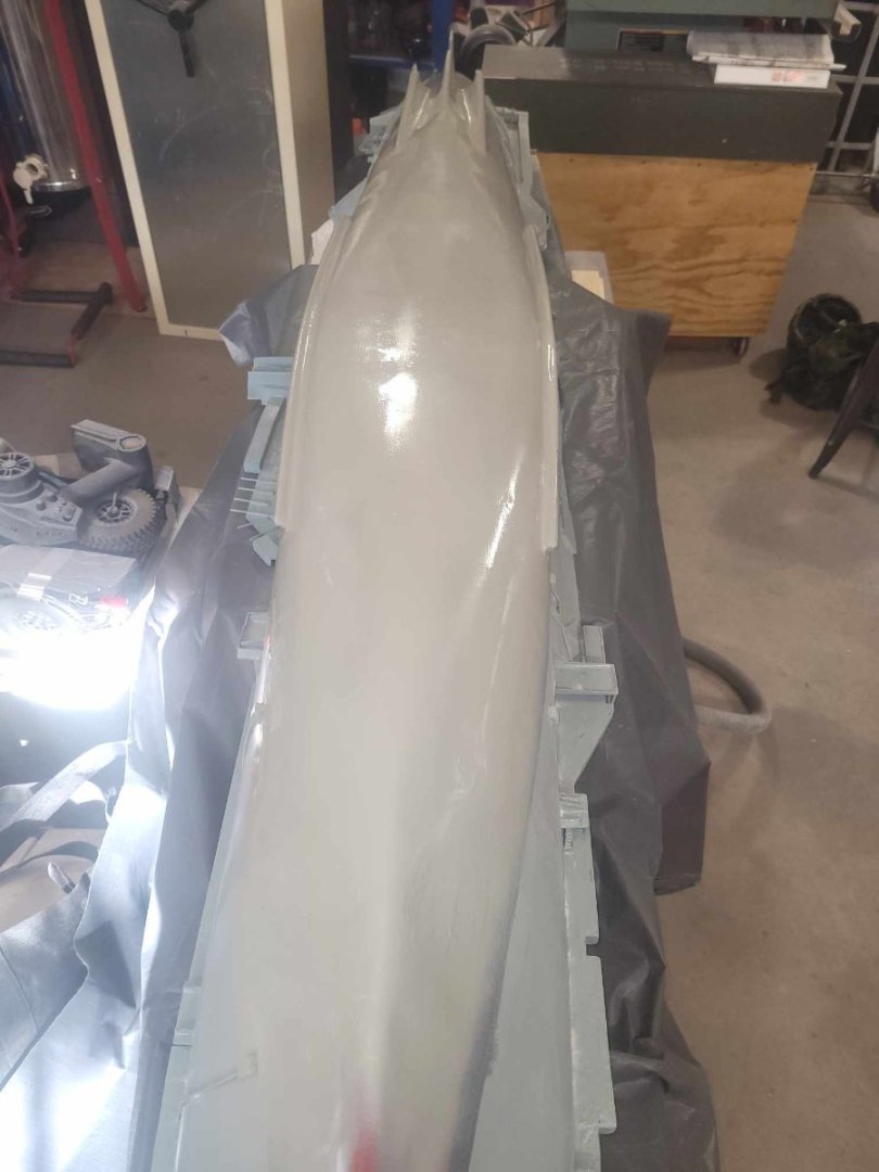
A little bit more work...one final touch up with spot putty, applied, sanded, and primed again. I think I'm going to call this complete. Shafts are fixed, hull is smooth(er) and I'm quite pleased with how she looks now. Almost time to flip her over and scribe some lines for the water line again.

-
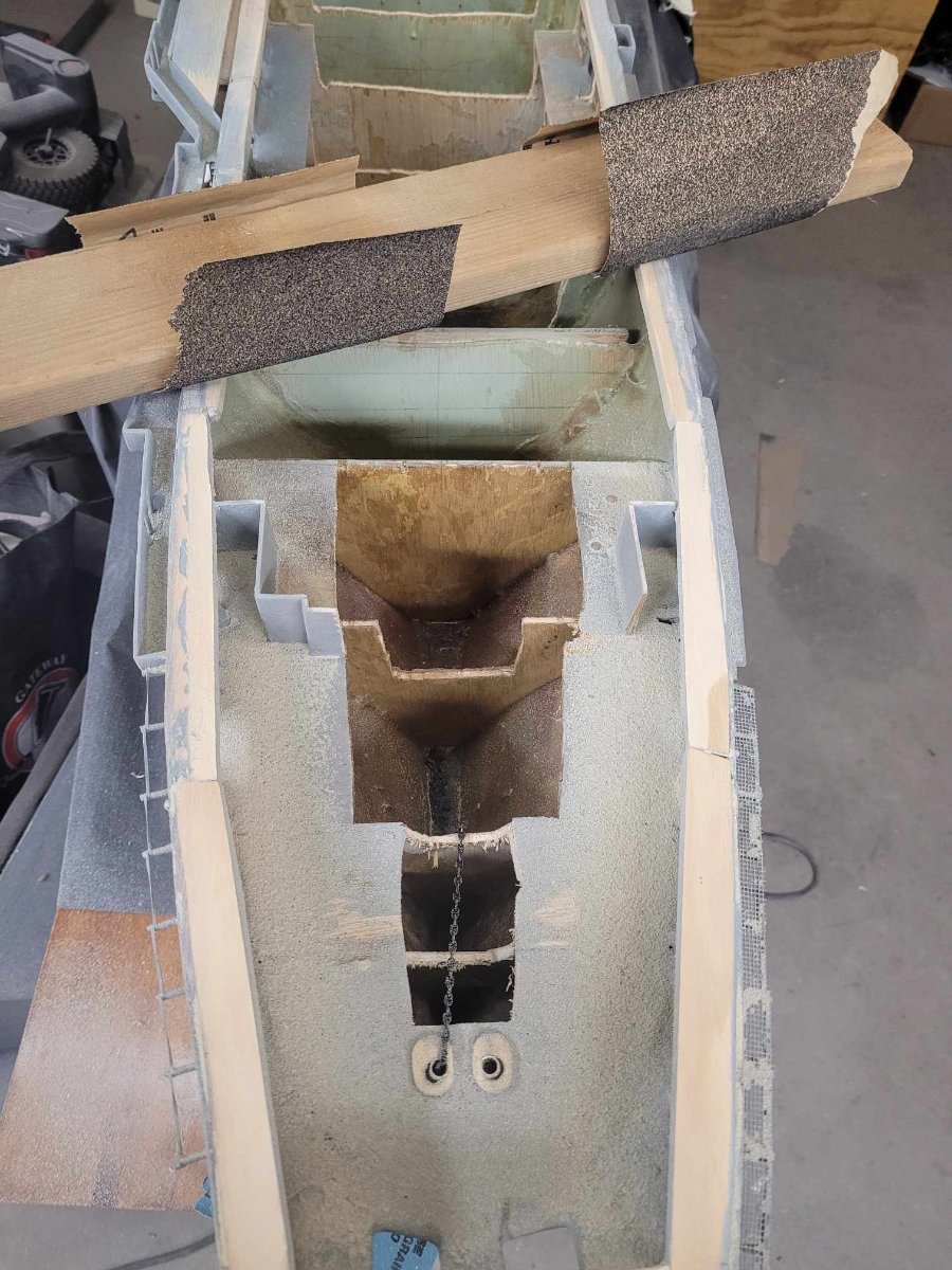
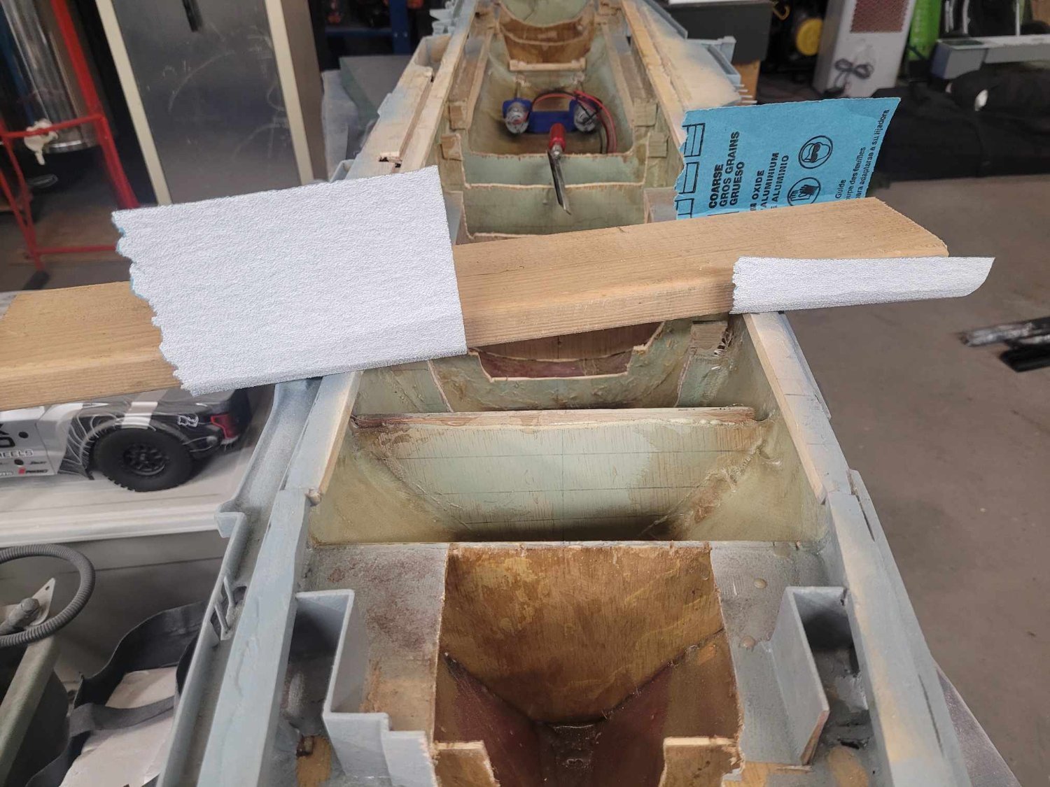
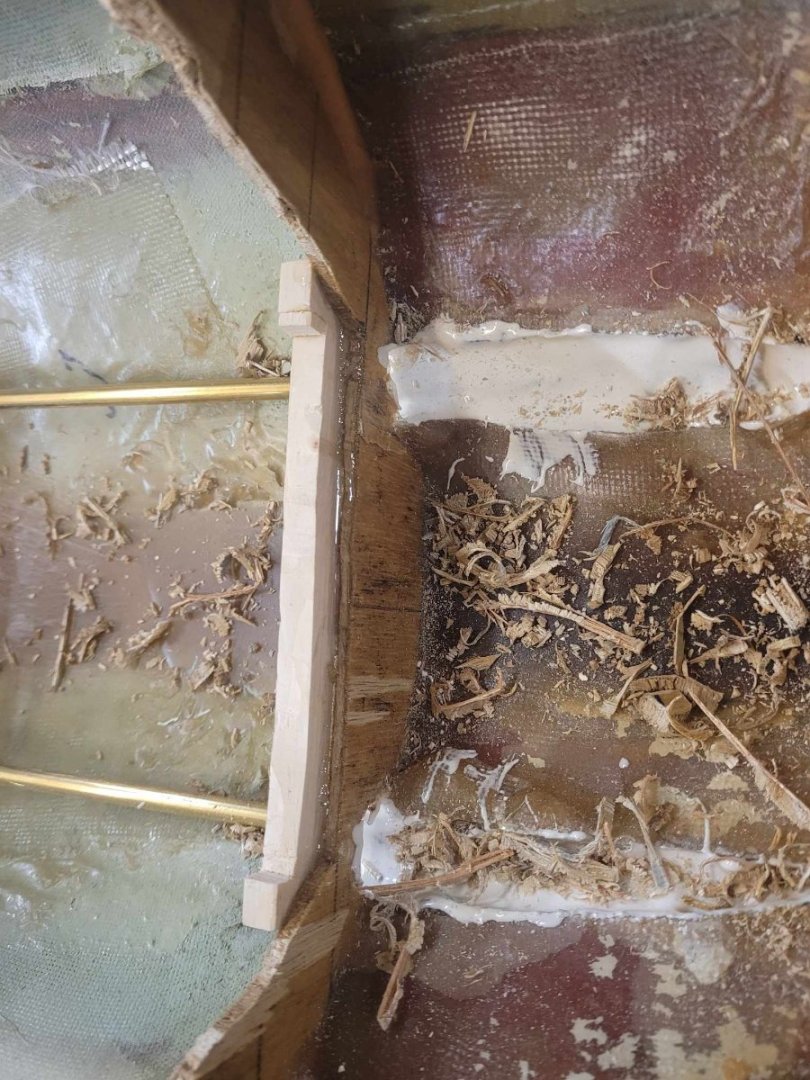
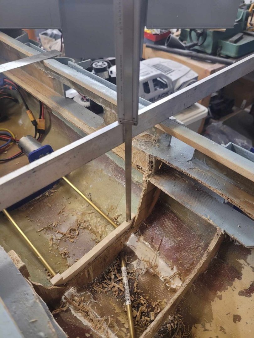
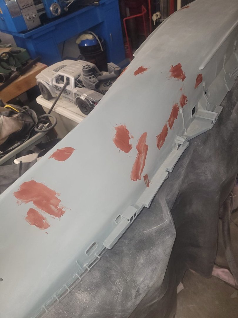
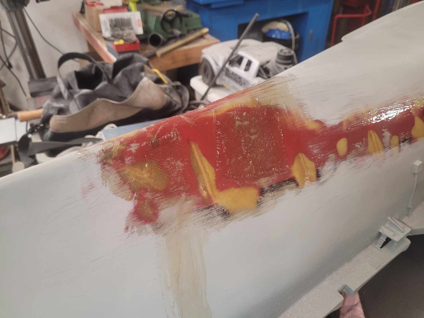
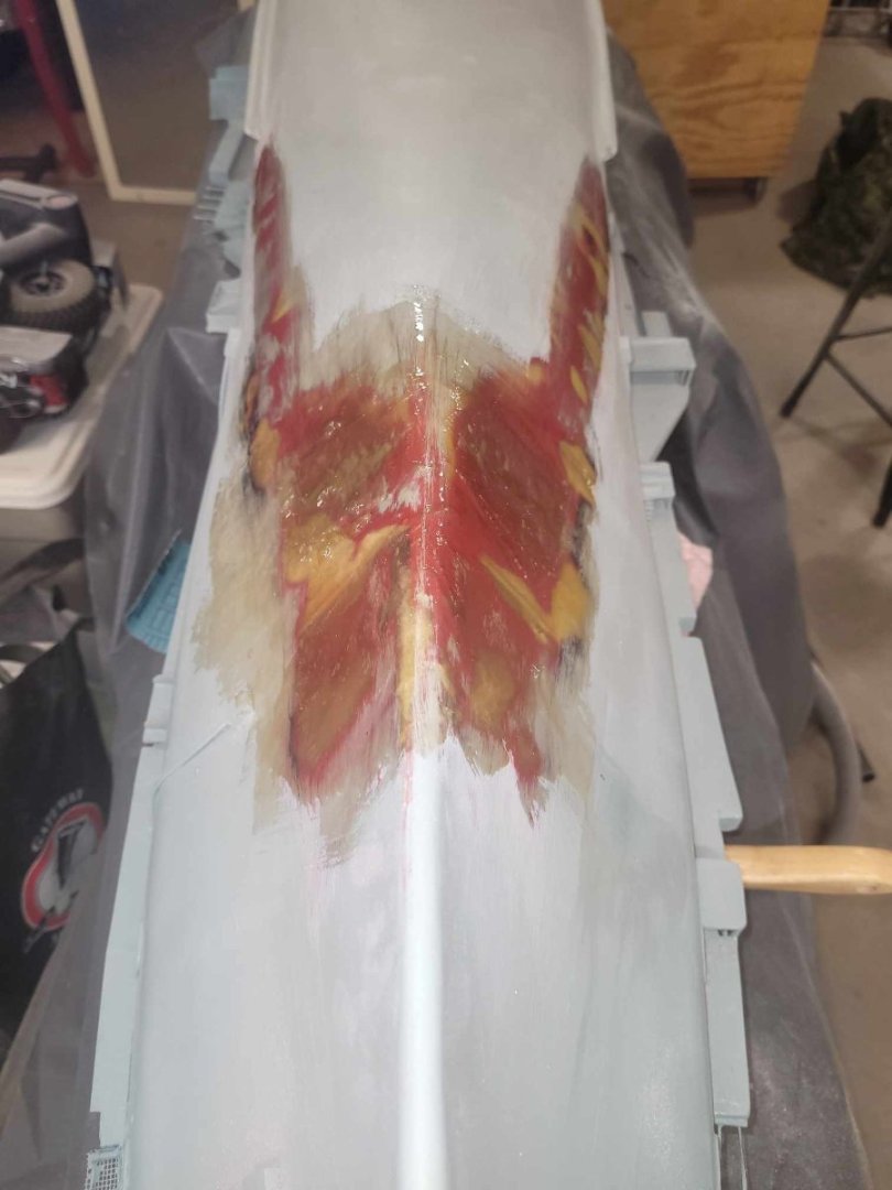
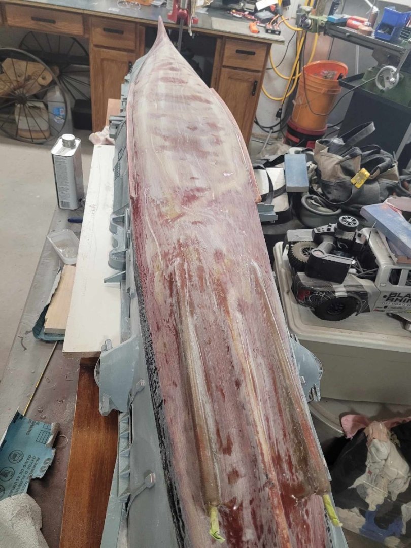
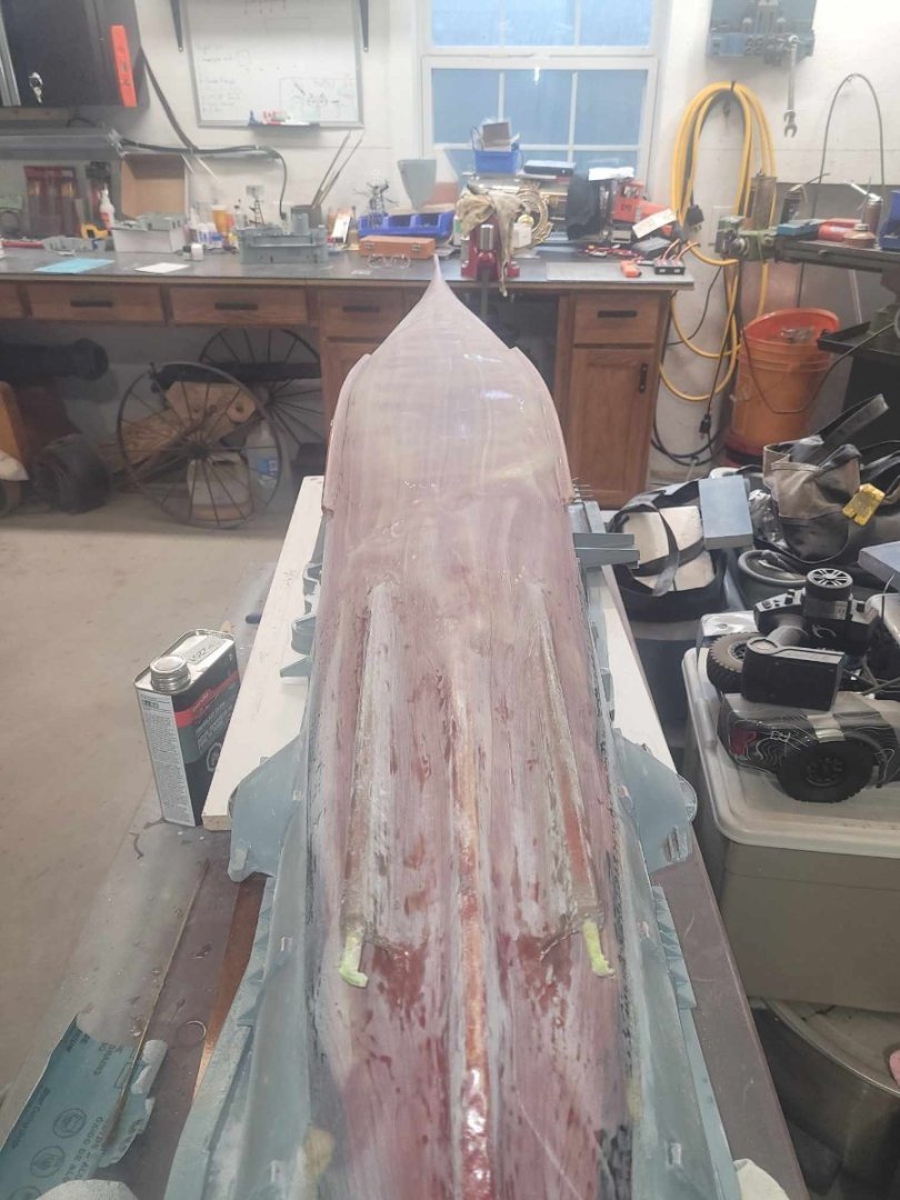
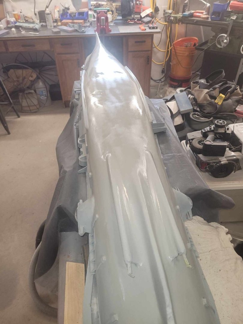
And....my OCD kicked in, and there were a couple of spots up at the bow that needed a bit more work. And I had to tidy up the rear parts of the skegs with a dremel...and...so....more fiberglass. What doesn't show well in these 'during' images is the way the hull was sunk in between the frames, so a couple of layers of fiberglass cloth were added to each of them. Hopefully it smoothes things out a bit. Probably need another layer or two of resin. Such is life....
-
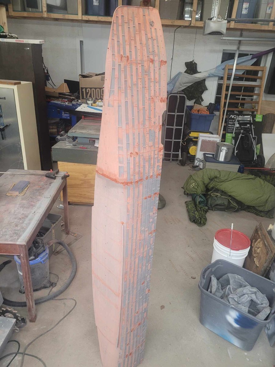
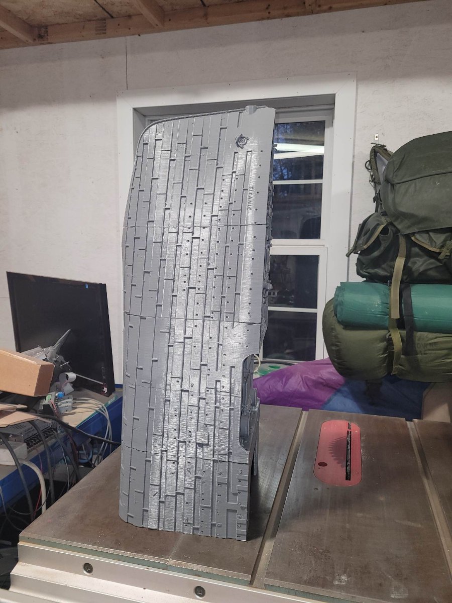
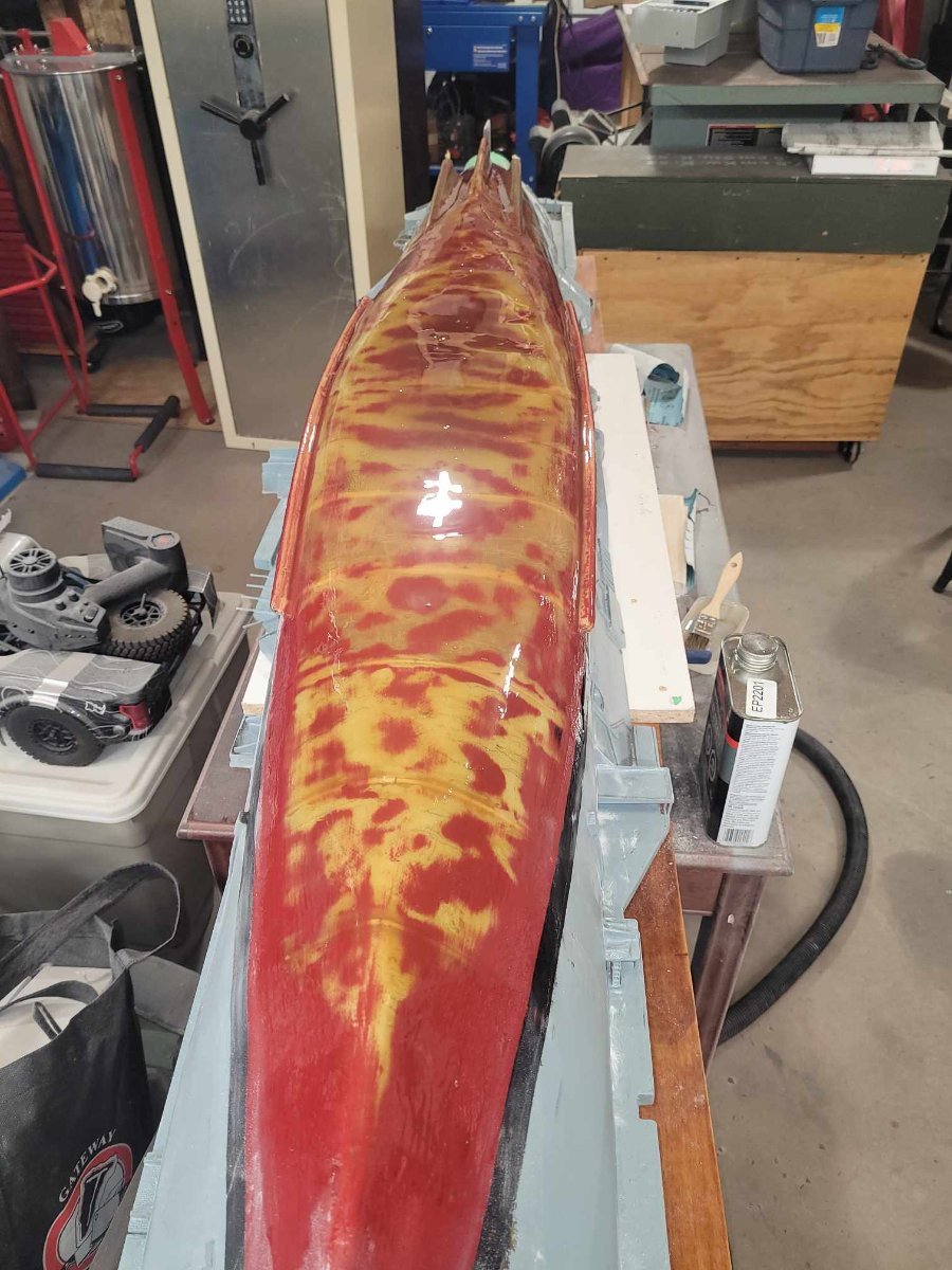
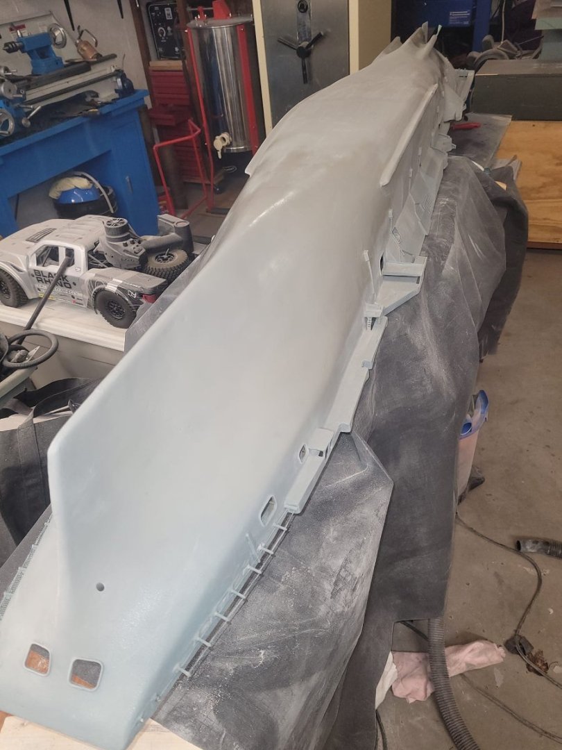
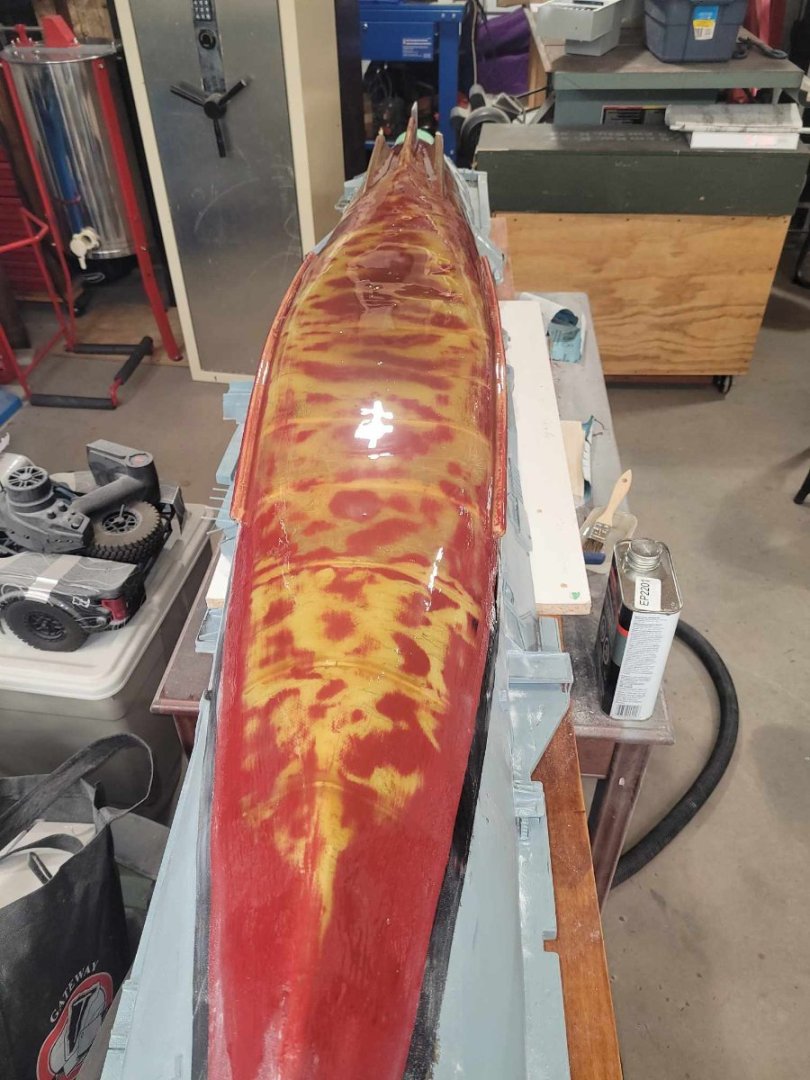
7 layers of resin later...I think I'm pleased with the outcome. Considering where it started, and where it's at now, this is a night and day improvement. In this image, you can see all the red splotches - those are the low points that I was trying to fill out. In this image, you can see the end result after the 7 layers of resin, and 2 layers of primer. I'm quite pleased.

-
P-38J Wicked Woman by DocRob - FINISHED - Tamiya - 1/48
NavyShooter replied to DocRob's topic in Non-ship/categorised builds
That is indeed a beautiful finish! Very well done! I am amazed at how the rivet lines turned out in the end. Absolutely amazing. -
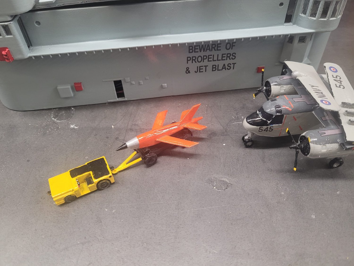
I also took the time this evening to put a layer of bright orange on the test target drone at last. Came out pretty good I think!