NavyShooter
-
Posts
692 -
Joined
-
Last visited
Content Type
Profiles
Forums
Gallery
Events
Everything posted by NavyShooter
-
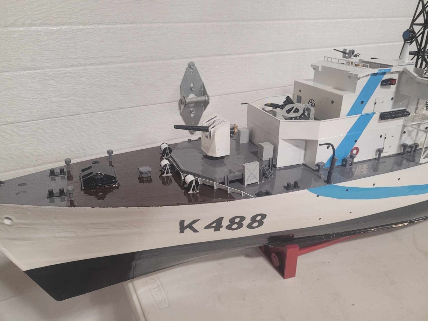
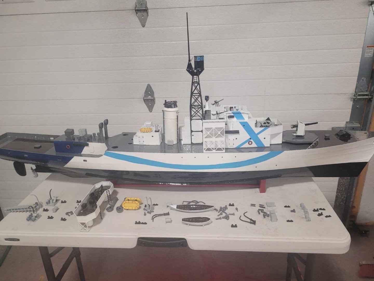
 All the bits are glued on....needs a few more items finished up... 1. Epoxy final coat (hull numbers and superstructure details) 2. Name plate 3. Glue on gun tubs and Funnel 4. Make hold down for bridge (seal to deck) 5. Float test - adjust ballast 6. Add foam inside to prevent sinking Then she's ready for the pond! NS
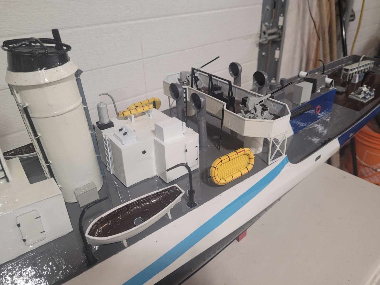

-
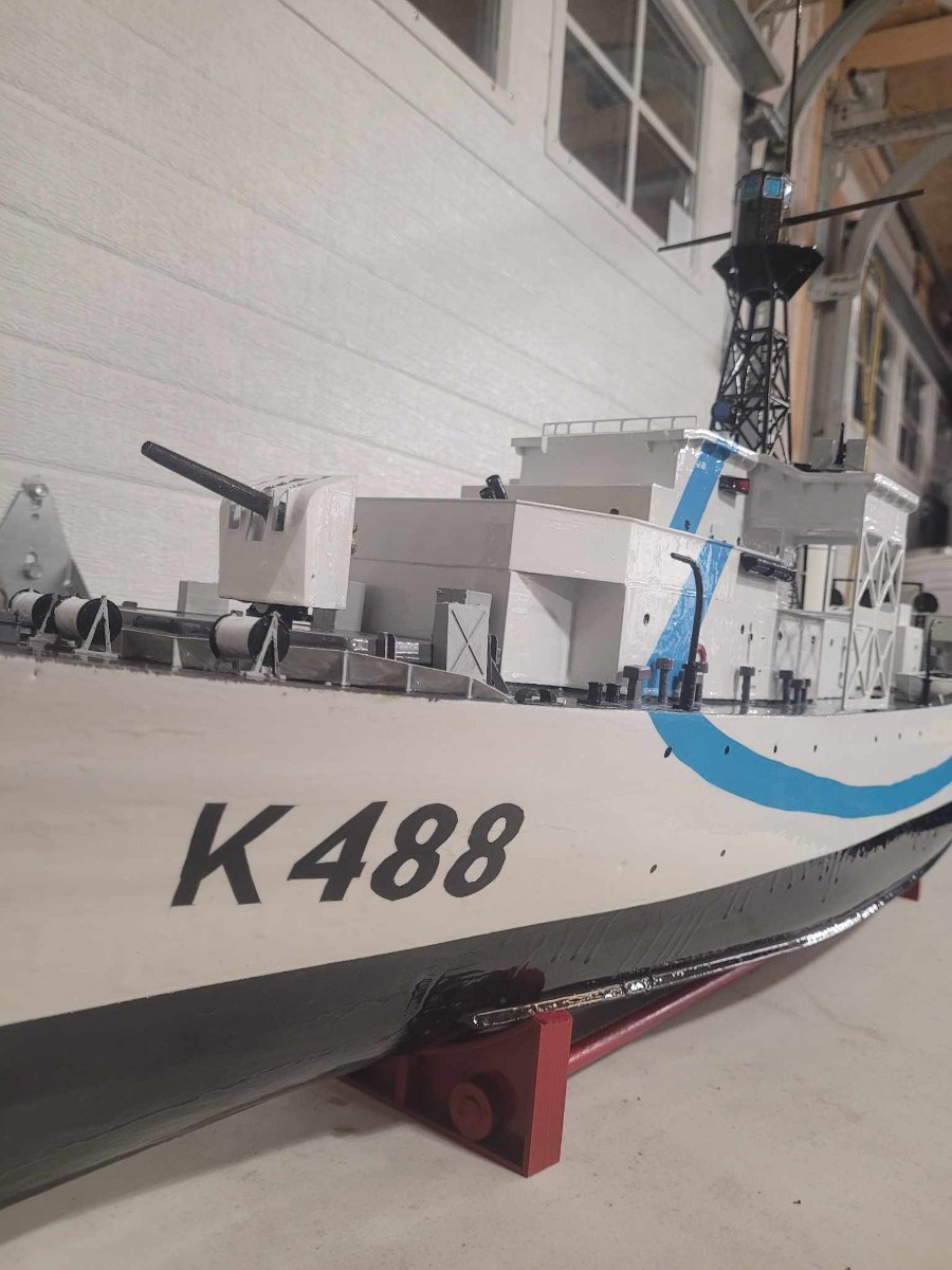
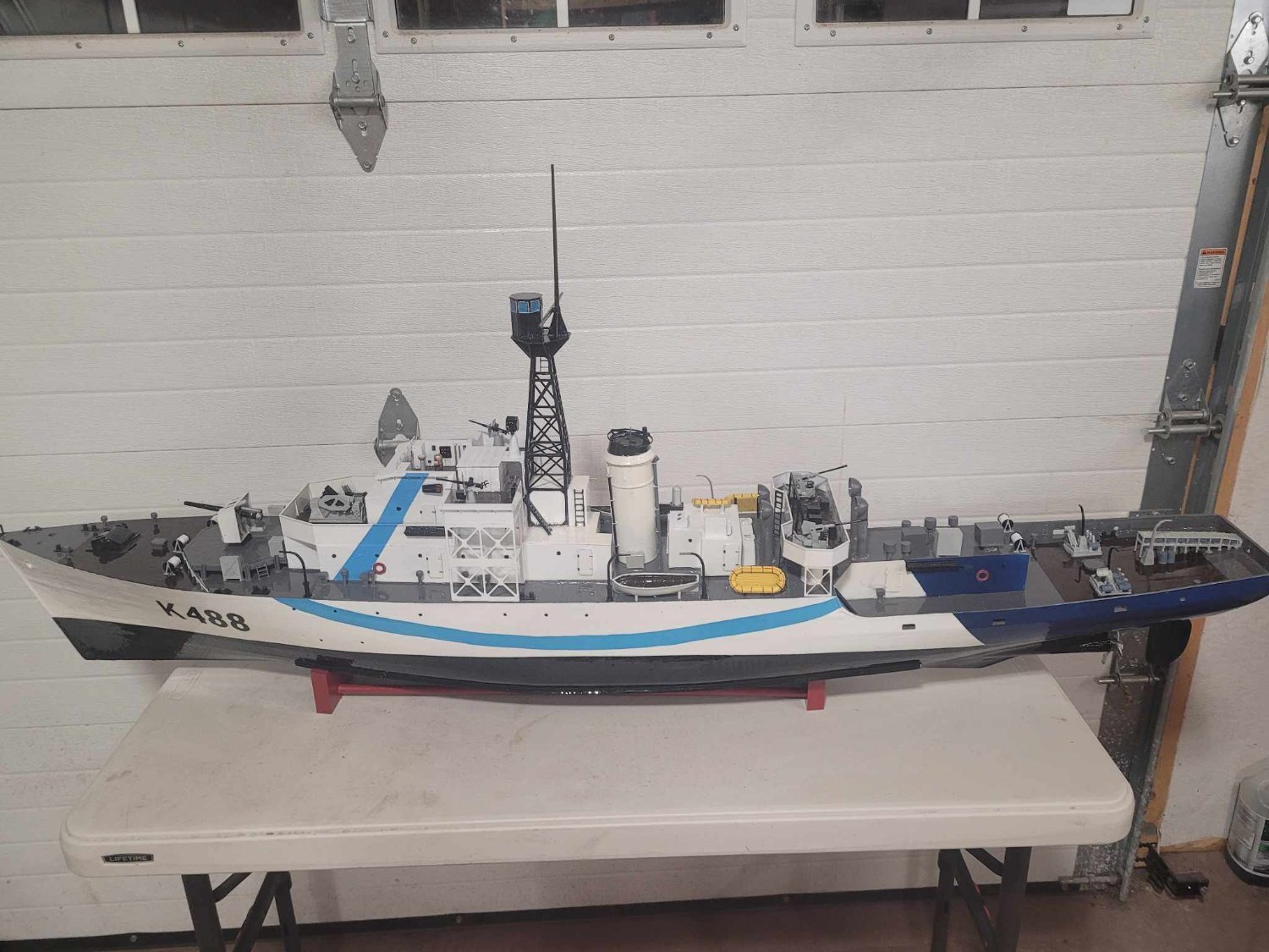
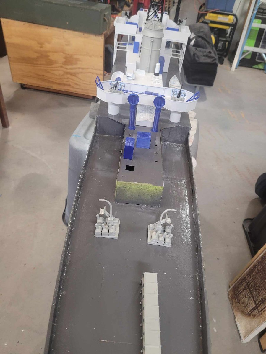
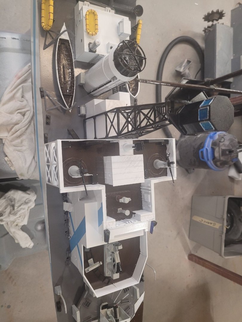
OK, here's how she looks after tonight. The bits on the table still have to get glued into place, then I need to add ballast, water test, then fill the remainder of the interior with foam so she's not likely to sink. I have to do up the K488 and paint that on still as well. I figure maybe a week or two of work?
-
OK....the spray on clear coat was a bad idea. Got a bit of bubbling. So. Another batch of West System epoxy got mixed up, and it's now curing on the superstructure... Please recall, this is destined to be a stand-off display model that first and foremost has to survive for several months in a pond.

-
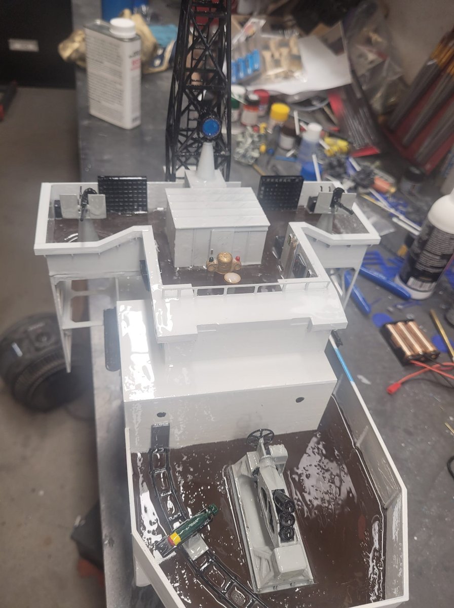
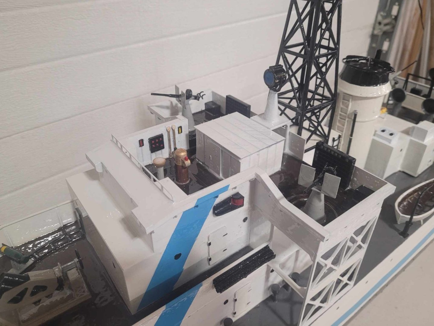
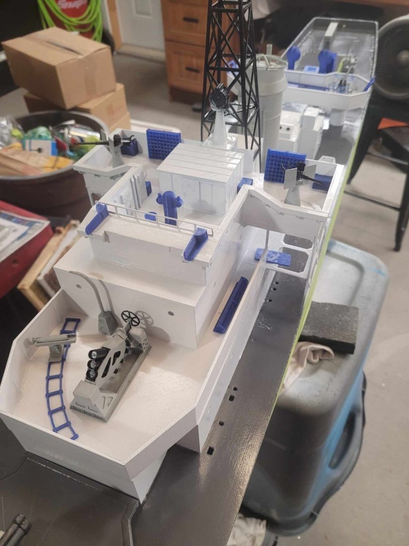
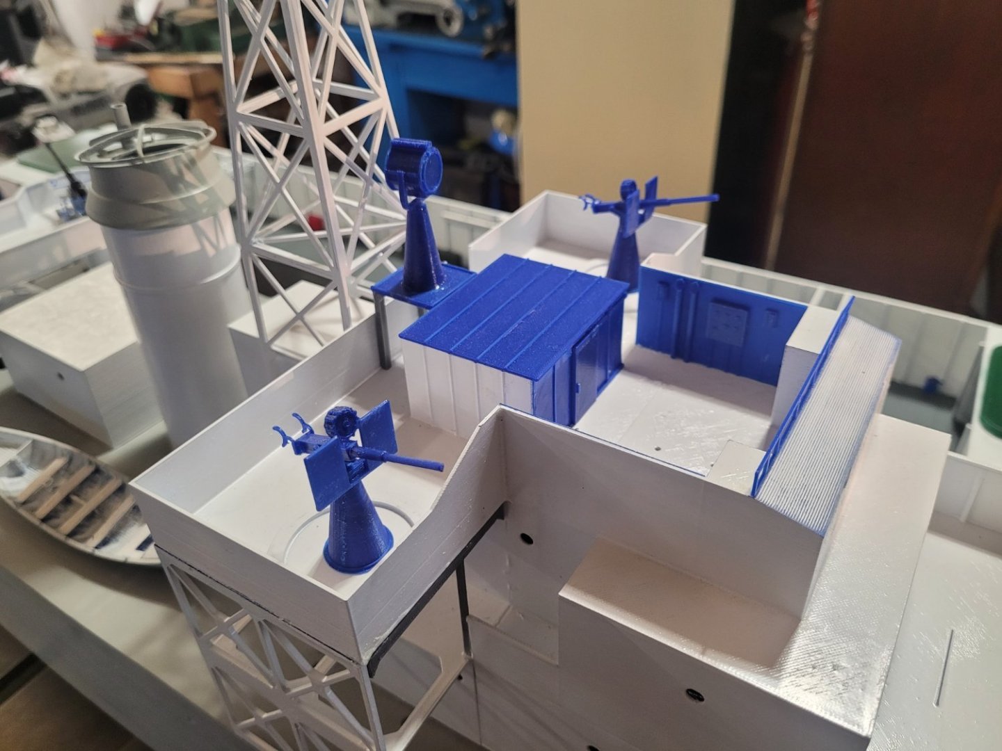
Whilst I wait amidst the humidity for the paint to fully cure, I have been plugging away at assembling the superstructure. The 'fiddly bits' got some attention last evening, with the forward superstructure seeing almost full completion. I glued on the mast, the 20mm guns, the searchlight platform, etc. Then I added some detail painting to the inside of the bridge area. The Pelorus stand got glued in, brass/gold finish with the appropriate red/green markers on each side for the compass correction balls. The phones were painted red and yellow, the indicators and 'buttons' on the panels were painted as well. Some touch-up white to cover a few little mistakes when I did the deck 'wood' faux finish. Gluing on the doors, painting the hinges and handles, adding the life-preserver rings, painting the port-holes...it was a good night. In looking at the superstructure, and comparing it to the hull, I have pondered adding a layer of the clear epoxy to it...but I think instead I'm going to put a few layers of clear gloss spray paint onto it instead. I'll do a test-shot of that tonight and see how it looks. With all the small nooks and crannies...I don't think the epoxy will do a good job coating things. 2-3 layers of clear gloss paint? That should suffice...I hope. Worst case? I have to re-print the superstructure in a year or two and re-paint things. Best case? It lasts. NS
-
Barncave Shipyard by mbp521 - Scale 1:1
NavyShooter replied to mbp521's topic in Non-ship/categorised builds
VERY nice layout. I see that there's still big Dillon press yet to be mounted there. I like how you did the formica work surfaces. My reloading bench is a 550 pound steel workbench with a 3/4" G1S sheet of ply that's been varnished on top with the whole thing bolted to the wall for sturdiness. -
Masked...and sprayed. Now to dry it for a few days, then another layer of clear epoxy coat.

-
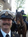
I never found out his plane's actual markings - I never saw his logbook before he passed. Alas. That said, I did send him a completed 1/48 Tamiya model of the Beaufighter while he was still with us. NS
-
My Great Uncle Harold flew with 404 in WW2. He was a Beaufighter pilot.
-
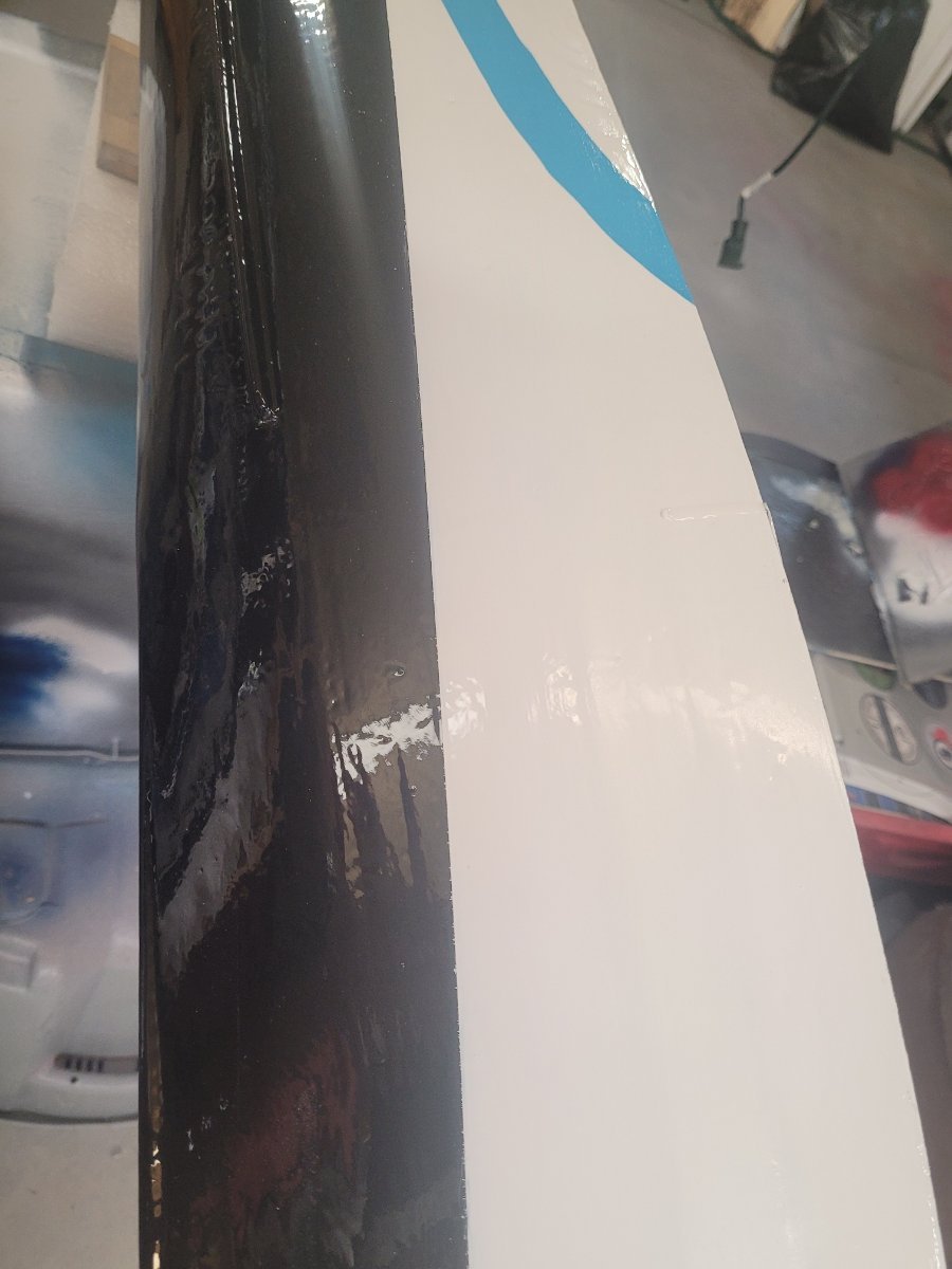
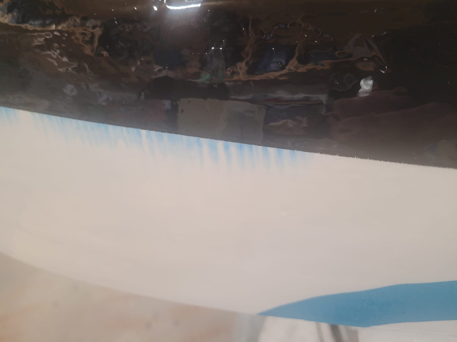
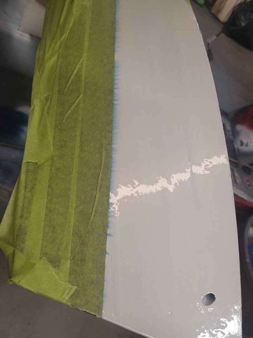
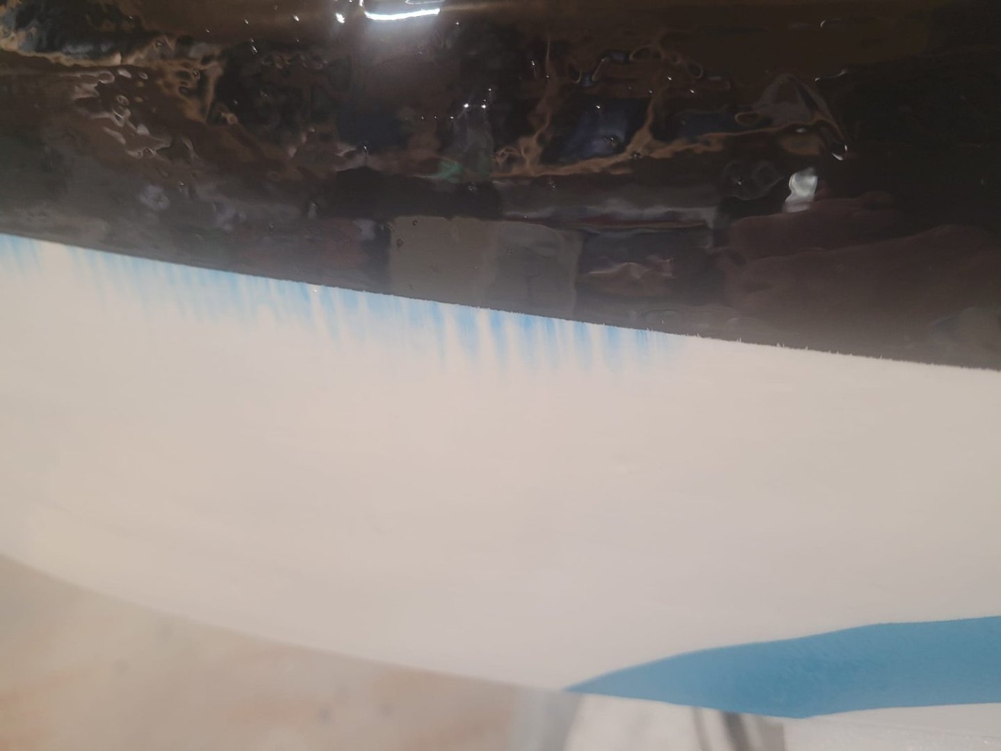
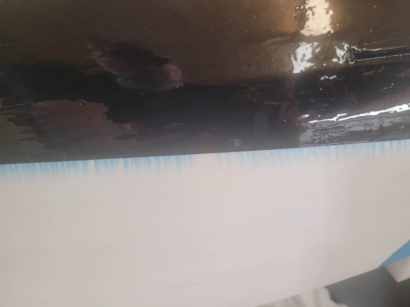
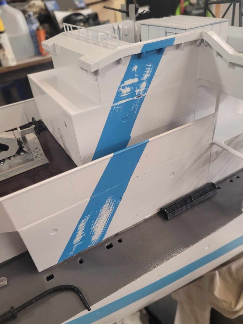
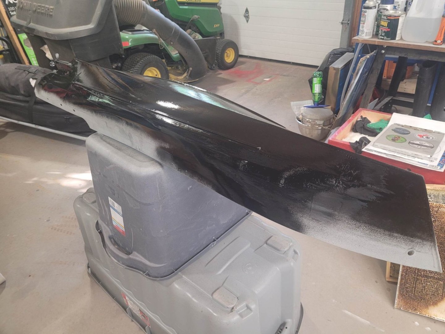
OK. A mistake I made a few steps ago has come back to bite me now. As you can see, there's some bleeding going on...I put on a layer of West System epoxy to give the hull a really good seal coat...and the blue marker that I used to mark the waterline has bit me again. The marker reacted with the epoxy and bled blue. Damn. All I can see to do is to let it dry, then put on a touch-up layer of white, then do another sealing layer of epoxy. Dang.
-
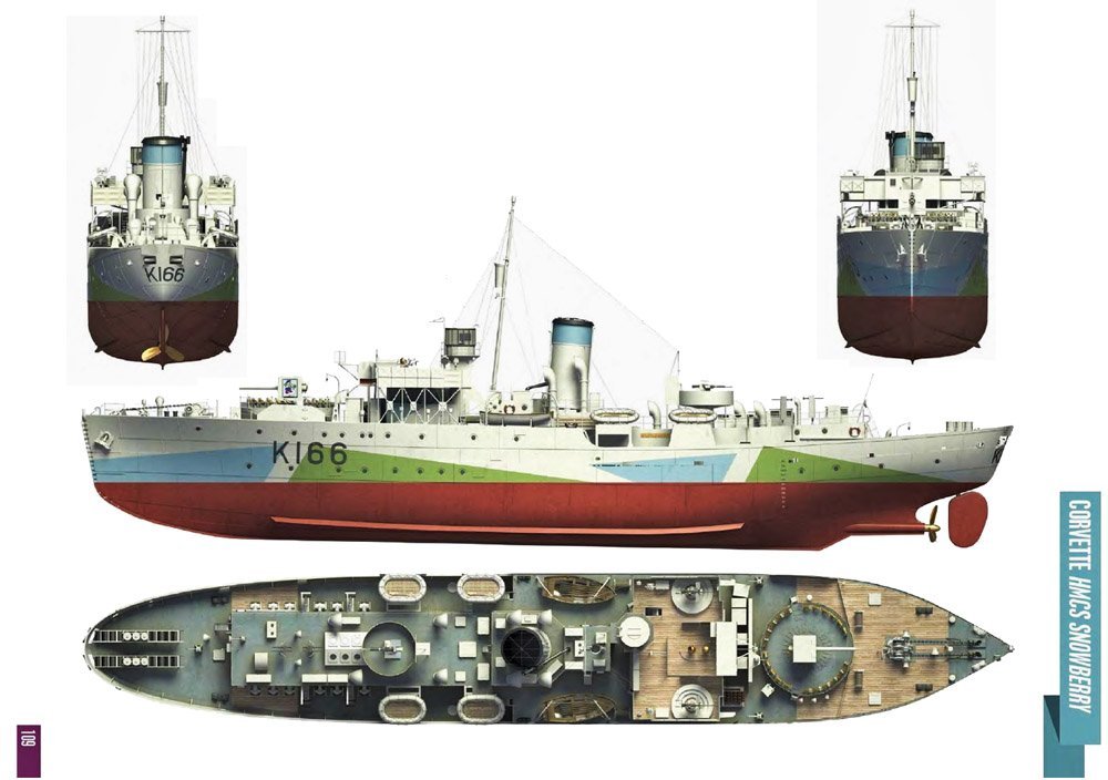
David, I'll reference this website: 1/72 scale wood deck for Flower Class | Ships of Scale And this image. There were sections of decking on the Flower class that were wood. I am assuming that the same was true for the Castle class. I'm OK with being wrong...but suspect pretty strongly that I'm correct that they had wooden deck areas, (OK, wood covering steel decking...whatever...)
-
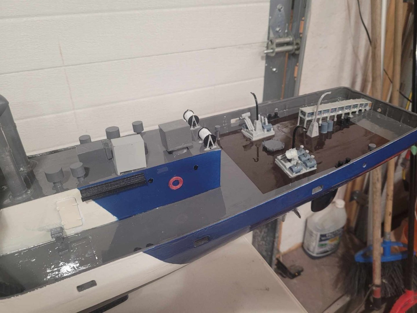
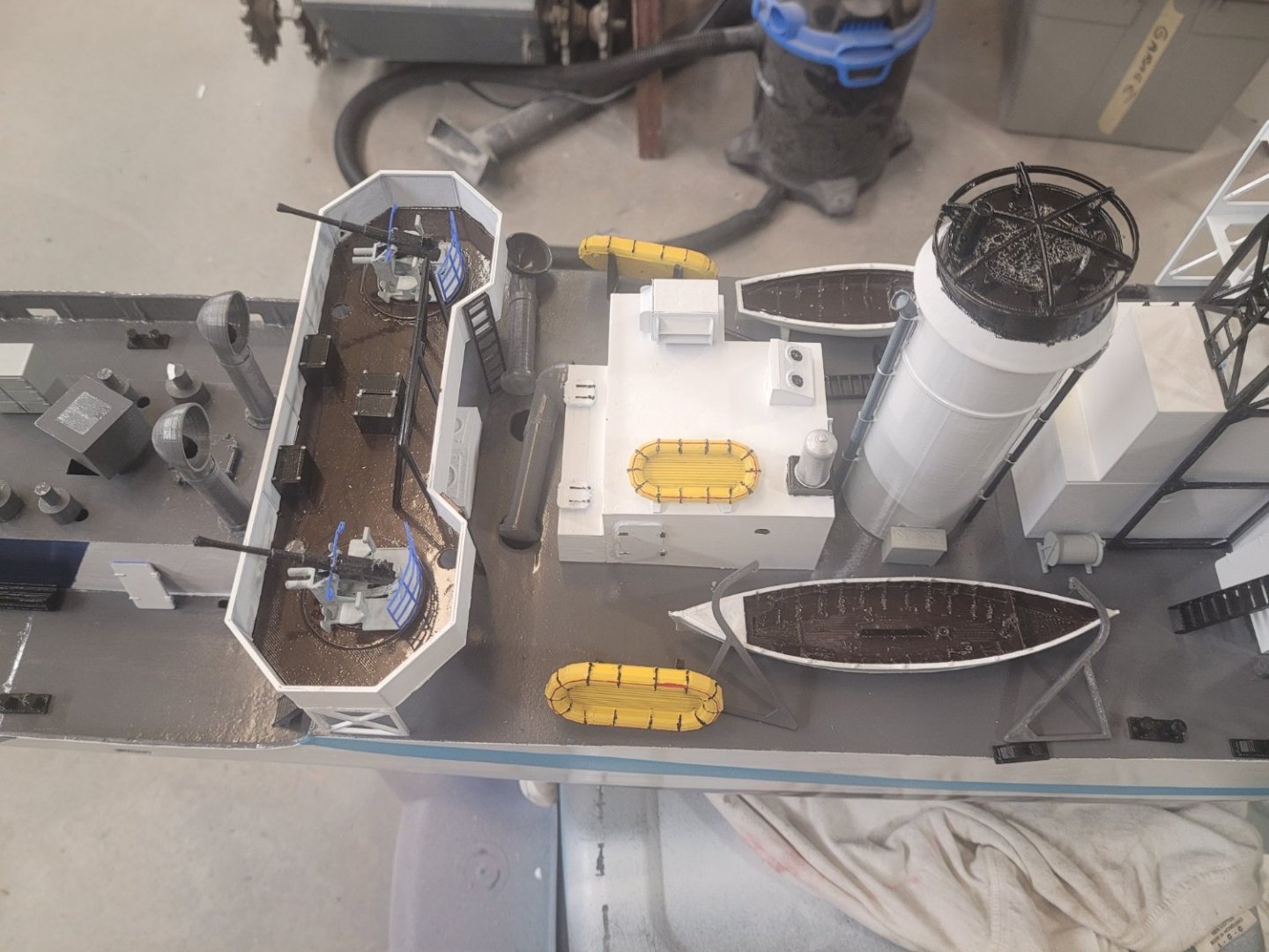
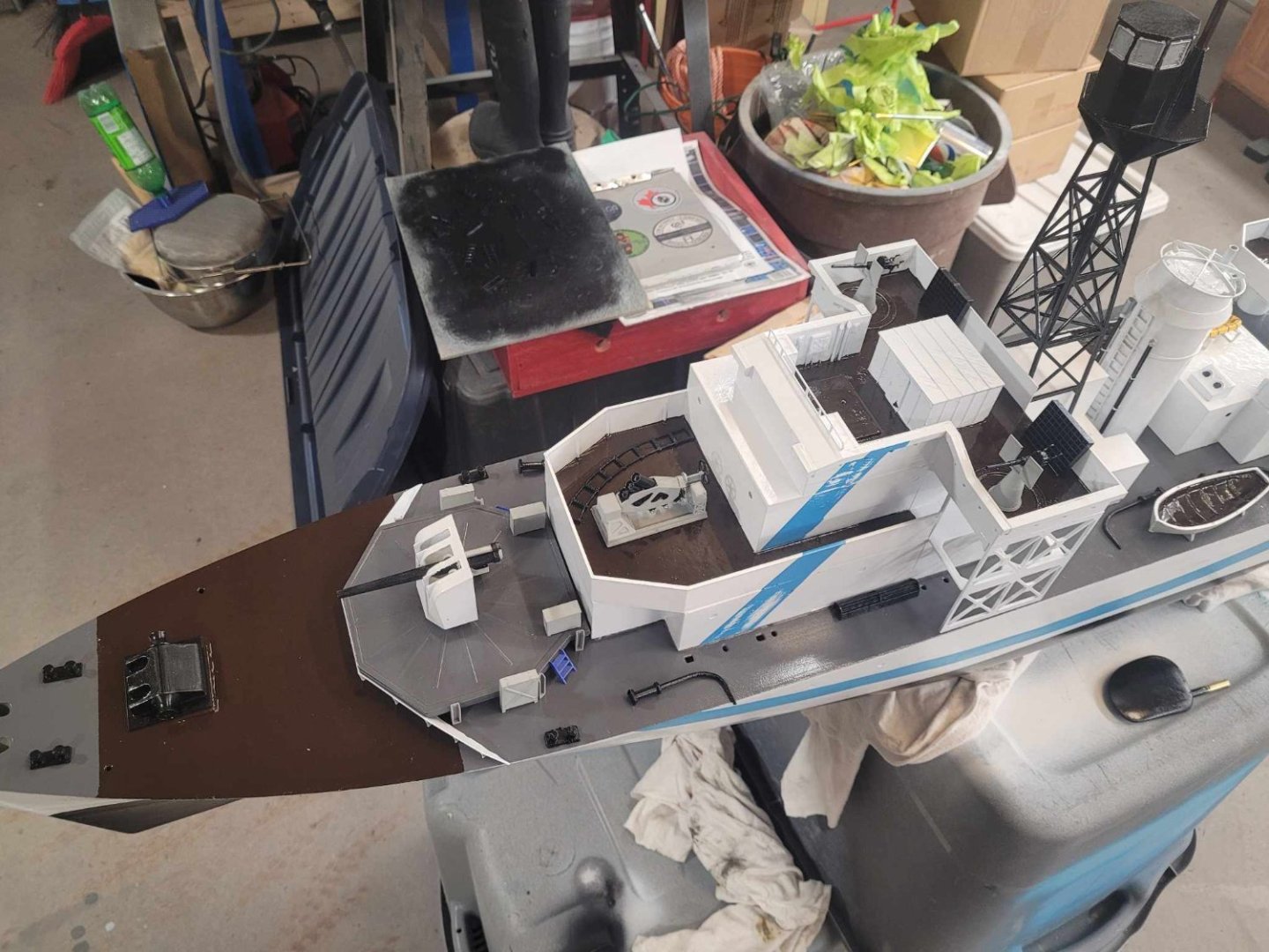
I went over the ship last night, and put all the bits and pieces in place. I think I have all the parts printed. Most of the parts are painted. Some of the parts are glued in place. The next step will be finishing the painting of the 'bits' and gluing any of them in place on the superstructures that I can. After that, I plan to put on a layer of West System Epoxy over the painted hull - as a protective and sealing layer. The last paint went onto the hull over 2 weeks ago, so it should be fairly well dry by now. Because the model is destined to be in a pond for several months, floating on display, I need to be certain that she won't leak. My plan for retaining the superstructure is to mount a threaded rod on a block that I'm going to affix to the keel on the inside, and have a hole protruding through the top of the superstructure. I'll then be able to tighten it down with a nylock nut to hold it in place. The inside of the hull will get the rest of the ballast added to bring her closer to a correct depth, then the voids will be filled with foam, so that if there is a leak, it will NOT see the ship end up on the bottom of the pond.
-
Navy guy excited to be here 🏴☠️
NavyShooter replied to GRATEFUL LITTLE PHISH's topic in New member Introductions
Welcome aboard! -
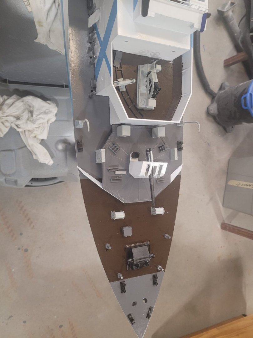
Plugging away...some decent progress. Realized that I've not printed all of the bits - there are a lot of the ventilation mushrooms to be made! I painted some sections of the decks in brown to represent the wooden portion of the decks. My never ending problem with bubbling paint seems to have returned as well. I'm going to end up with some extra work due to that. I expect I'll have her done in the next few weeks.


-
Barncave Shipyard by mbp521 - Scale 1:1
NavyShooter replied to mbp521's topic in Non-ship/categorised builds
That's coming along beautifully! Well done! -
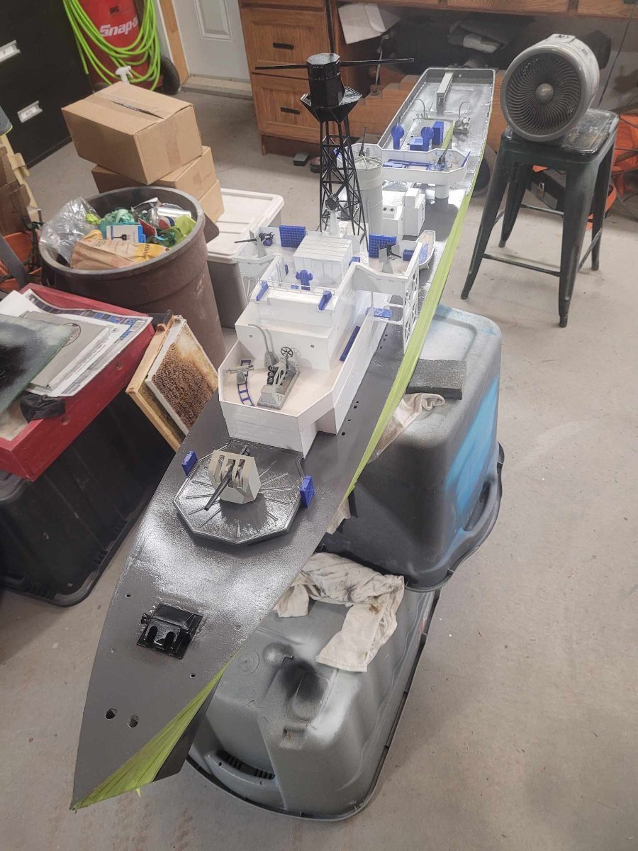
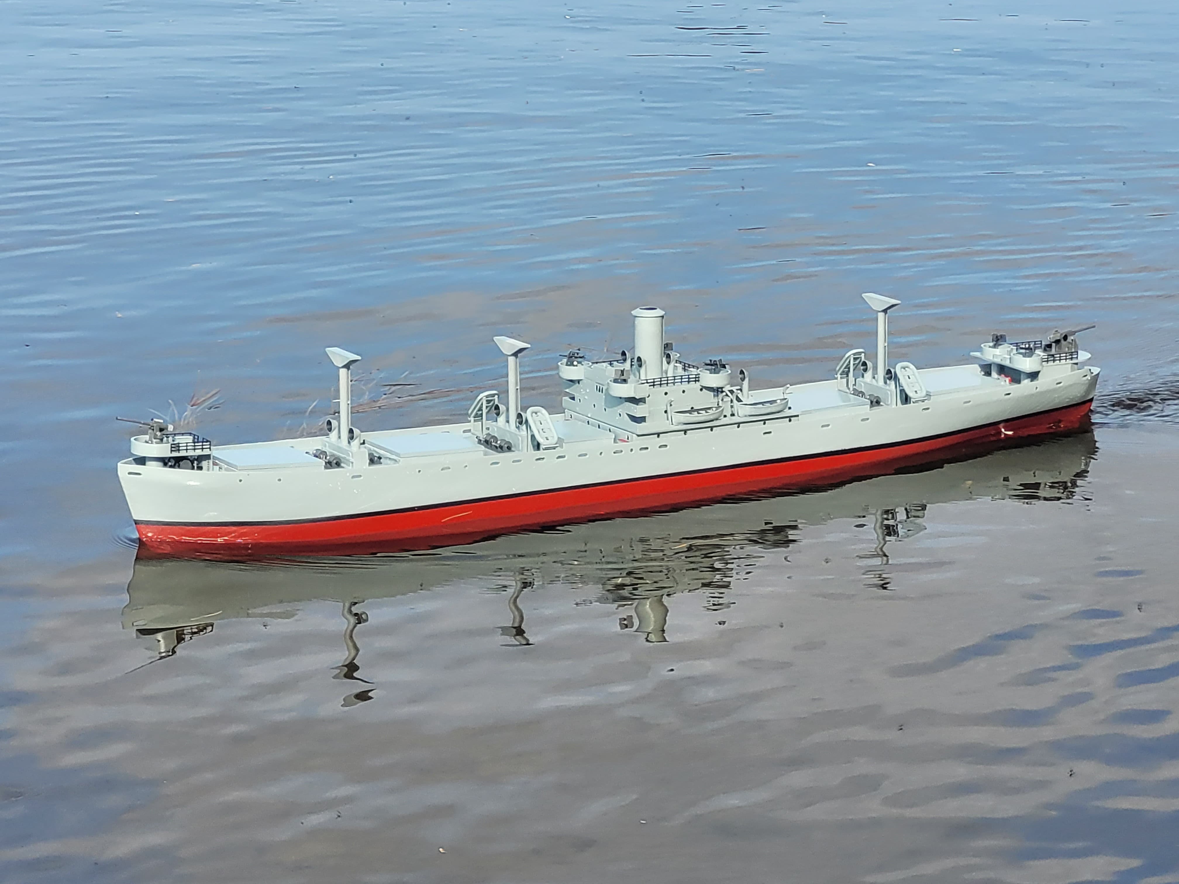
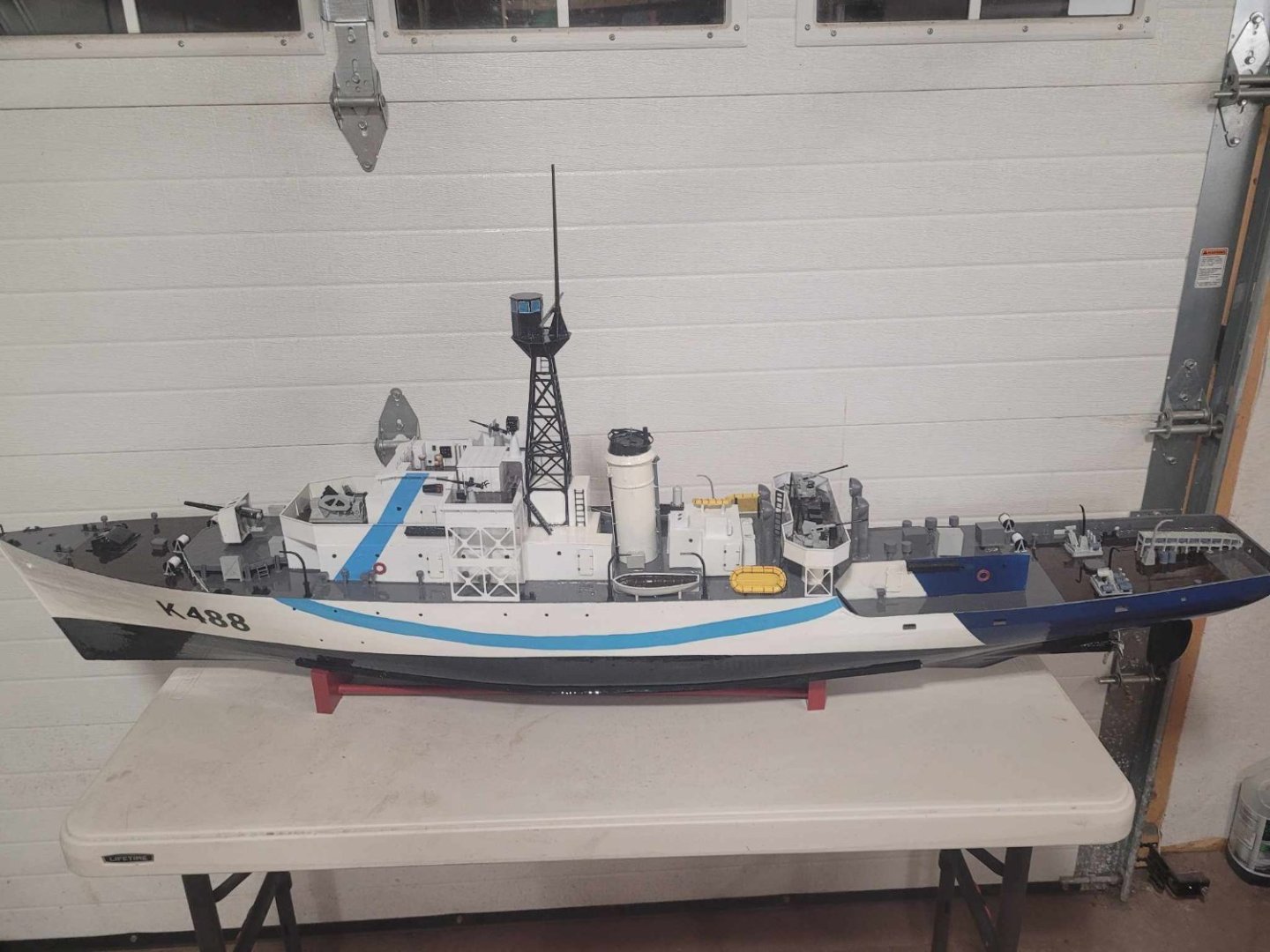
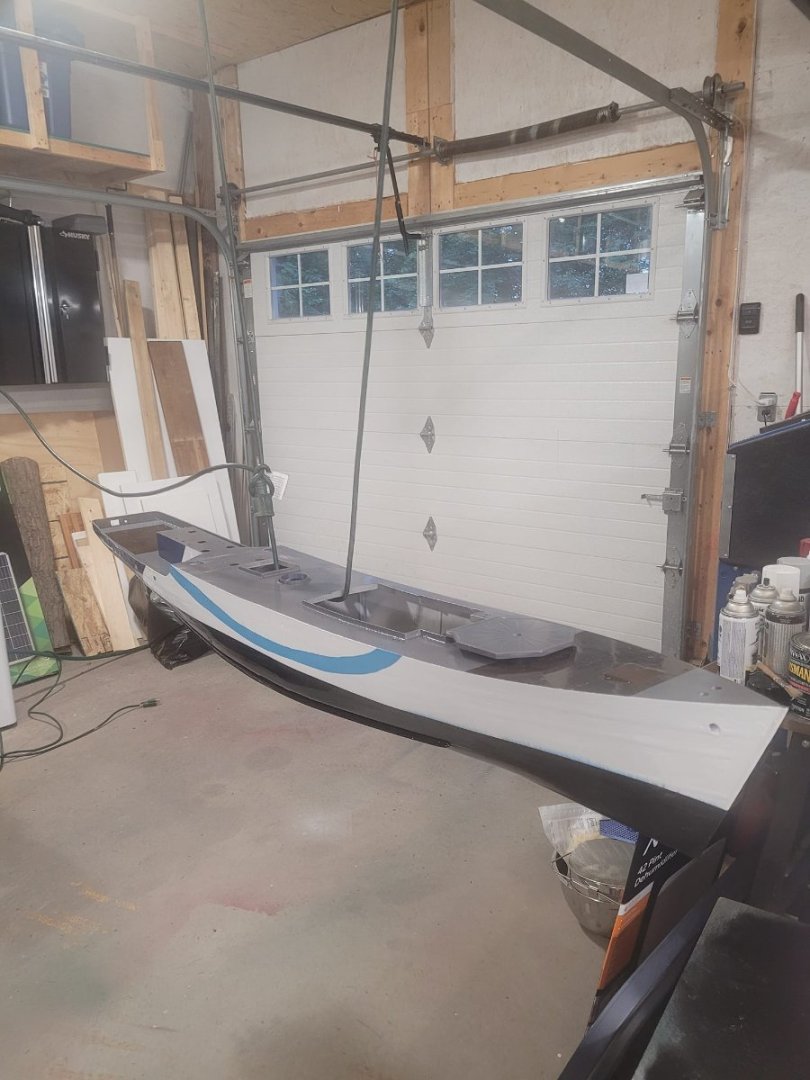
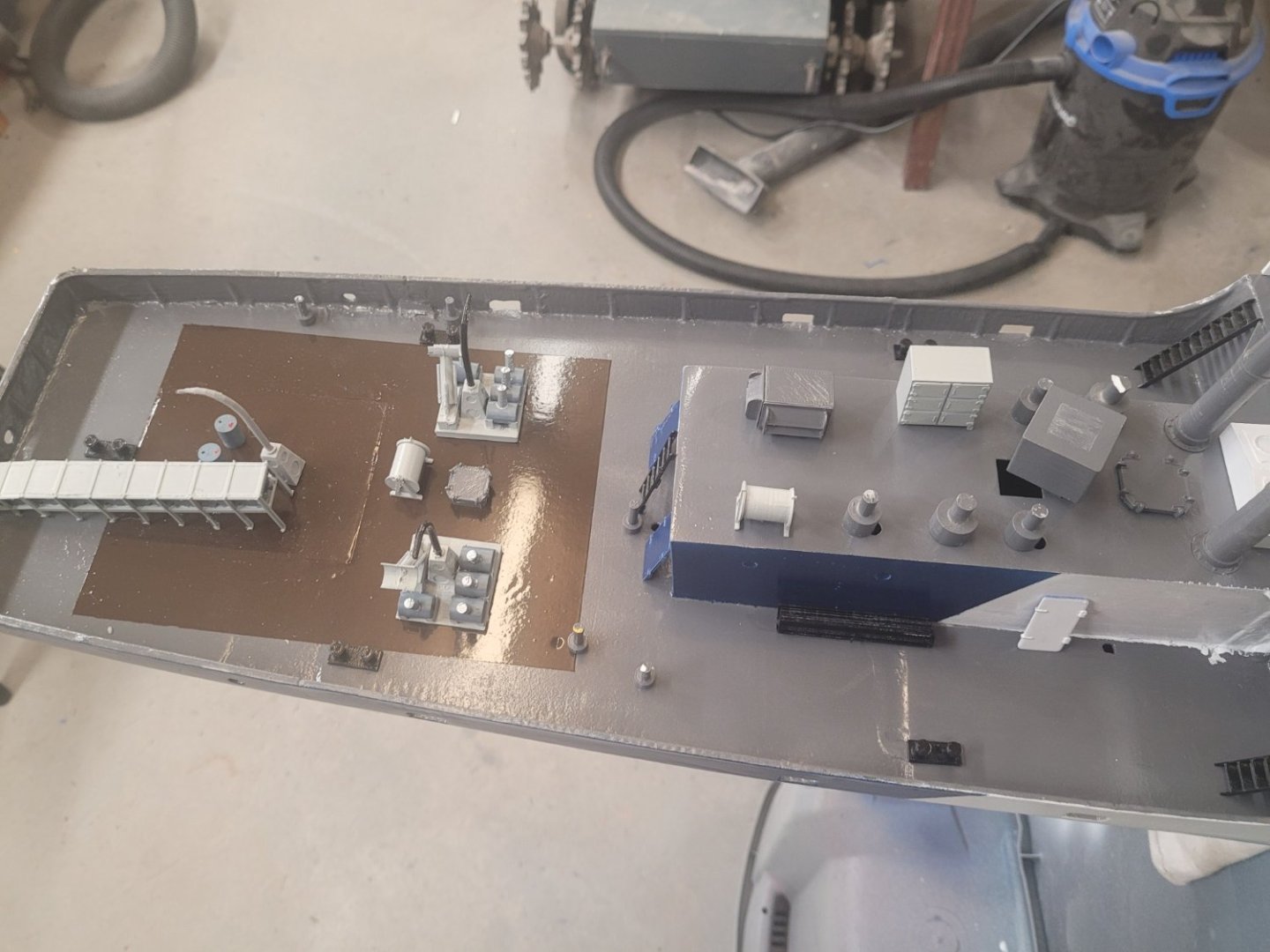
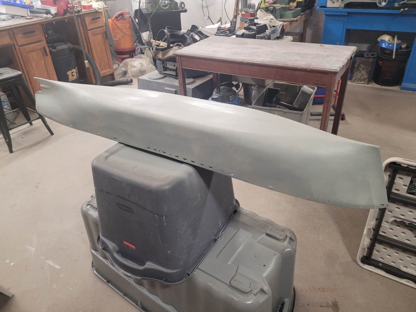
She's come a fair ways in the past couple of weeks. Even with me being out of area for a long weekend. You can see the camo pattern I've adopted. Black hull, white sides, light blue 'swoop' and dark blue stern. Decks will be a standard dark gray, and in doing a bit more research, I've determined that there were portions of the uppers that were actually covered in wood, so I'll be digging up some grown paint and adding that in too.


-
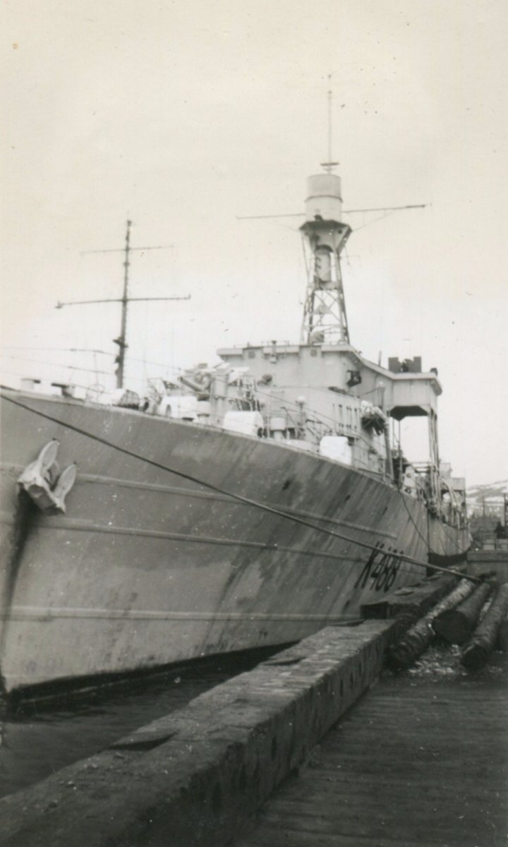
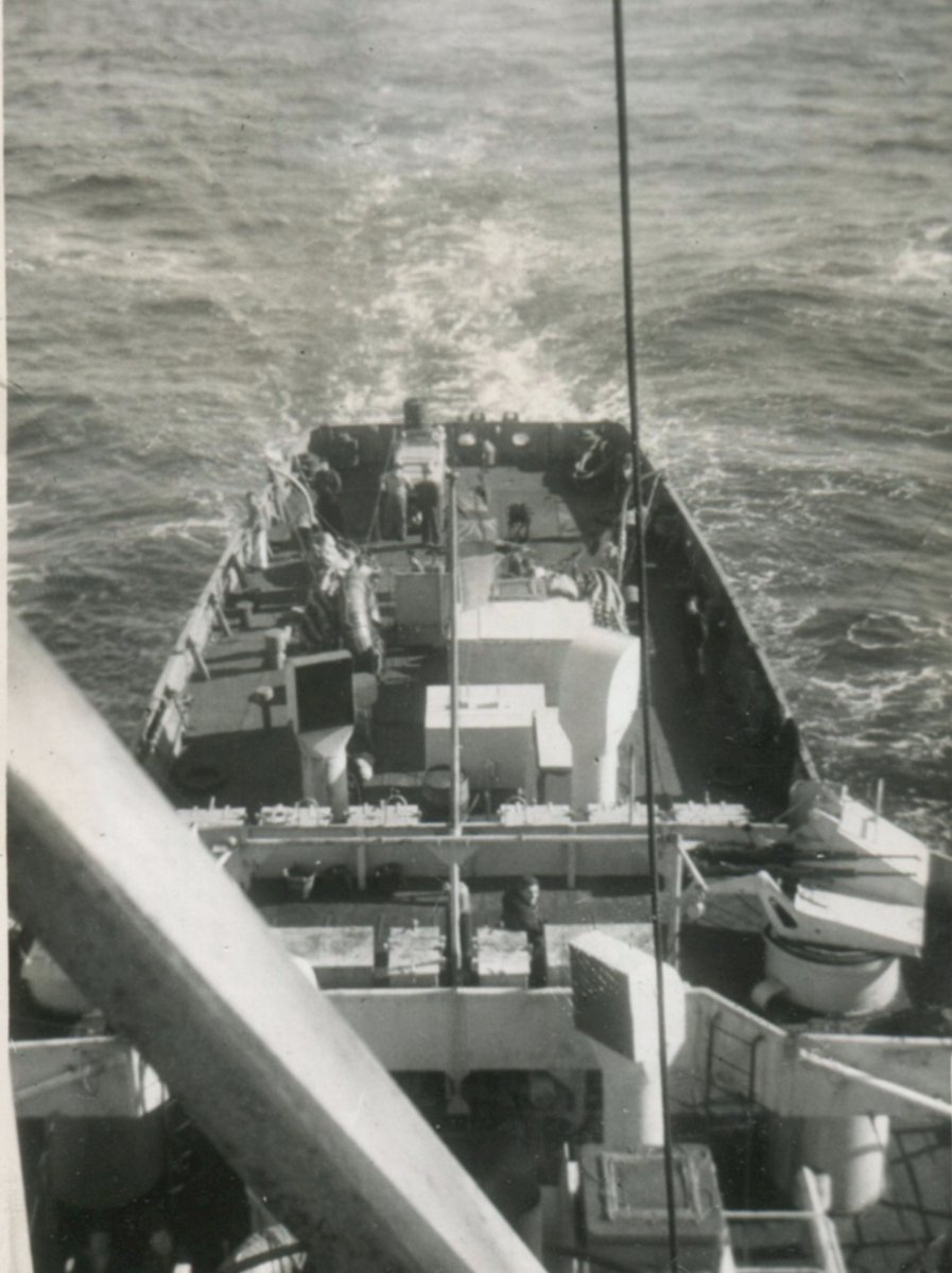
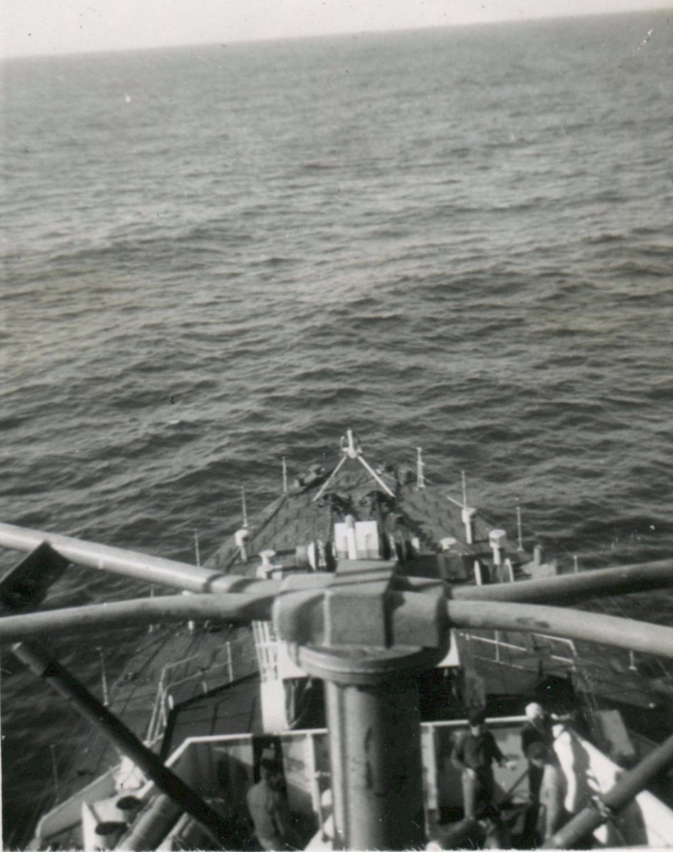
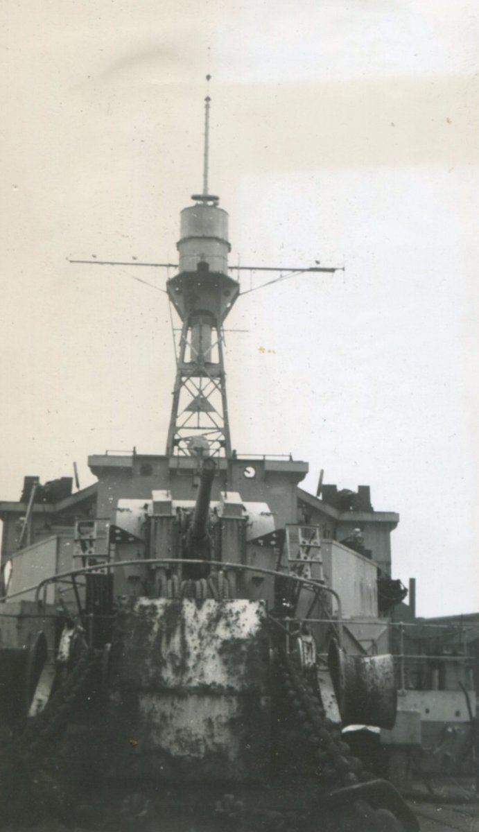
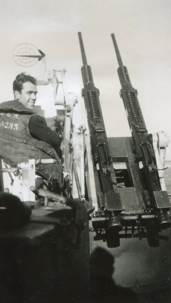
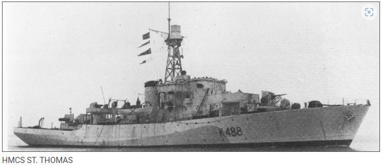
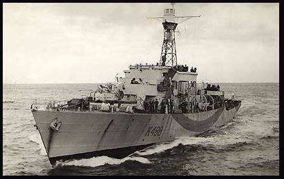
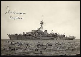
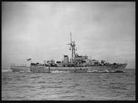
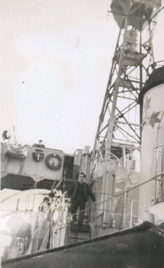
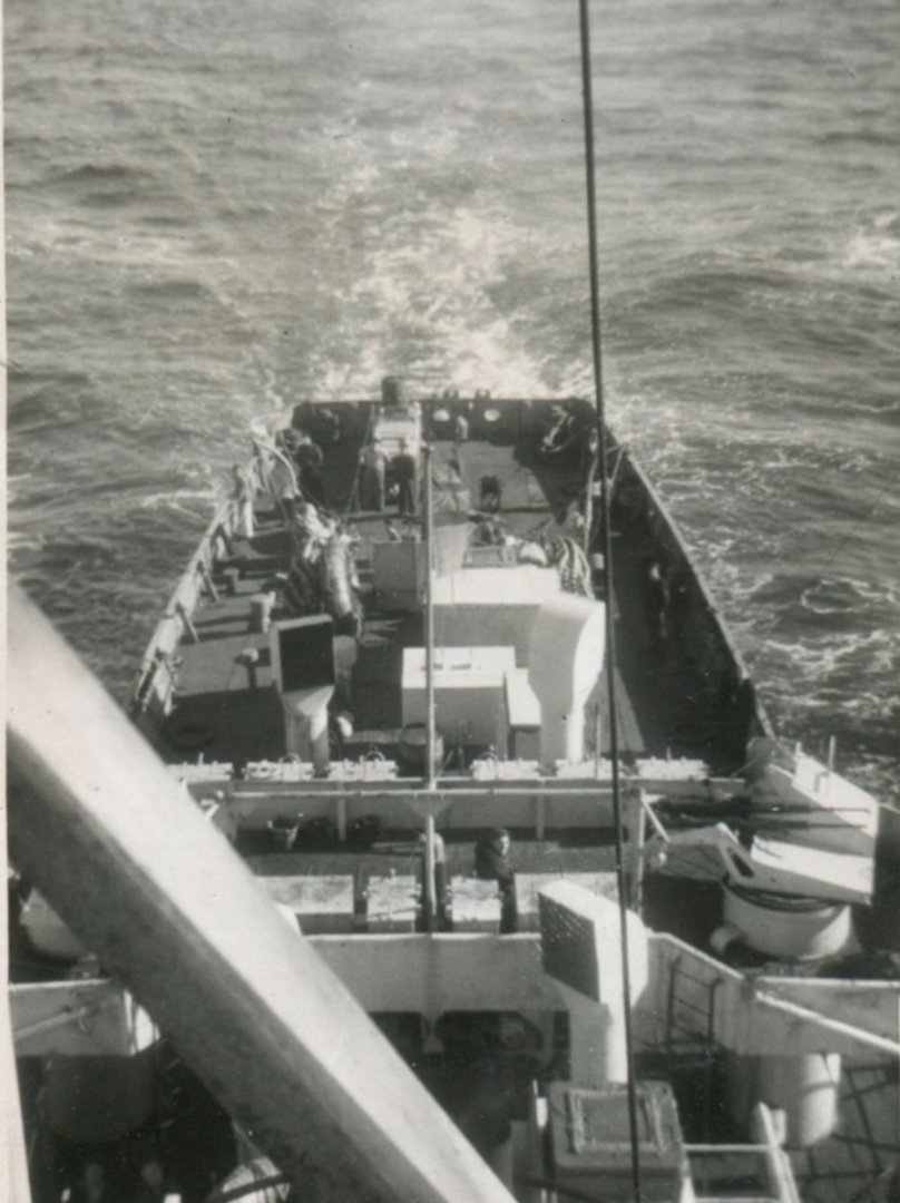
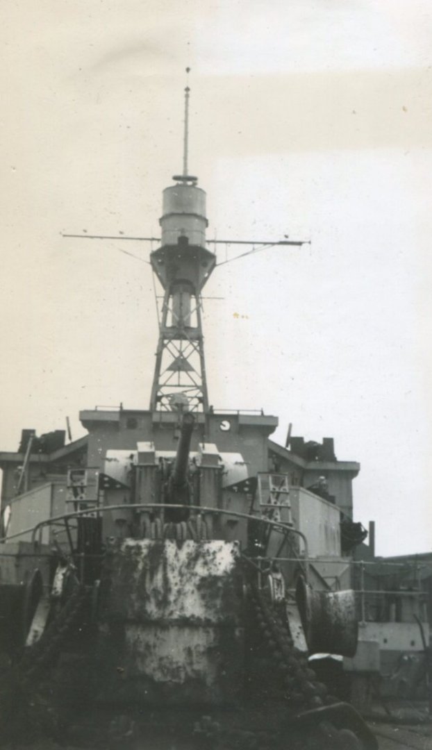
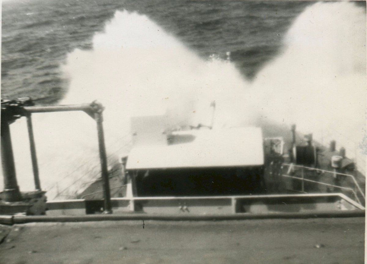
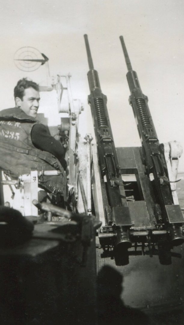
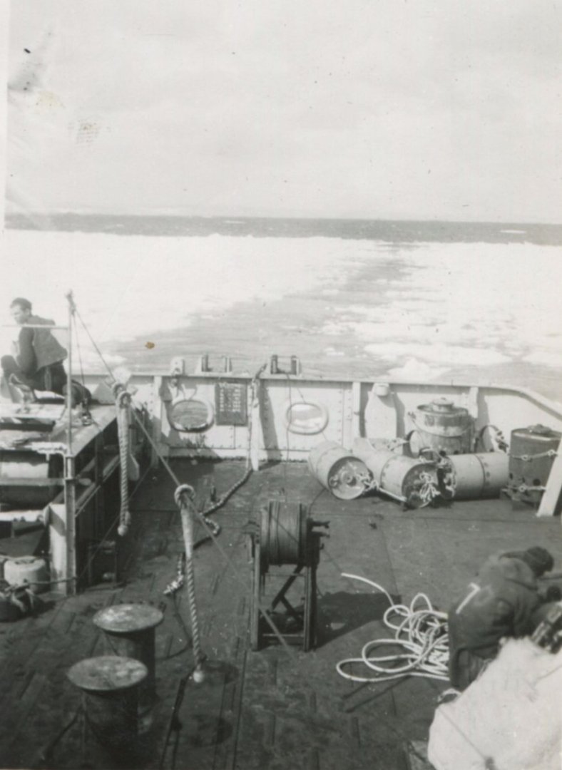
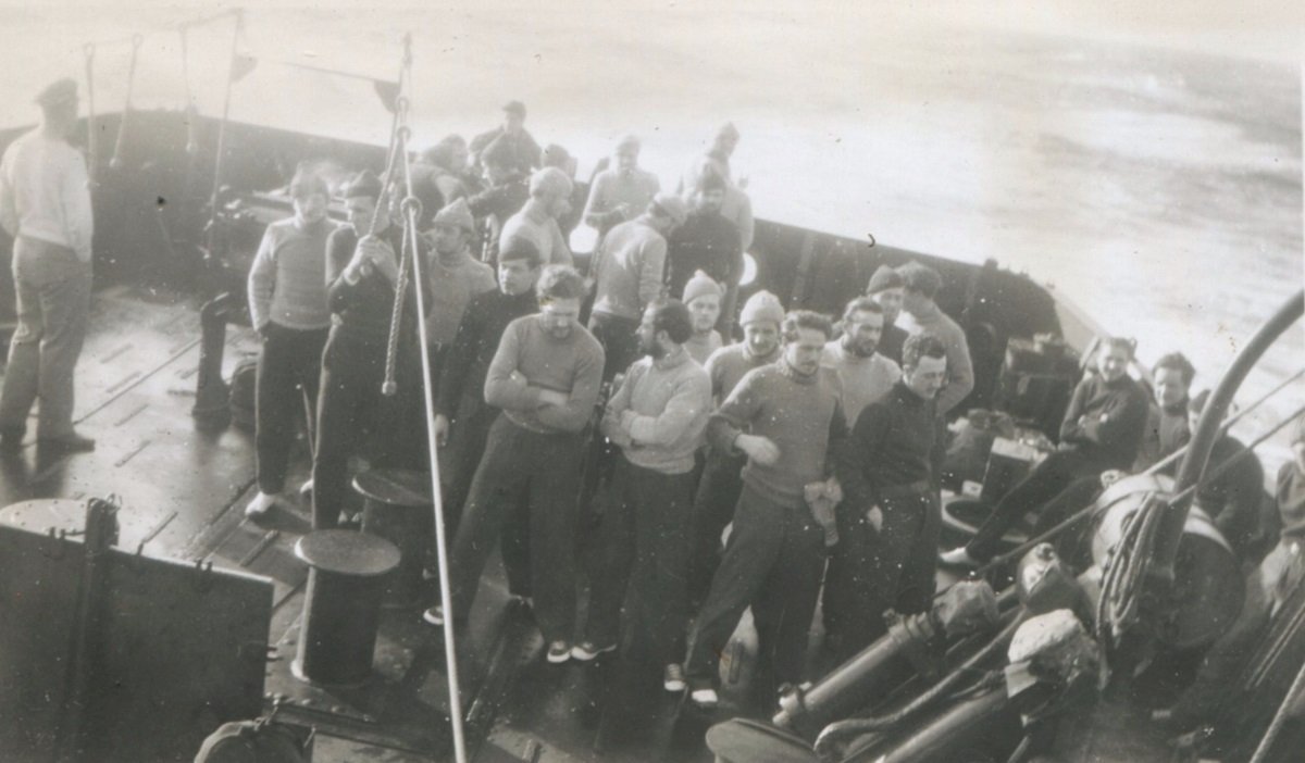
Here are the photos I've managed to collect of HMCS St Thomas. From what I can tell, there are 3 different camouflages that may have been applied to her. Looking at Pic 1, you can see a light hull background, with a darker swell or wave coming up. Pictures 2 and 3 show the light hull with a darker slash and very dark stern. This is repeated in Picture 4 and 6. Picture 5 shows a simulation of a smaller hull in a darker colour against a light background hull. My intent is to 'match the swoop' as seen in pictures 2 and 3, with a darker stern area. My interpretation of these photos is that it's a white hull, with a blue 'swoop', and a darker blue or dark gray stern. I've carefully selected paints (the best that Tremclad sells!) that I'm going to use to do the painting. First layer will be the white base layer. Then I'll add a light blue swoop with the slash that goes across the superstructure, then a darker gray stern. Sackville is white with a very light blue. That's the source of my inspiration. Anyone have any better images or colour recommendations? NS


-
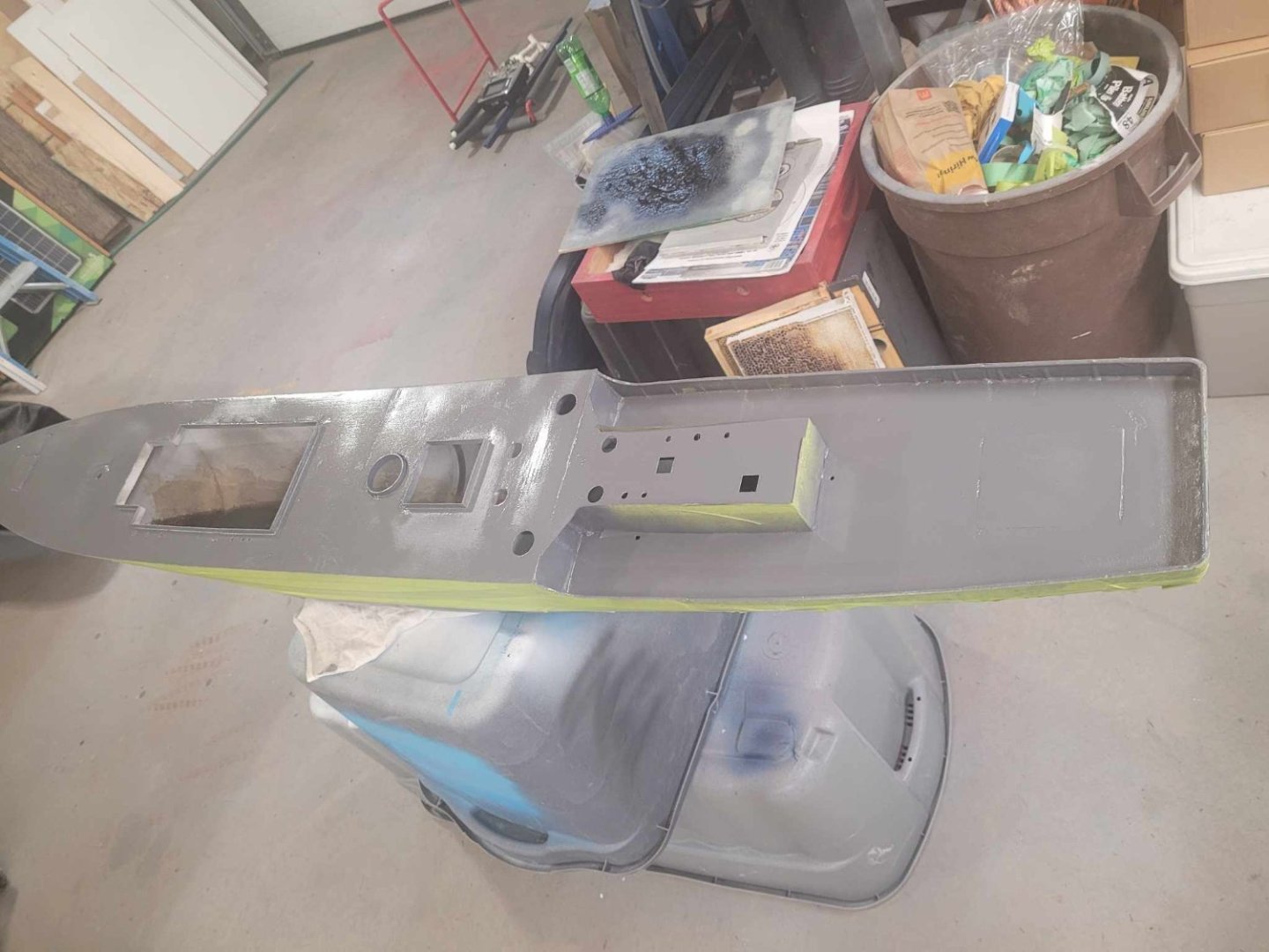
The progress this weekend was....a second coat. After waiting over 48 hours with a small heater/fan pointed at the hull to dry things out faster. Tomorrow, I'll be putting her into her cradle and marking a waterline, then it's off to the 'above the waterline' work. I did a screen capture of a video from a gent who built one, and he's got her with a red hull (incorrect) a black boot top (irrelevant with a black hull bottom) and a dark gray upper hull, with some black camo lines on her. I'm leaning towards a white camo style, with dark blue lines. I suspect we're working from similar ship photos, but his interpretation of the colour might be off because it's black and white. I'm not going to say he's wrong...but based on my proximity to HMCS Sackville, I'm going to guess that other Corvettes were painted up in similar colours to her. NS
-
Have a look at the "Night Shift" channel on Youtube. ( @nightShiftScaleModels) He built a diorama of a MkIV in a trench/crater that shows some really good detail and weathering techniques.
-
There was mention early in this thread of there being a 'second ship' - the second Liberty Ship that I printed at the same time as I did mine - that being for my buddy the model railroader. Well, last month, he brought the hull over and I helped him learn about gelcoat and fiberglass. He stayed for the first layer - I did the next few on my own, and last night I called him over to help shoot the first layer of primer. There's a couple of minor spots that I've sanded again and added a bit of red body putty to those. A bit more sanding and another layer of primer, and she'll be good to go. He's going to bring her home to finish up the rest of the build. NS

- 54 replies
-
- 6
-

-
- Liberty Ship
- Finished
- (and 2 more)
-
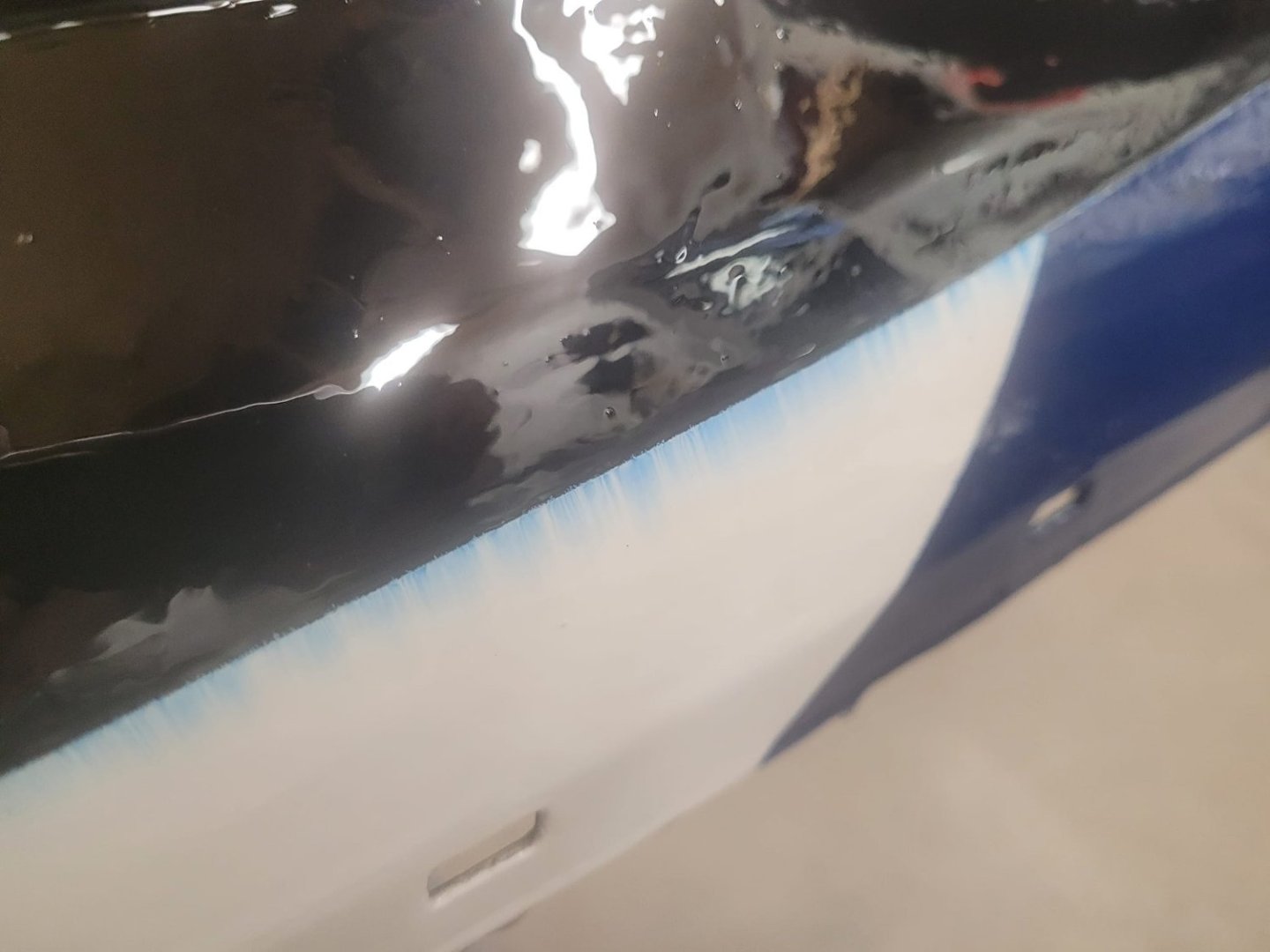
A friend of mine pointed out that these ships in RCN service actually had BLACK painted hulls below the waterline. So. With a pause enforced by being out of province for a bit for work, I'm now back to the bench and decided to shoot a layer of black gloss on the bottom of the keel. More to follow...and this time I'm going to be PATIENT and WAIT the 48 hours before recoating. I promise.
-
Maybe I screwed up, but maybe not. From what I can see, there's 20mm Oerlikons that feed from both left and right.
-
Archaeological Evidence for the Development of RN Gunnery
NavyShooter replied to Steve20's topic in Nautical/Naval History
OK, Having sailed in the Navy for a lot of years, I'll observe a couple of things - Firstly - everything has a place, and it should be in place. Secondly, on a Navy Ship, most of those 'places' were designed to properly hold those things, and keep them in place. A big factor in objects on a ship is inertia - but I'm certain you all know that. A cannon, on wheels, even when secured in place will still have some range of motion - the flex or stretch in the lines will enable this. The weight of a cannon and its carriage is huge - the 3 pdr I have in my garage takes an engine hoist to move safely into and out of the bed of my truck. Cannon balls are round, but they are not on wheels, nor are they loose rolling about on the deck. In looking at pictures online of HMS Victory and other ships, there are cannon ball holders either behind the guns on the deck, or on the bulkhead beside the guns. Those holders see at least 1/3 of the ball sitting into the wood, with only maybe 2/3 of the ball exposed. The deck ones, in heavy seas, would not require a lot of effort to toss a blanket on top of them to ensure they wouldn't roll anywhere. The bulkhead ones? I suspect that if you looked closely at them, you'd find wear spots where they'd have a cover tied on to help keep them in place. Before a ship was to sail in the modern Navy, we'd always do "secure for sea" rounds on the day before sailing. Are things tied down, are they secure, did they use rope instead of a bungee cord (NEVER use bungee cord!) I suspect that the same applied for the age of sail. When a ship is alongside and open for tours, you don't see the chains holding the helicopter in place in the hangar. They're all disconnected and hung up along the bulkhead, and are practically invisible to a visitor. They're looking at the fancy helicopter, not the chains and clips and such. If you asked a visitor to a ship how a helicopter was secured, they'd probably not have a clue. You'd need to be a member of the Air Det to know which chains go where, which tie down points to use, which shackle point on the helo is appropriate for use and so on. -
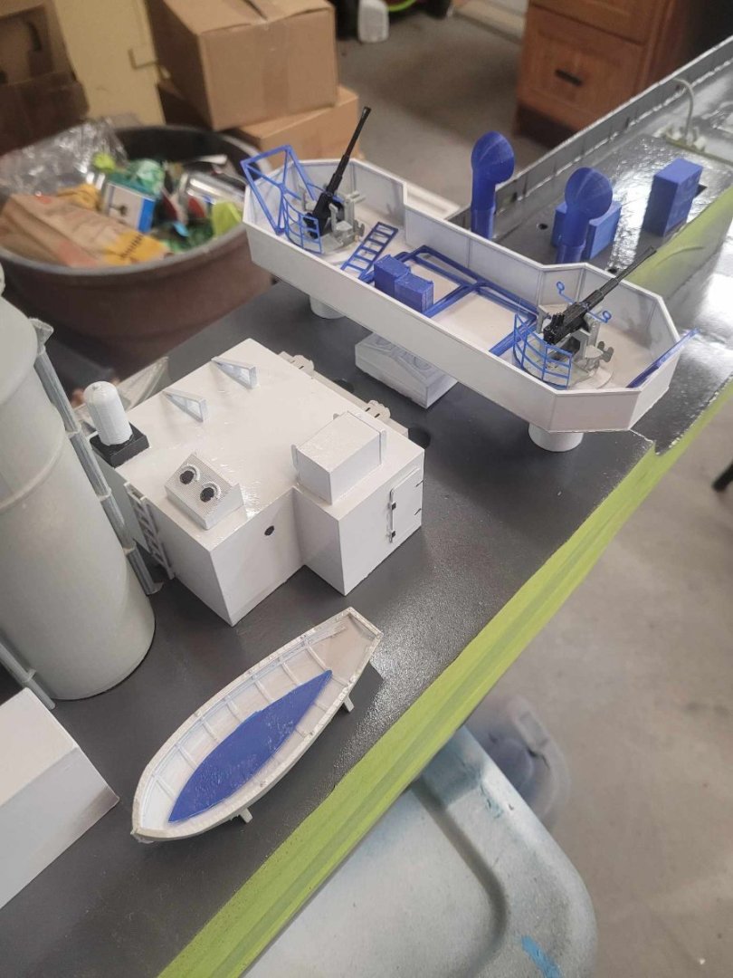
Some slow progress - I spent the weekend working on a hull for another friend of mine. He's a model railroader, so ships are not his thing. He brought beer over and we puttered away in the garage building a rudder, and getting a layer of gelcoat over his hull. I did assemble the Orelikon guns and the searchlight platform though. Starting to come together. NS
-
Barncave Shipyard by mbp521 - Scale 1:1
NavyShooter replied to mbp521's topic in Non-ship/categorised builds
I love my Chargemaster! Great work, and I look forward to your continued updates! -
Barncave Shipyard by mbp521 - Scale 1:1
NavyShooter replied to mbp521's topic in Non-ship/categorised builds
Very nice design. I wish to see more details of your reloading bench though...I have a modular design for mine, with a metal bench, and a wooden work surface (no sparky!) and I have my presses setup on 3/4" ply bases that have a standard bolt pattern so I can swap my Dillon 550 and my RCBS out whenever I need to go from speed of production to precision of production. 🙂 I know you've mentioned HVAC, but I'll highly suggest adding a spot for a dehumidifier as well. Humidity is a killer - both for wooden models (if that's your preference) but also for powders. When building your powder storage box, I recommend a fully wood construction, with brass fittings (again, no sparky!) (Said by the guy who used to instruct the reloading course at the local club) NS