


Jaager
-
Posts
3,084 -
Joined
-
Last visited
Content Type
Profiles
Forums
Gallery
Events
Everything posted by Jaager
-
I wonder if there is much difference between Stockholm tar and Pine tar from Carolina or Georgia? There may have been localities with petroleum seeps that used it, but up until Drake's well in 1859 the sap from conifers would have been the waterproofing material? It is not 000 000 000 black. On sail reinforcement ropes? It would have them last longer, but canvas is much thinner and would deteriorate first, so what would be the advantage? It would likely bleed from the rope onto the canvas it was fixed to. That would not have pleased the captain or the boatswain.
-

Frosting Acetate
Jaager replied to traumadoc's topic in Painting, finishing and weathering products and techniques
I wonder what the effect would be if a scale 2D image of the interior of Sr. officers quarters was used instead of black? -
Frosting Acetate
Jaager replied to traumadoc's topic in Painting, finishing and weathering products and techniques
Offset a piece of black craft paper inside the windows. -
OK I will start the debate with the following proposition: I have no data to back this up, but for most any assembled kit, the quality of the build is almost a non factor, provided that it meets an acceptable standard. The sale price would probably be about the same as the retail price of the original kit. For a $1700 Victory, I doubt that the compensation would even reach that amount. Those with money to burn will want something original. Victory, Sovereign of the Seas, or Constitution are anything but original, unique, or rare. Those likely to value these particular ships are also those most likely to purchase a kit and build it themselves. Being realistic, you will never be paid what is needed to cover the number of hours - even at present minimum wage. A few years ago, I came across a guy selling half model plagues at a crafts fair. If you develop a quick and dirty technique that is ruthlessly efficient, that may be a way to make a profit. I suspect that all of the present noise is obscuring a substantial and increasing velocity economic change. One that will have much in common with pre-WWII. Is the return of a room in a boarding house as one of the few affordable sources of shelter that far away? The point is that the time when many had money to burn on an expensive decoration may be fading fast.
-
Die Kogge Von Bremen by kentyler
Jaager replied to kentyler's topic in - Subjects built Up to and including 1500 AD
The Body Plan does not show a rabbet at the keel, so that is probable. You intend to plank instead of the model being a carved hull, so that makes for an additional step in the lofting process, The planking thickness must either be subtracted from the lines, or the plans can be treated as though the lines are inside the planking. The Body Plan is fairly straight forward about the way to do this for carvel planking (But it is a way too fiddly process for me.) The clinker is not evident and how much to subtract is ambiguous. That it is not shown on the Body Plan provides points that support this being inside planking. The waterlines and buttock lines intersect the planking at an angle, so any subtraction there presents a nightmare of the first order. This is another lead bar on the side of the scales in favor of inside planking. I would do this in a different way from your proposed method. The plug idea is a tried an true technique. It is a common way of building ship's boats. They are usually much smaller than your vessel as far as the size of the model, but that is just detail. Your vessel is more boat than ship anyway. I would make the plug from transverse segments. I would use the Body Plan to provide the shapes. This is how most ship's boats plugs are made. I would do most anything to avoid getting up close and personal with Masonite. Awful to work in the way that you intend. As far as your skin and lungs, it would be like rolling around nude in blown-in fiberglass. Use 2x4 (or 2x6 or 2x8 depending on the needed dimension) framing lumber instead. The "bread slices" will be easier the rough shape before they are all joined up. Off the shelf Bamboo skewers and dowels make handy alignment devises. The locations for the dowels are done on the whole in the drawing program. When the individual layers are isolated and printed, the dowel locations for the long axis are in perfect alignment. Now - a major worry will be separating the plug from the finished planking. I have an idea for a way to make this easier. On the Body Plan - draw a line that is parallel to the center line and 1/6 the total width on either side of the center line. This divides the cross section into 3 parts - a middle section and two outer sections. When the planking is finished, the center section can be removed. Then the two outer sections can be folded in and pulled out. I came up with this as a way to use a plug for a hull with tumble home. The trick is to devise a way to hold it all together as a single unit for abusive shaping- until you do not want them to be a single unit. OK - make the plug taller than the rail. The three parts can be held together by 2 or 3 transverse dowels. The sequence of sections can be held together by much longer dowels going down the long axis. Remove them and the plug becomes like that game where a tower is built with sticks and then sticks are removed trying not to collapse the tower. During shaping, the 3 section parts can be held together with : 1. Duco and then use acetone 2. PVA and then Iso 3. Hide glue and hot ethanol. The cross dowels can be drilled at this time. Two or three points and everything goes back together perfectly. -
Dead flat stations
Jaager replied to Don Case's topic in Building, Framing, Planking and plating a ships hull and deck
I may have this reversed. I keep getting confused about where the floors are positioned in a bend. (Keeping in mind that "never" and "always" and similar absolute terms do not reflect every situation.) The French seem to have the floor on the aft side of the pair forward of the deadflat and on the forward side of the pair aft of the deadflat. Strange things were done at the deadflat Station to do this. If anything needed doubling, it was the Floors. All of the French framing that I have seen indicates that all of the framing was bends. They also seemed to avoid cant frames. (very wise) I think in North America the floor was always on the aft side of the paired frames. Also favored was all bends and avoiding cant frames. The strangeness at the midship Station was avoided. It was to pick a pattern and live with it. My present thinking about Canada built ships is that although the English ruled, the shipwrights were France in method, as were those in the US. The English seemed to be all over the place. Some times all bends and many others there were single filling frames. Some times the number of filling frames was an odd number. The alternating Floor to F1 interval was maintained. This means that whether a Floor was on the aft side or fore side of any specific bend is not predictable. It does not matter if the bends are in the forward 40% or in the aft 60%. Cants fore and aft were the rule. -
Dead flat stations
Jaager replied to Don Case's topic in Building, Framing, Planking and plating a ships hull and deck
There is a lot more specific data in the tables than first appears. I would use 1745 Estab. for scantlings. 14" is a healthy sided dimension for frames, but is the sided dimension for a 70 gun ship . With Stations that are placed at 3 bend intervals in this ship, I would measure the distance between 0 and C (OC). 0C / 3 = R&S. OC / 6 = frame side + 0.5 S OC / 6 -14 = 0.5 space. The double lines at 0 means to me that at the deadflat it would be 3 mated frames (a bend plus one). The two outside frames would be the ones with Floors. When the lines plans are design, the Stations are the shape (inside the planking) of the midline of the primary bends. This period - 1757 - was getting very close to the framing style seen frequently at the time of the American Revolution. That style was almost all Room. The Space was between bends The space became about one inch wide. It was essentially a solid wall of wood. There is little visual interest when planking is left off. (It is my premise that H. Hahn developed his style - omitting every other bend - to counter this. Davis had already set the stage by demonstrating similar early 20th century methods as being applicable (not at all true) to the earlier periods.). -There was a time stretch when even paired frames were offset with a 1" air gap - held apart by chocks at every fastener bolting the bend together. (Which I would ignore in every case as there is too much strength in the bonded frame pair in a bend). In your time period, it is almost certain that the next Stations on either side of the midship Station will be slightly smaller. The Dutch tended to repeat the midship bend shape several times, At least the spare intervals of their Stations suggests this. One of the USN corvettes that has its contract in HASN - Falmouth - has an 8 bend interval between Stations at midship. This is unique even for the 2nd quarter of the 19th century. But this was not at all the style in the last half of the 18th century. -
If you are going to do much of this it would serve you well to get a copy of Yedlinsky -- it is easier to read as well as covering the 18th century for the RN. For a sloop 18 gun 11" minimum "below the cutting down in Midships" "and forward and aft to increase with the rising" the siding is also 11" Floor at head 7.5" fine print in Steele - Victory is a first rate - a whole nuther animal as far as scantlings Longridge is about Victory. The physical characteristics of wood as a material for the construction of hulls has an upper limit beyond which a hull cannot sustain the stresses. A first rate is at the cutting edge of that limit. A sloop is not. What with the ridiculously heavy weapons being carried perilously close to being above the metacenter and the length making Z axis integrity difficult - thick was needed - as well as extras - like riders. A sloop would not be a scaled down first rate.
-
Using 3D CG orientation: Body Plan the baseline as X the vertical as Y Profile Plan the vertical as Y the length as Z "bearing of the ship" would be the Z This is how wide the floor timbers are when viewed from the side. It is also the "sided dimension". It is mostly an English characteristic that each subsequent futtock (F) has a sided dimension that is less than the one below it. Floor >/= F1 > F2 > F3 > F4 > Top This is dependent on the time period. In France and North America Floor = F1 = F2 = F3 = F4 ~/> Top is common enough to be treated as standard. Another dimension is the moulded. I treat "cutting down" as being at the outer edge of the keelson. Head of the floor is outer end. Heel of F1 is the end closest to the keel. In Steel I think it is head of F1 / F2 / F3 / F4 / etc. F1 overlap of F2 tells you how much beyond the Floor F1 goes. F2 overlap of F3 tells you low long F2 is when you add F1 overlap. The length of F1 depends. In France and NA a Half Floor was commonly used. It was one half (or a bit less) the length of the Floor. This makes F1 shorter, more manageable, and removes a source of weakness at the midline. The English used a HF, or a smaller Cross Piece, or a giant Cross Chock. Almost never did F1 port butt 100% heel to heel with F1 starboard.
-
Proud owner of a Dremmel drill stand
Jaager replied to DaveBaxt's topic in Modeling tools and Workshop Equipment
My first drum sanding table used a 1/6 HP motor. It did not supply enough power. I suspect that a motor generates excess heat when asked to do more work than it was engineered to supply. -
Proud owner of a Dremmel drill stand
Jaager replied to DaveBaxt's topic in Modeling tools and Workshop Equipment
To second Wefalck, A budget, corded 1/2" drill would make a turned stock driver. Fix it in a jig on a board. Many come with an ability to set the RPM. As a common tool, there may be some available second hand. I intend to try a ball bearing race as a tail stock holder. They come with a range of ID. Shim if necessary. My Unimat SL has a short bed as far as mast lengths go. I figure that by using a race in the tail stock holder, there is no limit in how much length can extend beyond the race. The effective bed length can be doubled by being able to flip the stock end to end. -
Need some help deciding which files/rasps/etc I need.
Jaager replied to Moab's topic in Modeling tools and Workshop Equipment
This just put me in mind of an alternative. If you have more money than time: Micro-Make™ / MicroLux® Palm-Size Belt Sander - will eat wood fairly fast. mine wants to throw the belt immediately - I hold a square of wood on the side of the housing that overlaps the belt which keeps the belt at home. Micro-Make™ / MicroLux® Heavy-Duty Right Angle Disk Sander / Drill with 3-Jaw Keyless Chuck, 1/64 Inch - 1/8 Inch Capacity There are a number of available disk attachments 1" / 2" / 3" diameter with 1/8" shanks These are DC machines and require a proprietary transformer power source. The manufacturer seems to be a German company Kaleas. MM appears to be the US agent.. Now, if they would also make a 45 degree Angle Disk Sander, - for contour sanding inside a hull. -
Need some help deciding which files/rasps/etc I need.
Jaager replied to Moab's topic in Modeling tools and Workshop Equipment
Needle files are a bit small for what you need. You could take a look at luthier tool suppliers - they have medium range files with a range of bite. StewMac is not economy but you can get a lay of the land as far as some possibilities for what is available. A lesion that I can't seem to learn - when filing - apply downward force directly above the surface being cut. Applying it between the hold point and the cut point tends to make a small file into two pieces - even the expensive Swiss ones. That Basswood is going to fight you all the way. The fibers are going to want to roll. You might consider starting over with Yellow Poplar. It is easy to cut. but holds a sharp edge. It is also about the least expensive hardwood and 10/4 and even 12/4 lumber is available. -
I am not going to look at the units involved, but I guess that it is force per square inch or something similar. For most of a ship model joinery the surface area involved is pretty small. So that reduces the bond exceeding force when the equation is applied to the individual situation.
-
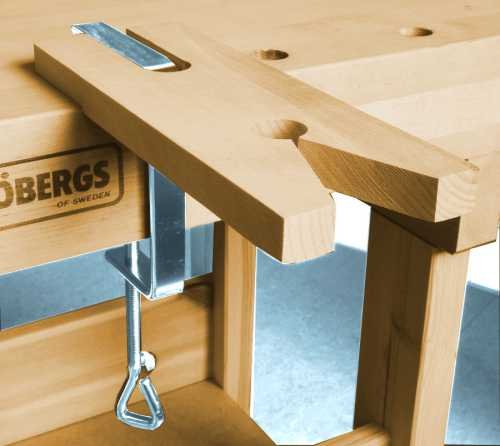
If it is your ambition to manufacture and sell ship model kits, buying a laser cutter might be something to consider. For a one-off proposition, a laser cutter seems to me to be an extravagance - a really huge extravagance. The computer portion is an immense time sink. I am going to guess about your experience and skill level. For what you wish to do, You might consider treating yourself to a high quality but low tech and old school tool. A fret saw - Knew is expensive, but the joy of using a well made precision tool is .... especially when a laser is the alternative. Also a proper support surface - the picture is for the general shape - this is an easy enough DIY using a piece of 1/2" or 3/4" AA or Birch plywood. If you do much of this, you will come to know if you need an electric scroll saw or a 1/8" blade on a benchtop bandsaw.

-
Up thru the hull planking stage, we are building in different worlds, POF vs POB. A frame that is overlapping timbers is mainly subject to sheer forces while being shaped. The same while being planked. For deck components being knocked in a lateral direction seems more likely than their being levered up. For planking itself, I see at least two possible stress sources. If a plank is not pre-bent to sit on the hull, if it has to be held down until the bond cures to keep it from going back horizontal, it will pull up on the bond forever (noemal stress). If it has been bent thru the thick dimension instead of being spilled, It will exert a lateral force (sheer) and a twist (normal) even if it has been pre-bent and is a push fit at assembly. Nature never sleeps. I think it was Underhill, that imprinted this at my beginning of this, but the belt and suspenders philosophy ( chemical and mechanical bonds for as much as possible ) but it has stuck like an obsession.
-
From a practical perspective, should not the force arrows on normal stress (sigma) be at 180 degrees? What I would call prise resistance (because I have not seen the technical data before now.) To stack the deck against CA a bit more, most of the stress that wood to wood bonds encounter on a ship model tend to be sheer. When the bias and any criticism is arbitrary or from a traditionalist position, snobbery and elitism is a valid accusation. For wooden ship models, that would apply if the elitist preference was hot pot hide glue. When the suggestion to avoid CA is based on demonstrated, and unnecessary failures inherent with the material, ( often experienced first hand) , it is more of a flashing warning light that is apparently unsuccessful in resisting the power of modern product advertising, and illusory convenience factors.
-
I was able to source some Holly that was on the hoof. In order to defeat the competing Blue Mold invasion I immediately cut it into 1" billets and removed to bark, and sealed the ends with a thick coating of leftover latex house paint. I purchased a 4' x 8' sheet of 1" foil faced house insulation foam. I cut it into 4 x 4' pieces to make the 4 sides of a box. It does not need to be either strong or tight fitting. I fit it into an open shelf in my garage. The ends were made from the 2 x 2 x 1" project Styrofoam that Home Depot sells. The foil was on the inside face. A couple of ceramic surface mount light fixtures and a 200W and a 100W incandescent light bulb generated enough heat - often 200W was enough. A surplus computer muffin fan on one end was sufficient to exhaust the heated humid air. I had a digital - remember the highest temp thermometer - to make sure it did not get too hot. I stickered the billets. A probe moisture meter sufficient for our needs is not expensive. 3 months was more than enough time. For a temp, I just guessed about a temp that was above what the mold could survive. Too much heat and the wood may case harden instead of allowing the water in the middle of a billet to migrate out. There is probably a Zen type factor in all this. You may be able to stay ahead of the checking with your "Lilac" by using a similar setup. It will still be a month or so before the sap starts rising, if you wish to try this year. Washington state appears to have a significant Apple growing base. You are maybe not too far north for there to be Apple trees? Apple wood is King. But the only real way to get it is to harvest your own. The hot box might save you the best part of year in getting a dry supply to use. Not far south of you is a supplier of Pacific Madrone. (Portland). The wood reads like it can easily substitute for Pear or Black Cherry. It is a bear to season. It requires a specialized kiln operation. It is not a DIY species per my reading. It also wants to be picked over in the yard to get the color and grain that is desired.
-
You do not provide a geographic location for where you are at, but in the US most local hardware stores stock Birch dowels. Now, using commercial dowels for spars is a risky but common option. A cork borer type cutter is used on a board. The straightness and parallel orientation of the grain is a pure chance factor. A dowel with grain that is not dead straight will tend to take a dogleg bend over time. A way to avoid this is to start with a board with straight grain and is of a species of wood with scale appropriate grain and absence of visible pores. Use a froe to split out a square cross section stick and work it round and tapered. Not germane to this particular problem: We all probably started with plastic kit models of whatever. If a part is missing or malformed, it is probably necessary to interact with the kit manufacturer to get a replacement. Wood kits of ships use a material that is available from many sources. The cast metal and PE parts are get back to the manufacturer parts, but for the wood, finding outside sources will probably gain you better quality wood to start with and it is the usual way to cross the barrier over into scratch building. There is a fundamental difference in the mien behind plastic and wood in respect to kits. Because so much on a wooden ship is basically the same over the wide range of vessels in its slice of time - varying only in size depending on ship size - I suspect that some kit instructions are loosey goosey in the HOW in their instructions because it is like describing water to a fish. It probably seems redundant when you know what sort of information is generally available. Plastic is subject specific assembly and each needs specific instructions. Wood is fabrication from raw materials and the instructions are a trade set of skills.
-
Wood filer
Jaager replied to Andre Gotty's topic in Building, Framing, Planking and plating a ships hull and deck
While I prefer yellow PVA with water resistant additives - Titebond II for wood to wood, it dries amber, so mixing it with wood flour for a filler will produce a patch that is a darker shade. White PVA dries clear. So for homemade filler, this is a better choice. No water. Fresh PVA. Too much wood - it is stiff and crumbly - it needs a workable consistency - too little wood and it is just a clear plastic with wood salted in. A more interesting variable is the particle size of the wood flour. 220 grit is probably about small enough and 80 grit is probably a size too large. I suggest wood flour in the 100-220 range. -
Making and using a draw plate
Jaager replied to Don Case's topic in Modeling tools and Workshop Equipment
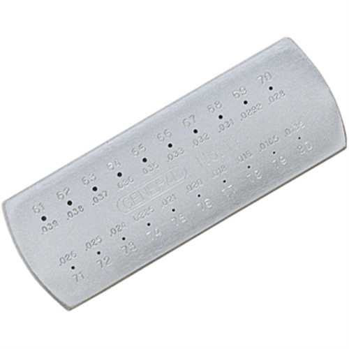
I think: This will cost more in time and tool wear than any perceived savings from DIY. The Byrnes is on balance economical. You can also use two tools that you will otherwise need to have anyway: General Tool #15 1-60 drill gauge. General Tool #13 61-80 drill gauge. Both are SS and can be rubbed on a stone to renew the edge. Drill bits go astray and the gauge is needed to identify the size. If the alternative ready made option is an actual jewelers draw plate - a bad choice - expensive and made for actually drawing wire. The sizes do not match wire gauge sizes. They must be used from the wrong side, the taper does not help in grasping the bamboo and using a stone on the small size will enlarge the holes because of the taper (although that would take several lifetimes of rubbing). In my experience: There are a blue million species of bamboo - which one is used in any particular bag of bamboo skewers no way to know. Some are soft and draw easily, but are fragile. Some are hard and fight being pealed into ever smaller diameters. The interval between each drill number is often too wide. Going back thru the same hole more than once but at an ever increasing angle might keep a stick from freezing up in the hole and being the devil to push out. The harder species are worse at this. It is not easy to get a grip on the stick. It is difficult not to crush the tip too much to even get back thru a second pass without shaving a new point. It is about an every pass step - long skewers help make it provide enough final length - after a tedious, frustrating, and time consuming process. I have yet to find an ideal gripper. I have the gripper used to pull wire - scissor action - coarse teeth - wants to crush - even with a piece of sandpaper between the surface and the stick. I bought parallel grip pliers to try and something else featured here that is waiting for testing. Something with a groove for the stick may reduce crushing. A bag of plastic test tubes and a test tube stand is a way to store the variety of finished trunnels sorted per diameter. Some sticks are not going to let you draw them down as small as you want. They are still useful.
-
Improving a Homemade Thickness Sander
Jaager replied to Roger Pellett's topic in Modeling tools and Workshop Equipment
Roger, There is probably a bit more control, but a hand crank feed or direct push of the work into the rotating drum - still involves a human factor into the constancy of the rate of feed. A motor driving the feed table would solve that. I have never used one, or even seen one in operation, But does not a full size planer that uses cutting blades also have a motor driven feed? I sure would not care to get my fingers near those rotating blades. With a sanding planer, all I get is interesting fingernail tips. -
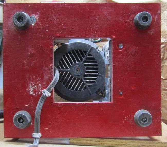
I have no insight into what jobs a drum sander would be help for with POB scratch. My guess is that most of it involves a square angle. It would probably do way more harm than good if used to bevel standard moulds. For POF frames, the bevel is never a constant angle, it must be done by eye, so a tilt serves no purpose. The dust generated by a sanding drum is a really significant volume of fine air borne particles. Dust extraction is necessary. It has a horizontal angular momentum of some velocity so if a shop vac nozzle is close the dust goes there rather than falling into the box with the motor. My guess is that the motor is an induction motor. The cooling of the windings is by convection and there is a grill of sorts at either end of the housing. Saw dust will tend to pack around the windings and the motor will overheat. I have never seen a brush motor that is as large as 1/3 HP. The presence of sparking: only if there is a short in the windings? The motor will get hot, but paper ~= wood - it ignites at 415 F ? I would think that the motor would fry and freeze up well before that temp was reached. My prediction about your construct: a closed back will make the box into an oven after a relatively short working time. With just the back open, the working time will be a bit longer, but it will get hot -not enough free air exchange. The solution is to remove the front panel. I used 1.5 inch angle steel (with holes) to do what the front and back panels on your box do - hold the sides at a fixed width. Cut a big hole in the bottom panel where the motor bracing attachment ain't. Put 1.5 or larger rubber corks at each bottom corner. It reduces vibration noise and allows for air flow from below. Now that I think on it, 4 pieces of angle steel could replace the bottom panel. Two outer ones to fix the sides in position and two in the middle to hold the motor. With the corks holding it up, there would be optimal air flow from below. Buy a piece of the 1/4" thick stuff that peg board is made of, just get the version with no holes. Make its dimensions a push fit inside your box. Drill a 1/2" hole where the motor shaft hits it. File the hole a tad bit larger. With a TEFC motor, it can be sitting on the motor housing, with an open motor, some gap is necessary. This shield will keep saw dust from getting to the motor. Free hand bevel sanding - remove the table. You are going to wish that the sides were not so high above the motor. They should be about level with the top of the motor. The table need not be a flat plane board. It can have "feet" to position it up/down that sit on the side boards. For dust collection - first I reverted to my previous life and bought a lab ring stand and finger clamps to hold a crevice tool at the dust generation site. The stand does not weigh enough, the finger clamps are too weak. I replaced it with something sturdy that works. It needed a lino washer on the positioning bolt to hold it at the required angle. About the sleeveless drums, the backing pad is beveled at the slot - no bump. They have a 1/2" socket with a set screw. They come with a 1/2" post so that they can fit in a chuck. The rod can be removed and the drum can fix directly on the 1/2" motor shaft.

-
My old thickness sander was two pieces of Hard Maple with a 1/2" shaft bonded in the middle and the wood turned using the shaft as the chuck attachment. For a drum sander table, the actual drums? It may be worth your time to visit the Peachtree Woodworking site and think about their sleeveless drums I suggest the minimum if you work at a larger scale 3 x 6" 3 x 2" 3 x 1" 3 x 3/4" The core of the 3 x 3/4" is steel, so if the rubber pad is removed an even smaller drum is possible. The Norton 10X sandpaper holds up, and unlike your thickness sander drum, the medium is held by a mechanical attachment. The 10X has a non skid backing that rejects rubber cement and probably contact cement. The thickness sander wants Klingspor cloth backed media anyway.
-
1700 rpm - no RPM adjustment - faster than this burns the wood. If this is for an occasional use, you may get by with an economy quality motor, but for serious work, going cheap may prove to be more expensive. Big box home improvement stores have large size Erector Set type steel and bolts. These can hold the motor vertical and along with and "T" nuts, attach 3/4" plywood sides to the base. Easier to undo, or adjust - glue is not a friend for this. They also have free samples for Armstrong lino that can be cut and used as sound dampening "washers" and large rubber bottle stoppers for feet to block vibrations and elevate to allow for air flow from below.
