


Jaager
-
Posts
3,084 -
Joined
-
Last visited
Content Type
Profiles
Forums
Gallery
Events
Everything posted by Jaager
-
An old method is to use a cutoff sharp end of a nail. Drill a hole in the bottom end of the mast. Insert the cut end of the nail into the hole and have just enough of the point sticking out to seat into the "deadwood". If you had cut the slot for the mast too deep, a longer piece of nail can be used to raise the mast a bit. The size of the nail depends on how large of a hole is drilled into the end of the mast.
-

Where to buy wood stain?
Jaager replied to Dollburger's topic in Painting, finishing and weathering products and techniques
Sealer seems to be an ambiguous term. Sand n' Sealer is a product type meant for full size furniture made from open pore species like Oak, Walnut, Ash ... It is thick and has solid particles meant to fill the pores. It is generally better to use a species of wood that does not need any pore filling. It is really out of scale thick. If by sealer, a clear top coat is what is meant, there are two general schools of philosophy. Polyurethane - which comes water based and organic solvent based. It is a plastic, and to me, looks it. Many here are devoted to wipe-on poly. As Bob Cleek writes, it is diluted regular poly, that is just more expensive and has good advertising. Old fossils prefer shellac. - lots of posts about it and how to use it. Thin and shine depends on how many coats or if it is buffed with a fine abrasive. There is also solvent based - usually termed varnish, which is a polymerized natural oil, like linseed, Tung with maybe some shellac added in. Generally thin, but getting an even coat wants practice using it. A primer is usually half concentration shellac or oil that penetrates, and sets up a base for additional coats or paint. The can of stain should give directions for any pre-treatment - follow-on top coats are a matter of personal taste and the final look that is desired. High gloss anything is to be avoided. Matte or flat or egg shell is a better scale appropriate finish look -
Allan, If I am reading it correctly, what you are doing is lofting new mould shapes at the positions that you have selected. It is more work, but it would still exactly replicate the hull. The English seemed to go to laborious means to get their frame sides to define the sides of their gun ports. The French and North Americans seem to have just used more material and less space in their upper works and cut the ports into the framing timbers. I make it a goal to only need to use the existing stations from the Body plan to use as patterns for my frames. I do not do well at drawing curves and doing something like 200 of them instead of just isolating 20 or so station shapes is weeks if not months quicker. It is also less prone to me induced artifacts. This means that on average, I am shaping 2-3-4 bends (4-6-8 frames) and their intervening spaces as a unit. I fill the spaces with low cost Pine held using double sided tape to make it solid and protect the frame edges. I make everything above the main wale a solid wall - no spaces - I find the actual framing there ugly anyway, so I hide it. In your place, I would use my method instead of POB. I would use Yellow Poplar. (Framing lumber Pine will do - specially if you can get No.1 material. HomeDepot "quality" stuff is No.2) The layer thickness where there would be frames can be any convenient dimension. The sum of the layers needs to be equal to the station interval. It is way more work, but the thicknesses can be set to frame the gun ports without any later cutting in. The wood species there can be something more pretty than Yellow Poplar. I used Rock Elm for Renommee gun port sides - a red close to natural mineral pigment red. By using pin alignments outside the actual frames, the layers are exact and there is an identical pattern in the identical location on both sides of a stack- The bevels on both sides have their patterns. No baseboard needed. Getting the stacks joined properly requires care. The result is a solid base for single layer planking. If you fill the gaps between moulds in POB - My way is probably quicker and if you have the machinery - a serious scroll saw (I use 1/8" blade on a 9" bendtop bandsaw) and a drum sanding table and a drill press - the alignment pins need a blue million holes. It makes for a better looking under the planking hull that is hollow if you want to include any guts.
-
Where to buy wood stain?
Jaager replied to Dollburger's topic in Painting, finishing and weathering products and techniques
I will guess that your kit is not from a boutique supplier based here, so the quality of the the wood species is questionable at best. This makes using a dye relatively pointless, since the basic material does not warrant quality treatment. So, using an actual stain (semi-transparent paint) would be an improvement. Checking on WoodCraft's site, you can get 1/2 pint cans for ~$12.00. A local hardware store may do as well. If the stain company has a shade that the store does not stock, one that rings your bell, they can probably special order it. I would go with solvent based over water based. The water will raise the grain. You can get around this by pretreating with 10% PVA in water and refinishing after it dries. Test on scrap. But good ventilation and latex gloves and oil based will save the step. Ignore the supposed waste, it may last longer that you think if you seal it well. Paying 10x's more per volume for a smaller bottle may not really be wise economy. -
Allan, I say this about the spacing of moulds on a POB build. It may be only a slight difference in final shape, but altering the placement of the moulds along the central spine to a different position from those defined by the plans is not a good thing to do. Especially if the reason is to have the moulds be at regular and equal distant intervals. This does change the hull curves. This ship seems to be singularly unique in that it has four sets of Station intervals. There are 4 sets of frame thicknesses and space thicknesses. It is fiercely complicated when compared to similar monographs. I am saying that by moving the station intervals so that they are equally spaced, just for looks does not do anything important. The moulds should be hidden by the planking and not seen anyway. I do not see the point for having symmetry there. But this is my particular OCD. It seems that even the designer of the plans says that moving the stations and rotating them CCW 1.2 degrees machts nicht anyway. (For me this injects certain questions about the author.) The 17th century hulls (most of them. anyway) were developed using three stations. The main one at the deadflat, one forward and one aft. The various profile curves that define where are the arc centers produce the two smaller moulds at an arbitrary position fore and aft chosen by the architect. But the hull shape can be changed by sliding these outer moulds along the keel. Move the forward one closer to the bow and the entry is more buff. Move the after one closer to the stern and the run there is fatter. (If I understand it correctly, Dutch shipbuilders did this with three bends on the ways, instead of on paper. The English and French had more politicians involved and less trust in the shipbuilders, so they started with paper/parchment.) The waterlines, buttock lines, diagonal "proof" lines were to check for unwanted hollows or bulges. These guys did not have test tanks, laminar flow tests, eddy checks. They used experience and preconceived prejudice as their "scientific" tests for proper hull form. Moving the stations is redesigning the hull shape. All these problems are minor factors. This ship is special. It is elegant. It is about a magnitude above any competitors in beauty. Even if CRI-CRI is using the awful POB method, he seems to be capturing the hull curves so far.
-
Language differences aside, that is not a frame. The usual name is "bulkhead". It is not really a bulkhead either. What it actually is = a "mold" or "mould"*. From my time around microbiology, I prefer mould - even if the site spell checker does not. It also does not like a lot of other words we use, such as "futtock". Imagine doing this at 1:48 as provided in the monograph? * Old Ben, Ben Lankford was the first the make a point of this back on Clay Feldman's listserver.
-
As an alternative you could cheat: Part 204 - chock piece - seems the extend to the top of part 202B - upper head rail. I would place the two gammoning slots in 204 - just above the upper head rail. This would save having to move the LWL or hide the carving. In real life, if the boatswain, I would probably try to place the gammoning where the carving is and adjust the pattern to include it.
-
If the terminology follows tradition, you have a species of Maple there. It is close enough to Hard Maple for the differences to be academic. It is also a local commercial hardwood for you. Harvesting, seasoning, and milling your own wood is tricky to do and a lot of work if it is not a part of your usual work. The rewards generally match the necessary investment in time, equipment, and skills if the species harvested are those which are not to be had by any other means. This would most often be a fruitwood, box, if lucky, hawthorn, Cornus and the like. That editorial caveat out of the way, It needs air circulation to dry before a fungus gets it. It needs protection from rain and snow. It needs protection from borrowing insects. The rate of water loss from various surfaces needs attention. The wet finger rule is seasoning requires 1 year per inch of thickness. The water will leave much more quickly from areas of open end grain: cut ends and where branches are cut off. Left uncontrolled, the difference in rate of water loss will produce internal stresses. The wood will split and check. In the worst cases, the result is toothpicks. The open ends must be sealed. This needs to be done concurrent with harvest or soon after. There are many materials that do this, but quick and dirty is a THICK coating of leftover latex house paint. Recoat as any splitting there shows there is not enough of a barrier. Bark slows the rate of water loss from the side grain and there also may be eggs or larvae of wood eating insects in it back from when it was standing. Leaving the bark on invites insect damage, a slower rate of drying, and not discovering any existing rot, which would result in a wasted effort. Air circulation around each piece is important. Pieces of wood are generally used for this. Over here, these are called stickers. The process of stacking the drying wood using the stickers is termed "stickering". It speeds drying time, making handling easier, and may save on loss to splitting if the logs are immediately reduced to billets. One inch thick is OK if you do not need stock for larger scale POF frame stock. Two inch is better if you do need this. Getting logs into billets is most efficiently done using a band saw. It is a royal PITA otherwise and generally involves serious loss to kerf. Length, from the lumber yard, the boards generally come in 8 foot lengths. My first outing involved the yard bisecting to 4 foot. This is still impractical. For a while, I cut them into 16" lengths for my bench. It is a bit fiddly and short, and now I find 2 foot lengths to be my sweet spot. Does your garage have rafters/ trusses? Is there room there for drying wood? Is there an attic in your home? Otherwise, your outside stack will need a blue tarp and probably a new one every 6-12 months.
-
I suck ripping planks with my Byrnes saw
Jaager replied to bigcreekdad's topic in Modeling tools and Workshop Equipment
It sounds like the blade is wandering. This is more of a problem with a bandsaw - and it occurs with me even with a high power quality machine- IF the blade is becoming dull - continuing on usually produces a BANG fairly quickly - - snapped blade - so there is no advantage in pushing. SO, in light of this, Iis your blade too thin? Are there too many teeth on the blade for the thickness of the stock? Is the blade becoming dull? The Byrnes saw motor is powerful enough to drive a too thin, too many teeth, dull blade thru too thick stock without slowing down, so the blade will do the protesting. -
I was thinking about your wale bending task. Bending thru the thick dimension is fighting what the wood wants to do. But would it be easier to bend a 1/4" x 1/16"? I was shocked by kits doing wales by superimposing a half thickness wale over the complete first layer planking with a double layer hull POB. If the wale is two layers, the evidence would be hidden by the planking strakes above and below. It is heretical, but you could pretend that the hull is being girdled.
-
I did some more armchair experimenting: Would it help to use cardboard that is close to plank thickness? Would it help to use a penetrating treatment with a varnish on both sides to stiffen it? Would a plastic sheet that is thick enough to be stiff, but thin enough to cut with a sharp violin type knife and straight edge work better? Once the pattern is refined to make a good fit, it can be transferred to two layers of planking stock bonded with something like double sided tape. This way P&S planking can be spilled together. About half the work and a better likelihood of bilateral symmetry?
-
Mark, When you measure out a plank, do you first transfer that to a mock up from something like poster board to check the fit, before actually cutting wood?
-
If you included a 1.2 degree drag when the central spine was shaped,the stations will be vertical directly from the plans. With a large solid central spine, a POB fabrication appears to be the method here. The underlying spine/solid molds structure of POB is so unattractive that it all but demands to be totally hidden. When it is hidden by planking, the regularity and symmetry of the mold intervals is moot. Why alter the intervals? Changing the spacing of the station intervals will have a small but significant effect on the hull shape, if the stations in the plans are used as mold patterns. If you loft new patterns at the new intervals the hull shape will be as designed.
-
One factor that may serve to make veneer a bit difficult is in how much if it is derived. The log is rotated against a blade. The veneer comes off like unrolling paper towels. It is totally unnatural as far as grain behavior. It saves on loss to kerf though.
-
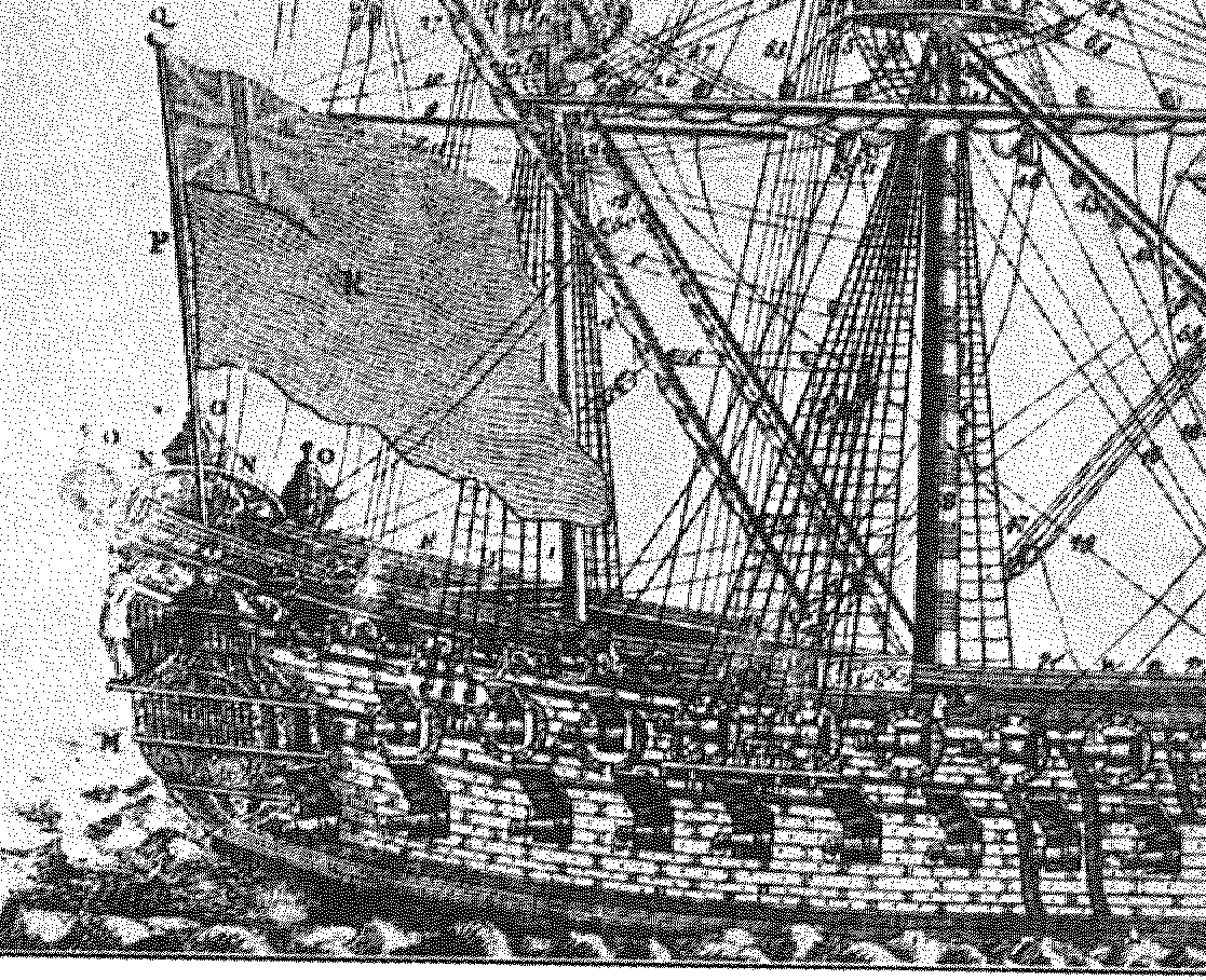
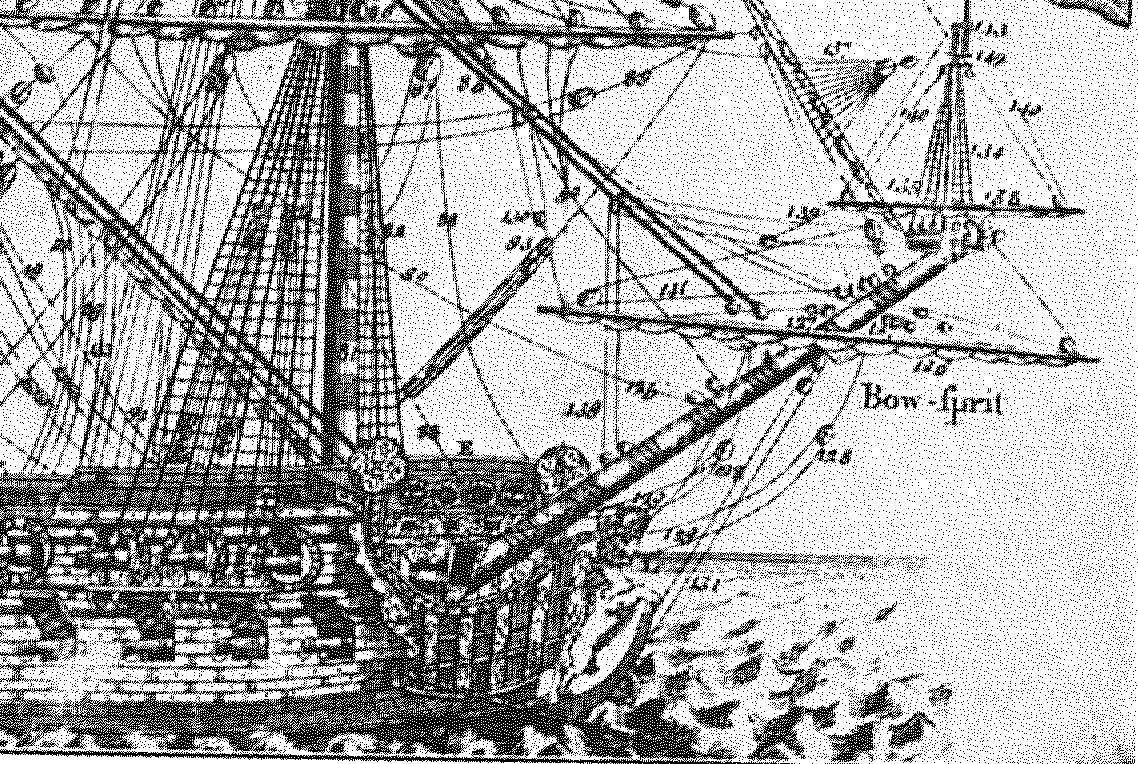
I have a reprint from ~ 1968. Given the poor resolution, I suspect that the original first edition was significantly larger and perhaps the illustrations at the front were originally even larger loose sheets. The scan is from a Brother 3-in-1 printer scanner. I think 400x400. The 1200x1200 pixel version was not any better. I have an old flip phone, no text even. I have no use for a smart phone. For me, it would only be an expensive target for telemarketers and other thieves phishing.
-
Lets see if this works:


-
Until you suggested it, not so's you'd notice. Thank you for the additional possibilities. In sniffing out your trail, I found that Amazon has 2" disc sanders -at least. I am not sure that the chucks are all that I would need, I will have to think on this. I did put a couple of manicure motors on my Amazon wish list a while ago, but I have Dremels, so no need for them. For drilling inside a hull, I have more than enough small DC motor with chucks that will fix +/- #70 drill bits. Most of my plans have lines for top of the beams/bottom of the deck at the side. I include that data on my frame patterns. All of this has lead me to possible way to site the clamps. Cut a series of strips of wood that are the thickness of the deck beams. Pin them at the sirmarks for the bottom of the deck and push the clamp up against the bottom and bond it.
-
Cutting too deeply into a plywood spine may not be all that good of a practice. The bonding surface for the keel needs to have an adequate surface area. If a supply of veneer of an appropriate species of wood can be obtained, a layer of veneer can be scabbed onto the outer surface of the keel on either side. On models where the rabbet was done poorly, this could serve as a rescue. Going out for a rabbet rather than chiseling in would appear as the same result.
-
The glue that they used is most likely a version of what is now termed glue pot hide glue. In the several discussions here about CA, it was stated that the present formulations of CA have a longer life for an effective bond. I still will not touch the stuff, but you will not have any conflict if you use it unless you build something for a serious museum. Given that the fad with museums is electronic flash, it will probably be another generational turnover before or if there is a pendulum swing back to bunches of physical specimens on display. I second Gregory on the physical attachment being used in addition to a chemical bond.
-
I would find this to be a rather pointless DIY exercise. There are probably domestic suppliers, but these are available in abundance from AliExpress, from many shops under their umbrella. There are flat disc in 1", 2", 3" diameters With hook and loop mount or adhesive mount. There are 1/8" shafts and 1/4" shafts available. WoodCraft and MM offer inside bowl sanders types that have a foam layer just behind the abrasive attachment, but the foam is not hardy and the rotational force tends to tear it if you push down as hard as I am want to. I think these are 1/4" shaft though. As Bob says, bulk removal of hardwood needs a more powerful motor than a Dremel. Now, what I would like is a flex shaft tool mount chuck with a 45 degree angle. 90 degree I have, it gets inside a hull, but 45 degree would be the sweet spot.


-
Cant frame R+S
Jaager replied to Don Case's topic in Building, Framing, Planking and plating a ships hull and deck
There is nothing wrong with upside down. I framed Kate Cory using that method. The experience gave me a compulsion to find an easier way to loft and build a POF hull. I was just suggesting his framing convention without meaning to endorse the whole of his method. The all bend, room = space convention was also from Davis, so it predated Hahn by decades. As near as I can tell, the more authentic framing started with our exposure to Model Shipwright and soon after, Boudriot's ground breaking books about the building of a Sane designed 74 gun warship. It only took them about 40 years to offer the unbound plans for sale. Those books are still the deep way to understand wooden ship building. I think that the build logs here showing a complete POF replication of various ANCRE monographs or the Swan series may be offering a distorted view of how complicated a proper POF hull needs to be. -
Cant frame R+S
Jaager replied to Don Case's topic in Building, Framing, Planking and plating a ships hull and deck
To just use the term frame for everything there can get a bit convoluted. Frame is a series of timbers that are all in the same plane. It may be Floor + futtock 2 (F2) on either side + f4 on either side + a half top on either side ( multi deck ship ) It may be a half floor or cross piece or cross chock + F1 on eiyher side + F3 on either side + a top timber on either side Both are frames. Where the floor butts against F2 is in the middle of F1. A bend is one of each of these frames, joined side to side (the original meaning of scarph) - The butts of each frame has an overlap support from the partner. Bend is not a universal term, but it easier to type than 'paired frames'. These are the parts of a bend: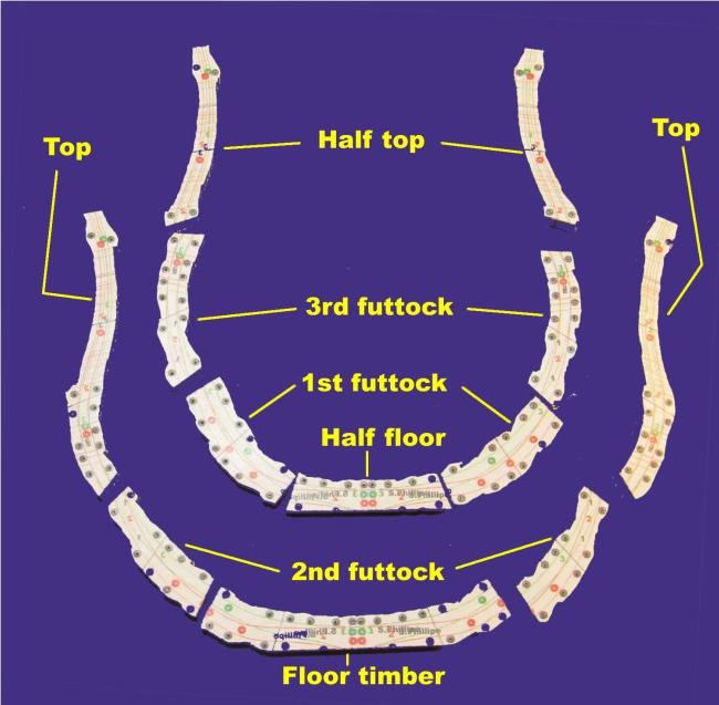
-
Cant frame R+S
Jaager replied to Don Case's topic in Building, Framing, Planking and plating a ships hull and deck
OK, beam 28' SR has floors sided 11" Meade about 100 years later also has ~11" for a ship of this size. 25.5 - 22 = 3.5" of space. A bend would be a pair of 11" frames. Prediction: If filling frames are present and the stations at 51" The stations would be the midline of a bend. There would be 7" of space and two filling frames with 3 space gaps. The spaces would be 2.33" each. If the stations are at 3 R&S intervals - 76.5" intervals, the mix of bends and filling frames can be a bit more creative. Most RN plans would have the stations at 51" intervals. With an American ship the plans would have a high probability of the middle 1/3 of the hull having with stations at 102" intervals with that changing to 51" intervals as the slope of the bevel becomes greater at each end. I suggest that with this being your first effort at POF, go simple. Just frame using all bends. Even more approachable would be Hahn style - make the frames sided 12.75" use all bends and omit every other bend. This has a more interesting visual presentation. Framing it per scantlings would only have ~14% as space. Close to being a wall of wood. The Hahn style saves time and wood. -- I am not suggesting that you use his upside down fabrication method. -
Cant frame R+S
Jaager replied to Don Case's topic in Building, Framing, Planking and plating a ships hull and deck
Allan, I was being a bit snarky there. I suspect that there was a weight reduction factor involved as well as economy and conservation. Unless someone from the time wrote an explanation , we can probably only speculate about their reasoning. Today, it would make for a paper or series of papers in a professional journal. It is not that S-Philippe has no no correlation between Station position and R&S. It does. The complicating factor is that there are 4 different sets of intervals. The R&S matches each of the intervals. There are just 4 different sets of R&S, There are 4 different stocks thicknesses of framing timbers required. It is a complicating factor for anyone building this ship POF. I am perplexed about Litchfield. Unlike how we modelers traditionally loft frames on a drawing board by measuring waterlines and buttock lines to plot the shape for every bevel of every frame, an actual mould loft only expanded the Stations to full size on the floor make make the patterns. Richard Endsor goes into detail in Master Shipwright's Secrets - although I am still not sure the patterns they made also had the sirmarks for the frames between the stations. The guys with the adz could have faked it using the ribbands. Perhaps it was done both ways depending of the yard doing it. At the beginning of my framing method research, I was using Marquardt's HMS Beagle monograph. I messed with designing for futtock sided reduction and filling frames. I figured out an idiot proof way to do it. But, most of the reduction is above the main wale and the extra attention and time was just not worth it. I also go with square frames all the way - no cants. At the bow, I come in perpendicular - parallel with the stem. Aft, I do square up to the fashion timber. I do not bother with: sided reduction either fore and aft or towards the top timbers. The framing above the main wale looks more like house carpentry to me, with no real curves, so I hide it under the planking. Because I hide it, I do something even worse and make it a solid wall above the main wale with no spaces. It really fixes the frames in place, I also make the deadwood go from keel to keelson in the spaces. This locks the bottom. I see indications that at least some actual ships did this part way. They left a gap at the bottom for bilge water flow, but that only needed a few inches. Display models do not have to worry about bilge water, so I go all the way with wood. -
Number of floor timbers
Jaager replied to Don Case's topic in Building, Framing, Planking and plating a ships hull and deck
You have some wiggle room on the scantling specifics. Your ship was built by a private yard on spec. They were not restricted by Navy Establishments. They were probably restricted by the rules that Lloyds required. Anyone buying it would also want the insurance. Also, a sloop built for warship duties would probably have scantlings that were more beefy than a merchant vessel of the same size. The merchantmen that I have observed had more space. The timbers may be the same dimensions but the wood part would be a lower percentage of the whole. For warships from the 1770's thru the 1780's, at least at the level of the floors, the space was 1-3" of the whole R&S. A model with the frames on view would pretty much show as a wall of wood. This is most likely the reason that Harold Hahn omitted every other bend with his plans for Revolutionary War era ships. There is not much point in showing the framing if it would look about the same as a hull built by carving a solid block or carving lifts. The function of a merchantman was not to withstand cannon fire. It was not required to spend years on blockade duty. I am not sure that the additional weight of wood made a difference as far as cargo, since they all needed ballast to get their swimming body low enough. It would have made the ship less expensive to build.


