


Jaager
-
Posts
3,084 -
Joined
-
Last visited
Content Type
Profiles
Forums
Gallery
Events
Everything posted by Jaager
-
 That is indeed the major question. i.e. is a different curve drawn for each beam? If a master pattern is used for a whole deck, The beams would still be the same thickness along their length. As each beam gets shorter, the height of the crown above the chord is less. The ends of a beam would be up to spec, but a curve connecting the crowns would be flatter than spec. As for model scale effects, at 1:48 and smaller the difference in a deck curve that is an ellipse/parabola vs the arc of a circle is beyond our ability to discern this is my take home of the published consensus for 50 years. I bought a plastic drafting tool long ago that forms an arc along the top edge. The radius of the arc decreases as I turn a dial. If I accept an arc as my curvature, it makes drawing the proper curve for beams of different lengths pretty easy to do. I just turn the dial until the arc connects the two end points with the crown. I have long seen that the gun-ports go from rectangle to parallelogram as the ends are approached. I just never noticed that the deck beams also do this.
 -
Model shop bandsaw choice?
Jaager replied to tooter's topic in Modeling tools and Workshop Equipment
If If tooter has some serious tools, I can see that getting a 220 V. line into a unit could be expensive. If he does not feel physically up to the task, a helper with some wood shop skills could be hired prn. Or, skip the physical ownership of the tools work a deal. Trade the whole kit to someone who would use it and get them to do the major tasks for him. He does not say where he resides, but if he is lucky, there may be other ship modelers that live close enough to to work a cooperative deal. There is a woodworker guild here - with commercial cabinet makers involved ( I think) - another source for a possible deal. I suspect that the amount of money from a tool liquidation would be marginal when compared to the acquisition amount. -
Greetings Mark, I believe it was in the NRJ, maybe in the 1970's. Or possibly Shop notes v.1. When I was a lab rat, I kept a card file of references to my pack of journal article photo copies. The cards had relevant quotes about the key points. For ship modeling, the best I did was just the basic title etc. in a database - A quarter circle with a radius that is the difference in height between center and end of the beam. The radius along the base-line is divided into 4 equal spaces and a perpendicular drawn at each of the 3 points. The distance between the center of the beam and the end is divided into 4 equal spaces. The three perpendiculars moved out to the three points along the beam half length. A curve connecting these 5 points is an arc of a circle. or The quarter circle has a fan of three lines that each define 4 equal segments of the quarter circle arc. The perpendicular height at each of those 3 points is instead along the same equal distant segments of the beam half length. A curve connecting those 5 points is an ellipse ( or part of one). The point being that an article showing these two geometry exercises = a little semicircle with perpendicular lines inside and a big arc above it and another with a fan inside the little semicircle and a different shaped arc above it, the article in question has been found. Maybe I have confused an ellipse with a parabola. I checked HIC's Boat Building and he shows a different way with different sort of fan. I also seem to remember a perpendicular at the end of the half beam with a fan drawn from the mid-point. The intersection of the 3 section perpendiculars with their fan line: connecting those 5 points is another sort of curve - but maybe that is another way to get an arc? From a fast scan of HIC, I think he is saying that the curve for each beam is drawn to compensate for the difference in length. I also recall seeing Bob Brucksaw (I think) using a disc sander to shape the beam curve. The beam was clamped at the end of a long stick. The stick had a pivot at the distant end. Swinging the stick would allow the disc sander to produce a smooth and reproducible arc on the beam. I have always been stumped. How do you get a fixed pivot point that is level with the sander table and be so far away? The length of the stick will also need fine-tuning. I did a database search, perhaps of of these has the answer: A JIG FOR CUTTING DECK BEAMS WEBB,WM G MODEL SHIPWRIGHT , 1987, 60, 52-55 DECK BEAM CONSTRUCTION BRUCKSHAW,ROBERT V NAUTICAL RESEARCH JOURNAL, 1977, 23,42-43 DECK BEAMS - ADDITIONAL NOTES FLEMING,EDWARD S NAUTICAL RESEARCH JOURNAL, 1977, 23, 99-100 DECK BEAMS AND CAMBER HOBBS,KEITH M NAUTICAL RESEARCH JOURNAL, 1978, 24, 43-44 PLANKING VISE, CONSTRUCTING DECK BEAMS, TURN SQ STOCK IN 3 JAW COLE,N R NAUTICAL RESEARCH JOURNAL, 1978, 24, 100 DECK BEAMS MATHEMATICS OF CAMBER BRUCKSHAW,ROBERT V NAUTICAL RESEARCH JOURNAL, 1978, 24 , 152-153 DECK BEAMS AN EARLY SURVEY OF THE WORD CAMBER SEARLS,DELMAR E NAUTICAL RESEARCH JOURNAL, 1979, 25 , 98-99 Dean
-
My mental vision missed the effect of the slope as the ends are approached. Thank you for pointing out the additional factor to add to this equation. Since the deck clamp follows a curve, if the beam sits directly on it as is, the beam top surface has the necessary bevel. No longer vertical are they. If the decks are completely planked, who is to know? I suppose the beams at the hatches at the ends would need a bevel to fake it. That would be a lot less work. Yet another reason to stick to modeling the actual surface and forego showing the underlying structure.
-
As I understand it. The actual curve is an ellipse and not an arc of a circle. I see the advantage for this. It would have a more flat middle section and accelerating run off as it approaches the side. I also suspect that variations in shaping the beams would probably be greater than any perceived difference between an arc and an ellipse at model scales. My question is about how the curve is determined for each deck beam. If the mid-ship beam is used to determine the curve for all beams for a particular deck. If a parallel curve if used to shape the underside of the beams and the thickness is constant along a beam, I see the following: All of the beams can be shaped as a batch. Either a block is shaped and each beam if sliced off - much loss of shaped material. Layers the width of each beam can be temporarily glued into a block, shaped, and each beam released by reversing the glue bond. Or the same curve pattern can be used to shape each beam individually. If a deck clamp is used to site the beams: With constant thickness. The crown has a down camber as the width decreases. As the width decreases the height of the crown above the line of the bottom plane decreases. The rate of change in slope of an ellipse is lost. But that is mitigated by the water running down hill to the mid-ship as well as to the sides. If the spirketting is used: butting the top edge up instead of the bottom edge down, I see the result being the same. If each beam has its own curve - a curve determined by the beam's actual width, the camber of the crown will parallel the slope of the deck clamp. Each beam is a one off. A lot more work and the possibility of error is much greater. At model scales, the difference in effect would probably be nearly impossible to notice. If one goes old school and lays deck planking, would not there be an effect in how the planks lay? I am wondering what the big boys did full size?
-
Model shop bandsaw choice?
Jaager replied to tooter's topic in Modeling tools and Workshop Equipment
You posted while I was typing. You might consider a storage unit rental. Reconstitute your shop there. -
Model shop bandsaw choice?
Jaager replied to tooter's topic in Modeling tools and Workshop Equipment
I have a 9" generic Asian bench-top band-saw. I use it almost exclusively for its scroll cutting function. It uses the more common 59.5" blades. I have a Carter Stabilizer on it to make the curved tracking necessary for the scroll cutting to be even possible. My journey with this has taken me from using 1/16" wide blades at first - these seem to no longer exist. For years I have been using 1/8" blades. At first, Bosch blades did OK, but there has been evidence of major corporate changes. Vermont American is now Bosch in a different package and the sharpness of the recent blades was such that they would have cut better if I flipped the blades 180 degrees and used the back edge. The Power? blades I tried had poor steel and were brittle. I then tried Olson blades, They are more expensive, but are sharper, stay sharper longer, and break less often. In gearing up for my current HMS Centurion build, I decided to visit Olson and stock-up. I found a deal on thin kerf blades, about 1/2 price. The stock I would cut is 1/4" Maple and anyone's blades break more often than I wish. I bought 10. Turns out that my aging eyes missed the small print - the blades were 1/4". not 1/8". I thought that I had screwed the pooch, but when I started cutting and the mounted 1/8" blade broke, I tried a 1/4" blade. Turns out that it will cut almost as tight a curve as a 1/8" blade - just a bit more backing and filling in tight places. The 1/4" also last a whole lot longer. I think my case will outlast me. There are fewer TPI but the set is slight. So the surface scaring is about the same as a 1/8th blade. If imy 9" dies on me, I will probably get a 10" Rikon with the larger motor. But still only use it for scroll cutting. I would not use the 9" for any sort of resawing. Certainly not 2" Pear, which is harder than Hard Maple. The motors are not up to the load. The available blades = serious surface scarring, so a slice needs to be thicker for a thickness sander to get it to a smooth surface. The blade will likely wander as the guides are not up to the task. The wedge shaped slices may be usable but they will be either thinner, or a slice to get what you want needs to be ridiculously thick. The same result occurs if the wander is serpentine. I have a 14" floor model with a 3HP motor, 220 volt excellent guides. It tracks without wandering. If you are doing resawing, a machine engineered for this function is the reasonable way to go. Anything less will cost you time, wasted blades, and a lot of wasted wood. Trying to make do will lead to a mountain of frustration. Unless you are only doing a few passes, no steel blade will be worth buying. The economy blades leave a really ugly surface - really deep scarring. The thin kerf steel resaw dull really quickly and a dull blade soon breaks. These are false economy. The carbide resaw blades last a long time, but they are really expensive - I would not factor in the resharpening they advertise - they will break. I have found that Lennox Diemaster bimetal blades are in the sweet spot. They last 80-90% as long as a carbide blade and the cost is about 1/4 as much. -
I have not tried this, but it is something that I would possibly try. Six: I would start with the narrowest blade I could source. I would do the cut fairly close to the handle and sacrifice a lot of the length. I would separate the blade from the support to do the cuts. I would take the outer end to a point. When the blade is fitted back to the mount, I would drill a couple or three small holes thru the mount and top edge of the blade and secure the blade to the mount using eyeglasses size screws. I would finally try the journal suggestion to greatly strengthen the cutoff wheel that I would use to do this by adding a coat of thin clear epoxy on either side of each wheel. The experience from this experiment would be worth the cost of a Zona or similar blade. Wait a tick: when I checked MM to see what are the brands for economy razor saws, I see that Zona sells two keyhole style blades - no top edge support at the root, but? I would probably see if a short piece of a scroll saw blade would do the trick. A wide choice to TPI are available there.
-
Depending on what and how you are cutting an alternative is a violin makers knife. They are #11 in shape. There is a range of widths: 3.5mm to 19mm. Stropping frequently will provide a sharp edge. A task that breaks disposable blades is probably better done with one of these.
-
Two parts of this that I recall from my mental database: The two ledges between deck beams do not butt at 90 degrees. There is a scarph. The hanging knees do sit below the deck beams. They scarph at the side of the beam. They are at one side or the other. Bolts and trunnels hold better and the downward stress is spread over the whole. I could be remembering this wrong. The original definition of the verb "to scarph" describes two timbers meeting side by side. It evolved and as a noun, it came to describe an in line end to end joinery. This seems to fit: verb = side grain to side grain. noun end grain to end grain.
-
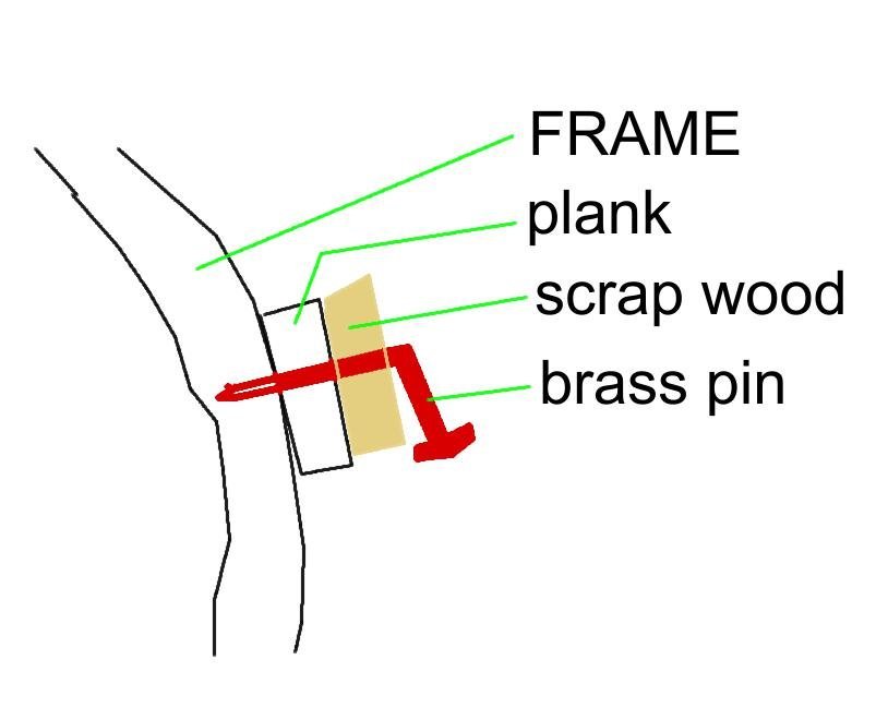
Worse comes to worst, you can use a hitch chock. With PVA, the strength of a bond is directly proportional to the clamping force. Bob's admonition about making sure that dry fit conformation of the plank is correct is important. Factors involved. The diameter of the brass pin should be ~ 1-1.5" in scale. The pre-drilled hole thru the three layers should be snug, Not too snug if you intend to pull the pin. The pin can be nipped and filed if brass trunnels are what you are after. The hole placement is important. There are prescribed rules for this. If the pin is pulled, the hole can be filled with a push fit bamboo trunnel, or wood flour/PVA if a belt and suspenders is not your practice. If both surfaces are pre- coated with PVA and the coats allowed to cure, the plank can then be ironed and the heat will allow the PVA to act like a sort of contact cement.
-
One tool not often listed is a piece of scrap leather and a stick of green or gold or rouge polishing compound. For knives and chisels, frequent stropping intervals can keep a sharp edge, and reduce the need for honing on a "stone".
-
What are these?
Jaager replied to Don Case's topic in Building, Framing, Planking and plating a ships hull and deck
The stern at that level is curved. There is more that one counter timber. This is showing that the one(s) closer to the side also rest on this transom projection. -
What are these?
Jaager replied to Don Case's topic in Building, Framing, Planking and plating a ships hull and deck
The distant inside the frames details are shown at that deck. This leads me to view the two structures in question as projections of the arms of those two transoms. Lower down, what and where those arms are does not affect anything important to any officers. The two objects in question are in officers' country and do affect someone important. -
Sea Witch 1846 by Zooker - RESTORATION
Jaager replied to Zooker's topic in - Build logs for subjects built 1801 - 1850
If you are interested in exploring the bow architecture and bowsprit, there is a paper in NRJ with the title "Which witch is Sea Witch". It seems that the two or three old kits and HIC got it wrong.. The Scientific Sea Witch was my first ship model - the idea was to have something to decorate a fireplace mantel. I had zero knowledge of or experience with tools. I drilled the holes for the masts using a countersink bit in a hand spiral driver. The carved hull was soft enough wood to allow this. -
If you scabbed a thin piece of wood to flush out the steps, it could be sanded down to the 2mm level without compromising the shell. Pine is easy to sand and is not nearly as friable as Basswood. Yellow Poplar would be good for this also. If it to be exposed to water TiteBond III to bond the scabs.
-
You do realize that Hawthorn wood was what August Crabtree used for the carvings on his models? I hope you saved the wood.
-
A for real horror movie. Were I writing the laws for the planet, machines like those would be limited to use on tree farms. If there are any original growth forests or old secondary growth even left, it would be human handled cutting machines and draft horses or oxen and only senile trees would be harvested. The efficiency of these machines is horrifying. They are the equivalent of strip mining the surface of a forest. The one machine missing is a giant chipper shredder for the tops, branches, and parts of the stumps that are not harvested for exotic and specialty grain.
-
From reading the tea leaves about all this: I am betting that we will both be OK using a drill press for wood milling -if the cutters are sharp and the bites are not aggressive. I suspect that lateral resistance from wood is significantly lower than that of metal.
-
Sutherland Welles Ltd. have products that are 3 grades of polymerized Tung oil. They allow for a faster and more predictable gloss level and much less danger of getting a "never dries" finish. There is an old post here where a pure Tung oil application - to a table if I remember it correctly. I suspect that either the product was not as advertised, or too much was applied. In the latter case, a 50% dilution primer coat was skipped and the coat was a too thick 100%. I think it case hardened at the surface and blocked oxygen from getting to the oil where a primer should be and it stayed an oil. It was a sticky mess - especially on a table Floors and tables are probably the one place where the otherwise awful plastic polyurethane finish is the proper choice.
-
spare parts for hull
Jaager replied to Bo Button's topic in Building, Framing, Planking and plating a ships hull and deck
If the plans are adequate, the kit parts can be replicated from stock wood. An early introduction into freedom of scratch building. There may be other parts that can be replaced with scratch built and by starting with better quality wood, have a better looking result. -
Last month, I was browsing Travers Tool for cutters and came across a sale, so I bit: Travers Tool Co. Inc. TTC PRODUCTION 10-200-385 3" .012" Thick 1" Hole Dia. 280 Tooth High Speed Steel Jewelers Saw Item # 10-200-385 Price:$25.55 You Pay:$12.78 EACH Save 50% $12.78 TTC PRODUCTION 10-200-395 3" 1/64" Thick 1" Hole Dia. 230 Tooth High Speed Steel Jewelers Saw Item # 10-200-395 Price:$26.53 You Pay:$13.27 EACH Save 50% $13.27 TTC PRODUCTION 10-200-410 3" .023" Thick 1" Hole Dia. 230 Tooth High Speed Steel Jewelers Saw Item # 10-200-410 Price:$19.23 You Pay:$9.62 EACH Save 50% $9.62 TTC PRODUCTION 10-200-445 3" .051" Thick 1" Hole Dia. 168 Tooth High Speed Steel Jewelers Saw Item # 10-200-445 Price:$26.01 You Pay:$13.01 EACH Save 50% $13.01 I bought a 1" to 1/2" bushing from Jim Byrnes so these blades are ready to go. Fine tooth jewels blades have no set. They are great for cutting a shallow mortise. They are not so good at ripping. The greater the number of teeth per inch on a blade, the less suitable it is as a ripping blade. The gullets fill with wood and the either stop the blade, offer a lot of resistance, and or burn the wood. As long as a 4" tablesaw is able to crank into play a 3" blade, it should be high enough above the table to do the necessary depth of cut. A 4" blade will do it too, but it is overkill. A shallow, interlocking mortise in the grating boards - both NS and EW - if done correctly does not need a jig to get a square finished product. I see two ways to cut the mortises that sort of idiot proof the process. 1) cut the mortises in a block that is the thickness and length of the grating boards and rip that into the final board width. - this loses about 1/2 as kerf. 2) cut the boards to there final size. Temporarily bond them into a block. Cut the mortises in the block and then use the appropriate solvent to release the bond.
-
I buy most of my wood as rough stock. At the lumber yard, the minimum length is 8 feet. Early on, I kept my stock in 4 foot lengths. For processing, I cut those into 16 inch lengths. I found this not to be all that convenient for framing - running out of board too quickly - too many pieces needed and more work for a thickness sander. Now, my sweet spot is 2 feet. Much longer and it would be too long for my bench. The sanded planks also fit in an Aviditi 3" x 3" x 25" mailing box for storage. The shorter boxes are not much less in cost, so there is economy there. In your place, I would rip the log into 10" x 2" x 24" planks.
-
You have provided to geographic location, but if there is access, the poor quality wood can be overlaid with a thin veneer of a species of wood with no pores and a grain that does not clash with the scale of the model. The only tools needed are a quality knife that is sharp and a steel straight edge. Then no filling will be necessary. All that will be needed is a shellac primer (50% strength) and a finish clear coat. The depth and gloss level is controlled by how many coats of shellac are used and if the final coat is dressed with a very fine abrasive- Scotch Brite. A veneer of an Acer sp. should provide a proper deck color and scale appropriate grain, hardness, and closed grain surface. It is much better to use a saw produced veneer. A roller sliced veneer does not lose much to kerf, but the grain pattern is not a natural one. The wood wants to curl if allowed.
-
If I were to work at it, I am pretty sure that I could find more than a few examples of an individual or company making money for providing a quick and easy solution - usually for more money than is deserved - by bundling freely available information or materials. P.T. Barnum's quip about the impossibility of under estimating taste probably rates a laziness corollary. As for the greed of journal publishers, in the dusty corners of my memory, I recall something about journals requiring scientists having to pay a journal to publish a scientific paper and then having an absurd subscription fee for anyone else to read it. The broad circulation and prestige journals are probably free of publication charges, but the competition for acceptance makes them not suitable for the publish or perish game. Fits with the scam of a university confiscating 50% of every grant for services.

